Article

A Refined Dynamic Model for the Planetary Gear Set Considering the Time-Varying Nonlinear Support Stiffness of Ball Bearing

1
School of Mechanical and Electrical Engineering, Zhoukou Normal University, Zhoukou 466001, China
2
State Key Laboratory of Mechanical Transmission, Chongqing University, Chongqing 400044, China
3
College of Mechanical and Vehicle Engineering, Chongqing University, Chongqing 400044, China
4
Ji Hua Laboratory, Foshan 528251, China
*
Author to whom correspondence should be addressed.
Machines 2023, 11(2), 206; https://doi.org/10.3390/machines11020206
Submission received: 9 December 2022 / Revised: 19 January 2023 / Accepted: 23 January 2023 / Published: 1 February 2023
(This article belongs to the Special Issue Safety of Machinery: Design, Monitoring, Manufacturing)

Abstract

:
Dynamics models of planetary gear sets (PGSs) are usually established to predict their dynamic behavior and load-sharing characteristics. The accurate modeling of bearing support stiffness is essential to study their dynamics. However, in most of the existing PGS dynamic models, the effect of characteristics coupling the rolling bearing time-varying nonlinear stiffness with the translational property of PGSs on the dynamic responses was completely neglected. To investigate this problem, a refined dynamic model for PGSs is proposed considering the coupled relationship between the radial translation of the rotating components and the time-varying nonlinear support stiffness of the ball bearing. The refined dynamic model simultaneously considers the coupled effect of the time-varying characteristic caused by the orbital motion of the rolling elements and the nonlinear characteristic caused by Hertzian contact between the rolling elements and raceways of the ball bearing. Comparisons between the simulations and experimental results are presented, which indicate that the PGS vibration spectrums yielded by the proposed time-varying nonlinear stiffness model are much closer to the actual scenarios than those of traditional models. The analysis results provide theoretical guidance for fault monitoring and diagnosis of the rolling bearings used in the PGS.

1. Introduction

Planetary gear sets (PGSs) have the advantages of high-power density, high transmission ratios, large torque-weight ratios, and compactness compared to countershaft gear transmission sets. Thus, they are widely used in many industries such as automotive, aerospace, marine, wind turbines, and machine tools industries [1,2,3]. The rotating members of PGSs are normally supported by rolling element bearings (ball bearing and roller bearing). The support stiffness of the rolling bearings significantly affects the dynamic characteristics, operation reliability, and service life of the PGS [4,5,6,7].
It is well known that the support stiffness of the rolling bearing exhibits a strong time-varying characteristic due to the orbital motion of the finite number of rolling elements and nonlinear characteristics with the support load due to the Hertzian contact between the rolling elements and raceways of the rolling bearings [5,7]. In the past decades, the individual effects of time-varying or nonlinear characteristics of rolling bearings on the fixed-axis gear-rotor-bearing and rotor-bearing systems have attracted intensive attention. Kahraman [8] and Kim [9] studied the effects of bearing deformation on the dynamic performance of the gear-rotor-bearing system. Shi and Li [10] established the interaction between mesh stiffness and dynamic response to allow the real-time variation of mesh stiffness under dynamic conditions and adopted an iterative approach to obtain the dynamic responses. The interactions between the hypoid gear dynamic mesh force and the dynamic mesh stiffness were established for the first time. Liu et al. [11] established a dynamics model of the spur gear pair with the pitch deviation. Meshing characteristics of the spur gear pair with the pitch deviation were studied in order to analyze the time-varying contact ratio and motion characteristics of the system. A refined methodology to simulate the non-linear dynamic response of spur gears was proposed by Cirelli et al. [12,13], which evaluates the nonlinear dynamic effects due to the contact loss by using a multibody model based on contact formulation. Zheng et al. [14] proposed a combined analytical-FEM method to analyze the mesh stiffness and nonlinear dynamics in the centrifugal field, which extended the gear torsional dynamic model to embody the internal dynamic effect in a centrifugal field. Zhu et al. [15] established a piecewise torsional-bending-pendular nonlinear dynamics model to study the nonlinear dynamics response of the face-gear drive system, which can reflect its actual working state as far as possible. In the literature reviewed above, the researchers concentrated on the fixed-axis gear-roller-bearing systems, which have a single-rotor structure. Some transmission systems include the coaxial dual-rotor structure. The main difference between the dual-rotor structure and the single-rotor structure is the introduction of inter-shaft bearings (bearings supporting two rotating members), which couple the outer and inner rotors [16,17]. There are some studies on the dynamic performance of the dual-rotor systems in which the effects of the nonlinearity characteristics of the inter-shaft bearings are taken into account. For example, Hu [18] and Deng [19] established a dual-rotor system dynamic model for an aeroengine spindle. The results showed that the nonlinear support influences the dynamic behaviors of the system significantly. Gupta [20] and Chiang [21] used the transfer matrix method and the finite element method to study the critical speed, mode shape, and unbalanced response of a dual-rotor system. Luo [22] developed a refined inter-shaft bearing model, and the dynamic responses of the dual-rotor system were analyzed. Gao [23], Fukata [24], Tiwari [25,26], Ghafari [27], and Zhang [28] investigated the nonlinear dynamic behaviors of the bearing-rotor system by considering the Hertzian contact and nonlinear stiffness of the inter-shaft bearing when establishing the dynamic model of the bearing-rotor system. In addition, Gao [29] analyzed the bifurcation phenomenon of a dual-rotor system, in which the double frequency excitations of the dual-rotor system and the nonlinearity of the inter-shaft bearing are taken into consideration.
The aforementioned studies regarding the dual-rotor system mainly focus on the fixed-axis bearing-rotor system. The PGS usually includes a coaxial dual-rotor structure. The schematic diagrams of a typical PGS coupled with a dual-rotor structure in the dual-input differential PGS application are shown in Figure 1. Figure 1a illustrates that the system is simultaneously driven by two different elements, including the two input shafts and an output shaft, which is a schematic diagram of the structure only to express the position of the support bearings in the PGS. There are different connection types between the central rotating members of PGS (sun gear, carrier, and ring gear) and input/output ports in practice. In the example shown in Figure 1, the sun gear and the carrier are connected to the input and output ports, respectively. The ring gear is fixed to the housing. The inter-shaft bearings labeled by ② couple the sun gear and carrier, and the bearings labeled by ① couple the rotating components and the housing.
The literature reports intensive studies on the dynamic modeling of a PGS considering bearing factors. Guo and Parker [30,31] proposed a dynamic model of a PGS and investigated the effects of bearing clearance on the system vibrations. Kim [32] analyzed the influence of bearing deformations on the time-varying contact ratios and pressure angles of the sun-planet meshes and ring-planet meshes, as well as the dynamic response of the PGS. Although Wu and Parker [33] and Liu [34] presented the effects of the bearing stiffness of the ring gear on the vibrations of the system, they only established the single-ring gear models. Bahgat [35], Guo [36], and Tatar [37] studied the sensitivity of dynamic characteristics of the PGS, in which the parameters such as the time-varying gear mesh stiffness, bearing support stiffness, and speed have been taken into account. Guo [38] investigated the influence of ring gear support stiffness on the system’s dynamic characteristics by considering the effects of tooth wedging and bearing-raceway contacts. Shao and Liu [39] developed a multi-body dynamic model for a PGS with various values of static bearing support stiffness of the ring gear to reveal the effects of static support stiffness on the system dynamic response. Many experimental and theoretical reports illustrated that in actual systems, the elastic deformation of ring gear can reduce the noise and vibration of the PGS significantly [40]. Additionally, to study the operating condition of rolling bearings, Chen et al. [41] focused on the health state identification of the planetary gearbox and fused the horizontal and the vertical vibration signals, which can extract features from raw data automatically with less dependence on the expert diagnosis experience and the signal processing techniques. Li et al. [42] proposed a novel neural network called the reinforcement learning unit matching recurrent neural network to predict the state trending of rolling bearings.
From the literature survey mentioned above, current studies considering the bearing time-varying or nonlinear characteristics are almost concentrated on fixed-axis bearing-rotor or gear-bearing-rotor systems with inter-shaft bearings. However, for the PGS, the rolling bearings are usually simplified as simple linear spring-damper elements in the dynamic model. The coupling effect of time-varying and nonlinear characteristics of rolling bearing support stiffness (referred to also as the time-varying nonlinear support stiffness in the remainder of this paper as opposed to the conventional static linear stiffness) on the dynamics of the PGS is rarely studied in the literature, which constitutes the major research objective of this work. In this paper, the influence of the time-varying and nonlinear characteristics of rolling bearings on the dynamic characteristics of the PGS is studied. This work is of practical significance for the study of the influence of the time-varying nonlinear support stiffness of rolling bearings on the load-sharing and dynamic characteristics of the PGS. In addition, it can also provide a foundation for the study of dynamic characteristics of the PGS subjected to rolling bearing faults.
The rest of this paper is organized as follows. In Section 2, the refined dynamic model considering the coupled effect of the translational property of the PGS and the time-varying nonlinear support stiffness of rolling ball bearings is proposed. In Section 3, the experiments are carried out to validate the dynamic model proposed in Section 2. Then, in Section 4, comparisons in terms of the dynamic responses of the PGS between the proposed time-varying nonlinear stiffness model and the conventional static linear model are conducted. Finally, conclusions are summarized in Section 5.

2. Dynamics Model of a Planetary Gear Set with Time-Varying Nonlinear Support Stiffness

In view of the influence of the time-varying nonlinear stiffness excitation of rolling bearings on the dynamic characteristics of the PGS, the time-varying stiffness model and nonlinear stiffness model of rolling bearings are proposed in this paper, and coupled into time-varying nonlinear stiffness models to establish the translation torsion coupling dynamic model of a two-stage PGSs parallel compound power-split mechanism (CPSM), as shown in Figure 2. In Figure 2, the solid lines represent the initial situation of the relative position and engagement relationship of PGS components when the inner and outer raceways of the support bearing are not deflected, and the dotted lines represent the influence of the deflection of the inner and outer raceways of the support bearing on the relative position and engagement relationship of PGS components. To simplify the description, s, c, r, and pn represent the sun gear, carrier, ring gear, as well as the nth planet gear, respectively (n = 1, 2,…, N). Each planet gear is supported by the needle bearing on the carrier. ri and rc are the base radii of the gear i (i = s, r, pn) and the distance between the center of the nth planet gear and that of the sun gear. xj and yj represent the translational displacements in the x and y directions and uj (j = s, c, r, pn) describes the torsional displacement in the rotational direction. δi and δo describe the deflection of inner and outer raceways, respectively. Oi and Oo describe the geometric center of inner and outer raceways after deflection, respectively. All the above parameters are the displacement changes of each component relative to the rotating coordinate system fixed on the carrier.
The dynamic model of the PGS with rolling ball bearings is shown in Figure 3. The sun gear and ring gear mesh with the n planet gears through a spring-damping system model have mesh stiffness, kspni, krpni, and damping, csni, crni, respectively. Oj (j = s, c, r, pn) describes the geometric center. kjx, cjx, and kjy, cjy are the support stiffness and damping of each component of the PGS along the x and y axes, respectively. Similarly, kjt and cjt are the support stiffness and damping along the rotational direction of each component.
To investigate the influence of the time-varying nonlinear support stiffness of rolling ball bearings on the dynamic responses of the PGS, the bearing support stiffness of sun, carrier, and ring gears in the x-direction and y-direction (khx and khy, h = s, c, r) are replaced by Khx (t, δhx) and Khy (t, δhy), respectively.
The flexibility of inner and outer raceways is not considered. They are assumed as a rigid body whose translational and torsional degrees of freedom are considered in the proposed dynamic model. In Figure 3, O-U-V is the global fixed coordinate system, whereas oj-xj-yj is the local coordinate system of each component of the PGS. opi-xpi-ypi is fixed at the local coordinate system oc-xc-yc and rotates around the origin of the absolute coordinate O with a constant carrier angular speed Ωc. The translational displacements, xj and yj, and torsional displacements uj are assigned to the sun gear, carrier and ring gear, and the nth planet, respectively. The linear displacement of the angular displacement caused by vibration converted to the circumference is represented by uj, which can be expressed as uj = θjrj, where θj and rj are the angular displacements and the rotating radius of component j, respectively.

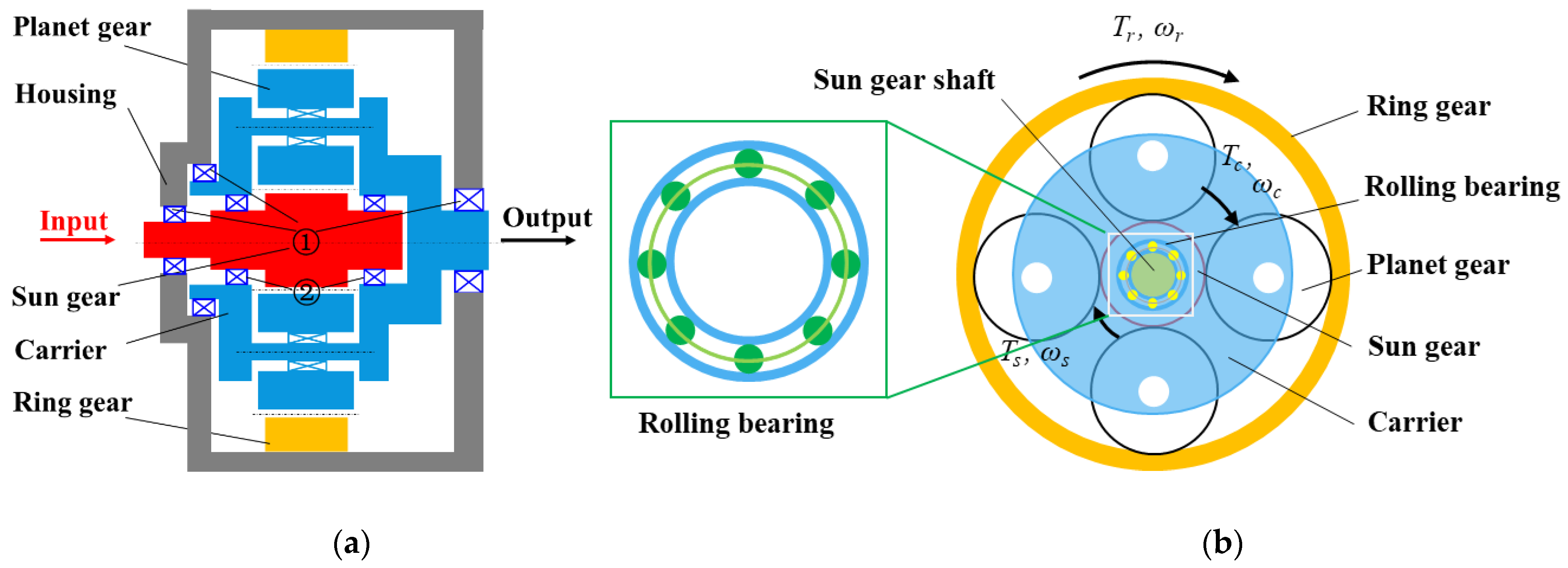
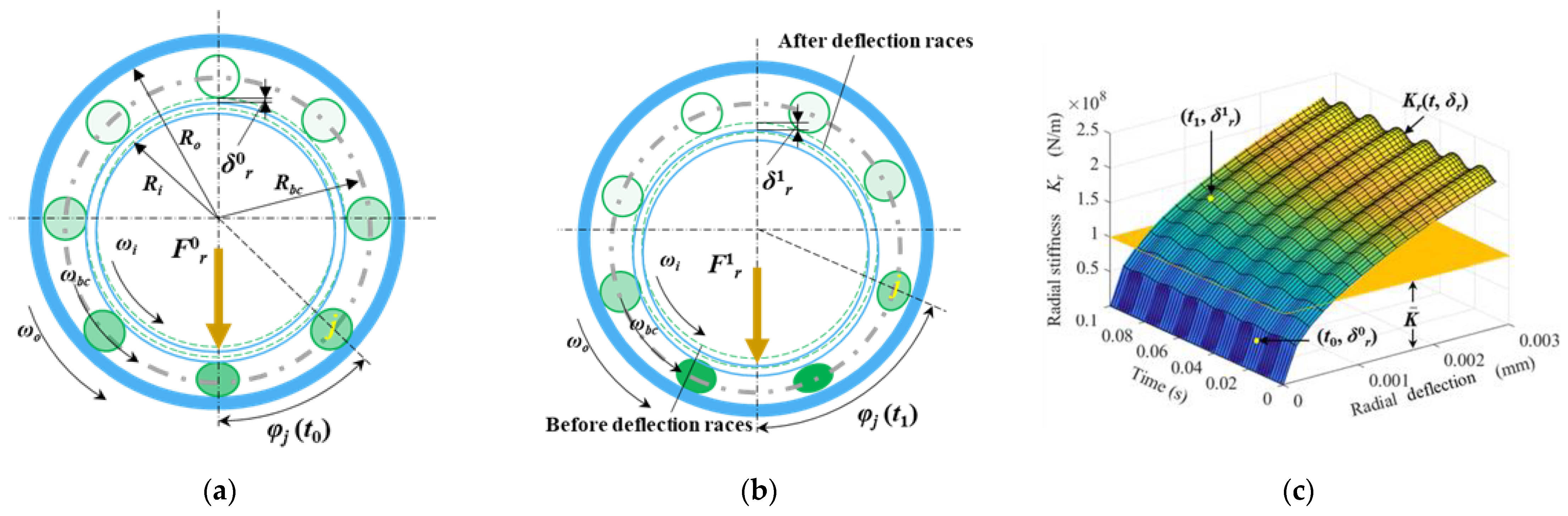
2.1. Actual Support Stiffness and Translation of the Ball Bearing

As presented in Figure 1, a dual-rotor structure of the PGS is presented, which includes an inner-rotor (sun gear) and an outer-rotor (carrier). Without loss of generality, suppose the inter-shaft bearings are the general ball bearings and are located between the inner- and outer-rotors to achieve the coupling of the sun gear shaft and carrier shaft. For the deep groove ball bearing, an appropriate value of preload should be applied to maintain the effective contact between the rolling elements and the raceways, to improve the rolling ball bearing rotation accuracy and support stiffness. In previous work, the rolling ball bearings of the PGS are modeled as linear springs, which means that the bearing support stiffness is usually considered a constant value. However, the rolling ball bearing support stiffness exhibits strong nonlinear and time-varying characteristics, as shown in Figure 4.
Figure 4 shows the schematic diagram of a rolling ball bearing with time-varying loads and rotating speed, and the corresponding position (t, δr) on the time-varying nonlinear support stiffness result. The angular positions and radial deflections of rolling elements of the ball bearing at times t0 and t1 are shown in Figure 4a,b, respectively. The time-varying nonlinear support stiffness result of the rolling ball bearing by considering the coupled effect of the time-varying characteristic caused by the orbital motion of the rolling elements and the nonlinear characteristic caused by Hertzian contact between the rolling elements and raceways of the ball bearing is shown in Figure 4c. For the rolling ball bearings, the inner and outer raceways of the bearing are fixed with different rotating members. The rolling balls are evenly distributed between the inner and outer raceways.
In Figure 4, Ri and Ro represent the contact radii of the inner and outer raceways, respectively. Rb is the radius of the rolling ball. Riw and Row are the groove bottom radii of the inner and outer raceways, respectively. riw and row are the radii of the inner and outer raceway curvatures, respectively. Rbc is the radius of the pitch circle, and Rbc = (Ri + Ro)/2. φj(t) is the rotational angle of the jth rolling ball with respect to the x-axis at the time moment t, which can be expressed as
φ j ( t ) = ω b c t + 2 π ( j 1 ) N
{ ω b c = ω i 2 ( 1 R b R b c ) , ω o = 0 ; ω b c = ω o 2 ( 1 + R b R b c ) , ω i = 0 ; ω b c = ω i R i + ω o R o R i + R o .
where N is the number of rolling balls. ωbc, ωi, and ωo represent the rotating speeds of the cage, inner raceway, and outer raceway, respectively. The rotating frequency of the cage fbc equals ωbc/60, and the ball passage frequency fp equals Nfbc.
In addition, in Figure 4, δ0r and δ1r are the radial deformations caused by the varying normal contact F0r and F1r at times t0 and t1, respectively. When the rolling ball bearing is operating under a given radial load and speed condition, the inner and outer raceways of the rolling ball bearing will be deflected, and the position relationship is given in Figure 5a. O is the initial center position of the inner and outer raceways. Oi and Oo are the center positions of the inner and outer raceways after being deflected, respectively. δi and δo are the contact deformations of the inner raceway-ball and outer raceway-ball, respectively. rL is the bearing radial clearance.
As shown in Figure 5b, the rolling balls and the inner/outer raceway are important elements in modeling the nonlinear support stiffness of rolling ball bearings. According to the Hertzian contact theory, the contact pattern between a ball and a raceway (inner or outer) of the deep groove ball bearing under load is elliptical rather than the theoretical point contact, as shown in Figure 5. Ob is the ball center. A localized u-v-w coordinate system is established whose directions are along the rolling direction, the axial direction, and the contact normal direction, respectively. The radii of curvature of the rolling ball in the uw and vw plane are Rbx and Rby, respectively. The semi-major axis b and semi-minor axis a of the elliptical contact area between the rolling ball and the raceway are calculated by Hertzian contact theory.
The load–deformation relationship between the jth rolling ball and the raceways is:
F θ j = K n δ j n
where Fjθ and δjθ are the normal contact force and normal contact deformation between the jth rolling ball and the raceways, respectively; Kn is the effective contact stiffness constant for the inner raceway-rolling ball-outer raceway contacts and is a function of the bearing geometry and material properties [43]. It can be expressed as Equation (4). It should be noted the exponent n is 3/2 and 10/9 for the point contact (ball bearings) and line contact (roller bearings), respectively.
K n = 1 [ ( 1 / K i ) 1 / n + ( 1 / K o ) 1 / n ]
The load–deformation coefficients of inner and outer raceways Ki and Ko can be expressed as Equation (5) [44], respectively.
{ K i = 2 . 15 × 10 5 ( ρ i ) 1 / 2 ( δ i ) 2 / 3 K o = 2 . 15 × 10 5 ( ρ o ) 1 / 2 ( δ o ) 2 / 3
The normal deformations δi and δo between the rolling ball and the inner/outer raceways are, respectively, the functions of the difference in curvatures between the rolling ball and the raceways, F(ρi) and F(ρo). The expressions of F(ρi) and F(ρo) are as follows, respectively:
{ F ( ρ i ) = | 1 / R i x 1 / R i y | + | 1 / R b x 1 / R b y | ρ i F ( ρ o ) = | 1 / R b x 1 / R b y | + | 1 / R o x 1 / R o y | ρ o
where the sum of flexion radii between the rolling ball and inner/outer raceways are written as Equation (7).
{ ρ i = ( 1 R i x + 1 R i y ) + ( 1 R b x + 1 R b y ) ρ o = ( 1 R b x + 1 R b y ) + ( 1 R o x + 1 R o y )
where Rbx = Rby = Rb, Rix = Riw, Rby = −riw, Rox = −Row, Roy = −row, as shown in Figure 5. In addition, the minus sign ‘−’ means that the curved surface is concave. Otherwise, the surface is convex.
According to the geometric relationship in Figure 6, the effective radial contact deformation of the jth ball is
δ j r = ( δ i x δ o x ) cos φ j + ( δ i y δ o y ) sin φ j r L / 2
{ δ i r = ( δ i x ) 2 + ( δ i y ) 2 δ o r = ( δ o x ) 2 + ( δ o y ) 2 δ r = ( δ i x δ o x ) 2 + ( δ i y δ o y ) 2
where δix and δiy are the deformation components of the inner raceway center in the horizontal and vertical directions, respectively. δox and δoy are the deformation components of the outer raceway center in the horizontal and vertical directions, respectively. If δjr is less than zero, it means that the jth ball is not in contact with the raceways.
Figure 6 illustrates the geometric relationship of groove curvature centers (corresponding to the jth ball) of the inner and outer raceways before and after deflection. Figure 6 shows a generic geometry (3D) of the angular rolling bearings considering the radial and axial displacement (z direction) of the raceways. In the studied PGS system, the gears are spur gears and the rolling bearings are deep-groove ball bearings as the axial reaction forces and displacements are negligible compared to the radial reaction forces and displacements. The non-constant contact angle αj of the rolling ball is the angle between the curvature center lines of raceways before deflection and after deflection. A0 and Aj are the relative distances of groove curvature centers before and after deflection, and are expressed by Equations (10) and (11), respectively. δijz and δojz are the deformation components of the groove curvature centers along the z-axis for the inner and outer raceways, respectively. Similarly, δijr and δojr are the deformation components along the radial direction (r-axis), respectively.
A 0 = ( R i w + r i w ) ( R o w + r o w )
A j = ( δ j z ) 2 + ( δ j r ) 2
where δjr and δjz are the deformation components of the jth rolling ball along with the radial r (x- or y-axis) and axial z-axis, respectively.
The time-varying position distribution of rolling elements of rolling bearings is comprehensively considered (Figure 4a). The overall radial deformations of the bearing under different loads (Figure 4b and Figure 6) are considered to establish the deflection model of the inner and outer rings of rolling bearings. As a two-dimensional translational-torsional dynamic model of the PGS is investigated in this paper, the force and displacement in the z-direction are not considered. Thus, the expressions of time-varying nonlinear support stiffness for the rolling ball bearing are as follows:
K x ( t ,   δ r ) = K n j N ( A j A 0 ) n cos 2 ( φ j ( t ) ) ( A j ) 3 ( n A j ( δ j r ) 2 A j A 0 + ( A j ) 2 ( δ j r ) 2 ) K y ( t ,   δ r ) = K n j N ( A j A 0 ) n sin 2 ( φ j ( t ) ) ( A j ) 3 ( n A j ( δ j r ) 2 A j A 0 + ( A j ) 2 ( δ j r ) 2 )

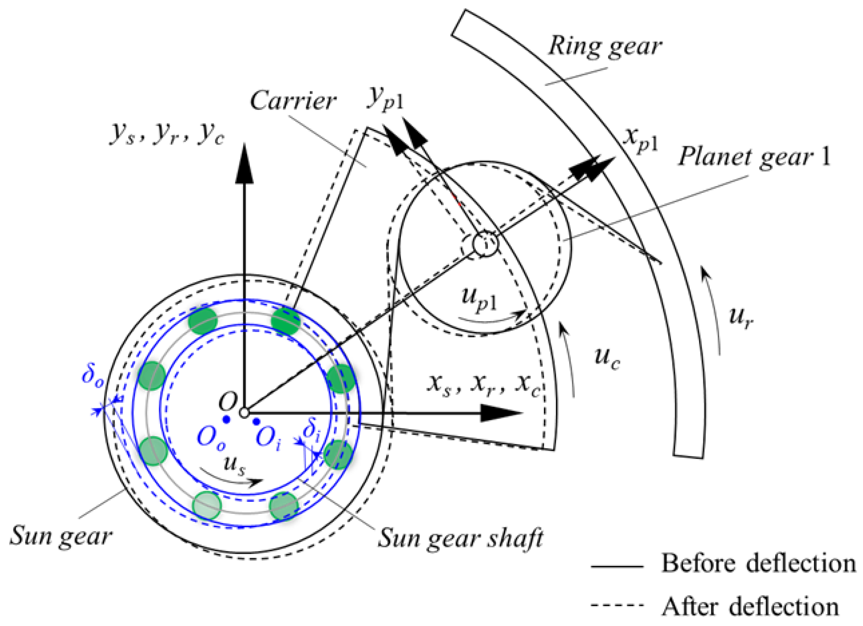
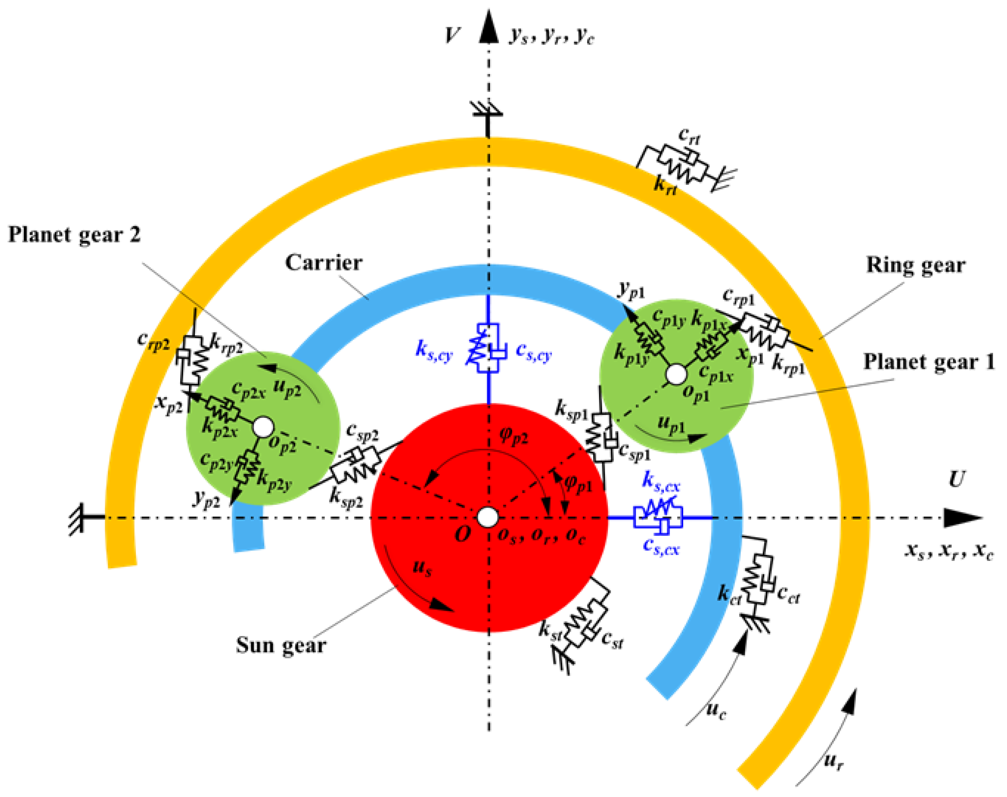
2.2. Lumped Parameter Model of a PGS Coupled with the Time-Varying Nonlinear Support Stiffness

According to the principle of force and torque balance, the motion equations of the PGS can be derived as follows:
The motion equations for the carrier are:
m c ( x ¨ c 2 Ω c y ˙ c Ω c 2 x c ) + i = 1 n k p i x δ c p n x + i = 1 n c p i x δ ˙ c p n x + K c x ( θ ( t ) , δ c x ) x c + c c x x ˙ c = 0 m c ( y ¨ c 2 Ω c x ˙ c Ω c 2 y c ) + i = 1 n k p i y δ c p n y + i = 1 n c p i y δ ˙ c p n y + K ( θ b c ( t ) , δ c , s y ) y c + c c y y ˙ c = 0 ( I c / ( r c ) 2 ) u ¨ c + i = 1 n k p i t δ c p n u + i = 1 n c p i t δ ˙ c p n u + k c t u c + c c t u ˙ c = T c / r c
The motion equations for the sun gear are:
m s ( x ¨ s 2 Ω c y ˙ s Ω c 2 x s ) i = 1 n k s p i δ s p i sin φ s p i i = 1 n c s p i δ ˙ s p i sin φ s p i + K ( θ b c ( t ) , δ c , s x ) x s + c s x x ˙ s = 0 m s ( y ¨ s + 2 Ω c x ˙ s Ω c 2 y s ) + i = 1 n k s p i δ s p i cos φ s p i + i = 1 n c s p i δ ˙ s p i cos φ s p i + K ( θ b c ( t ) , δ c , s y ) y s + c s y y ˙ s = 0 ( I s / ( r s ) 2 ) u ¨ s + i = 1 n k s p i δ s p i + i = 1 n c s p i δ ˙ s p i + k s t u s + c s t u ˙ s = T s / r s
The motion equations for the ring gear are:
m r ( x ¨ r 2 Ω c y ˙ r Ω c 2 x r ) i = 1 n k r p i δ r p i sin φ r p i i = 1 n c r p i δ ˙ r p i sin φ r p i + K ¯ r x x r + c r x x ˙ r = 0 m r ( y ¨ r 2 Ω c x ˙ r Ω c 2 y r ) + i = 1 n k r p i δ r p i cos φ r p i + i = 1 n c r p i δ ˙ r p i cos φ r p i + K ¯ r y y r + c r y y ˙ r = 0 ( I r / ( r r ) 2 ) u ¨ r + i = 1 n k r p i δ r p i + i = 1 n c r p i δ ˙ r p i + k r t u r + c r t u ˙ r = T r / r r
The motion equations for the nth planet gear are:
m p i ( x ¨ p i 2 Ω c y ˙ p i Ω c 2 x p i ) + i = 1 n k s p i δ s p i sin φ s p i + i = 1 n c s p i δ ˙ s p i sin φ s p i + i = 1 n k r p i δ r p i sin φ r p i + i = 1 n c r p i δ ˙ r p i sin φ r p i k p i x δ c n x c p i x δ ˙ c n x = 0 m p i ( y ¨ p i 2 Ω c x ˙ p i Ω c 2 y p i ) i = 1 n k s p i δ s p i cos φ s p i i = 1 n c s p i δ ˙ s p i cos φ s p i i = 1 n k r p i δ r p i cos φ r p i i = 1 n c r p i δ ˙ r p i cos φ r p i k p i y δ c n y c p i y δ ˙ c n y = 0 ( I p i / ( r p i ) 2 ) u ¨ p i + i = 1 n k s p i δ s p i + i = 1 n c s p i δ ˙ s p i i = 1 n k r p i δ r p i i = 1 n c r p i δ ˙ r p i = 0
In these equations, the relative angle φspn (φrpn) and deformation δspn (δrpn) between the sun (ring) gear and the nth planet gear are determined in Figure 7. Tμ (μ= s, c, r), mj, and Ij denote the torque, mass, and moment of inertia of each component of the PGS, respectively.
Figure 6 shows the gear mesh states of the PGS. The mesh angles of the gear pairs for the sun-planet and planet-ring are as follows:
φ s p n = α s φ p n φ r p n = α r + φ p n
where αs and αr are the transverse pressure angles of the sun-planet and the planet-ring gear meshes, respectively. φpn is the position angle of the nth planet gear.
The mesh deformations between the nth planet gear and the sun/ring gear are usually defined as the dynamic transmission error, which can be expressed as Equation (20). Similarly, the deformations between the nth planet gear and carrier are written as Equation (21).
δ s p n = ( x p n x s ) sin φ s p n + ( y s y p n ) cos φ s p n + u s + u p n δ p n r = ( x r x p n ) sin φ r p n + ( y p n y r ) cos φ r p n + u r u p n
δ c p n x = x c x p n u c sin φ p n δ c p n y = y c y p n + u c cos φ p n δ c p n u = ( x p n x c ) sin φ p n + ( y c y p n ) cos φ p n + u c
In addition, fm and tm denote the mesh frequency and mesh period of the PGS, which can be expressed as follows:
f m = ( ω s ω c ) Z s
where Zr and Zs are teeth numbers of the ring gear and sun gear, respectively; ωs and ωc represent the absolute rotating speed of the sun gear and the carrier, respectively.
After integrating the dynamic differential equations of each component, the matrix form of the equations above can be expressed as
M q ¨ + Ω c G q   ˙ + ( K b ( t ,   δ ) + K m ( t ) + Ω c K Ω )   q = T + F ( t )  
where q is the displacement vectors, M is the system mass matrix, and Ωc represents the angular speed of the carrier. G is the gyroscopic matrix. Kb(t, δ) represents the matrix of support bearing stiffness. Km(t) represents the gear mesh stiffness matrix, and KΩ the centripetal stiffness matrix. T and F are the static torque and the static load vector, respectively. The displacement vector q can be written as
q = { x c , y c , u c , x s , y s , u s , x r , y r , u r , x p 1 , y p 1 , u p 1 , , x p n , y p n , u p n } T

2.3. The Solving Algorithm of the Refined Dynamics Model

Considering that the vibration characteristics of the PGS are affected by the time-varying nonlinear support stiffness of the ball bearings, the flowchart of step-by-step time integration to obtain the dynamic response of the system is shown in Figure 8. The dynamic responses of the system model can be obtained by utilizing the fourth-order Runge-Kutta numerical integration method to solve the differential equation sets. However, as the time-varying nonlinear support stiffness Khx(t, δhx) and Khy(t, δhy) are dependent on time t and the raceways deflections δhx and δhy, the dynamic responses of bearing raceways in the last time step must be obtained to obtain the bearing support stiffness in the current time step. The solving algorithm is demonstrated in Figure 8. For traditional solving algorithms, the integration interval for the dynamic differential equations of the system runs through the entire solution process as shown in the left dotted line area in Figure 8, in which the initial values of the support stiffness are defined as constants, i.e K ¯ = 108 N/m. Compared to the traditional method, the proposed method inserts the inner loop in the Runge-Kutta algorithm to establish the dynamic couple relationship between the translations of the PGS and the time-varying nonlinear support stiffness of the ball bearing. As the time-varying property of time-varying nonlinear support stiffness, i.e., Khx(t, δhx) and Khy(t, δhy), is considered in the current dynamic model, an iteration is introduced as an inner cycle, as shown in the right dotted line area in Figure 8. At the beginning of the inner cycle at the tn+1 moment, the support stiffness of the ball bearing in the x and y axes is calculated via the displacements of the PGS components at the previous tn moment. The iteration continues until convergence in this time step.

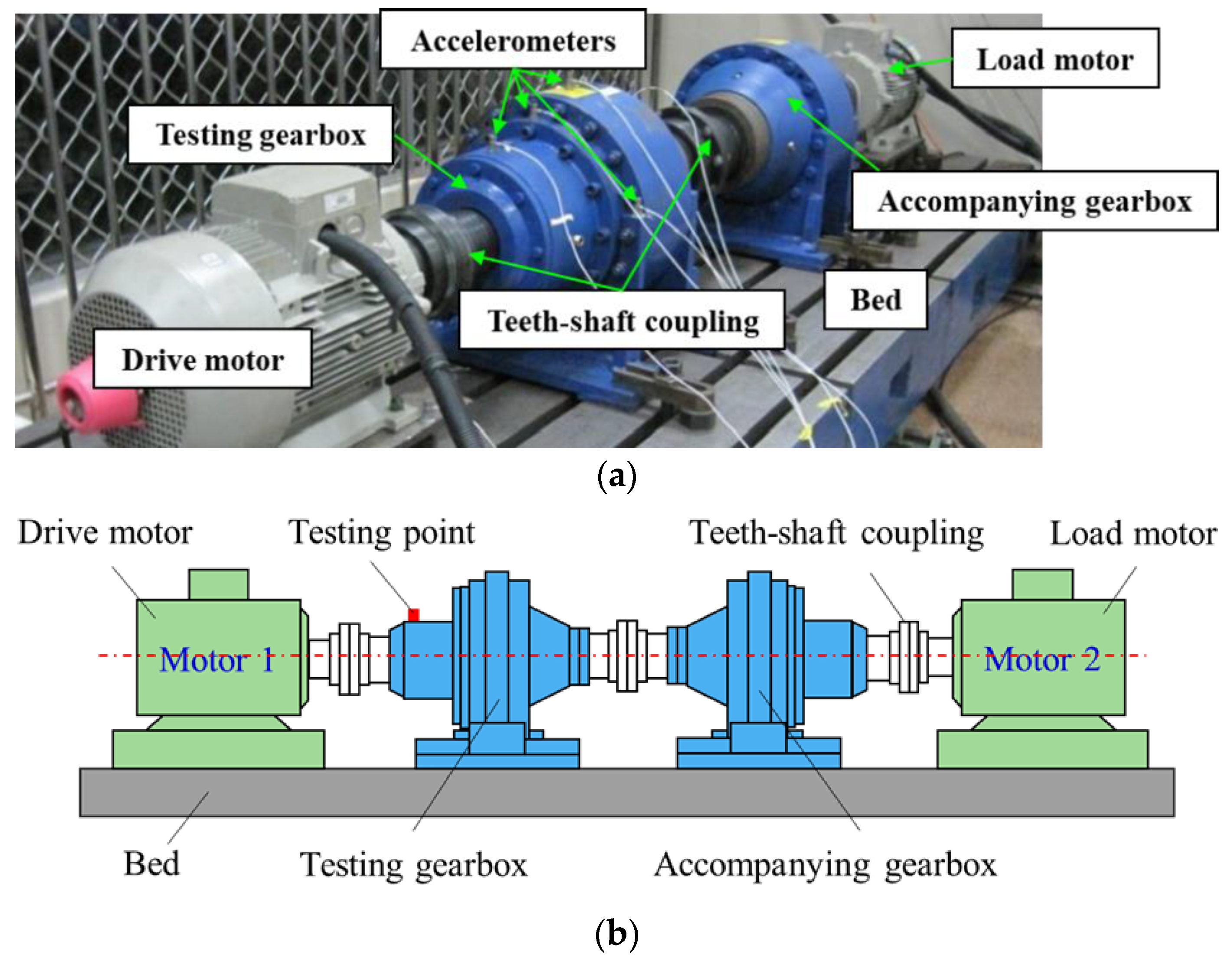
3. Experiment and Comparisons

The vibration signals picked up on the planetary gearbox housing include vibration signals from shafts, bearings, brackets, motors, and other components and background noise signals, which make the vibration signal components collected by the acceleration sensor very rich. As the planet gear in the PGS system not only rotates around its own axis, but also orbits around the central axis of the sun gear, the vibration transmission paths from the planet-ring position or planet-sun mesh position to the signal pickup position show strong periodic variation, resulting in a complex modulation phenomenon in the vibration signals. The pass frequency of the rolling elements is the orbital motion of the rolling elements and the nonlinear characteristic caused by Hertzian contact between the rolling elements and raceways of the ball bearing hidden in the vibration signal of the bearing housing of the shafts, which need to be obtained by performing the time-synchronous average signal (TSAS) to demodulate the test vibration signal. In order to validate the simulation model in Section 2, a planetary gearbox (PGB) test rig is employed, as shown in Figure 9, to collect the vibration acceleration signals of the PGS.
Figure 9a shows the experimental apparatus, which consists of two motors, two PGBs, a computer, and a set of vibration acquisition instruments. The testbed is arranged symmetrically, i.e., PGB #1 and PGB #2 have the same structure, and the same with the two motors. The two motors are SIEMENS three-phase induction motors. The rated power is 15 kW and the rated speed is 1450 rpm. Motor #1 is used for driving and motor #2 is for loading. To measure the vibration acceleration signals, a Kistler integrated circuit piezoelectric accelerometer is installed on the housing of the input bearing of PGB #1 near the sun gear, as shown in Figure 9b. The vibration signal acquisition system is NI 9181, and the sampling frequency is set to 20,480 Hz. The acquisition time is 10 s. The motor and the planetary gearbox, and the test gearbox and the accompanying gearbox are connected by torque couplings. The teeth-shaft couplings are used to connect these components. The design parameters of the PGB are described in Table 1.
Figure 10 shows the diagram and physical photo of the PGS in the gearbox, which includes the ring gear, carrier, sun gear (input shaft), and planet gears. For the planetary gearbox, the input component is the sun gear, and the fixed component is the ring gear. Thus, the relationship between rotating speeds of different members is written as follow:
ω c = ω s + R ω r 1 + R
where R = Zr/Zs, and Zr and Zs are the tooth number of the ring gear and sun gear, respectively.
A series of tests with fixed input speeds of 300 rpm, 500 rpm, 700 rpm, and 900 rpm are carried out under a load of 200 N⋅m. To obtain the dynamic response of the test point, the acceleration signals in the y-direction are measured. Figure 11 shows the root-mean-square (RMS) values of the measured results and the simulated results versus the input speed under different support stiffness cases, as described in Table 2.
In the static linear case, four stiffness values are used to describe the bearing support stiffness of the sun and carrier. In the time-varying nonlinear case, the bearing support stiffness of the sun and carrier are time-varying and dependent on the instantaneous displacements of bearing raceways.
From Figure 11, it can be found that the time-varying nonlinear case and static linear case with K ¯ = 2 × 10⁸ N/m are close to the measured results. The boxplots between the simulation and experimental results are shown in Figure 11b. It can be seen that the responses of the time-varying nonlinear case are closer to the experimental results.
The results of the condition with the input speed of 700 rpm are illustrated in Figure 12. Figure 12a shows the measured vibration signal and its TSAS. Figure 12b shows the TSAS of the measured results and the simulation results of the time-varying nonlinear case and the static linear case with K ¯ = 1 × 10⁸ N/m. It can be observed there are obvious differences between the experimental results and simulation results, and the results of the time-varying nonlinear case are closer to that of the experimental results.
Figure 13 shows the results of Figure 12b in the logarithm frequency domain. Herein, fm denotes the mesh frequency of the PGS. In Figure 13, the frequency spectrum of the measured signals is plotted by the solid line, and the frequency spectrums with or without time-varying nonlinear support stiffness are plotted by the dashed line and dotted line, respectively. The simulation results have fewer spectral lines, which may be caused by the existence of small eccentricity errors of planet gears and ring gears, and other manufacturing errors.
Figure 13a shows the structure of the acceleration logarithm frequency spectrum over a wider range, 0–750 Hz, while Figure 13b is the zoomed-in spectrum in 0–200 Hz for a clearer presentation. In Figure 13, it can be found that the frequency spectrum of the time-varying nonlinear case includes numerous sidebands, which is closer to the experiment. Additionally, it is obvious that the frequency component of the PGS is monotonous, as shown in Figure 13a. Although there are lots of frequency components in this frequency spectrum, the mesh frequency fm is 156 Hz, and its harmonics can be observed clearly. For the time-varying nonlinear case, the sidebands possess obvious peaks in addition to the fm and its harmonics when compared to those of the static linear case. In Figure 13b, the time-varying nonlinear case is denoted by the dashed line with the ‘+’ markers. The detailed sideband components are illustrated with red symbols above each term, which are symmetrically distributed on both sides of the mesh frequency fm. The sidebands in the left side of the mesh frequency are 3fbc+fo, fp-fi, fbpfi-fbc, fp+fbpfo, fm-fbpfo+fbc, fm-fp+fbc, and fm-3fbc-fo, where fi and fo denote the rotating frequency of inner and outer raceways, respectively; fbc, fbpfi, and fbpfo denote the frequency of time-varying support stiffness and the passing frequency of the ball to inner and outer raceways, respectively.
Compared to those of the static linear cases, the sidebands of the time-varying nonlinear case include the ball passing frequencies, fbc, fp, fbpfi, and fbpfo, which are much closer to the real scenario. Thus, the proposed model considering the time-varying nonlinear support stiffness provides the possibility of bearing fault feature extraction and is beneficial for the fault diagnosis of PGSs’ bearings.

4. Dynamic Simulation and Discussion

A spur PGS coupled with a dual-rotor system including four equally spaced planet gears is taken as the research object in this section, as shown in Figure 1. The detailed parameters are described in Table 1. Though the static linear bearing support stiffness is widely used to simulate the dynamic characteristics of the PGS, the time-varying nonlinear support stiffness model of the rolling ball bearing can more accurately reflect the dynamic response characteristics of the PGS system. The dynamic responses (in terms of the vibration, load-sharing factor, and center trajectory) of the time-varying nonlinear support stiffness are directly compared to those of the static linear cases, as described in Table 2 via a speed-sweep analysis.

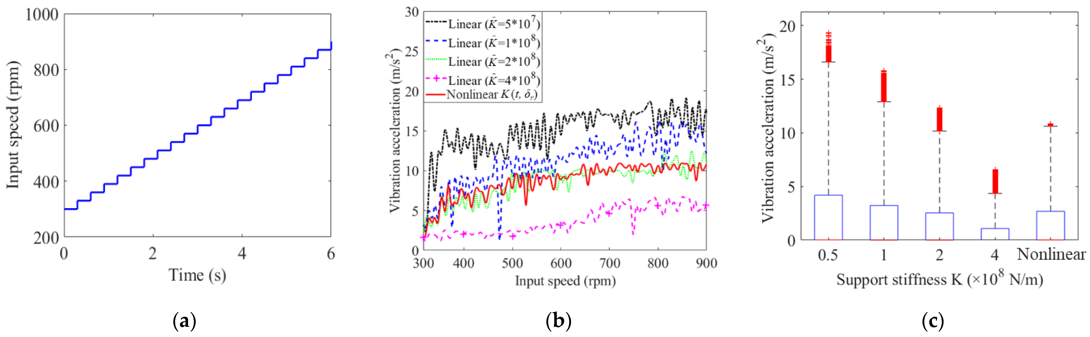
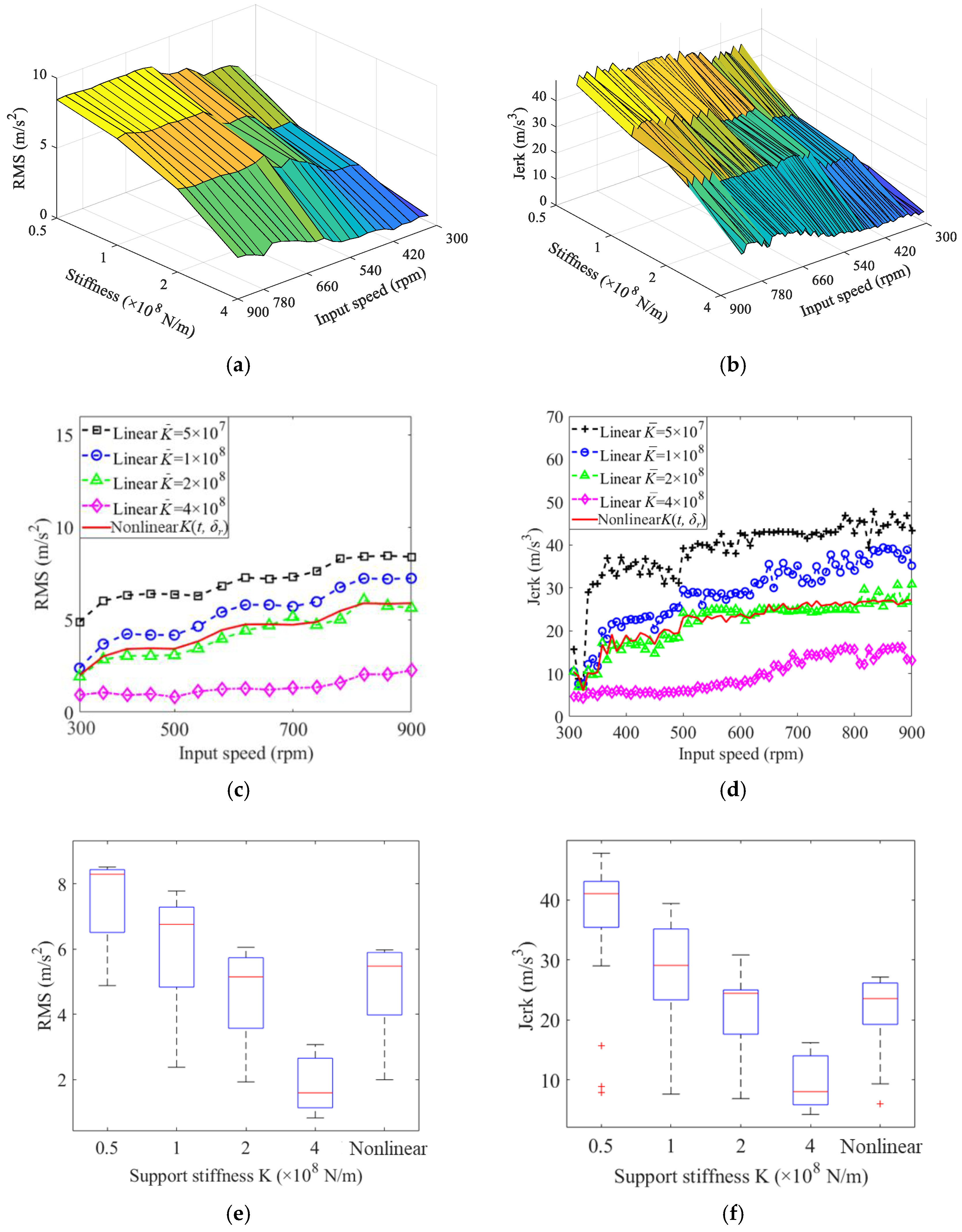
4.1. Influence of Support Stiffness and Input Speed on the Vibrations

To investigate the dynamic responses under different static linear bearing support stiffness conditions and input rotating speeds, four static values of K ¯ are considered to provide comparisons with that of the proposed time-varying nonlinear support stiffness.
In the speed-sweep condition, an increasing speed-sweep (from 300 rpm to 900 rpm with an interval of 30 rpm in 6 s, as shown in Figure 14a) simulation is conducted. The load is 200 N/m.
For the speed-sweep simulation, the time-history vibration responses of the sun gear and carrier for different static linear bearing support stiffness cases and the proposed time-varying nonlinear support stiffness and their boxplots are shown in Figure 14b,c, respectively, which can reflect the stability of the corresponding vibration responses for increasing the speed-sweep process.
In Figure 14b, the vibration amplitudes increase with the input speed and decrease with the static value of support stiffness, and the results of the time-varying nonlinear support stiffness are very close to those of the static linear case K ¯ = 2 × 10⁸ N/m. In Figure 14c, for the linear support stiffness cases, the number and amplitude of outliers decrease with the static value of support stiffness, and the variance of vibration response indicates that the stability of nonlinear support stiffness is better than that of the static linear case with K ¯ = 2 × 10⁸ N/m.
The root-mean-square (RMS) and jerk (peak to peak of RMS) values for different support stiffness cases at various input speeds are calculated, and the corresponding 3D view, front view, and boxplot are illustrated in Figure 15. From Figure 15, similar conclusions as those of Figure 14 are obtained. The vibration responses for the time-varying nonlinear case are weaker than those of static linear cases with K ¯ = 0.5 × 10⁸ N/m and K ¯ = 1 × 10⁸ N/m, but stronger than that of the static linear case with K ¯ = 4 × 10⁸ N/m. In addition, the dynamic responses of the time-varying nonlinear case are close to that of the linear case with K ¯ = 2 × 10⁸ N/m. However, in Figure 15, the variance of the vibration response of the static linear case with K ¯ = 1 × 10⁸ N/m is largest, and the results of the static linear case with K ¯ = 4 × 10⁸ N/m are smallest. Meanwhile, the stability of the results for the time-varying nonlinear case is better than that of the static linear case with K ¯ = 2 × 10⁸ N/m.

4.2. Influence of Support Stiffness and Input Speed on the Load-Sharing Factor

The load-sharing factors (LSFs) of the PGS with respect to different bearing support stiffness conditions and input speeds are shown in Figure 16. It can be found that the LSFs increase with the input speed but decrease with the bearing support stiffness. The fluctuations in LSFs for K ¯ = 0.5 × 10⁸ N/m and K ¯ = 2 × 10⁸ N/m are largest and the peak occurs at 600 rpm; the peak of K ¯ = 1 × 10⁸ N/m occurs at 800 rpm, as shown in Figure 16b. The LSFs for the static linear case with K ¯ = 4 × 10⁸ N/m and the time-varying nonlinear case are stabler than others and there are no outliers and obvious peaks, as shown in Figure 16b,c.

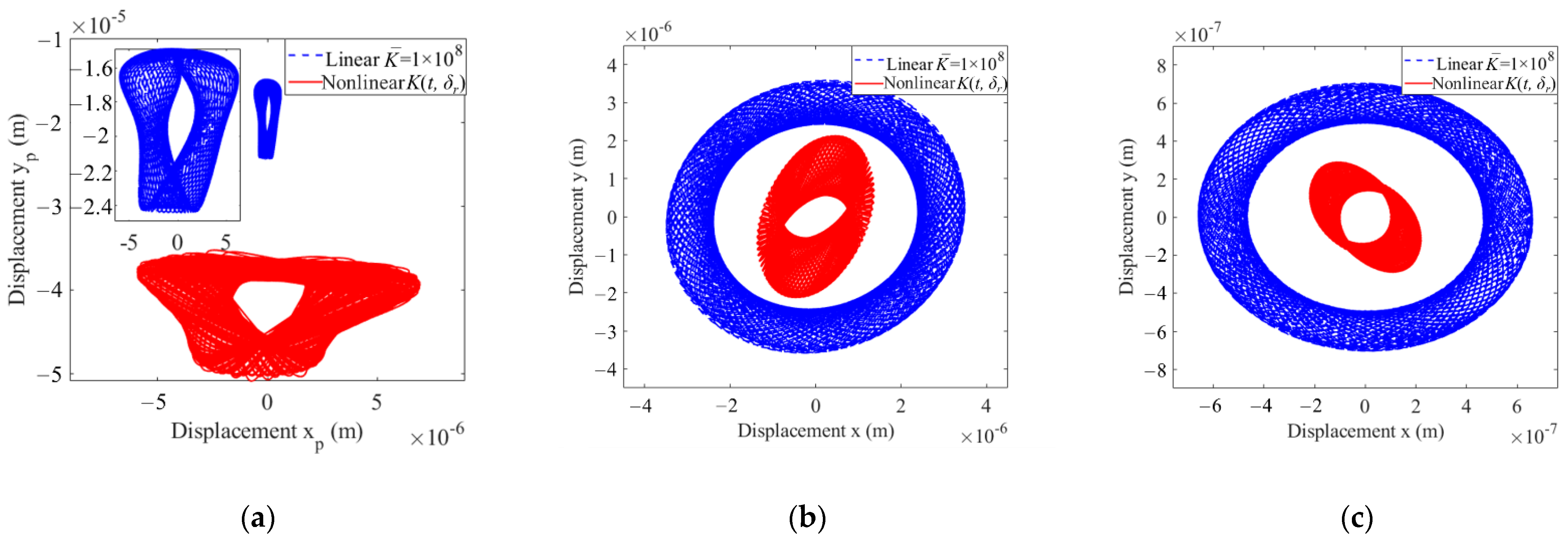
4.3. Influence of Support Stiffness and Input Speed on the Center Trajectories

The center trajectory comparison of the planet gear, sun gear, and carrier with an input speed of 700 rpm is shown in Figure 17. Trajectories with or without considering the time-varying nonlinear support stiffness of the rolling ball bearings are plotted by dotted lines and solid lines, respectively. It can be seen that the effect of the time-varying nonlinear support stiffness makes the trajectory curves of the planet gear increase and decrease significantly in x and y directions, respectively, and the rotational center position of the planet gear deviates significantly, as shown in Figure 17a. The time-varying nonlinear support stiffness significantly reduces the amplitude of trajectory curves of the central components, due to the corresponding translational movement being affected by the time-varying nonlinear support stiffness characteristics of the ball bearing. However, their rotational center positions are unchanged, as shown in Figure 17b,c, respectively.

5. Conclusions

In this paper, a refined dynamic model of a planetary gear set (PGS) is proposed by coupling their translational property with the time-varying nonlinear support stiffness of the rolling bearings. In this model, the time-varying nonlinear support stiffness model simultaneously considers the time-varying and nonlinear characteristics of the bearing support stiffness, which are caused by the nonlinear Hertzian contact restoring force and parametrically excited periodic variation of the contact stiffness. To obtain the dynamic responses from the proposed dynamic model, an improved time integration algorithm is presented by introducing an inner iteration cycle to calculate the time-varying nonlinear support stiffness based on the instantaneous displacements of bearing raceways. The simulation responses of the proposed model considering the time-varying nonlinear bearing support stiffness is directly compared to the experimental results, which demonstrate the advantages of the proposed model as opposed to previous models considering the static linear bearing support stiffness. The influences of the time-varying nonlinear support stiffness on the time- and frequency-domain dynamic responses of the PGS are analyzed. Some conclusions are drawn as follows:
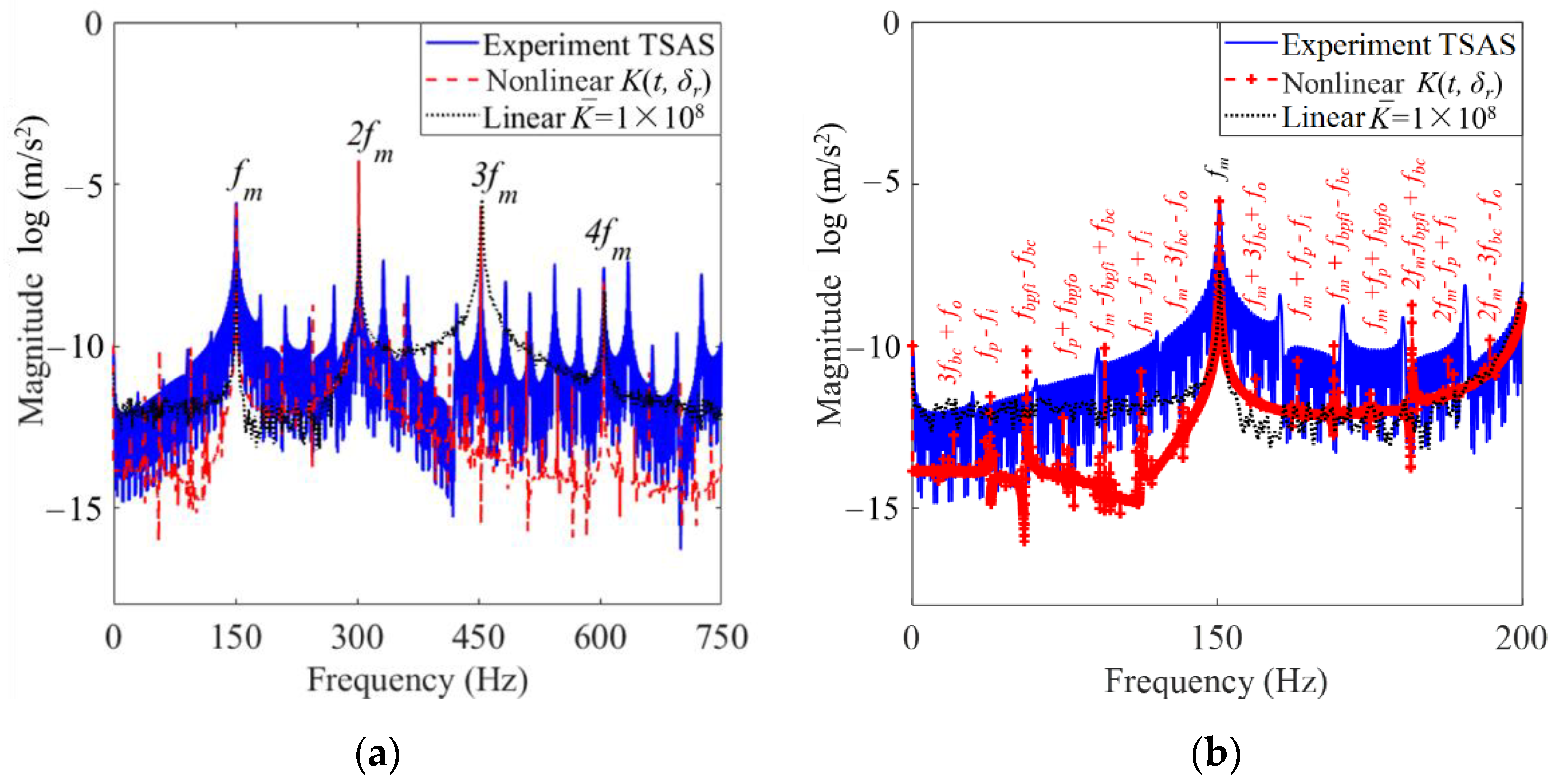
  • Compared to the static linear bearing support stiffness conditions, the sidebands of the time-varying nonlinear support stiffness condition in the logarithm frequency spectrum possess additional ball passing frequencies (fbc, fp, fbpfi, and fbpfo), which are much closer to the real scenario.
  • The conventional static linear bearing support stiffness models, which usually assume an empirical constant value, cannot faithfully reflect the dynamic scenario of the system. The proposed refined support stiffness model is close to the actual situation, which may provide theoretical guidance for the condition monitoring and fault diagnosis of PGSs’ bearings.
  • The vibration amplitudes of the sun gear and the center trajectories of the sun gear, carrier, and planet gear are greatly affected by the time-varying nonlinear support stiffness of bearings.
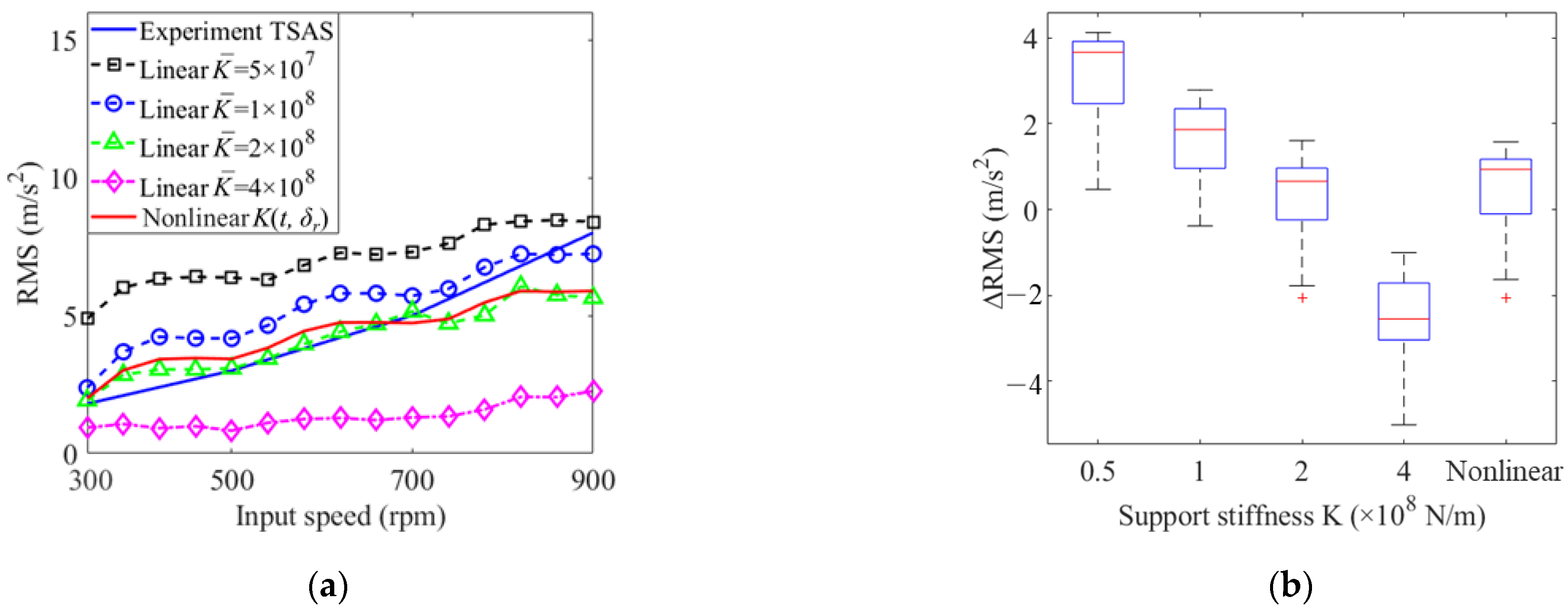
  • The vibration responses of the time-varying nonlinear case and the static linear case with K ¯ = 2 × 10⁸ N/m are very close to that of the experiment. However, the dynamic responses of the time-varying nonlinear case are stabler.

Author Contributions

Conceptualization, X.Y.; validation, X.Y. and C.Z; formal analysis, X.Y. and C.N.; data curation, Z.X.; writing—original draft preparation, X.Y. and C.Z.; writing—review and editing, X.Y. and W.Y.; supervision, W.Y. and W.H. All authors have read and agreed to the published version of the manuscript.

Funding

This research was funded by the National Key R&D Program of China (2021YFB2011400), the National Natural Science Foundation of China (Grant Nos. 52105086; 52035002), and the China Postdoctoral Science Foundation (Grant No. 2021M700583).

Institutional Review Board Statement

Not applicable.

Informed Consent Statement

Not applicable.

Data Availability Statement

Not applicable.

Conflicts of Interest

The authors declare that they have no conflict of interest to this work.

References

  1. Moshrefzadeh, A.; Fasana, A. Planetary gearbox with localised bearings and gears faults: Simulation and time/frequency analysis. Meccanica 2017, 52, 3759–3779. [Google Scholar] [CrossRef]
  2. Yang, X.; Shao, Y.; Wang, L.; Yu, W.; Yue, N.; Du, W. Configuration design of dual-input compound power-split mechanism for in-wheel motor-driven electrical vehicles based on an improved lever analogy method. J. Mech. Des. 2021, 143, 104501. [Google Scholar] [CrossRef]
  3. Wang, L.; Shao, Y. Crack fault classification for planetary gearbox based on feature selection technique and K-means clustering method. Chin. J. Mech. Eng. 2018, 31, 242–252. [Google Scholar] [CrossRef]
  4. Carrella, A.; Friswell, M.I.; Zotov, A.; Ewins, D.J.; Tichonov, A. Using nonlinear springs to reduce the whirling of a rotating shaft. Mech. Syst. Signal Process. 2009, 23, 2228–2235. [Google Scholar] [CrossRef]
  5. Lim, T.C.; Singh, R. Vibration transmission through rolling element bearings, part I: Bearing stiffness formulation. J. Sound Vib. 1990, 139, 179–199. [Google Scholar] [CrossRef]
  6. Kahraman, A.; Singh, R. Nonlinear dynamics of a geared rotor-bearing system with multiple clearances. J. Sound Vib. 1991, 144, 469–506. [Google Scholar] [CrossRef]
  7. Atanasovska, I. The mathematical phenomenological mapping in non-linear dynamics of spur gear pair and radial ball bearing due to the variable stiffness. Int. J. Nonlinear Mech. 2015, 73, 114–120. [Google Scholar] [CrossRef]
  8. Kahraman, A. Effect of axial vibrations on the dynamics of a helical gear pair. J. Vib. Acoust. 1993, 115, 33–39. [Google Scholar] [CrossRef]
  9. Kim, W.; Hong, H.Y.; Chung, J. Dynamic analysis for a pair of spur gears with translational motion due to bearing deformation. J. Sound Vib. 2010, 329, 4409–4421. [Google Scholar] [CrossRef]
  10. Shi, Z.; Li, S. Nonlinear dynamics of hypoid gear with coupled dynamic mesh stiffness. Mech. Mach. Theory 2022, 168, 104589. [Google Scholar] [CrossRef]
  11. Liu, P.; Zhu, L.; Gou, X.; Shi, J.; Jin, G. Dynamics modeling and analyzing of spur gear pair with pitch deviation considering time-varying contact ratio under multi-state meshing. J. Sound Vib. 2021, 513, 116411. [Google Scholar] [CrossRef]
  12. Cirelli, M.; Valentini, P.; Pennestrì, E. A study of the non-linear dynamic response of spur gear using a multibody contact based model with flexible teeth. J. Sound Vib. 2019, 445, 148–167. [Google Scholar] [CrossRef]
  13. Cirelli, M.; Giannini, O.; Valentini, P.; Pennestrì, E. Influence of tip relief in spur gears dynamic using multibody models with movable teeth. Mech. Mach. Theory 2020, 152, 103948. [Google Scholar] [CrossRef]
  14. Zheng, X.; Luo, W.; Hu, Y.; He, Z.; Wang, S. Study on the mesh stiffness and nonlinear dynamics accounting for centrifugal effect of high-speed spur gears. Mech. Mach. Theory 2022, 170, 104686. [Google Scholar] [CrossRef]
  15. Zhu, L.; Shi, J.; Gou, X. Modeling and dynamics analyzing of a torsional-bending-pendular face-gear drive system considering multi-state engagements. Mech. Mach. Theory 2020, 149, 103790. [Google Scholar] [CrossRef]
  16. Fei, Z.; Tong, S.; Wei, C. Investigation of the dynamic characteristics of a dual rotor system and its start-up simulation based on finite element method. J. Zhejiang Univ. Sci. A 2013, 14, 268–280. [Google Scholar] [CrossRef]
  17. Wang, N.; Jiang, D. Vibration response characteristics of a dual-rotor with unbalance-misalignment coupling faults: Theoretical analysis and experimental study. Mech. Mach. Theory 2018, 125, 207–219. [Google Scholar] [CrossRef]
  18. Hu, Q.; Deng, S.; Teng, H. A 5-DOF model for aeroengine spindle dual-rotor system analysis. Chin. J. Aeronaut. 2011, 24, 224–234. [Google Scholar] [CrossRef]
  19. Deng, S.; Fu, J.; Wang, Y.; Yang, H. Analysis on dynamic characteristics of aero-engine rolling bearing/dual-rotor system. J. Aerosp. Power 2013, 28, 195–204. [Google Scholar]
  20. Gupta, K.; Gupta, K.D.; Athre, K. Unbalance response of a dual rotor system: Theory and experiment. J. Vib. Acoust. 1993, 115, 427–435. [Google Scholar] [CrossRef]
  21. Chiang, H.; Hsu, C.N.; Tu, S.H. Rotor-bearing analysis for turbomachinery single- and dual-rotor systems. J. Propul. Power 2012, 20, 1096–1104. [Google Scholar] [CrossRef]
  22. Luo, G.; Zhou, H.; Wang, F.; Yang, X. Dynamic response of co-rotating and counter-rotating dual-rotor system supported on ball bearing. J. Aerosp. Power 2012, 27, 1887–1894. [Google Scholar]
  23. Gao, P.; Chen, Y.; Hou, L. Nonlinear thermal behaviors of the inter-shaft bearing in a dual-rotor system subjected to the dynamic load. Nonlinear Dyn. 2020, 101, 191–209. [Google Scholar] [CrossRef]
  24. Fukata, S.; Gad, E.H.; Kondou, T.; Ayabe, T.; Tamura, H. On the radial vibration of ball bearings: Computer simulation. Bull. JSME 1985, 28, 899–904. [Google Scholar] [CrossRef]
  25. Tiwari, M.; Gupta, K.; Prakash, O. Effect of radial internal clearance of a ball bearing on the dynamics of a balanced horizontal rotor. J. Sound Vib. 2000, 238, 723–756. [Google Scholar] [CrossRef]
  26. Tiwari, M.; Gupta, K.; Prakash, O. Dynamic response of an unbalanced rotor supported on ball bearings. J. Sound Vib. 2000, 238, 757–779. [Google Scholar] [CrossRef]
  27. Ghafari, S.H.; Abdel-Rahman, E.M.; Golnaraghi, F.; Ismail, F. Vibrations of balanced fault-free ball bearings. J. Sound Vib. 2010, 329, 1332–1347. [Google Scholar] [CrossRef]
  28. Zhang, Z.; Chen, Y.; Cao, Q. Bifurcations and hysteresis of varying compliance vibrations in the primary parametric resonance for a ball bearing. J. Sound Vib. 2015, 350, 171–184. [Google Scholar] [CrossRef]
  29. Gao, P.; Chen, Y.; Hou, L. Bifurcation analysis for a simple dual-rotor system with nonlinear intershaft bearing based on the singularity method. Shock Vib. 2020, 2020, 7820635. [Google Scholar] [CrossRef]
  30. Yi, G.; Parker, R.G. Dynamic analysis of planetary gears with bearing clearance. J. Comput. Nonlinear Dyn. 2012, 7, 041002. [Google Scholar]
  31. Yi, G.; Parker, R.G. Dynamic modeling and analysis of a spur planetary gear involving tooth wedging and bearing clearance nonlinearity. Eur. J. Mech. A-Solids 2010, 29, 1022–1033. [Google Scholar]
  32. Kim, W.; Ji, Y.L.; Chung, J. Dynamic analysis for a planetary gear with time-varying pressure angles and contact ratios. J. Sound Vib. 2012, 331, 883–901. [Google Scholar] [CrossRef]
  33. Wu, X.; Parker, R.G. Vibration of rings on a general elastic foundation. J. Sound Vib. 2006, 295, 194–213. [Google Scholar] [CrossRef]
  34. Liu, C.; Cooley, C.G.; Parker, R.G. Parametric instability of spinning elastic rings excited by fluctuating space-fixed stiffnesses. J. Sound Vib. 2017, 400, 533–549. [Google Scholar] [CrossRef]
  35. Bahgat, B.M.; Osman, M.O.M.; Dukkipati, R.V. On the dynamic gear tooth loading of planetary gearing as affected by bearing clearances in high-speed machinery. J. Mech. Des. 1985, 107, 430–436. [Google Scholar] [CrossRef]
  36. Guo, Y.; Parker, R.G. Sensitivity of general compound planetary gear natural frequencies and vibration modes to model parameters. J. Vib. Acoust. 2010, 132, 655–672. [Google Scholar] [CrossRef]
  37. Tatar, A.; Schwingshackl, C.W.; Friswell, M.I. Dynamic behaviour of three-dimensional planetary geared rotor systems. Mech. Mach. Theory 2019, 134, 39–56. [Google Scholar] [CrossRef]
  38. Qiu, X.; Han, Q.; Chu, F. Load-sharing characteristics of planetary gear transmission in horizontal axis wind turbines. Mech. Mach. Theory 2015, 92, 391–406. [Google Scholar] [CrossRef]
  39. Li, H.; Liu, J.; Ma, J.; Shao, Y. Effect of the radial support stiffness of the ring gear on the vibrations for a planetary gear system. J. Low Freq. Noise 2020, 39, 1024–1038. [Google Scholar] [CrossRef]
  40. Liu, W.; Shuai, Z.; Guo, Y.; Wang, D. Modal properties of a two-stage planetary gear system with sliding friction and elastic continuum ring gear. Mech. Mach. Theory 2019, 135, 251–270. [Google Scholar] [CrossRef]
  41. Chen, H.; Hu, N.; Cheng, Z.; Zhang, L.; Zhang, Y. A deep convolutional neural network based fusion method of two-direction vibration signal data for health state identification of planetary gearboxes. Measurement 2019, 146, 268–278. [Google Scholar] [CrossRef]
  42. Li, F.; Chen, Y.; Wang, J.; Zhou, X.; Tang, B. A reinforcement learning unit matching recurrent neural network for the state trend prediction of rolling bearings. Measurement 2019, 145, 191–203. [Google Scholar] [CrossRef]
  43. Rajab, M. Modeling of the Transmissibility through Rolling-Element Bearings under Radial and Moment Loads. Ph.D. Thesis, Ohio State University, Columbus, OH, USA, 1982. [Google Scholar]
  44. Harris, T.A.; Kotzalas, M.N. Advanced Concepts of Bearing Technology: Rolling Bearing Analysis; CRC Press: Boca Raton, FL, USA, 2006. [Google Scholar]
  45. Chen, Z. Study on Gear Mesh Nonlinear Excitation Modelling and Vibration Features of Planetary Gear System. Ph.D. Thesis, Chongqing University, Chongqing, China, November 2013. [Google Scholar]
Figure 1. PGS coupled with a dual-rotor subsystem: (a) schematic diagram; (b) a simple dual-rotor system supported by rolling ball bearings.
Machines 11 00206 g001
Figure 2. Schematic diagram of the ball bearing with time-varying loads and rotating speed.
Machines 11 00206 g002
Figure 3. Lumped parameter model of the PGS.
Machines 11 00206 g003
Figure 4. Schematic diagram of the ball bearing with time-varying loads and rotating speed: (a) at time t0, (b) at time t1, and (c) comparison between real nonlinear stiffness and linear constant stiffness.
Machines 11 00206 g004
Figure 5. Schematic diagram of the deflection positional relationship (a) and point contact diagram (b).
Machines 11 00206 g005
Figure 6. The geometrics of ball bearings including groove curvature centers of raceways before and after deflection.
Machines 11 00206 g006
Figure 7. Gear mesh model of the PGS.
Machines 11 00206 g007
Figure 8. Flowchart of step-by-step time integration to obtain the dynamic response of the system.
Machines 11 00206 g008
Figure 9. The planetary gearbox photo and diagram: (a) experimental setup [45]; (b) position schematic for data acquisition.
Machines 11 00206 g009
Figure 10. The photo of the planetary gear set assembly in the gearbox.
Machines 11 00206 g010
Figure 11. Vibration RMS comparison between simulated results and experimental results: (a) time-history vibration response; (b) boxplot.
Machines 11 00206 g011
Figure 12. Dynamic responses of sun gear with 700 rpm-200 N⋅m: (a) experimental data and its time-synchronous average signal; (b) experimental data and simulation data (note: TSAS means the Time-Synchronous Average Signal).
Machines 11 00206 g012
Figure 13. Frequency spectrum of the radial acceleration at 700 rpm/200 N⋅m: (a) broadband in the range of 0–750 Hz; (b) zoomed-in band in the range of 0–200 Hz.
Machines 11 00206 g013
Figure 14. Acceleration under different bearing support stiffness cases and rotating speeds: (a) time-history input speed, (b) time-history vibration response, and (c) boxplot.
Machines 11 00206 g014
Figure 15. Vibration RMS and Jerk values under different bearing support stiffness cases and rotating speeds: (a,c,e) 3D view, front view, and boxplot of RMS; (b,d,f) 3D view, front view, and boxplot of the jerk.
Machines 11 00206 g015
Figure 16. Load-sharing factors of sun-planet gear pair of different support stiffness under input speed in 300-900 rpm: (a) 3D view, (b) front view, and (c) boxplot.
Machines 11 00206 g016
Figure 17. Central trajectory of rotating components of PGS: (a) planet gear; (b) sun gear; (c) planet carrier.
Machines 11 00206 g017
Table 1. Parameters of the spur PGS for simulation and experimentation.
ParametersSun GearRing GearPlanet GearCarrier
Tooth number168433--
Module (mm)444--
Face width (mm)252525--
Mass (kg)0.50751.6460.67625.2
Moment of inertia I/r2 (kg)0.3041.3520.3712.08
Base circle radius (m)0.030.15790.062--
Pressure angle (°)20
Number of planet gear4
Young’s modulus (MPa)2.05 × 10⁵
Poisson’s ratio0.3
Translational support stiffness (N/m)kpx,y = krx,y = 108
Torsional support stiffness (N/m)krt = 109; kst = kct = 0
Table 2. Support stiffness parameters of the simulation model.
CasesParametersValue
Static linearKsx,y, Kcx,y (N/m) K ¯ sx,y = K ¯ cx,y = [0.5, 1, 2, 4] × 108
Time-varying nonlinearKsx,y, Kcx,y (N/m) Kx,y (t, δr)
Disclaimer/Publisher’s Note: The statements, opinions and data contained in all publications are solely those of the individual author(s) and contributor(s) and not of MDPI and/or the editor(s). MDPI and/or the editor(s) disclaim responsibility for any injury to people or property resulting from any ideas, methods, instructions or products referred to in the content.

