Article

Study on the Coupling Relationship between Wear and Dynamics in Planetary Gear Systems

1
School of Materials Science and Engineering, Shanghai University, Shanghai 200444, China
2
School of Mechanical Engineering, Xinjiang University, Urumqi 830047, China
*
Author to whom correspondence should be addressed.
Machines 2023, 11(11), 986; https://doi.org/10.3390/machines11110986
Submission received: 24 September 2023 / Revised: 16 October 2023 / Accepted: 17 October 2023 / Published: 25 October 2023
(This article belongs to the Special Issue Dry Friction: Theory, Analysis and Applications)

Abstract

:
The occurrence of wear is hard to avoid in gear systems because of their transmission principle. Wear will lead to a deviation of the system’s performance from the design objectives or even failure. In this paper, a dynamic wear prediction model considering the friction and wear of all meshing gears is proposed for planetary gear systems. The differences between different wear prediction methods are compared. The interactions among the wear, the dynamic response, and the uniform load performance of the planetary gears are investigated. The results show that considering friction and wear on all tooth surfaces can significantly reduce errors in the simulation. Wear mainly affects meshing stiffness in the double tooth contact region. The degree of fluctuation of stiffness and meshing force increases significantly with wear. The load-sharing factor in the dedendum and addendum regions decreases. Accordingly, the position of maximum wear on the tooth surface moves slowly towards the pitch line. Early wear improves the dynamic performance of the system. As the wear deteriorates, the higher harmonics of the meshing frequency increase significantly. The uniform load performance of planet gears exhibits the same trend of dynamic response as the others during the wear process.

1. Introduction

In mechanical equipment, such as vehicles, ships, and aircrafts, the transmission system is an integral part due to the need for variable speed and torque. The transmission system therefore largely determines the performance and efficiency of the machine as a whole. This is especially true in precision transmission systems. Gears have advantages of a high stiffness, high load-carrying capacity, and high reliability, and hence are widely used in these fields [1,2,3]. Planetary gear systems have larger gear ratios and more compact structures than parallel shaft gears, and are therefore more suitable for occasions such as a large gear ratio and small design space. To further improve the performance and life of mechanical equipment overall, the performance and service time of gear transmission systems have increasingly become more demanding. Common forms of failure in gear systems are cracks, pitting, wear, spalling, and so on. Among them, wear accounts for a large part [4,5]. Despite lubrication and other means of minimizing wear, wear is unavoidable due to the transmission principle of gears. With the accumulation of wear, the impact on the system will become more and more significant and may even lead to failure. Therefore, a large number of scholars have carried out a lot of research on the wear and performance prediction of gear systems to minimize losses [6,7,8,9,10].
Research on the prediction of tooth wear and the corresponding vibration signals has shifted its focus from static to dynamic and from independent to coupled. At first, to save computational resources and perform assessments quickly, many scholars predicted the wear of transmission systems based on static conditions. Chen et al. [11] and Shen et al. [12,13] investigated the effect of wear on an important characteristic—meshing stiffness—of planetary gear sets based on static conditions. After that, a dynamic model was established to introduce wear results into the dynamics to study the effect of wear on the dynamic response. Yuksel et al. [14] used wear results under quasi-static conditions to study the dynamic tooth loads of the planetary gear set. However, with further improvements in the accuracy requirements of prediction results, it is difficult to fully reflect the state of tooth wear in practice using only wear prediction results in the static state. Therefore, a dynamic wear prediction method coupling dynamics and wear was proposed. Wojnarowski et al. [15] studied the effect of wear on the gear ratio and dynamic factor of spur gears. A. Kahraman and H. Ding [16] developed a torsional dynamics model to investigate dynamic meshing forces and tooth wear. Inalpolat et al. [17] developed a simplified mathematical model to study the modulation sidebands of planetary gear sets and carried out experiments to verify it. Zhao et al. [18] researched gear wear using the finite element method in conjunction with the Archard wear model. However, considering dynamic meshing forces in the finite element method requires extremely long computation time, especially in the prediction of wear. Therefore, the analytical method is more widely used in wear calculation. Meanwhile, the accuracy of the dynamics results largely determines the credibility of the wear prediction. Therefore, more and more factors are being considered in the modeling and solution of dynamics. Sondkar et al. [19] proposed a linear, time-invariant model of a double-helical planetary gear set. The model has remarkably extensive applicability. Matejic et al. [20] studied the dynamic behavior of a planetary reducer with double planet gears. Ouyang et al. [21] investigated dynamic and tribological behavior in spur gear transmissions. Walker et al. [22] developed a multi-physics field transient wear model for helical gears. Wang et al. [23] proposed an adhesive wear model considering rough tooth surfaces. Dynamic modeling considering factors such as modification and error was successively studied [24,25,26,27]. Due to the complexity of the planetary system, some scholars mainly studied the wear of the sun gear to simplify the calculation [28,29,30]. Liu [31] analytically calculated the wear evolution state and vibration signals of the sun gear in a planetary transmission system. Dai et al. [32] numerically calculated and experimentally tested meshing force in a planetary gear transmission. Factors such as friction and error have also been gradually introduced into planetary systems to obtain more accurate predictions of wear and dynamics. Luo et al. [33] investigated the effect of friction on the dynamic characteristics of planetary gear sets. Zhang et al. [34] established a rigid–flexible coupled dynamic model to study the failure mechanism of planetary gearboxes. Tian et al. [35] studied the prediction of wear considering angular misalignment. Feng et al. [36,37,38] proposed a method to update the wear model based on vibration signals to improve the accuracy of prediction results by updating wear coefficients. Faults such as pitting were introduced into the model to further approach the evolution of gear wear in a real environment.
In summary, a great deal of research has been conducted on the dynamics and wear of planetary gear sets. However, most studies have chosen to neglect the effect of friction and have focused mainly on the wear of the sun gear. This, to a certain extent, makes the prediction accuracy decrease. Dry friction is an extreme operating condition; important devices such as helicopter gearboxes are required to be able to operate under dry friction conditions for more than 30 min. Therefore, wear life under dry friction must be evaluated more accurately. This provides a basis for judgment to avoid more serious failures. At the same time, dry friction is very similar to solid lubrication, except for the friction and wear coefficients. Prediction results under dry friction conditions can provide some reference for similar solid lubrication conditions. Thus, it is necessary to establish a generalized wear prediction model. This paper takes the planetary gear set as the research object and establishes a dynamic wear prediction model of the system considering friction by combining it with an improved Archard wear model. Taking loss-of-lubrication operating conditions as an example, the differences between different prediction methods are compared. The coupling relationship among the wear, dynamic response, and uniform load performance of planet gears is also investigated.

2. Modeling of Coupled Dynamics and Wear

Wear accumulates gradually as the system operates. The tooth profile of the gear changes due to wear. During meshing, the contact is impacted by the modified tooth profile. The system’s dynamic behavior changes accordingly as a result of this. The wear of the system is closely related to the dynamic behavior. Therefore, wear’s effects will eventually have an impact on itself through the dynamics. This results in a coupled evolution of wear and dynamics. To simulate this process, a model coupling dynamics and wear is developed. The time-varying meshing stiffness (TVMS) and contact are corrected by updating the worn tooth profile information and are brought into the dynamics model for solving. The solution results are used as inputs to the wear model.

2.1. Dynamic Model Considering Friction

The most typical 2K-H planetary gear system is studied as shown in Figure 1. The system consists of a sun gear (s), a ring gear (r), a carrier (c), and four planet gears (p). Planet gears are uniformly distributed in the circumferential direction. The main parameters of the system are shown in Table 1. The mass and moment of inertia are obtained from the model created in the UG.NX. The system is divided into three substructures based on the characterization of the interactions between the components, as shown in Figure 2. The sun gear serves as the input and the carrier is the output. Considering friction, the dynamic equations of each component in the system are shown below.
Equations of motion for the sun gear:
{ m s x ¨ s + k s x s + c s x ˙ s + n = 1 N F s p n cos φ s p n + n = 1 N f s p n sin φ s p n = 0 m s y ¨ s + k s y s + c s y ˙ s + n = 1 N F s p n sin φ s p n + n = 1 N f s p n cos φ s p n = 0 I s θ ¨ s T s + n = 1 N F s p n r b s + n = 1 N T f s n = 0
where Fspn denotes the meshing force between the sun-planet (s-p) meshing pairs; φspn is the angle between the meshing force and the x-axis in the positive direction, φ s p n = π / 2 α + ψ n ; and fspn and Tfsn are the friction force and torque between the s-p gear pairs.
Equations of motion for planet gears:
{ m p x ¨ p + k p x p + c p x ˙ p + n = 1 N F s p n cos φ s p n + n = 1 N F p r n cos φ p r n + n = 1 N f s p n sin φ s p n + n = 1 N f p r n sin φ p r n = 0 m p y ¨ p + k p y p + c p y ˙ p + n = 1 N F s p n sin φ s p n + n = 1 N F p r n sin φ p r n + n = 1 N f s p n cos φ s p n + n = 1 N f p r n cos φ p r n = 0 I p θ ¨ p + n = 1 N F s p n r b p + n = 1 N F p r n r b p + n = 1 N T f s p n + n = 1 N T f p r n = 0
where Fprn denotes the meshing force of the planet-ring (p-r) meshing pairs; φprn is the angle between the meshing force and the x-axis in the positive direction, φ p r n = π / 2 + α + ψ n ; and fprn and Tfprn are the friction force and friction moment between the p-r meshing pairs, respectively.
Equations of motion for the carrier:
{ m c x ¨ c + k c x c + c c x ˙ c + n = 1 N ( k p x δ p x n + c p x δ ˙ p x n ) = 0 m c y ¨ c + k c y c + c c y ˙ c + n = 1 N ( k p y δ p y n + c p y δ ˙ p y n ) = 0 I c θ ¨ c T c + n = 1 N ( k p x δ p x n + c p x δ ˙ p x n ) r c sin ψ n + n = 1 N ( k p y δ p y n + c p y δ ˙ p y n ) r c cos ψ n = 0
here, δpxn and δpyn denote the relative displacements between the planet gear and the carrier in the x and y directions, respectively.
Equations of motion for the ring gear:
{ m r x ¨ r + k r x r + c r x ˙ r + n = 1 N F p r n cos φ p r n + n = 1 N f p r n sin φ p r n = 0 m r y ¨ r + k r y r + c r y ˙ r + n = 1 N F p r n sin φ p r n + n = 1 N f p r n cos φ p r n = 0 I r θ ¨ r + k r u θ r + c r u θ ˙ r + n = 1 N F p r n r b r + n = 1 N T f r n = 0

2.2. TVMS Taking into Account Wear

The TVMS, as the main internal excitation of the system, largely determines the dynamic response. The shape and thickness of the tooth profile vary with wear. This leads to a change in the original meshing point of the gear teeth. The TVMS, thus, varies as a result. Therefore, the TVMS needs to be updated based on the output of the wear model. The finite element method calculates the TVMS with high accuracy but it is very time-consuming, especially in wear calculations. Therefore, the potential energy method is used to calculate the TVMS, as shown in Figure 3. The potential energy of gear engagement consists of axial compression energy Ua, bending energy Ub, shear energy Us, and Hertzian energy Uh, which can be expressed as
{ U a = F 2 2 k a = 0 d F a 2 2 E A x d x U b = F 2 2 k b = 0 d [ F b ( d x ) F a h ] 2 2 E I x d x U s = F 2 2 k s = 0 d 1.2 F b 2 2 G A x d x U h = F 2 2 k h
A x = ( h x 1 + h x 2 ) B
I x = 1 12 ( h x 1 + h x 2 ) 3 B
where B is the tooth width. d, x, h, and hx are shown in Figure 3.
The Hertzian contact stiffness can be given as
k h = π E B 4 ( 1 ν 2 )
For sun and planet gears, Ub can be expressed as
U b = 0 d [ F b ( d x ) F a h ] 2 2 E I x d x
where d, x, and h can be written as:
{ h x = r b [ ( α + α 2 ) c o s α s i n α ] cos α h α 1 x = r b [ c o s α + ( α + α 2 ) s i n α c o s α 2 ] sin α h α 1 d = r b [ c o s α 1 + ( α 1 + α 2 ) s i n α 1 c o s α 2 ] s i n α 1 h α 1
Substituting Equation (10) into Equation (9) gives the bending stiffness kb as
1 / k b = α 2 α 1 12 { r b [ 1 cos α 1 cos α ( α + α 2 ) sin α cos α 1 ] + sin α cos α 1 h α } 2 [ r b ( α + α 2 ) cos α cos α h α ] / E B { 2 r b [ ( α + α 2 ) cos α sin α ] cos α h α } 3 d α + 0 r b r f 3 [ r b ( 1 cos α 1 cos α 2 ) + x 1 cos α 1 ] 2 E B h x 1 3 d x 1
where h a denotes the profile error at the pressure angle α . For a sun gear tooth, only one side contains a wear error, while planet gears need to account for wear on both sides of the tooth.
Similarly, the axial compression stiffness ka and shear stiffness ks are given as
1 / k a = α 2 α 1 [ r b ( α + α 2 ) cos α cos α h α ] sin 2 α 1 / E B { 2 r b [ ( α + α 2 ) cos α sin α ] cos α h α } 3 d α + 0 r b r f sin 2 α 1 2 E B h x 1 d x 1
1 / k s = α 2 α 1 1.2 [ r b ( α + α 2 ) cos α cos α h α ] cos 2 α 1 / G B { 2 r b [ ( α + α 2 ) cos α sin α ] cos α h α } 3 d α + 0 r b r f 0.6 cos 2 α 1 G B h x 1 d x 1
For the ring gear, d, x, and hx can be represented as
{ d = r f cos φ r b cos β 1 + h tan β 1 x = r f cos φ r b cos β + h x tan β h x = r b [ sin β ( β β 2 ) cos β ] cos β h β 1
Substituting Equation (14) into Equation (5), the ka, kb, and ks of the ring gear can be obtained. The deformation of the body will also affect the TVMS, and the flexible deformation stiffness kf can be calculated by Equation (15).
1 k f = cos 2 α 1 E B { L * ( u S f ) 2 + M * ( u S f ) + P * ( 1 + Q * tan 2 α 1 ) }
where the parameters L * , M * , P * , Q * , u , and S f are the same as in ref. [39].
The meshing damping can be calculated as
c i = 2 ξ k i m 1 m 2 m 1 + m 2
where ξ stands for the damping ratio, k i is the TVMS of a meshing pairs.

2.3. Improved Archard Wear Model

The wear model is used to receive the output information from the dynamic model for wear prediction. There are various methods for wear prediction, and in this paper, the Archard model, which has a wide range of applicable mechanisms, is chosen for modeling. When the sun gear rotates unidirectionally, only one side of the sun and ring gear teeth will wear, while both sides of the planet gear teeth will wear due to engagement. The contact pressure on the tooth surface tends to be equalized due to the design of the tooth shaping and chamfering. Therefore, the wear can be considered to be the same along the tooth width. According to the Archard model, the wear error can be given as
Δ e = K p s H = k p s
where K represents the dimensionless wear coefficient associated with the material; H represents the hardness of the surface; k is the wear coefficient, which can be measured experimentally; p represents the contact pressure; and s is the relative sliding distance. Discretizing the tooth profile, p and s at each discrete point can be calculated by the following equation:
{ 1 E e = 1 ν 1 2 E 1 + 1 ν 2 2 E 2 1 R e = 1 R 1 h α 1 ± 1 R 2 + h α 1 + h α 2 a = 4 F R e π E e p ( x ) = 2 F π a 2 ( a 2 x 2 ) s p = 2 a | v p v g v p | s g = 2 a | v p v g v g |
where Ee is the equivalent elastic modulus; Re represents the equivalent radius of curvature; a is the half-width of the Hertzian contact region; F denotes the dynamic meshing force at the engaging point; vp and vg denote the relative sliding speeds at the engaging point of the two tooth surfaces, respectively; h a 1 , h a 2 are the wear errors along the line of action at the engaging points of the two tooth surfaces; and “+” is used for the external meshing pair and “−” for the internal meshing pair.
The accumulated wear depth can be expressed as
h n = h n 1 + k p n s n
where hn and hn−1 stand for the cumulative wear depth at the nth and n-1st times of the discrete engagement point, respectively; and pn and sn are the pressure and sliding distance at the nth time, respectively. The peak value of the Hertz pressure at the engagement points is used by the traditional Archard wear model for calculation. The interactions between discrete points is ignored. During the engagement process, a discrete point will participate in the contact of the remaining multiple discrete points and share the load. Therefore, an improved Archard wear model is proposed. Considering the interaction between discrete points, the pressure pn is expressed as the mean value of the contact pressure during the meshing process in which discrete points are involved, as shown in Figure 4.
Wear causes the tooth profile to change and deviate from its original involute shape. As a result, the contact state of the gear teeth may vary during the engagement process., as shown in Figure 5. If the two meshing tooth pairs wear differently, the deformations during meshing will be out of sync, which can cause a series of changes in system performance. The relationship between the tooth profile error and elastic deformation can be expressed as
δ 1 + E p 1 + E g 1 = δ 2 + E p 2 + E g 2
The dynamics model is coupled with the wear model to form a dynamic wear calculation method considering friction, and the flow chart is shown in Figure 6. The friction and wear coefficients are determined experimentally; this will be shown in Section 3. Combining the gear parameters and operating conditions, the Runge–Kutta method is used to solve the dynamic equations. The result of the dynamics is inputted into the wear model, and the wear information is obtained and fed back to the dynamics model. This process is repeated until the wear reaches a predetermined limit.

3. Results and Discussion

3.1. Experiments on Friction and Wear Coefficients

Combined with the Archard model, the wear is mainly caused by the relative sliding of the contact surfaces. In this paper, the effect of the slip-roll ratio is ignored. Therefore, the gear teeth can be equivalent to the sliding wear of the specimen. The friction and wear coefficients required in the dynamics and wear models are approximated by equivalent experiments. The material of the specimen is 40Cr, which is commonly used in gears. The hardness of the specimen is 58HRC after quenching and surface treatment, etc. The surface roughness of the specimen is Ra0.8, and the rest of the parameters are shown in Table 2.
The experiment is carried out at room temperature and the experimental environment is shown in Figure 7. The MFT-5000 friction and wear tester is used for the experiment. It has a displacement resolution of 0.1 μm. Normal pressure can be controlled within 2%. The model of the 3D profiler is CHOTEST W1, which has a resolution of 0.1 nm. The friction coefficient can be obtained in real-time by the online monitoring system of the wear tester. The wear volume is calculated by a three-dimensional profiler. The wear coefficient can be given as:
k = V W S
The reciprocating slide is used for the experiment, so the wear coefficient can be written as
k = V 2 W L Q t
where V stands for the wear volume, W is the applied load, L is the stroke of the specimen, Q represents the sliding frequency (Hz) of the specimen, and t denotes the wear time.
To study the effect of load and sliding speed on the friction and wear coefficients, the friction and wear coefficients are determined at different speeds and loads. A total of seven groups of experiments are carried out.
Each group of experiments is repeated three times and the results are averaged. First, the load is constant at 30 N. The sliding frequency is set at 2 Hz, 3 Hz, 4 Hz, and 5 Hz. The time of the experiment is determined by monitoring the coefficient of friction. Then, the sliding frequency is kept constant at 3 Hz and the loads are set at 10 N, 50 N, and 70 N. The friction coefficients in the experiment are recorded, as shown in Figure 8. The wear volume of the specimen is measured by a 3D profiler. The sectional information of the wear marks is shown in Figure 9. The results obtained from the measurements are brought into Equation (22) to obtain the wear coefficient, as shown in Table 3.
Combining Figure 8 and Figure 9 with Table 3 shows that the friction coefficient increases and then decreases as the sliding speed increases. The wear marks change very little under the conditions of 2 Hz, 3 Hz, and 4 Hz, so the wear coefficient decreases sequentially. As can be seen from Table 3, the wear coefficient increases at a sliding frequency of 5 Hz; this is related to the difference in the oxides produced at different sliding speeds. And, it shows that the changes in friction and wear coefficients are not a consistent trend. A larger friction coefficient does not necessarily produce a larger wear. From Figure 8b and Figure 9b, it can be seen that as the load increases, the friction coefficient of the produced oxide is smaller and the friction coefficient of the specimen thus decreases. The wear also increases due to the increase in load. However, the variation in wear depth gets less and less; this shows that the relationship between wear and load is also not linear. The variation in the wear coefficient also proves this. Combining the experimental results with the contact characteristics of the planetary gear set, the friction coefficient is taken as 0.16 and the wear coefficient is taken as 1.8 × 10⁻¹⁵.

3.2. The Effect of Calculation Methods and Friction on Wear

Usually, to further increase the load-carrying capacity of the planetary system, each meshing tooth pair is designed to have a phase difference. The input torque of the system is 100 N·m. The rotational speed avoids the resonance range, taking 1500 r/min as an example. The stiffness of each meshing tooth pair in the system is shown in Figure 10. The planet-ring meshing pair possesses higher TVMS and greater contact ratio than the sun-planet meshing pair, which will directly determine the dynamic characteristics of the two meshing pairs.
In previous studies, in order to improve computational efficiency and save computational resources, usually only the wear of the sun gear is considered. It does facilitate a quick assessment of the system performance to some extent. However, as the requirements for the performance evaluation of the transmission system further increase, the wear of all gears in the system has to be considered comprehensively. Comparing the calculation method that only considers the wear of the sun gear with the calculation method that considers the wear of all gears, the surface wear depth of the sun gear and the vibration velocity along the x-direction are shown in Figure 11. As can be seen from Figure 11, the wear depth results of the two calculation methods are very close. But, the vibration speed is significantly different. Combined with the important index “dynamic transmission error” in Figure 12, it can be seen that there is a significant difference between the two calculation methods in terms of transmission error. Especially, the error is larger in the dynamic characteristics of the planet-ring gear pairs and can reach 8.1%. When only the wear of the sun gear is considered, it does not have a large impact on the wear prediction of the sun gear in the case of a small amount of wear since the sun gear wear accounts for the major part and the wear of the rest of the surfaces is neglected. However, there will be large errors in transmission errors, vibrations, and so forth due to wear on the remaining surfaces. It should be noted that the calculation method that only considers the wear of the sun gear will also result in a larger error when the amount of wear is large. Therefore, the calculation method that considers wear on all tooth surfaces will be used in the following.
The effects of friction in more complex transmission systems have often been neglected in previous studies, which improves computational efficiency to some extent but sacrifices accuracy. Depending on the specific problem being studied, there are differences in the effects of friction. Therefore, the effect of friction on wear and vibration is investigated in this section. As shown in Figure 13, the wear prediction results considering friction and without friction exhibit consistent trends. However, the presence of friction makes the wear curves smoother, which suggests that friction can slightly dampen the fluctuation of the engagement force. On the other hand, when accounting for frictional excitation, the vibration of the sun gear along the x-direction appears to be more intense compared to when neglecting friction. This leads to a peak error that can reach up to 75.5%. The dynamic transmission error of the system is illustrated in Figure 14. The amplitude of the fluctuations increases when friction is considered but the high-frequency response is reduced, which is consistent with the trend of the sun gear wear in Figure 13. The errors in the standard deviation of the s-p and p-r meshing pairs are 54.4% and 72.0%, respectively. Therefore, friction has a significant effect within this study context. In this paper, the effect of friction is accounted for in the wear prediction to minimize the simulation error.

3.3. Effect of Wear on the Dynamic Response

The wear depth of the sun gear at different wear cycles, after accounting for the aforementioned influences, is depicted in Figure 15a. Figure 15b shows the surface wear depth of the sun, planet, and ring gear in the system at N = 8 × 10⁴. With the operation of the system, surface wear gradually accumulates and fluctuations in wear depth become larger and larger. Due to a higher relative sliding speed between the sun-planet gear pair compared to that of the planet-ring gear pair, as well as more frequent engagement of teeth on the sun gear, it experiences the most severe wear. The dedendum and addendum regions are more worn due to engaging impacts and higher relative sliding speeds. The wear near the pitch line is minimum due to the minimum relative sliding speed, but is not zero. Notably, both planet and ring gears also display significant wear at N = 8 × 10⁴ compared to the sun gear; hence, their contribution cannot be ignored. Over time, the location of maximum wear depth gradually moves from dedendum and addendum toward the pitch line. It is related to the change in the meshing force of the gear teeth during the wear process.
The gear ratio, which is the primary objective in the design of the gear mechanism, also changes relatively significantly during wear, as shown in Figure 16. Even under no-wear conditions, the gear ratio dynamically fluctuates around its theoretical value. At N = 1 × 10⁴, it can be observed that the fluctuation of the gear ratio decreases compared to the no-wear condition. With further wear, the fluctuations increase when N = 3 × 10⁴. When N = 5 × 10⁴, the fluctuation increases significantly. This indicates that early wear can mitigate the fluctuation of the gear ratio to a certain extent, which is beneficial to the stabilization of the system performance. It will also counteract the wear and reduce the wear rate.
The engagement force, as one of the main determinants of wear, also undergoes dynamic variations during the operation and wear of the system, as shown in Figure 17 and Figure 18. From Figure 17a and Figure 18a, it can be seen that the fluctuation of the meshing force is slight, at N ≤ 3 × 10⁴. Additionally, the engaging-in impact becomes significantly smaller with increasing wear cycles. This is because the material at the dedendum and addendum regions is worn away rapidly in the early stages of wear, so the load-sharing factor at these locations is correspondingly reduced, with a consequent significant decrease in the wear rate. Similar trends can be observed for both sun-planet gear pairs and planet-ring gear pairs. It can also be seen that the fluctuation of the meshing force is smaller when N = 1 × 10⁴, which aligns well with changes observed in the gear ratio [6].
The TVMS, as one of the main excitations of the vibration in the system, has a decisive role in the vibration response. Surface wear makes the gear teeth thinner. Combined with Figure 5, it can be seen that wear makes the tooth contact change significantly, which largely determines the TVMS [6]. Therefore, meshing stiffness and wear interact with each other to establish a feedback relationship, representing the primary way in which wear and vibration influence each other. As shown in Figure 19, the TVMS decreases substantially in the DTC, which is caused by the different wear depths of the two engaging tooth pairs. The different wear depths cause the deformation of the engaging teeth to be unsynchronized and, therefore, the stiffness decreases. However, the decrease in stiffness at the tip position of the DTC is smaller due to the fact that the deformation of the two engaging tooth pairs is very similar at this position. The change in stiffness of the STC is slight because the amount of wear is very small compared to the thickness of the gear teeth. The stiffness in the STC decreases significantly only if the wear amount is able to noticeably affect the thickness of the gear teeth. The fluctuation of the TVMS increases while decreasing with increasing wear depth, which explains the fluctuation in meshing force.
Vibration signals, as one of the commonly used types of signal monitoring, are very prevalent in transmission systems. Monitoring the wear state utilizing vibration signals is also a common means of wear monitoring. Therefore, accurate matching of vibration signals with different wear stages becomes the key to wear monitoring. The vibration velocity of the sun gear under different wear cycles is given in Figure 20. It is statistically analyzed, as shown in Table 4. At N = 1 × 10⁴, both the standard deviation and the maximum value decreased. This shows a reduction in the vibration of the sun gear. This also proves the credibility of the change in gear ratio. With the continued operation of the system, the standard deviation of the vibration velocity increases significantly with the maximum value. It indicates that the vibration has deteriorated and wear has significantly affected the performance of the system. This must be avoided for precision transmission systems.
The index “transmission accuracy” is very important for gears, especially in precision transmission systems. Considering the fact that the wear of the sun gear is more serious, the dynamic transmission error of the sun-planet gear pair under different wear cycles is analyzed. Its time domain characteristics are shown in Figure 21. It can be noticed that the transmission error gradually increases as the wear proceeds, but the degree of fluctuation does not always increase. This is in close agreement with the aforementioned change tendency observed in dynamic responses. Its frequency domain characteristics are shown in Figure 22. At N = 1 × 10⁴, the lower harmonics of the meshing frequency decrease while the higher harmonics exhibit slight increments. This further explains the slowdown of vibration in the early stage of wear observed within the time domain analysis. At N = 3 × 10⁴ and N = 5 × 10⁴, the higher harmonics of the meshing frequency increase significantly. Therefore, the effect of wear on this system is mainly reflected in the higher harmonics of the meshing frequency. This can be used as additional information for wear monitoring.

3.4. Influence of Wear on the Uniform Load Performance of Planet Gears

For planetary gear sets, a higher number of planet gears, while providing a greater load-carrying capacity, also demands a higher uniform load capacity of planet gears. The deterioration of the uniform load performance may lead to the destruction of planet gears, which, in turn, affects the performance and efficiency of the whole transmission system. Therefore, the load sharing of planet gears during the wear process is investigated in this section. As shown in Figure 23. According to ref. [40], the load-sharing coefficient of planet gears in the planetary transmission system under static conditions can be expressed as R p i _ s = K p i / i = 1 i = N P K p i , where Np is the number of planets and Kpi denotes the stiffness of the planet gears. Although the load-sharing coefficient under static conditions can provide a reference for the design of the transmission system, it lacks the accuracy for dynamic operating conditions. Therefore, in this paper, the parameters under dynamic are used to express the load-sharing coefficient: R p i _ d = F p i / i = 1 i = N P F p i , where Fpi indicates the load of the corresponding planet gear.
As can be seen from the figure, there is a significant difference in the load-sharing coefficients between dynamic and static due to the inability to account for meshing deformation in the static state. However, there is a good agreement for both in the abrupt change region. The load-sharing coefficients under different wear cycles all fluctuate around the theoretical value of 0.25. To show the variation more intuitively, they are statistically analyzed, as shown in Table 5. Combined with Figure 23 and Table 5, it can be seen that the mean values remain almost unchanged. This indicates that the equilibrium position of the system remains essentially unchanged as well. At N = 5 × 10⁴, the standard deviation of the load-sharing coefficient increases more than threefold. This is a strong indication that the fluctuation of the system at this moment is very significant and wear has already had a great impact on the performance of the system. When N = 1 × 10⁴, there is a slight decrease in standard deviation, implying an improvement in the uniform load performance of the planet gear. This is consistent with the trend of the aforementioned parameters, which further illustrates the credibility of the simulation results. Conversely, when N = 3 × 10⁴, the uniform load performance of the planet gear declines. Combined with the changes in the previous indicators, it can be concluded that early wear can improve the vibration of the system so that the system can reach the optimal operating condition as soon as possible. With further wear, the performance of the system will gradually decrease. The monitoring of the wear of the planetary transmission system should comprehensively consider the impact of wear during the operation of the system.

4. Conclusions

In this paper, a dynamic wear prediction model for 2K-H planetary gear sets is presented that considers the wear of all gears involved in engagement. In conjunction with the improved Archard wear model, a coupled dynamic model of wear and dynamics considering friction is developed. The differences between different wear prediction methods in terms of wear and dynamic response are compared. The effects of wear on dynamic characteristics such as the transmission ratio, meshing force, and transmission error are analyzed. The role of wear on the uniform load performance of planetary wheels is investigated. The main conclusions are as follows:
(1)
Compared to the prediction method that considers only sun gear wear and that considers all gear wear, the difference in the prediction results for sun gear wear is slight when the level of wear is minor. However, the error in the transmission error of the p-r meshing pair can reach 8.1%. This difference is magnified by the further evolution of wear. The friction-considered prediction method gives smoother predictions of sun gear wear compared to the frictionless one. However, the dynamic response increases significantly due to friction. The errors in vibration velocity and transmission error can be as high as 75.5% and 72.0%, respectively.
(2)
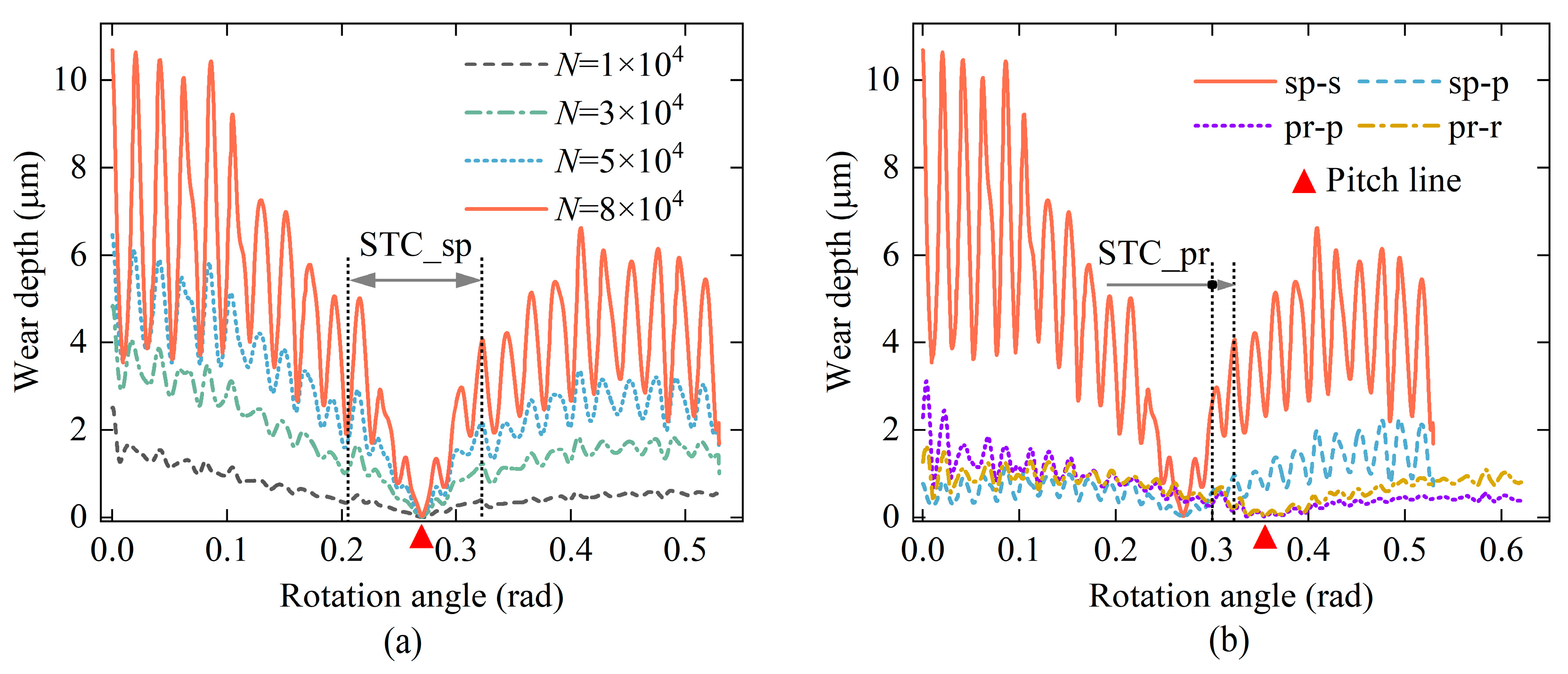
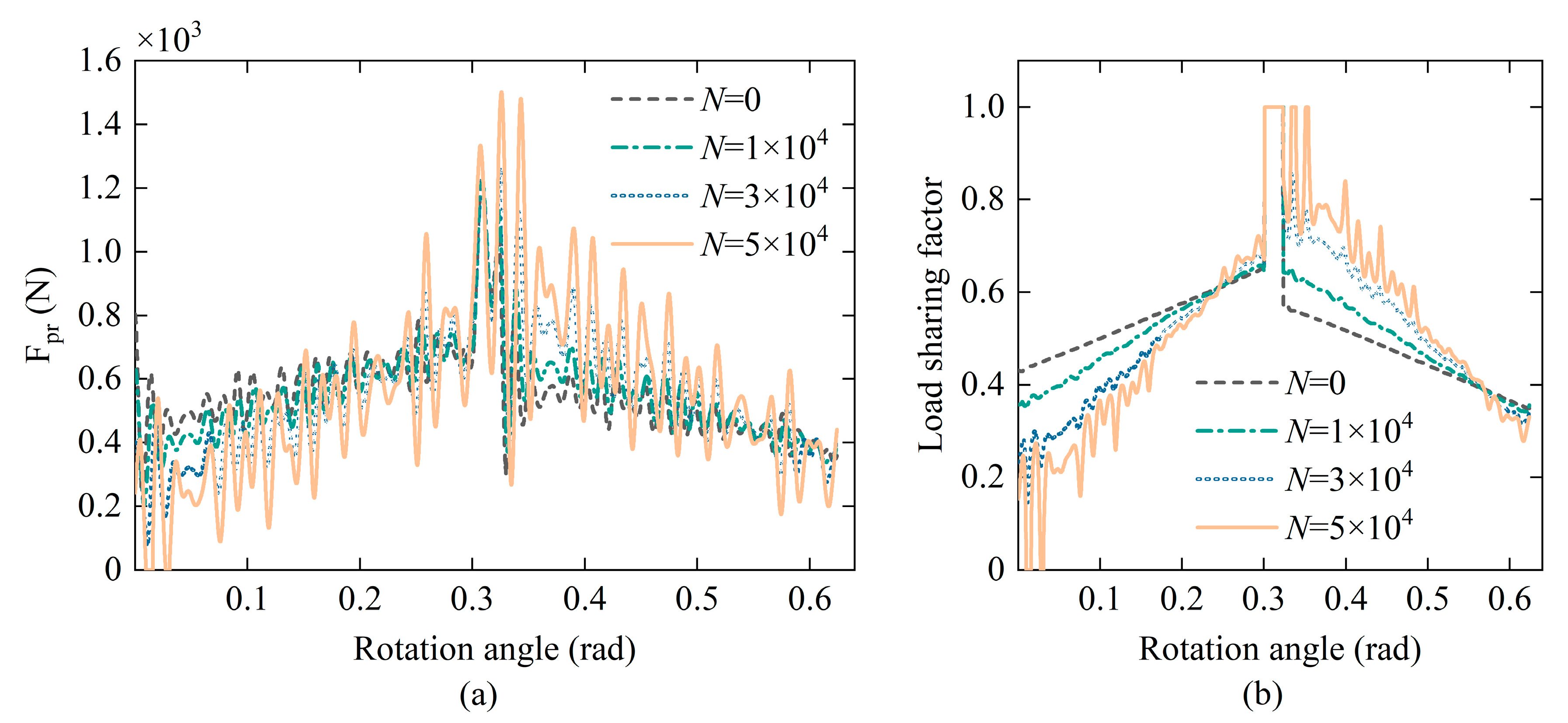
Wear causes different deformations of the two meshing gear teeth in the double tooth contact region, which results in a significant decrease in stiffness. And, the degree of fluctuation of TVMS and meshing force increases significantly with the evolution of wear. The load-sharing factor in the dedendum and addendum regions decreases as the tooth surface wears. The location of maximum wear depth is, thus, correspondingly moved slowly towards the pitch line.
(3)
Early wear is able to improve the dynamic performance of the system. Fluctuations in the gear ratio, vibration velocity, and transmission error are all mitigated. However, as wear increases, the dynamic performance of the system gradually deteriorates. This is mainly reflected in the significant increase in the higher harmonics of the meshing frequency.
(4)
The uniform load performance of planet gears in the system showed the same trend of change during wear as indicators such as transmission errors. A minor amount of wear did not change the equilibrium position of the system. However, the uniform load performance of planet gears decreases significantly as the wear increases. The standard deviation at N = 5 × 10⁴ reaches more than three times that without wear, and the amplitude increases by more than 80%.
Based on the above work, further experimental investigations will be carried out in subsequent studies. And, the evolution of the system performance under liquid lubrication conditions will be expanded to be considered.

Author Contributions

Conceptualization, J.C. and J.M.; Methodology, J.C.; Software, J.C. and N.D.; Validation, J.C., N.D., and J.M.; Formal analysis, J.C.; Investigation, J.C.; Resources, J.M.; Data curation, N.D.; Writing—original draft preparation, J.C.; Writing—review and editing, J.C.; Visualization, J.C. and N.D. All authors have read and agreed to the published version of the manuscript.

Funding

This research was funded by the Key R&D Program of Xinjiang Province (Grant No. 2022B01017).

Data Availability Statement

All the data are shown in the tables and figures of this paper.

Conflicts of Interest

The authors declare no conflict of interest.

References

  1. Cao, W.; Han, Z.; Yang, Z.Z.; Wang, N.; Qu, J.X.; Wang, D. Deterioration State Diagnosis and Wear Evolution Evaluation of Planetary Gearbox Using Vibration and Wear Debris Analysis. Measurement 2022, 193, 110978. [Google Scholar] [CrossRef]
  2. Feng, K.; Ji, J.C.; Ni, Q.; Beer, M. A Review of Vibration-Based Gear Wear Monitoring and Prediction Techniques. Mech. Syst. Signal Process. 2023, 182, 109605. [Google Scholar] [CrossRef]
  3. Lei, Y.; Lin, J.; Zuo, M.J.; He, Z. Condition Monitoring and Fault Diagnosis of Planetary Gearboxes: A Review. Measurement 2014, 48, 292–305. [Google Scholar] [CrossRef]
  4. Cooley, C.G.; Parker, R.G. A Review of Planetary and Epicyclic Gear Dynamics and Vibrations Research. Appl. Mech. Rev. 2014, 66, 040804. [Google Scholar] [CrossRef]
  5. Wang, X. A Study on Coupling Faults’ Characteristics of Fixed-Axis Gear Crack and Planetary Gear Wear. Shock. Vib. 2018, 2018, 4692796. [Google Scholar] [CrossRef]
  6. Dong, N.; Cui, Q.; Zhou, J.; Tong, R.; Wang, H.; Lu, F. Study on Wear Evolution of Spur Gears Considering Dynamic Meshing Stiffness. J. Mech. Sci. Technol. 2023, 37, 3393–3408. [Google Scholar] [CrossRef]
  7. Kuang, J.H.; Lin, A.D. The Effect of Tooth Wear on the Vibration Spectrum of a Spur Gear Pair. J. Vib. Acoust. 1999, 123, 311–317. [Google Scholar] [CrossRef]
  8. Sun, Y.; Li, Y.; Zhang, Q.; Qin, X.; Chen, K. Wear Analysis and Simulation of Small Module Gear Based on Archard Model. Eng. Fail. Anal. 2023, 144, 106990. [Google Scholar] [CrossRef]
  9. Matkovič, S.; Pogačnik, A.; Kalin, M. Wear-Coefficient Analyses for Polymer-Gear Life-Time Predictions: A Critical Appraisal of Methodologies. Wear 2021, 480–481, 203944. [Google Scholar] [CrossRef]
  10. Sánchez, M.B.; Pleguezuelos, M.; Pedrero, J.I. Influence of Profile Modification on the Transmission Error of Spur Gears under Surface Wear. Mech. Mach. Theory 2024, 191, 105473. [Google Scholar] [CrossRef]
  11. Chen, W.; Lei, Y.; Fu, Y.; Hou, L. A Study of Effects of Tooth Surface Wear on Time-Varying Mesh Stiffness of External Spur Gear Considering Wear Evolution Process. Mech. Mach. Theory 2021, 155, 104055. [Google Scholar] [CrossRef]
  12. Shen, Z.; Qiao, B.; Yang, L.; Luo, W.; Chen, X. Evaluating the Influence of Tooth Surface Wear on TVMS of Planetary Gear Set. Mech. Mach. Theory 2019, 136, 206–223. [Google Scholar] [CrossRef]
  13. Shen, Z.; Qiao, B.; Yang, L.; Luo, W.; Yang, Z.; Chen, X. Fault Mechanism and Dynamic Modeling of Planetary Gear with Gear Wear. Mech. Mach. Theory 2021, 155, 104098. [Google Scholar] [CrossRef]
  14. Yuksel, C.; Kahraman, A. Dynamic Tooth Loads of Planetary Gear Sets Having Tooth Profile Wear. Mech. Mach. Theory 2004, 39, 695–715. [Google Scholar] [CrossRef]
  15. Wojnarowski, J.; Onishchenko, V. Tooth Wear Effects on Spur Gear Dynamics. Mech. Mach. Theory 2003, 38, 161–178. [Google Scholar] [CrossRef]
  16. Kahraman, A.; Ding, H. A Methodology to Predict Surface Wear of Planetary Gears Under Dynamic Conditions. Mech. Based Des. Struct. Mach. 2010, 38, 493–515. [Google Scholar] [CrossRef]
  17. Inalpolat, M.; Kahraman, A. A Theoretical and Experimental Investigation of Modulation Sidebands of Planetary Gear Sets. J. Sound Vib. 2009, 323, 677–696. [Google Scholar] [CrossRef]
  18. Zhao, X.; Fan, W.; Wang, Z.; Wen, Z.; Wang, P. An Explicit Finite Element Approach for Simulations of Transient Meshing Contact of Gear Pairs and the Resulting Wear. Wear 2023, 523, 204802. [Google Scholar] [CrossRef]
  19. Sondkar, P.; Kahraman, A. A Dynamic Model of a Double-Helical Planetary Gear Set. Mech. Mach. Theory 2013, 70, 157–174. [Google Scholar] [CrossRef]
  20. Matejic, M.S.; Blagojevic, M.Z.; Matejic, M.M. Dynamic Behaviour of a Planetary Reducer with Double Planet Gears. Mech. Sci. 2021, 12, 997–1003. [Google Scholar] [CrossRef]
  21. Ouyang, T.; Huang, H.; Zhang, N.; Mo, C.; Chen, N. A Model to Predict Tribo-Dynamic Performance of a Spur Gear Pair. Tribol. Int. 2017, 116, 449–459. [Google Scholar] [CrossRef]
  22. Walker, J.; Mohammadpour, M.; Theodossiades, S.; Bewsher, S.R.; Offner, G.; Bansal, H.; Leighton, M.; Braunstingl, M.; Flesch, H.-G. A Multi-Physics Transient Wear Model for Helical Gear Pairs. Tribol. Int. 2022, 169, 107463. [Google Scholar] [CrossRef]
  23. Wang, H.; Zhou, C.; Hu, B.; Li, Y. An Adhesive Wear Model of Rough Gear Surface Considering Modified Load Distribution Factor. Proc. Inst. Mech. Eng. Part J J. Eng. Tribol. 2022, 236, 2162–2179. [Google Scholar] [CrossRef]
  24. Liu, H.; Liu, H.; Zhu, C.; Wei, P.; Tang, J. Tribological Behavior of Coated Spur Gear Pairs with Tooth Surface Roughness. Friction 2018, 7, 117–128. [Google Scholar] [CrossRef]
  25. Mao, Y.; Tong, J.; Chin, Z.Y.; Borghesani, P.; Peng, Z. Transmission-Error- and Vibration-Based Condition Monitoring of Gear Wear with Contaminated Lubricant. Wear 2023, 523, 204760. [Google Scholar] [CrossRef]
  26. Masjedi, M.; Khonsari, M.M. An Engineering Approach for Rapid Evaluation of Traction Coefficient and Wear in Mixed EHL. Tribol. Int. 2015, 92, 184–190. [Google Scholar] [CrossRef]
  27. Li, X.; Xu, J.; Yang, Z.; Chen, R.; Yang, H. The Influence of Tooth Surface Wear on Dynamic Characteristics of Gear-Bearing System Based on Fractal Theory. J. Comput. Nonlinear Dyn. 2020, 15, 041004. [Google Scholar] [CrossRef]
  28. Wang, T.; Han, Q.; Chu, F.; Feng, Z. Vibration Based Condition Monitoring and Fault Diagnosis of Wind Turbine Planetary Gearbox: A Review. Mech. Syst. Signal Process. 2019, 126, 662–685. [Google Scholar] [CrossRef]
  29. Xu, L.; Ding, K.; He, G.; Li, Y.; Chen, Z. Resonance Modulation Vibration Mechanism of Equally-Spaced Planetary Gearbox with a Localized Fault on Sun Gear. Mech. Syst. Signal Process. 2022, 166, 108450. [Google Scholar] [CrossRef]
  30. Zhang, M.; Zuo, M.J.; Wei, D.; Liu, J.; Wang, K.; Wang, Y. Motion Periods of Sun Gear Dynamic Fault Meshing Positions in Planetary Gear Systems. Measurement 2020, 162, 107897. [Google Scholar] [CrossRef]
  31. Liu, X. Vibration Modelling and Fault Evolution Symptom Analysis of a Planetary Gear Train for Sun Gear Wear Status Assessment. Mech. Syst. Signal Process. 2022, 166, 108403. [Google Scholar] [CrossRef]
  32. Dai, H.; Chen, F.; Xun, C.; Long, X. Numerical Calculation and Experimental Measurement for Gear Mesh Force of Planetary Gear Transmissions. Mech. Syst. Signal Process. 2022, 162, 108085. [Google Scholar] [CrossRef]
  33. Luo, W.; Qiao, B.; Shen, Z.; Yang, Z.; Cao, H.; Chen, X. Influence of Sliding Friction on the Dynamic Characteristics of a Planetary Gear Set With the Improved Time-Varying Mesh Stiffness. J. Mech. Des. 2020, 142, 073302. [Google Scholar] [CrossRef]
  34. Zhang, K.; Li, H.; Cao, S.; Wang, C.; Sun, B.; Liu, A. Investigation on Planetary Gearbox Fault Mechanism under Variable Speed Conditions Based on Rigid-Flexible Coupling Dynamics Model. Eng. Fail. Anal. 2022, 133, 105994. [Google Scholar] [CrossRef]
  35. Tian, H.; Han, H.; Zhao, Z.; Han, C.; Ma, H. Wear Prediction and Meshing Characteristics for the Planetary Gear Set Considering Angular Misalignment and Rotating Carrier. Eng. Fail. Anal. 2022, 140, 106583. [Google Scholar] [CrossRef]
  36. Feng, K.; Smith, W.A.; Peng, Z. Use of an Improved Vibration-Based Updating Methodology for Gear Wear Prediction. Eng. Fail. Anal. 2021, 120, 105066. [Google Scholar] [CrossRef]
  37. Feng, K.; Borghesani, P.; Smith, W.A.; Randall, R.B.; Chin, Z.Y.; Ren, J.; Peng, Z. Vibration-Based Updating of Wear Prediction for Spur Gears. Wear 2019, 426–427, 1410–1415. [Google Scholar] [CrossRef]
  38. Feng, K.; Smith, W.A.; Randall, R.B.; Wu, H.; Peng, Z. Vibration-Based Monitoring and Prediction of Surface Profile Change and Pitting Density in a Spur Gear Wear Process. Mech. Syst. Signal Process. 2022, 165, 108319. [Google Scholar] [CrossRef]
  39. Sainsot, P.; Velex, P.; Duverger, O. Contribution of Gear Body to Tooth Deflections—A New Bidimensional Analytical Formula. J. Mech. Des. 2004, 126, 748–752. [Google Scholar] [CrossRef]
  40. Pedrero, J.I.; Pleguezuelos, M.; Sánchez, M.B. Influence of Meshing Stiffness on Load Distribution between Planets of Planetary Gear Drives. Mech. Mach. Theory 2022, 170, 104718. [Google Scholar] [CrossRef]
Figure 1. Schematic diagram for 2K-H planetary gear system.
Machines 11 00986 g001
Figure 2. Schematic diagram of subsystem structure: (a) sun-planet substructure; (b) planet-carrier substructure; (c) planet-ring substructure.
Machines 11 00986 g002
Figure 3. Gear tooth model with wear error.
Machines 11 00986 g003
Figure 4. Schematic diagram of average contact pressure.
Machines 11 00986 g004
Figure 5. Schematic diagram of gear tooth contact.
Machines 11 00986 g005
Figure 6. Flowchart for solving coupled wear and dynamics.
Machines 11 00986 g006
Figure 7. Diagram of the experimental equipment.
Machines 11 00986 g007
Figure 8. Friction coefficient with different operating conditions.
Machines 11 00986 g008
Figure 9. Cross-sectional profile of wear marks.
Machines 11 00986 g009
Figure 10. TVMS of gear pairs in the system.
Machines 11 00986 g010
Figure 11. Comparison between considering only sun gear wear and taking into account all gear wear: (a) Wear depth of the sun gear. (b) Vibration velocity along the x-direction of the sun gear.
Machines 11 00986 g011
Figure 12. Comparison of dynamic transmission errors for different calculation methods.
Machines 11 00986 g012
Figure 13. Comparison of results with and without friction: (a) wear depth of the sun gear, (b) vibration velocity along the x-direction of the sun gear.
Machines 11 00986 g013
Figure 14. Dynamic transmission error with and without friction.
Machines 11 00986 g014
Figure 15. Wear depths at different wear cycles: (a) sun wheel, (b) wear of all tooth surfaces at N = 8 × 10⁴.
Machines 11 00986 g015
Figure 16. Gear ratios with different wear cycles.
Machines 11 00986 g016
Figure 17. Load carrying of sun-planet gear pair at different wear cycles: (a) meshing force, (b) load-sharing factor.
Machines 11 00986 g017
Figure 18. Load carrying of planet-ring gear pair under different wear cycles: (a) meshing force, (b) load-sharing factor.
Machines 11 00986 g018
Figure 19. TVMS of the system for different wear cycles.
Machines 11 00986 g019
Figure 20. Vibration velocity of the sun gear along the x-direction for different wear cycles.
Machines 11 00986 g020
Figure 21. Dynamic transmission error of sun-planet meshing pair under different wear periods.
Machines 11 00986 g021
Figure 22. Frequency domain diagram of dynamic transmission error.
Machines 11 00986 g022
Figure 23. Load sharing coefficients of planet gears for different wear cycles.
Machines 11 00986 g023
Table 1. Parameters of the planetary gear set.
ParametersSun GearPlanet GearRing Gear
Module (mm)2
Number of teeth253187
Pressure angle (°)20
Face width (mm)20
Modification coefficientxm = 0
Tip clearance coefficientc* = 0.25
Addendum coefficientha* = 1
Elastic modulus (GPa)207
Poisson’s ratio0.29
Mass (kg)0.26110.43711.0416
Moment of inertia (kg·m2)9.4 × 10−52.4 × 10−40.0048
Table 2. Parameters of the wear test.
ParametersSpecimenBall
Modulus of elasticity (GPa)207207
Density (kg/m3)78507850
Surface roughness (μm)0.80.8
Size (mm)30 (L) × 7 (W) × 7 (H)Diameter = 9
Table 3. Wear coefficients for different operating conditions.
30 N3 Hz
2 Hz3 Hz4 Hz5 Hz10 N30 N50 N70 N
Wear coefficient (×10−15)2.741.671.191.831.791.671.751.49
Table 4. Statistical analysis of the vibrational velocity for the sun gear.
N = 0N = 1 × 10⁴N = 3 × 10⁴N = 5 × 10⁴
ValueErrorValueErrorValueErrorValueError
std0.008700.0073−16.1%0.010419.5%0.0206136.8%
max0.025400.0245−3.5%0.0249−2.0%0.044976.8%
min−0.02530−0.0234−7.5%−0.031725.3%−0.045479.4%
Table 5. Statistical analysis of load-sharing coefficients.
N = 0N= 1 × 10⁴N = 3 × 10⁴N= 5 × 10⁴
ValueErrorValueErrorValueErrorValueError
mean0.250000.25000.0%0.2498−0.1%0.2491−0.4%
std0.016800.0165−1.8%0.032895.2%0.0717326.8%
max0.304600.30550.3%0.33008.3%0.400731.5%
min0.200900.19542.7%0.169415.7%0.088855.8%
Disclaimer/Publisher’s Note: The statements, opinions and data contained in all publications are solely those of the individual author(s) and contributor(s) and not of MDPI and/or the editor(s). MDPI and/or the editor(s) disclaim responsibility for any injury to people or property resulting from any ideas, methods, instructions or products referred to in the content.

