Article

Crowning Method on Bearing Supporting Large Wind Turbine Spindle Considering the Flexibility of Structure of Shaft System

1
School of Mechatronics Engineering, Henan University of Science and Technology, Luoyang 471003, China
2
China State Shipbuilding Corporation Haizhuang Wind Power Co., Ltd., Chongqing 401123, China
3
School of Mechanical Engineering, Henan Institute of Technology, Xinxiang 453003, China
*
Author to whom correspondence should be addressed.
Machines 2023, 11(1), 28; https://doi.org/10.3390/machines11010028
Submission received: 22 November 2022 / Revised: 21 December 2022 / Accepted: 22 December 2022 / Published: 26 December 2022
(This article belongs to the Topic Designs and Drive Control of Electromechanical Machines)

Abstract

:
To meet the precision design of bearings on large wind turbine spindles, a crowning method of bearing on wind turbine spindles considering the flexibility of the support structure is proposed. Firstly, a finite element (FE) model of the shaft system with a flexible structure is constructed by connecting the shaft and bearing through constraint equations (CE) and multi-point constraint (MPC) algorithms and replacing the bearing rollers with nonlinear spring elements and dampers. Then, the Newmark integration algorithm is used to solve the model and analyze the effect of the structure’s rigidity on the load distribution of bearings. Then, perform convergence analysis of the sequences of the spring load distribution using a high-pass filter based on fast Fourier transform (FFT) and root mean square error (RMSE) to obtain a suitable number of replacement springs. Finally, a sub-model of the upwind bearing is constructed with structured mesh. With the maximum Von Mises stress of the roller profile as the design target, the optimal logarithmic crowning of the roller and its tolerance zone under the given working conditions are obtained. The results show that the FE model of the shaft system proposed has good convergence. The FE model of the shaft system considering the flexibility of the support structure can obtain more accurate load distributions of bearings and can make the accurate crowning design of the bearing rollers based on the actual working conditions. This provides support for the precision design of bearings in large shaft systems.

1. Introduction

To solve the problem of energy shortage and environmental pollution, wind turbines are deployed in large numbers around the world. The bearings on the wind turbine spindle are the key rotary parts of wind power equipment, and their failure will cause great economic losses [1,2]. Because the bearings on wind turbine spindles are usually installed in pairs, the actual load of a single bearing is difficult to measure. At present, the traditional design theory of bearing is to use the design formula or experience to design a single bearing according to the given design load, but the structural flexibility of the shaft system cannot be considered in the design. In a shaft assembly, the contact stress distribution of bearing rollers designed by this method is not optimal and cannot meet the accuracy requirements. The finite element method (FEM) can consider the structural flexibility result by constructing the overall model of the shaft assembly, which can obtain a more accurate bearing load and stress distribution under the global load. It has higher calculation accuracy than the traditional design theory of bearing and can be used for the precision design of bearings in complex assembly. However, due to the large size, complex structure, and the large number of rollers of bearings on the wind turbine spindle, the FE analysis of it needs to include two sets of bearings and support structure at the same time, it is very difficult to carry out FE analysis. Therefore, the reliability design of large-size bearings, such as bearings on wind turbine spindles, has become increasingly prominent.
For the design and analysis of large-size bearings, the simplified FE method is now widely used by scholars. Smolnicki et al. [3] proposed a superelement-based FE model for large bearings, using superelements instead of the nonlinear contact actions between rollers and raceways, while the rings of the bearings are still modeled using solid elements. Chen et al. [4,5] used extension spring elements to replace the balls of a wind turbine pitch turntable bearing to analyze the effects of the rigidity of the support structure, the number of bolts, and the preload force on the bearing life. The effect of hub rigidity on the bearing load distribution was also analyzed. Plaza et al. [6] replaced the nonlinear contact actions between the balls and raceways of the pitch turntable bearing with extension spring elements and used superelements to model the rings of the bearing, thus significantly reducing the computational effort. Li et al. [7] proposed an equivalent FE modeling method to analyze the bearing and mounting structure by replacing the balls with nonlinear extension spring elements and using beam elements instead of solid mounting bolts. Aguirrebeitia et al. [8] developed a FE model of a four-point contact ball bearing based on nonlinear spring elements and calculated the static load-carrying capacity of the bearing, which was verified by comparing with the theoretical results, pointing out that the results of the FE model are more accurate than the theoretical results and the theoretical solution is more conservative. He et al. [9] used nonlinear springs instead of solid rollers to study the effect of raceway hardening on slewing bearing life. The use of nonlinear springs enabled the model to obtain results quickly. Śpiewak et al. [10] developed both a FE model and a theoretical analytical model of a double slewing bearing and verified them in comparison. It was suggested to replace each roller with one or more truss elements in the FE model of the bearing. To reduce the calculation scale of wire bearings in FEM, Martín et al. [11] proposed the method based on a custom matrix element and the replacement-element method for a roller based on a nonlinear spring element, among which the former has higher accuracy and the latter has a simpler operation process. The above studies have shown that the use of simplified elements instead of solid rollers in the analysis of bearings by the FEM can significantly reduce the calculation effort and has good accuracy, which is widely used in the analysis of large-size bearings.
The working load of bearings on large wind turbine spindles is extremely high. The profile of the roller or raceway has a direct impact on the stress distribution of the roller and the life of the bearing. The modification of the profile of the raceway or roller can optimize the load distribution. Kania [12] proposed a method for modification of the raceway profile of four-point contact rotary table bearings in a wind turbine, which improved the load-carrying capacity of bearings. However, compared with crowned rollers, this method increases the technical difficulty and production cost. Ju et al. [13] studied the effect of the power function profile and exponential profile on the stress concentration of bearing rollers and pointed out that the exponential profile can effectively reduce the stress concentration, but the unsmooth connection between the straight line of the roller and the exponential trim line is still prone to sudden stress changes. Fujiwara [14] and He [15] offered a method to study the optimal crowning amount of a logarithmic crowned roller, and the optimal crowning function was obtained by adjusting the control coefficient of load and control coefficient of contact. Based on the nonlinear equation of elastic contact, Li [16] established a numerical model of tapered roller bearings on wind turbine spindles and analyzed the load distribution of bearing with logarithmic crowned rollers, pointing out that the logarithmic crowning is widely accepted by bearing manufacturers. Zhang et al. [17] analyzed the effects of load, tilting angle, and the crowning curve of the roller on the stress distribution of rollers of three-row cylindrical roller turntable bearings in wind turbines, and proposed a crowning method using logarithmic curve and tangent arc for axial and radial rollers, respectively, based on the load characteristics of turntable bearings. Li et al. [18] constructed an overall model and a sub-model for a wind turbine with a large taper angle, respectively. The overall model analyzed the effect of axial bearing clearance on the load distribution of bearing, the sub-model analyzed the effect of different crowning shapes on the contact stress of the roller, and the use of simplified FEM greatly reduced the computational effort. The logarithmic crowning curve was found to enable the bearing to have a high load-carrying capacity under the studied working conditions. The above researches show that the logarithmic crowning makes the stress on the roller profile uniformly distributed under the non-extreme bias load condition, which is the optimal crowning method at present.
At present, the analysis of large-size bearings is widely focused on the analysis of individual bearings. For bearings on large wind turbine spindles, more accurate load distribution can be obtained by constructing a FE model of the shaft system, but the analysis type of the above traditional simplified method is still nonlinear, and the model is more difficult to converge after coupling the bearing further to the shaft system. The research of [17] considered the effect of mounting bolts on the load distribution of bearings but assumed that the design load of the bearing was known. The research of [4,5] established a FE model of a turntable bearing with a flexible support structure and investigated the effect of the rigidity of the support structure on the bearing life. However, the support structure is directly coupled to a single bearing and is not applicable to shaft systems of wind turbine spindles containing multiple sets of bearings. The research of [18] established a FE model of a flexible shaft system to analyze the bearings, but the coupling method of the FE model was not introduced in detail. To sum up, there is a lack of relevant literature on the design of spindle bearing considering the structure flexibility of complex shaft systems like large wind turbine spindles by using FEM.
In view of this, considering the flexibility of the support structure of the shaft system, a FE model of the shaft system of the wind turbine spindle is established based on CE, MPC algorithm, and nonlinear spring elements in ANSYS® 2020 R2 software. The critical damping technique is used to improve the convergence of the model. A FE modeling method with good convergence for the shaft system is proposed, which can obtain the accurate load distribution of the bearings by the external wind load of the shaft system and can optimize the bearing roller profile directly. Then the bearing sub-model with structured mesh is constructed. The design method of roller crowning’s tolerance of large bearing is given with logarithmic crowning parameters as design variables and the maximum stress along the profile of the roller at the center of the contact area as the design target. The analysis flow of the work is shown in Figure 1.

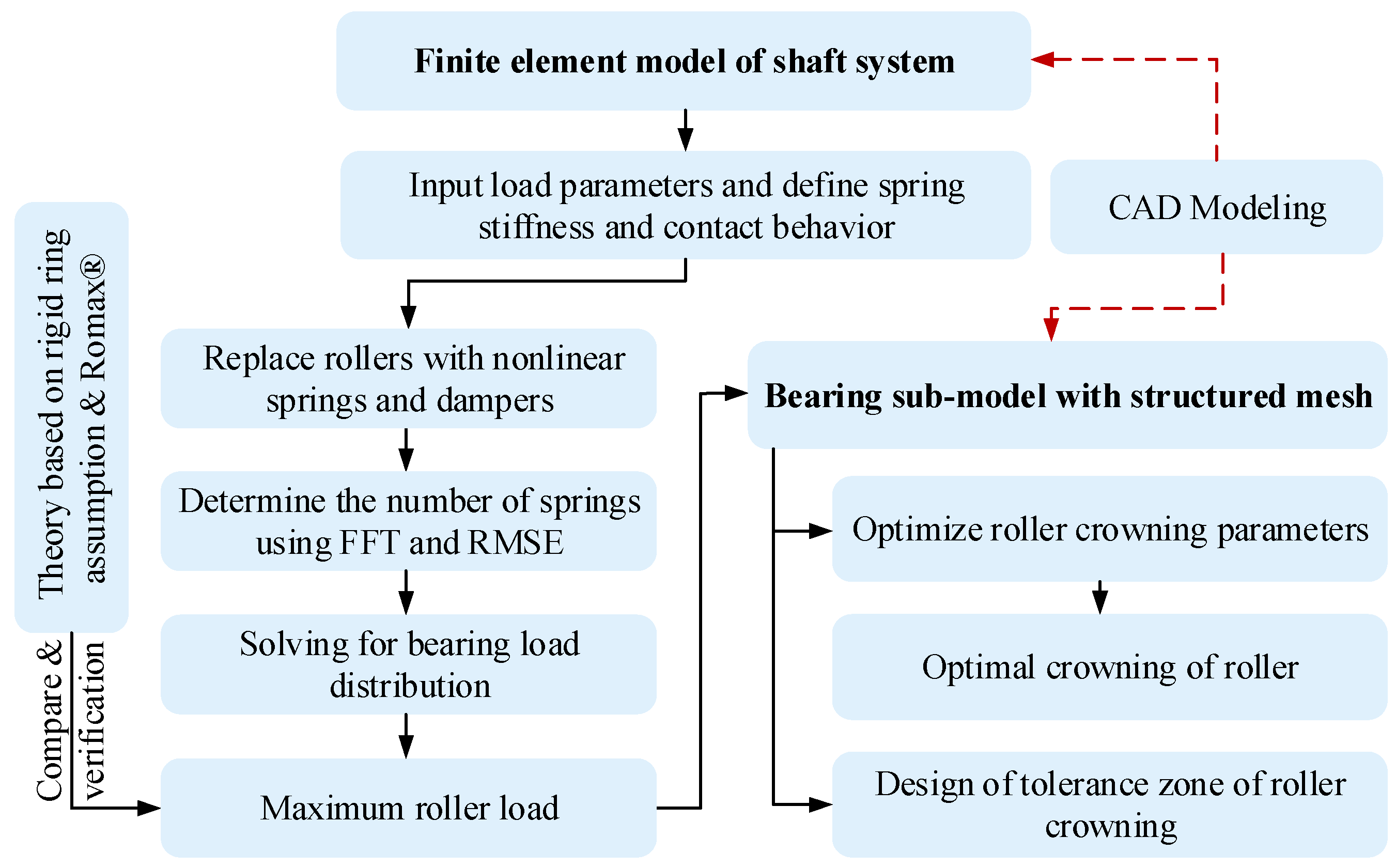
2. FE Modeling Method of the Shaft Assembly

The main shaft assembly of a 6.25 MW wind turbine is used as the study object, and the installation structure consists of two sets of tapered roller bearings, a main shaft, and a bearing housing, as shown in Figure 2. The wind load is transmitted to the bearing through the hub and shaft, where L1 = 2500 mm and L2 = 2100 mm. Do not consider the effect of heat treatment and other effects on the material of the shaft, bearing, and housing in the analysis, using the same metal material parameters with a density of 7850 kg·m−3, an elastic modulus of 2.1 × 10¹¹ Pa, and a Poisson’s ratio of 0.3. The structural parameters of the bearings are shown in Table 1. The wind load parameters are shown in Table 2.

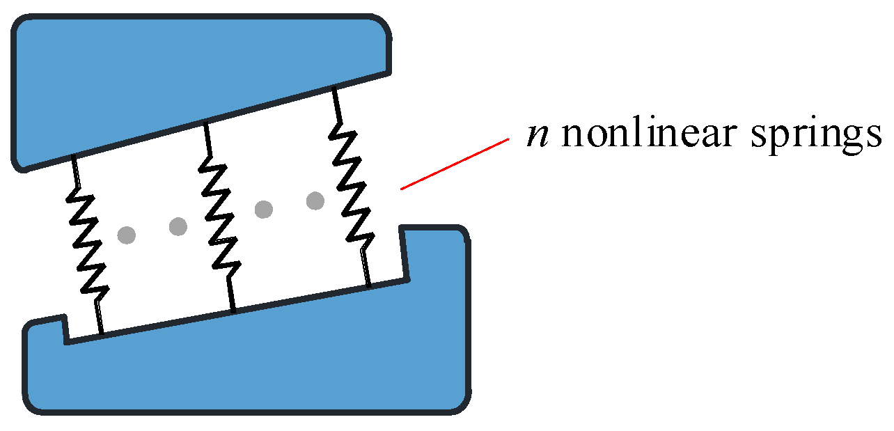
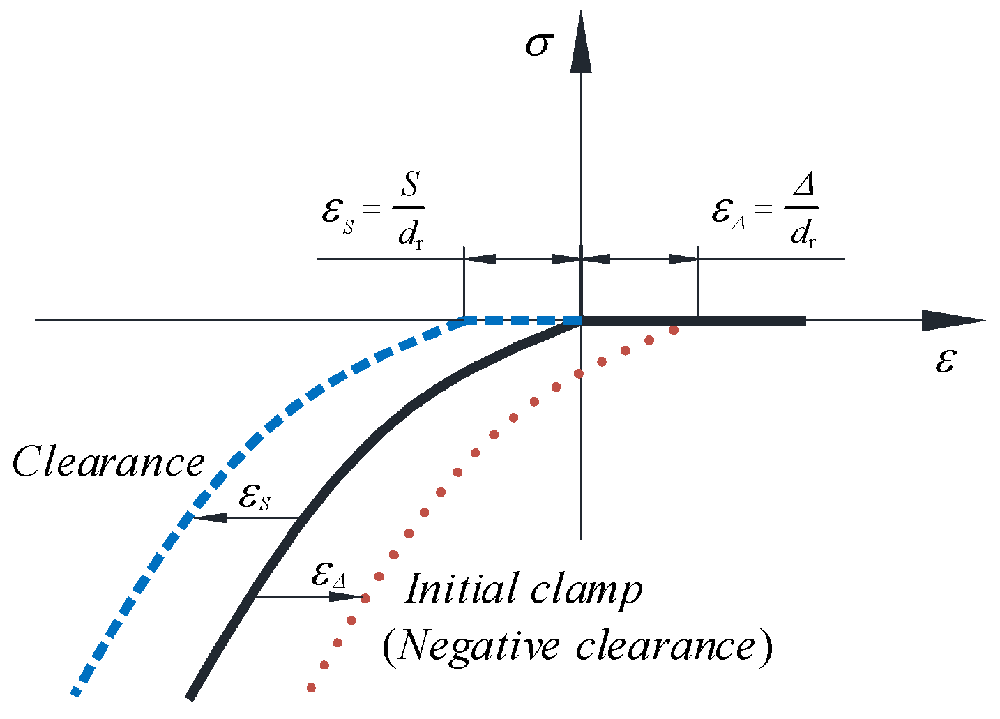
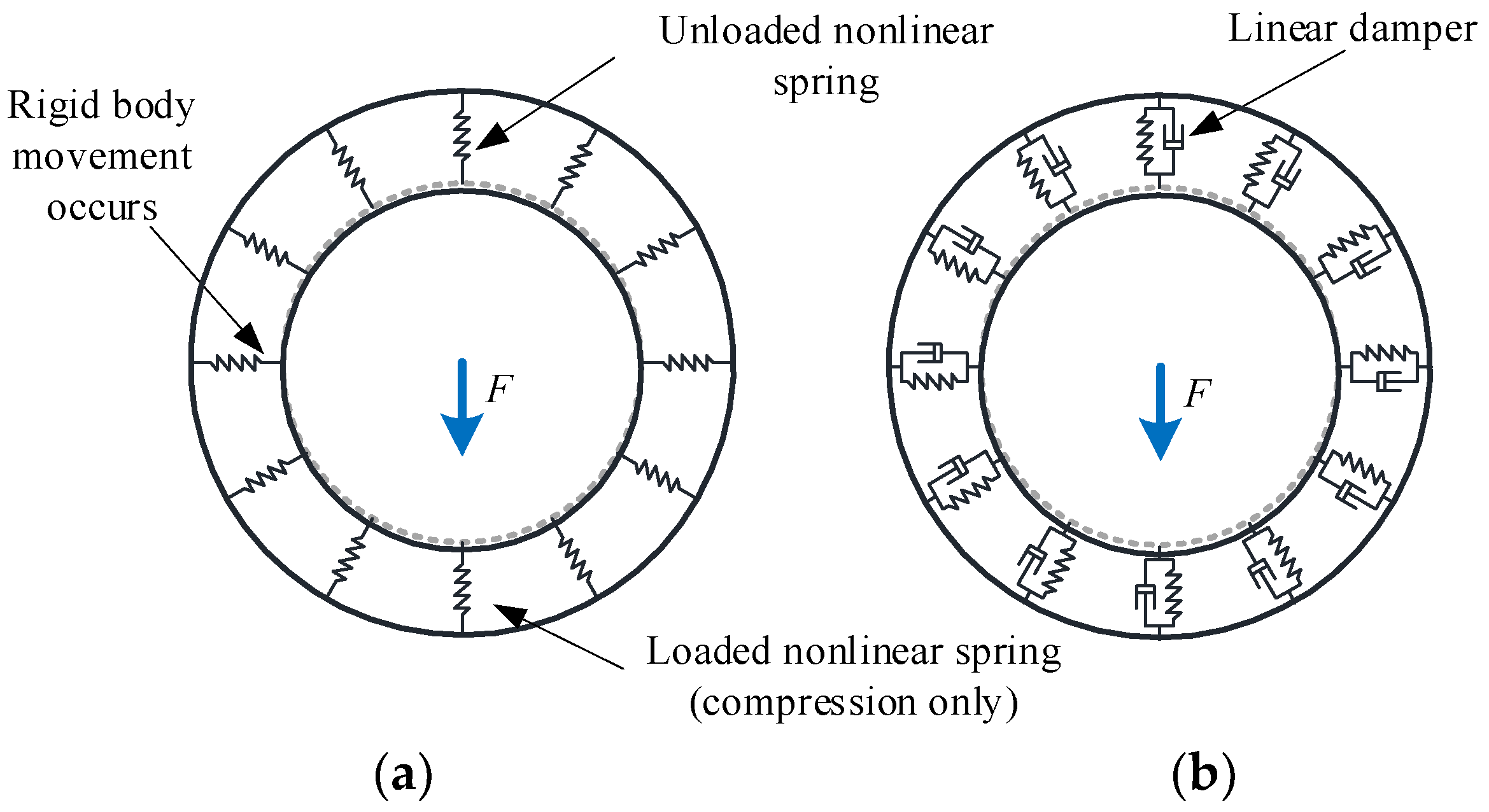
2.1. Bearings Modeling

Due to the large size of bearings on the wind turbine spindle and the large number of rollers, it will generate massive nonlinear contact calculations if the solid elements are used to model the rollers. Meanwhile, it will introduce extremely strong nonlinearity to the FE model, which results in difficulty in solving the model.
In FE analysis of large-size bearings, modeling the rings with three-dimensional solid elements and the rollers with one-dimensional nonlinear elements can significantly reduce the computational effort. The simplification methods widely used are [4,5,6,19,20].
  • Nonlinear spring elements with special nonlinear stress-strain characteristics.
  • Superelements with the reduction matrix of structural stiffness.
Replacing rollers with nonlinear spring elements can significantly reduce the number of elements, and speed up the discrimination calculation of the contact algorithm. Compared with the superelement, it is more convenient to operate, so the nonlinear spring elements are adopted to replace the bearing rollers. The connection method is shown in Figure 3.
Nonlinear spring elements mainly consist of nonlinearity of state (Compressed Only) and nonlinearity of material (Load-deformation Curve). The nonlinearity of state allows the spring elements to better simulate the real physical contact process of rollers, and the nonlinearity of material allows the spring elements to accurately describe the stress-strain relationship of rollers. For ball bearings, each ball of the bearing can be replaced by one spring element, the length of which is equal to the diameter of the ball. For roller bearings, each roller should be replaced by two or more spring elements to simulate the bias load on the roller. The higher the number of spring elements replacing a roller, the closer the calculated result is to the actual one.
The larger the error of the FE model, the larger the fluctuation of the distribution curve of the spring reaction. To quantitatively determine the appropriate number of replacement springs, the root mean square error (RMSE) of the load distribution is used as an evaluation indicator to obtain the ideal number of replacement springs. The RMSE is the standard deviation, and the RMSE is very sensitive to the deviation of the data and can reflect the accuracy of the measured data. The smaller the value of the RMSE, the higher the accuracy of the measured value, so the RMSE can be used to evaluate the accuracy of the measured value.
For bearings on wind turbine spindles, the ideal load distribution has one peak value and is smooth. The sequence of spring reaction force distribution has the same low-frequency component, and the distribution of spring reaction force fluctuates irregularly along the ideal distribution due to the FE model error.
The sequence of the reaction force distribution X of a series of springs is
X = x 1 , x 2 , , x Z
The high-frequency fluctuation characteristic sequence XF of the data can be obtained by filtering sequence X with a high-pass filter based on FFT.
X F = x F 1 , x F 2 , , x F Z
Then the RMSE of sequence X is
RMSE = i = 1 Z X i X ¯ F 2 Z
where Z is the number of bearing rollers and X ¯ F is the mean value of the sequence XF.
Figure 4 shows the stress-strain characteristics of the nonlinear truss elements in the FE analysis, where εS(Δ) is the strain under the action of clearance S and clamp Δ. The truss element has a defined length dr and cross-section, while the special material properties σ(ε) can be defined, and such an element can be used as a nonlinear spring element [9,16]. The clearance of the bearing in the FE analysis can be achieved directly by translating the material property curve of the truss element as shown in Figure 4 along the transverse axis.
The mechanical properties of a roller can be simulated by assigning the stiffness curve of the roller to nonlinear spring elements. The contact type of tapered roller bearings is line contact. According to the Hertzian contact theory, the relationship between the contact load and the contact elastic deformation of the roller is [21]
Q = K n δ 1.11
where Kn is the total load-deformation constant between the roller and ring; δ is the total elastic deformation of the roller and two rings.
Palmgren gave a formula for calculating the elastic deformation of line contact [22].
Q = 0.71 l 0.89 η δ 1.11
where l is the length of the roller, η is the combined elastic constant of two bodies in contact, and the formula is
η = 1 μ 1 2 E 1 + 1 μ 2 2 E 2
where μ 1 ( 2 ) is Poisson’s ratio of the two bodies and E 1 ( 2 ) is the elastic modulus of the two bodies.
Comparing Equations (4) and (5), the load-deformation constant (N/mm10/9) between the roller and the rings is
K n = 0.71 l 0.89 η
The stiffness curve of the tapered roller can be approximated by Equations (4) and (7).
Assuming that each roller is replaced by n nonlinear spring elements, the load-deformation constant for each spring element is
K spr = K n n
For the FE model of the whole shaft system, the nonlinear spring elements in the critical loading state perform rigid body movement, which may cause the singular stiffness matrix and make the FE model not converge. Such a simplified method is not very suitable for the FE analysis of large and complex structures. The use of critical damping technology based on nonlinear spring elements can realize the process of slow dynamic loading, i.e., a linear damper is established at the position of each nonlinear spring element, and the existence of the damper has no effect on the strain energy of the model and does not affect the solution accuracy. At the same time, the Newmark integration algorithm is used to solve the FE model by incremental integration method, and stable convergence results can be obtained quickly. The critical damping coefficient is determined by [23,24]
c = 2 k m
where c is the critical damping constant, Ns/m; k is the stiffness of spring, N/m; m is the mass of roller, kg.
The method of replacing the rollers with nonlinear spring elements and linear dampers is shown in Figure 5.

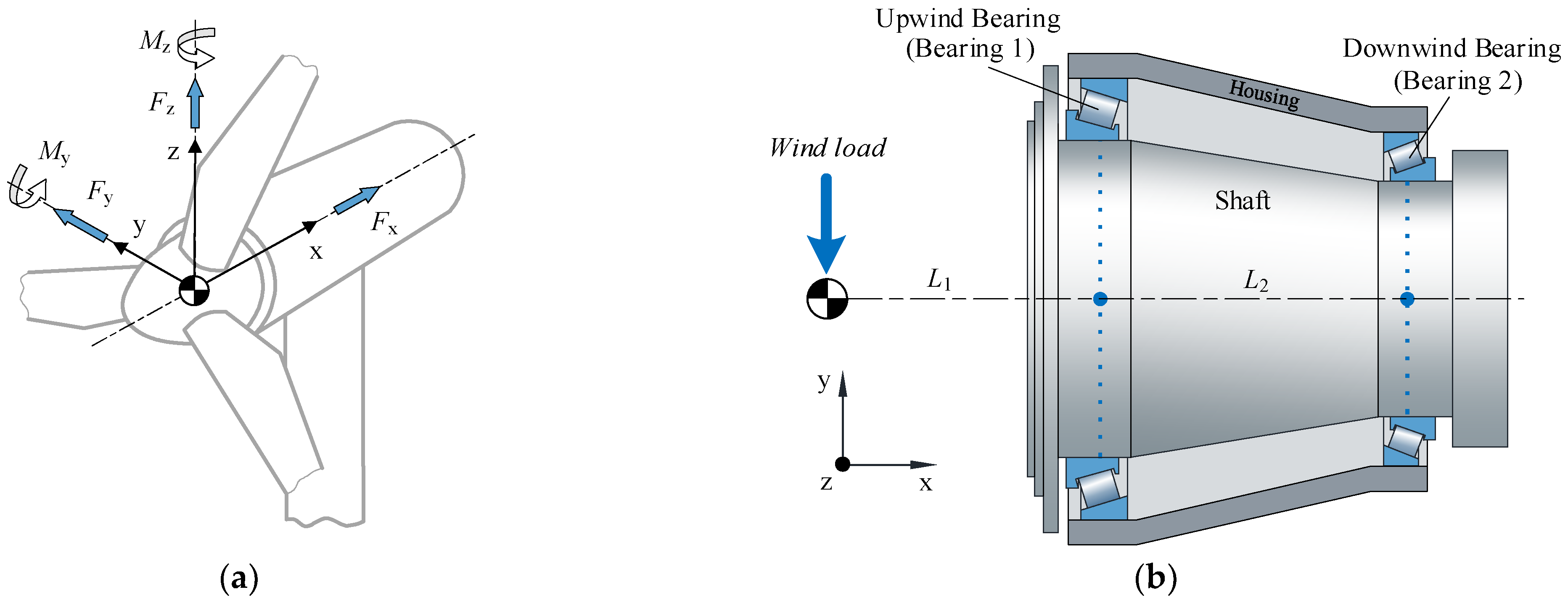
2.2. Main Shaft Modeling

The wind load is mainly distributed to the two support bearings through the main shaft, and the flexural deformation of the main shaft has a great influence on the load distribution of the bearings. Modeling of the main shaft with flexible beam elements. The bore surface of each bearing is coupled to a master node I at the center of the inner diameter surface through the CE. The MPC algorithm was used to constrain the degrees of freedom between the master node I and node J on the flexible beam, and the axial rotational degrees of freedom are simultaneously constrained to prevent shaft rotation. The wind load will be transferred to the bearing bore surface through the flexible beam. The shaft is connected to any of the bearings as shown in Figure 6, where qI and qJ are the coordinate systems of degrees of freedom of the I and J nodes. The I and J nodes both have six degrees of freedom, and the I and J nodes spatially overlap.
The degree of freedom constraint relationship of the two coupled nodes can be expressed as
C q I , q J , t = 0
where qI and qJ are the degrees of freedom corresponding to the coordinate system of degrees of freedom of the coupled nodes and t is the time.

2.3. Housing Modeling

In a wind turbine, the outer casing acts as the bearing housing for the bearings on the main shaft. The wind load is finally transferred to the outer casing through the shaft and bearings. The bearing housing holds the bearings on the spindle in place. Its elastic deformation under load affects the relative position of the outer rings of the bearings, and its flexibility directly affects the load distribution of the bearings just like that of the spindle. Ignoring its flexibility will result in too large spindle stiffness, which makes the calculation of the bearing load distribution inaccurate. Therefore, it is necessary to establish a flexible housing in the model. So the outer housing is modeled with 3D solid elements. To avoid the excessive introduction of nonlinearity in the system, the outer casing is coupled to the bearings’ outer rings by sharing nodes.
The shaft, bearing rings, and rollers are assembled and the final FE connection method is shown in Figure 7.
For a roller, at least two springs are required to simulate tilt or offset load. To study the effect of the number of replacement springs on the load distribution of bearing rollers, each roller is replaced by 2, 3, and 5 nonlinear spring elements (denoted as 2 spr, 3 spr, and 5 spr), respectively, corresponding to the partial view of the model shown in Figure 8. It contains n × (Z1 + Z2) nonlinear spring elements, n × (Z1 + Z2) linear dampers, and 2 MPC elements.

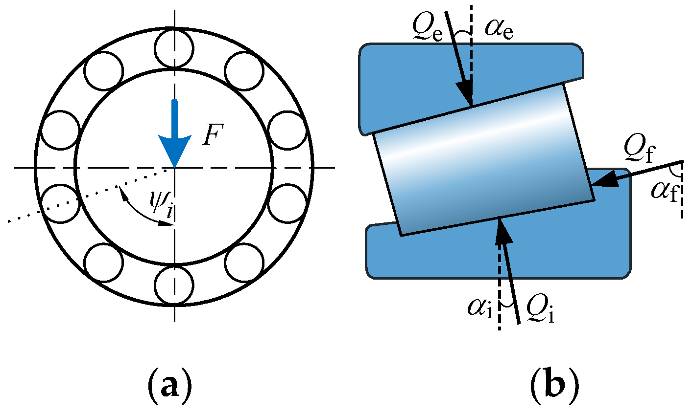
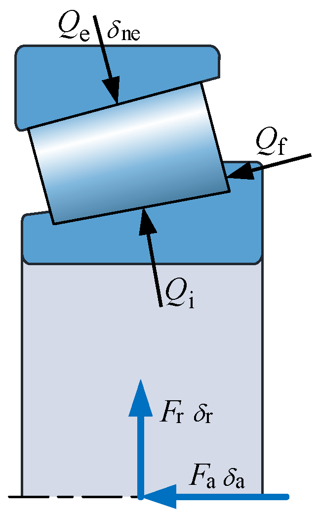
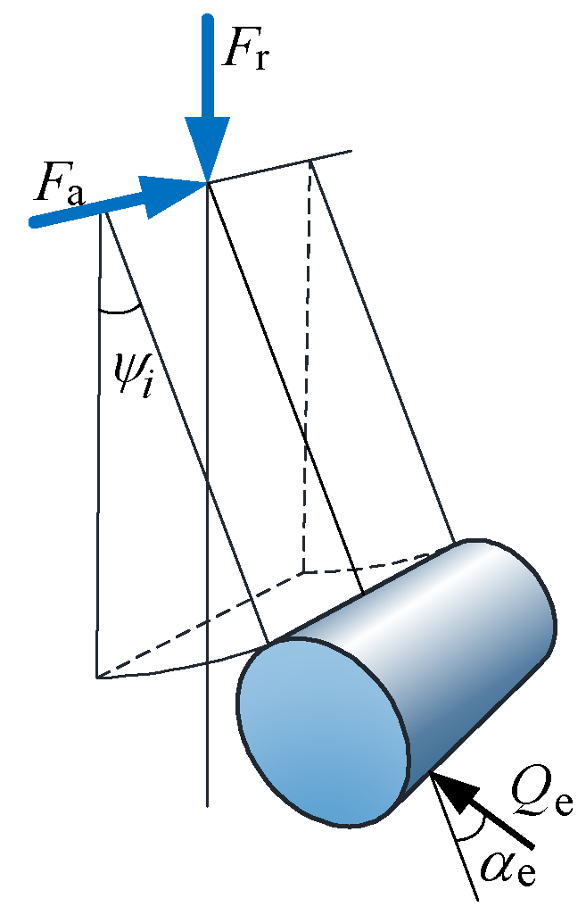
3. Theoretical Calculation of Maximum Roller Load

Figure 9 shows the cross-section of bearings on the wind turbine spindle. Under the action of external load, the contact loads between the tapered roller and the inner raceway, outer raceway, and end-ring flange are Qi, Qe, and Qf, respectively, and the contact angles are αi, αe, and αf, respectively. The roller load satisfies the following equilibrium equation.
Q e sin α e Q i sin α i Q f sin α f = 0 Q e cos α e Q i cos α i Q f cos α f = 0
It is further deduced that:
Q i = Q e sin α e + α f sin α i + α f = c i Q e
Q f = Q e sin α e α f sin α i + α f = c f Q e
where
c i = sin α e + α f sin α i + α f ,   c f = sin α e α f sin α i + α f .
The tapered roller bearing installed on the wind turbine spindle is mainly affected by two forces, radial force Fr and axial force Fa, as shown in Figure 10. The radial displacement δr and axial displacement δa of the inner ring are generated relative to the outer ring under the action of the radial force Fr. Let the radial clearance of the bearing be zero, the radial displacement at the roller with position Angle ψi is
δ r i = δ r cos ψ i
The axial displacement components of all rollers are δa, then for the ith roller, the total displacement along the contact normal direction of the outer raceway is
δ n i = δ r i cos α e + δ a i sin α e
The load-deformation relation of the ith roller is [21,25]
Q e i = K ne δ n i 1.11
where Kne is the total stiffness coefficient at the contact of the outer raceway, and the calculation formula is [25]
K ne = 8.06 × 10 4 l 0.89 1 + c i 0.89 cos α e α i 1.11
where l is the length of the roller.
As shown in Figure 11, the components of Qei in the direction of Fr and Fa are, respectively,
Q r i = Q e i cos α e cos ψ i
Q a i = Q e i sin α e
Then the equilibrium equation of the bearing can be derived as
F r i = 1 Z Q r i = 0 F a i = 1 Z Q a i = 0
Equation (20) is a nonlinear system of equations with δr and δa as unknown variables. The radial force Fr and axial force Fa of bearing 1 under wind load can be obtained by statics analysis and calculation of the shafting system. Combined with Equations (12) and (13), the theoretical values of the maximum load of the roller, such as Qemax, Qimax, and Qfmax can be obtained by using iterative algorithms such as Newton’s method. Since the general Qemax is the largest, Qemax is taken as the maximum roller load Qmax.

4. Sub-Model of Bearing

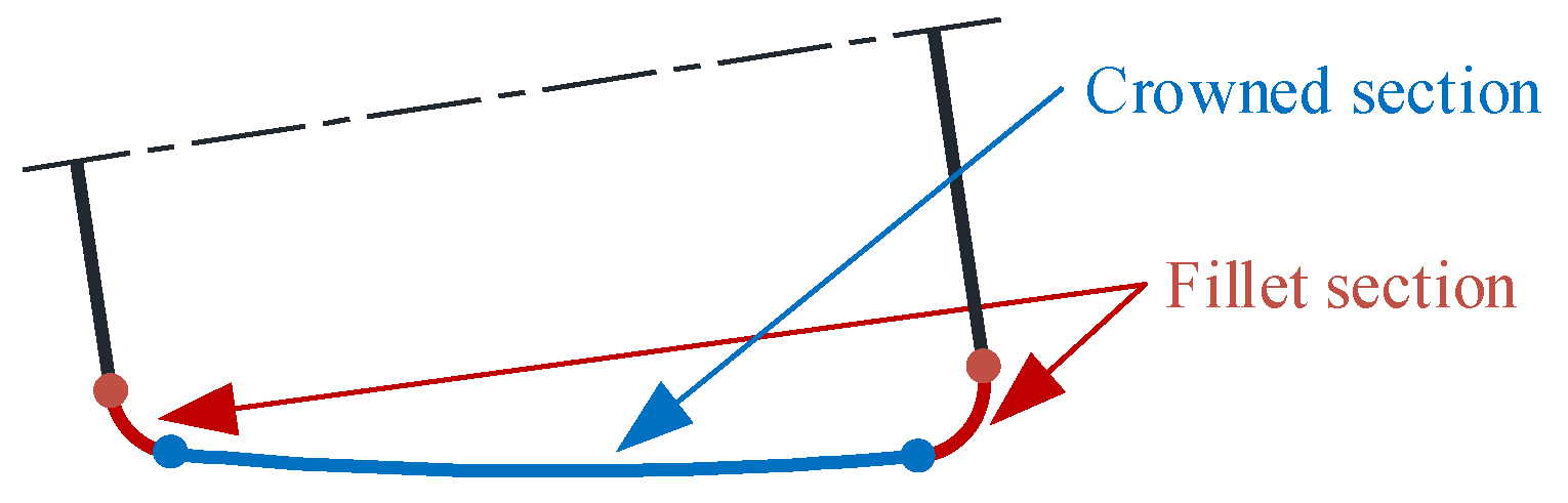
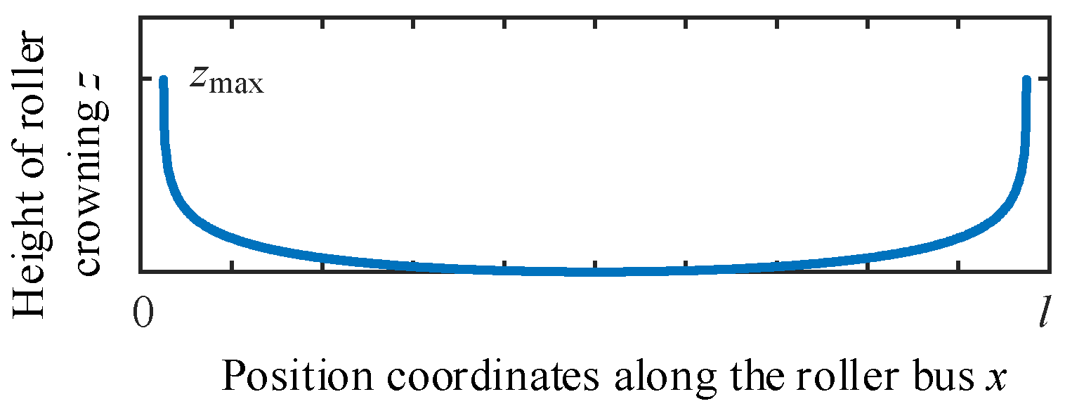
4.1. Logarithmic Crowning of Roller

The roller profile of bearings on the wind turbine spindle needs to be modified to reduce stress concentration and optimize load distribution. There is generally, power function crowning and logarithmic (exponential) crowning of the roller. Logarithmic crowning is not as good as power function crowning under extreme bias load conditions, but the stress distribution of the roller is more uniform under normal conditions [13,17], so the logarithmic crowning method is chosen for the study. The crowning zone of the tapered roller is shown in Figure 12.
In practice, bearing rollers are often subjected to different and changing loads, yet the profile of the rollers in a set of bearing should remain consistent. Therefore, the maximum roller load is taken as the design load in the design of the roller’s crowning.
In the FE model, n nonlinear spring elements are used to replace each roller, and the maximum value after superimposing the n loops spring reaction force is the maximum equivalent roller load Qmax, and the expression is
Q max = F sum i max = j = 1 n F j i max i = 1 , 2 , , Z
where Qmax is the maximum roller load, Fsumi is the ith equivalent roller reaction force after superimposing n loops of spring reaction force, Fji is the ith spring reaction force in loop j, and Z is the number of rollers.
The expression of the crowning function z of the tapered roller is
z = 2 Q π E l w e × ln 1 1 0.3033 2 b l w e 2 x / l w e 2 1
where Q is the roller load, E′ is the equivalent elastic modulus, b is the Hertzian contact half-width, and lwe is the crowning length.
The crowning profile of the roller is shown in Figure 13, where the maximum amount of crowning is denoted as zmax.
For line contact, according to Hertzian contact theory, the contact half-width b is
b = 4 η Q π l ρ 1 / 2
where Σρ is the Curvature sum.
The formula for calculating Σρ is as follows:
ρ = 2 cos β D w + 2 γ i D w ( 1 γ i )
where β is the tapered roller half-cone angle, Dw is the middle diameter of the roller, and γ i = D w cos α i / d m .
Defining f 1 = 2 Q / π E l w e as the load parameter of logarithmic crowning and f 2 = 1 0.3033 × 2 b / l w e as the width parameter of logarithmic crowning, the crowning function changes to
z = f 1 × ln 1 f 2 ( 2 x / l w e ) 2 1
Equation (25) contains two crowning parameters f1 and f2. f1 and f2 are determined by the roller load Q and material parameters, and the roller load Q is the common influence variable. The research of [15] indicated that the effect of the parameter f2 on the stress distribution of the roller is very small, while f1 on the stress distribution of the roller is large. Only f1 needs to be optimized and an adjustment-coefficient cof is added in front of Q in f1 to make it variable, and the expression of the roller crowning function changes to
z = c o f × f 1 × ln 1 f 2 ( 2 x / l w e ) 2 1
The reference values of the crowning parameters f1, f2, b, and z can be derived from theoretical calculations. Using the value of theoretically calculated z as a reference, the amount of crowning z can be adjusted by the adjustment-coefficient cof.

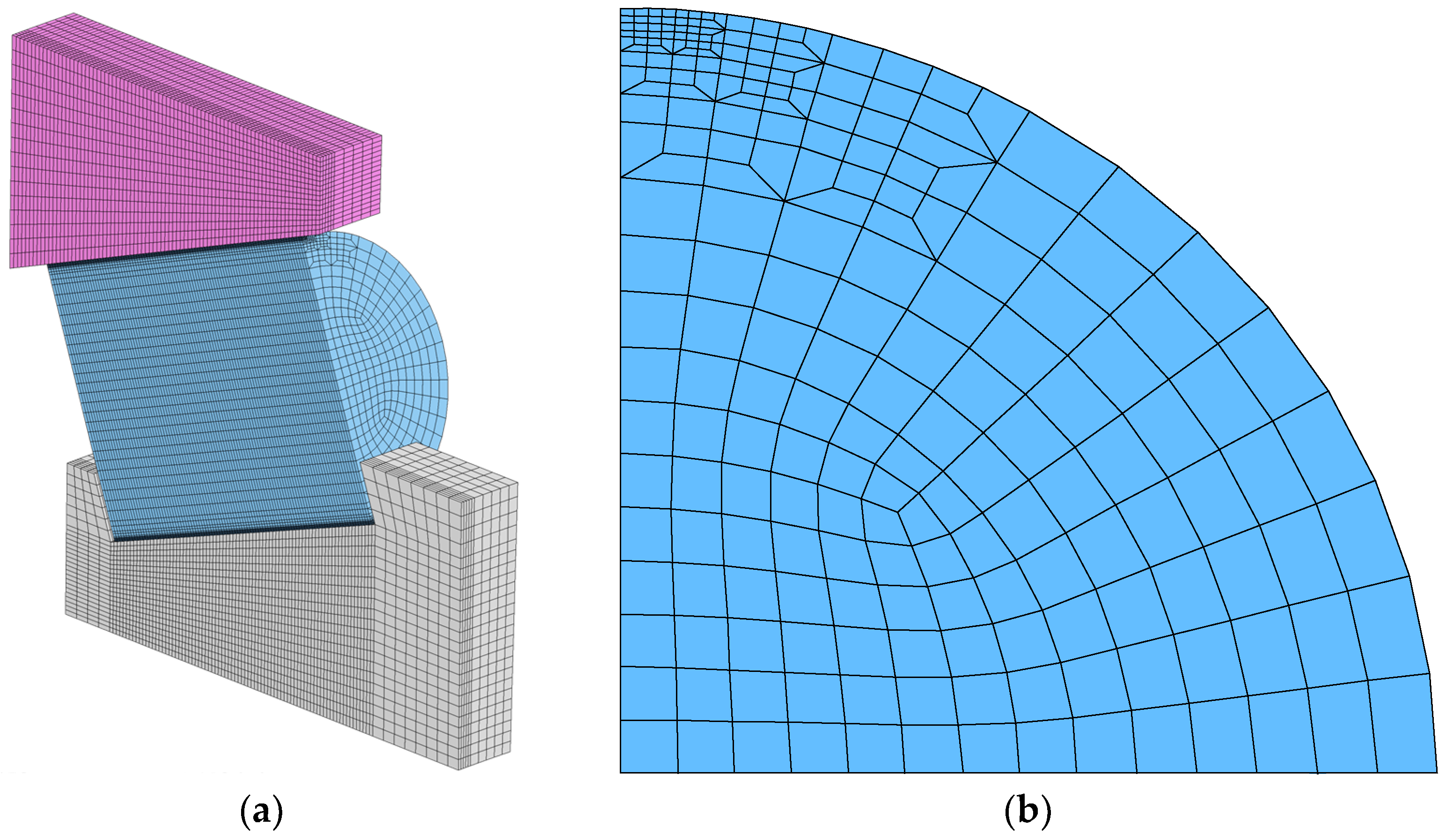
4.2. Mesh of Sub-Model

The profile of bearing roller crowning is an exact function curve and the sub-model needs to have a fine mesh to simulate the contact characteristics of the roller contact area. The mesh of the contact zone of the roller is refined, and the transition mesh is handled finely. The final mesh of the symmetric sub-model is shown in Figure 14, containing a total of 91,364 elements and 99,585 nodes.
For rollers without fillets, especially rollers with a straight profile, stress concentration is generated at the edge of the roller in the analysis with a very high calculated stress value, which neither does match the actual situation [13] nor is conducive to the stress assessment.
After meshing the geometry, the mesh of the roller edge needs to be shrunk in the radial direction by a certain amount, to meet the realistic fillet or chamfer features, the shrunk mesh of the roller edge is shown in Figure 15.

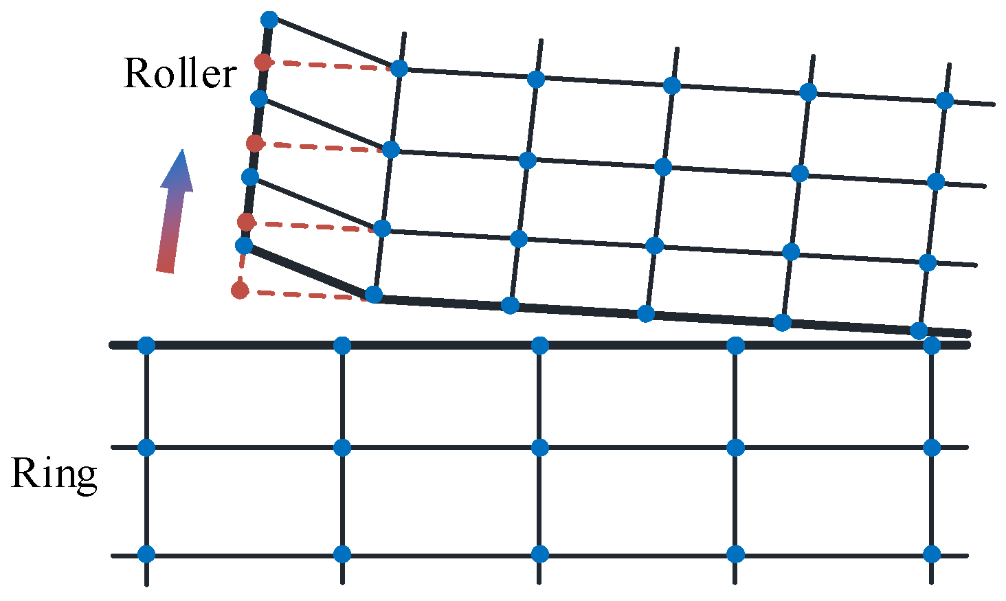
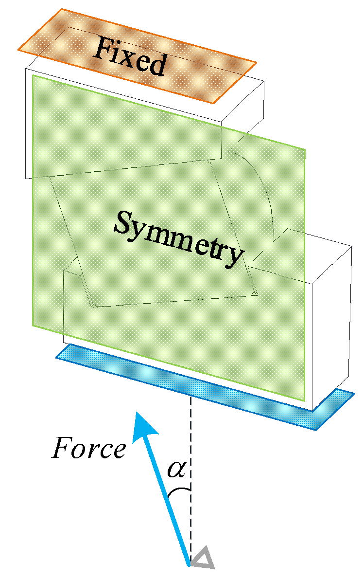
4.3. Boundary Conditions

Superimpose the n loops reaction forces of springs obtained from the FE model of the shaft system. The maximum value of the reaction force after superposition is used as the load boundary of the sub-model. Its direction is approximately the contact normal of the inner raceway. All degrees of freedom of the outer diameter surface of the outer ring of the bearing are fixed. The symmetry boundary is created on the symmetry surface of the rings and roller. Based on the direction of the force boundary vector, a coordinate system is established to constrain the other degrees of freedom of the inner ring bore surface except for the direction of the force. This is shown in Figure 16.
On the symmetry plane, a path is created in the fillet and crowned section on the roller profile on the inner ring side, as shown in Figure 17, to extract the Von Mises stress of the nodes on the path.

5. Analysis and Discussion of Results

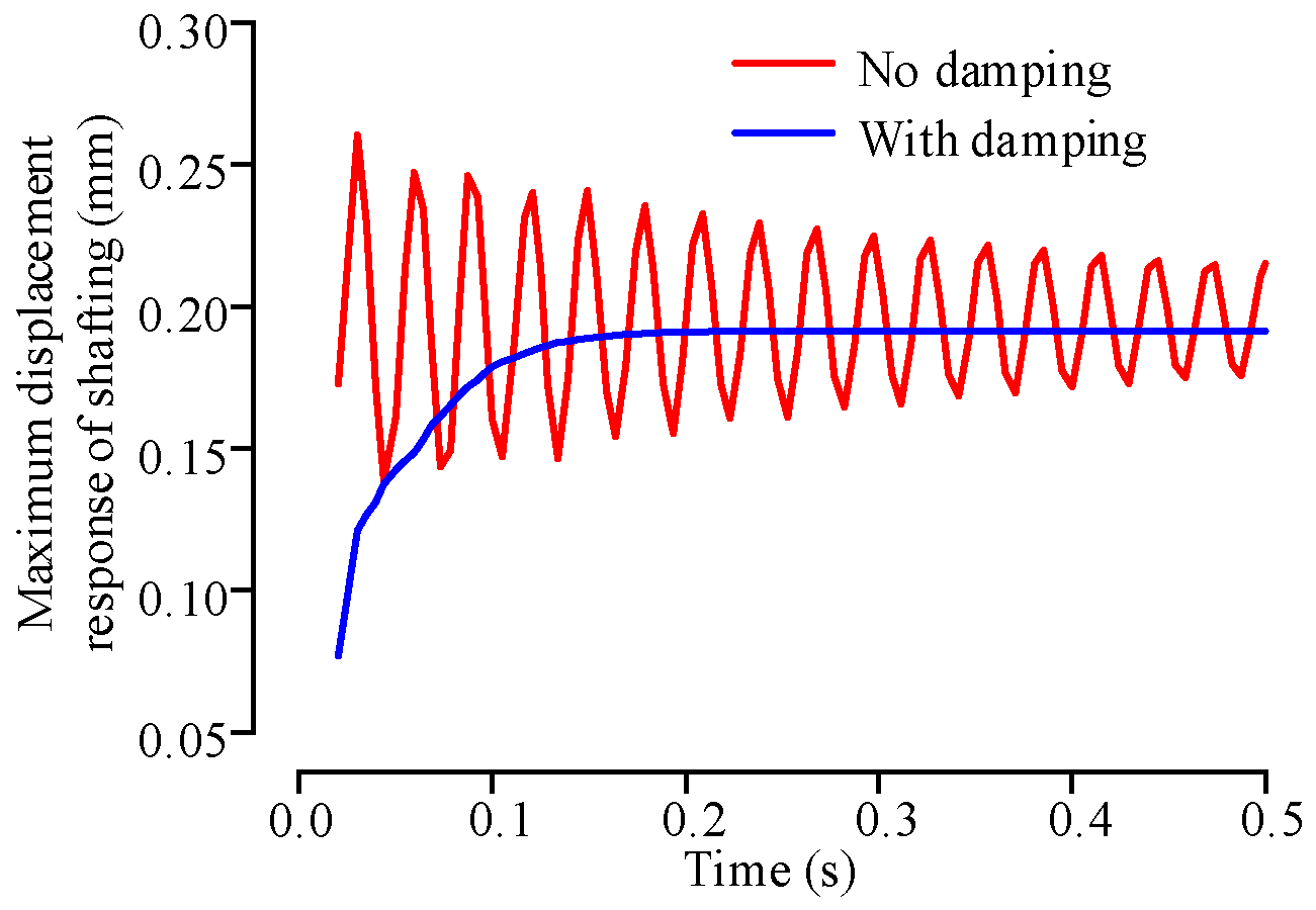
5.1. Effect of Damping on the Solution of the Shaft System

For the 5 spr case, the undamped model and the critically damped model of the FE model of the shaft system are solved, with the maximum displacement of the shaft system as the response index. The comparison of the response of the undamped and damped models is shown in Figure 18. It can be seen that the use of the critical damping technique can solve the FE model of the shaft system quickly and obtain a stable mechanical response.

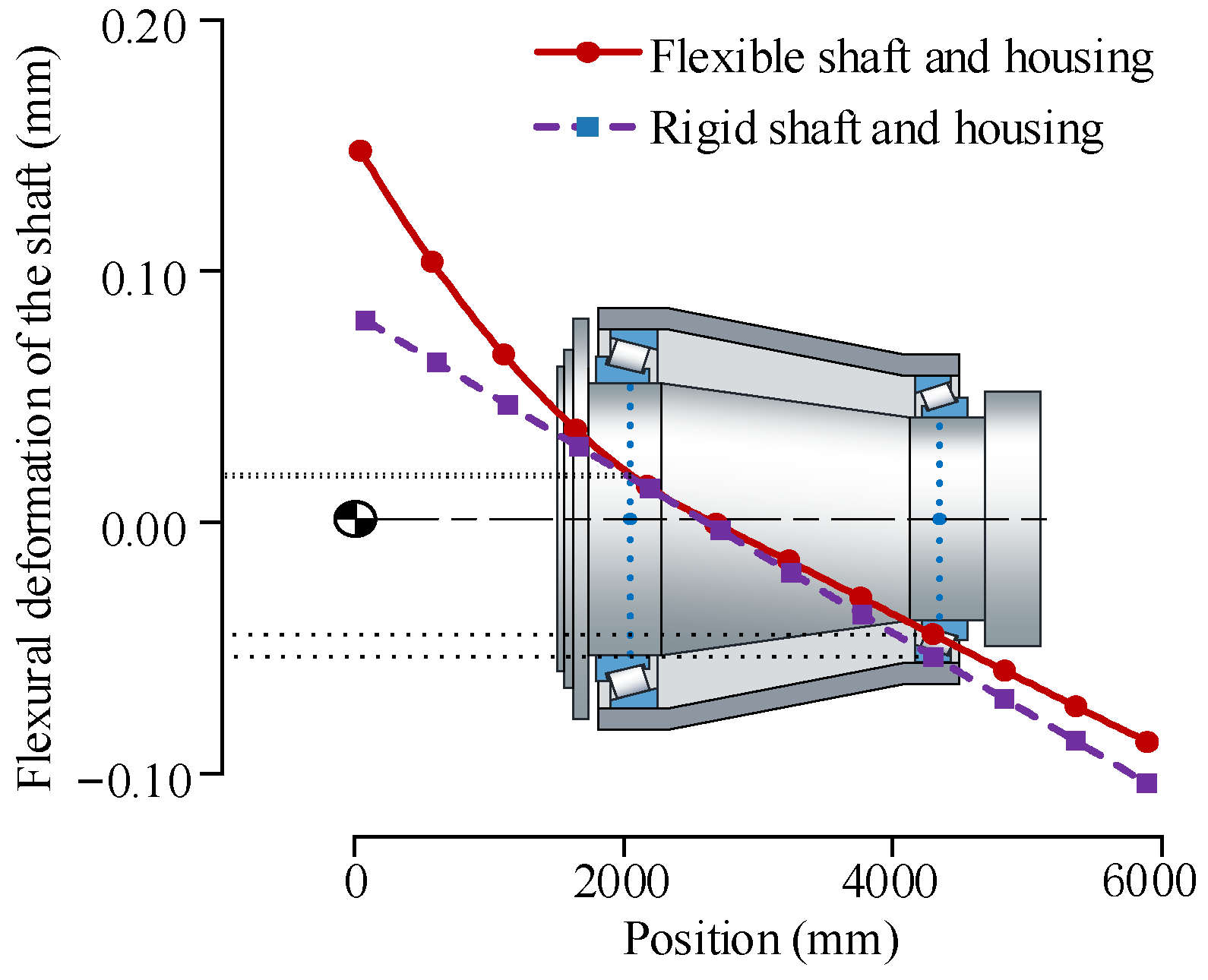
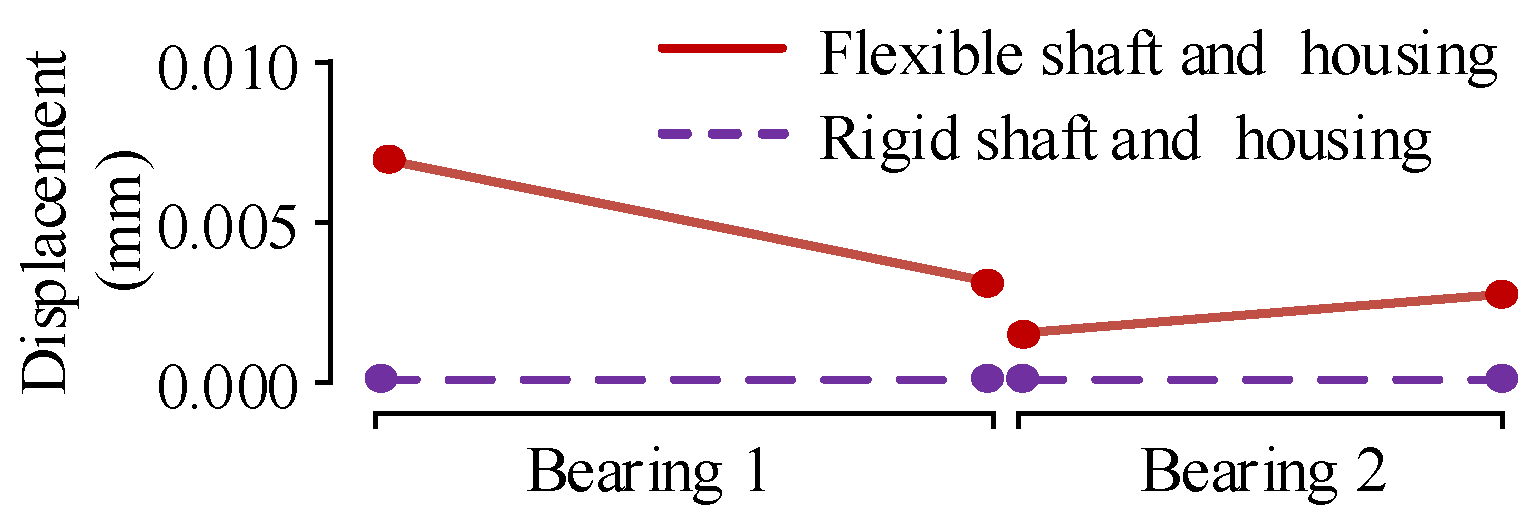
5.2. Influence of Structural Rigidity on the Shaft System

Figure 19 shows the deflection deformation of the shaft under load with a rigid/flexible structure (shaft and bearing housing). Figure 20 gives the relative position change of the profiles of the outer rings of two bearings.
As can be seen in Figure 19, for a model with a rigid shaft and rigid housing, the shaft cannot deform flexibly and can only balance the load by deflecting an angle. In the model with a flexible shaft and a flexible bearing housing, the shaft can be bent and deformed flexibly and the deformation is greatest at the location of the loaded end of the shaft. This is also the location where the deflection is the largest compared to the rigid structure model.
As shown in Figure 20, the flexible housing allows the outer ring of the bearing to have a deflection deformation, which allows the bearing to better balance the load. The outer ring of bearing 1 has the largest deflection. However, combining the above factors, the displacement of the rigid shaft at the center position of bearing 1 has a smaller deviation compared to the flexible shaft, and the displacement of the rigid shaft at the center position of bearing 2 has a larger deviation compared to the flexible shaft. The large displacement of the rigid shaft will cause the load on the bearing to be larger, making the bearing life assessment biased, especially for bearing 2. Therefore, in the actual calculation for the bearing on the shaft system, the coupling effect of the flexibility of the structure on the bearing should be considered.

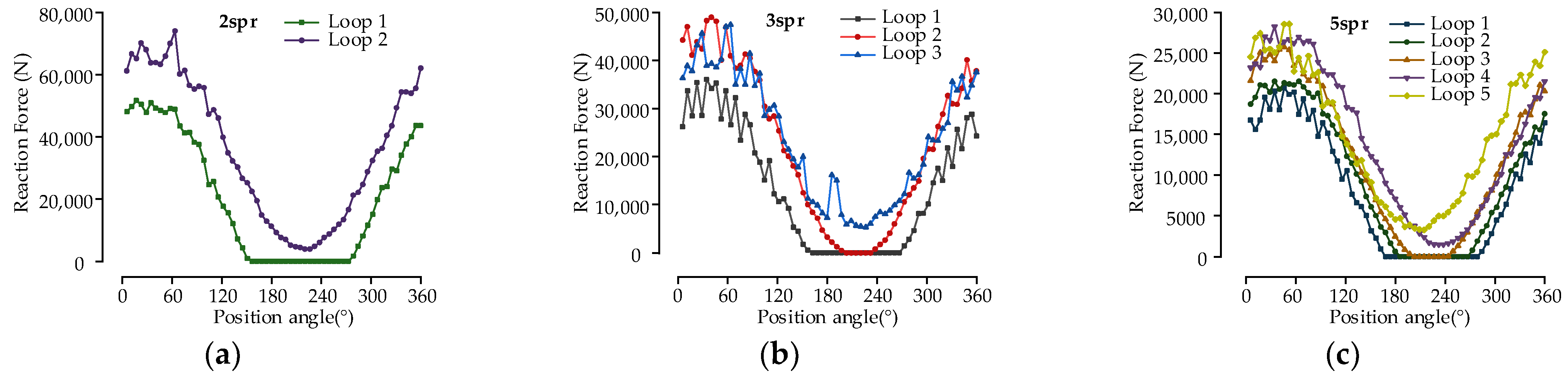
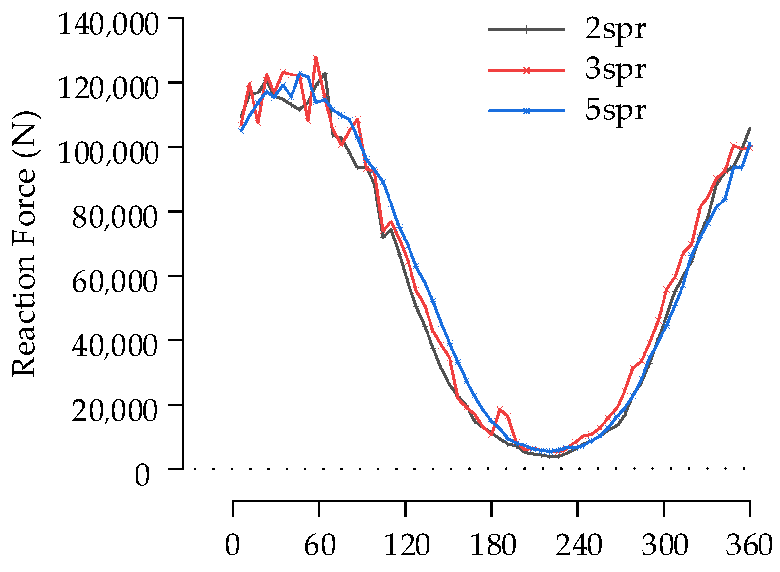
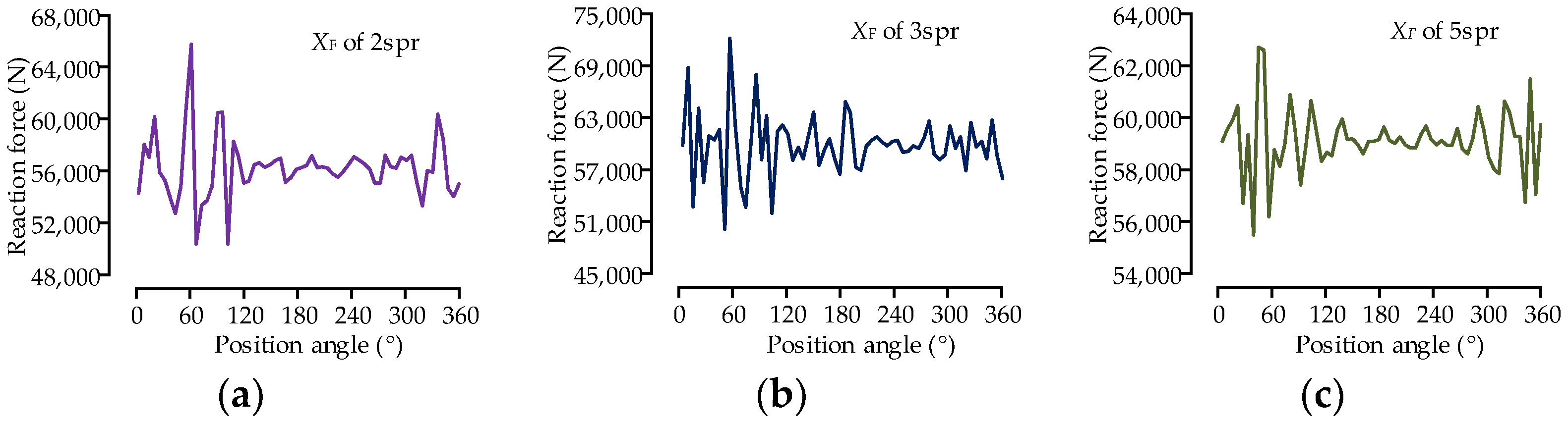
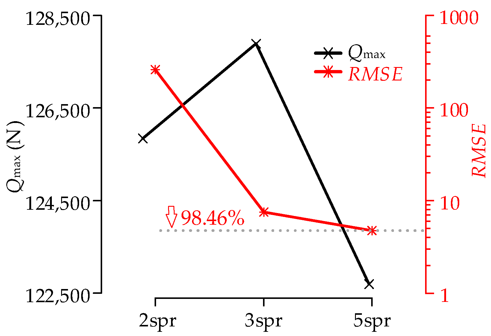
5.3. Effect of the Quantity of Replacement Springs on the Bearing Load Distribution

The n loops reaction forces of the springs for each case are extracted and shown in Figure 21. The equivalent roller load distribution is obtained after superimposing the n loops spring reaction force, and the equivalent roller load distribution under the three cases is shown in Figure 22. All the rollers of bearing 1 under the three cases are under load, and the trend was the same in all three cases, but the fluctuation of the equivalent roller load distribution is different in different cases.
All the rollers of bearing 1 under the three cases are under load, and the trends of the equivalent roller load distribution in the three cases are the same, but the fluctuation of the equivalent roller load distribution is different in different cases. The smaller the data fluctuation, the more uniform the load distribution and the higher the precision. The XF sequences corresponding to the different cases are shown in Figure 23.
As Shown in Figure 24, when the number of replacement springs of a roller is two, three, and five, respectively, the maximum roller load varies irregularly, and the convergence and accuracy of the solution results cannot be evaluated effectively. The RMSE of the equivalent roller load distribution is 259.97, 7.54, and 4.75, respectively. The RMSE shows a significant convergence characteristic. When each roller is replaced by five springs, the RMSE of the equivalent roller load distribution is less than five, which is 98.46% lower than the maximum value of 259.97. At this time, the load distribution is uniform, indicating that the error of the FE model is small and the model has good calculation accuracy. Therefore, the calculation is more accurate when each roller is replaced by five or more springs.
Each roller is replaced by five springs. The FE model considering the flexibility of the structure is solved, and the maximum equivalent roller load is 122,731.03 N. The result of the FE model with a rigid structure is 125,830.48 N. Under the loading conditions in Table 2, the statics solution of the shaft system by ROMAX® 14.5 gives an axial reaction force of Fa = 1.5 × 10⁶ N and a radial reaction force of Fr = 1.9 × 10⁶ N for bearing 1. According to Equation (20), the theoretical result of the maximum roller load is 145,680 N. The FEM result with a rigid structure is 13.63% smaller than the theoretical solution, while the FEM result with a flexible structure is 15.75% smaller than the theoretical solution. The results are compared in Table 3. FEM and numerical theory were used to analyze the bearing capacity of large bearings in the literature [7], and it was pointed out that the numerical results were more conservative than the FEM results, and the FEM load results were generally about 30% smaller than the theoretical solution, with a maximum difference of 98.9%. In the research of [26], it is also pointed out that the theoretical result of the bearing load based on the flexible ring assumption is less than the results based on the rigid ring assumption. The results of the FE model with flexible structure in this paper are smaller than the theoretical solution, and the deviation is within 20%, so the FE model proposed in this paper is reasonable.
From Figure 22 and Table 3, it can be seen that all rollers of bearing 1 in the shaft system are loaded, which is the same as the actual. The maximum equivalent roller loads of the FE model with the flexible structure and the FE model with the rigid structure are lower than the theoretical results to some extent. The results of the FE model with a flexible structure are the smallest and within a reasonable range. This is because the FE model takes into account the flexibility of the structure, which optimized the load distribution of the bearing. The maximum roller load calculated is reduced and is more in line with reality. Compared with the FE model with a rigid structure, the FE model considering the flexibility of structure can better balance the load and calculate the load distribution more accurately.

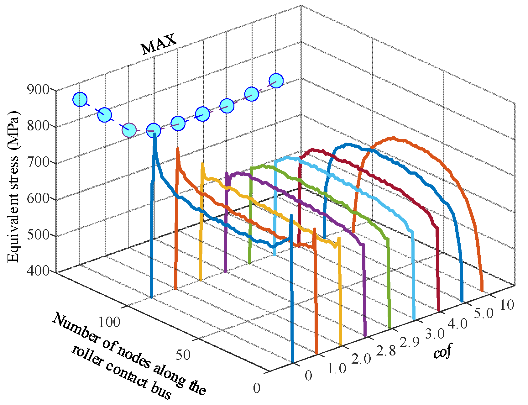
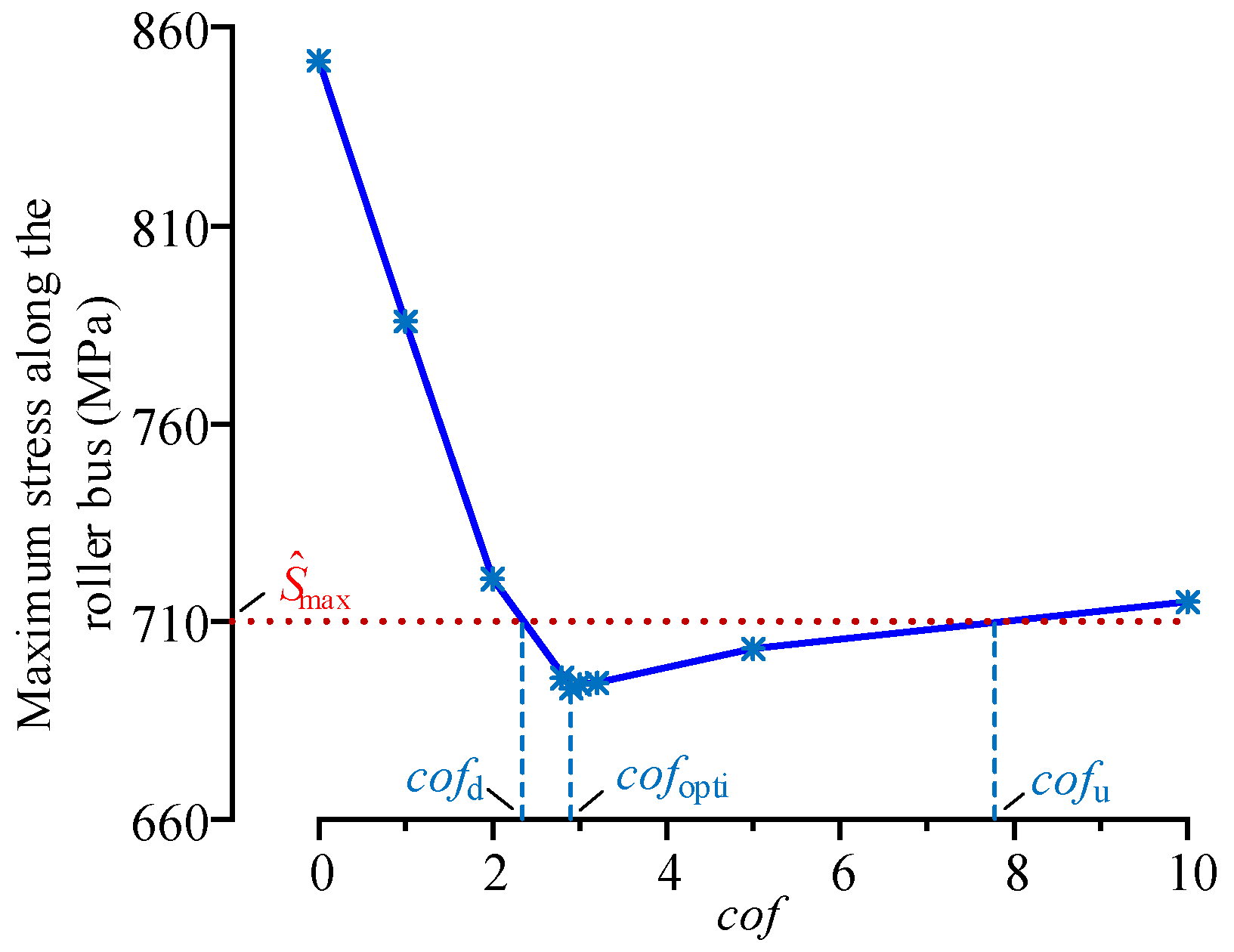
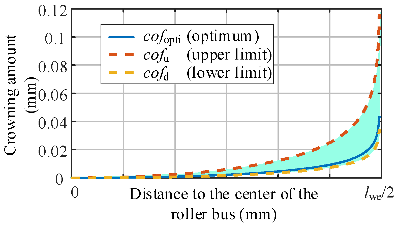
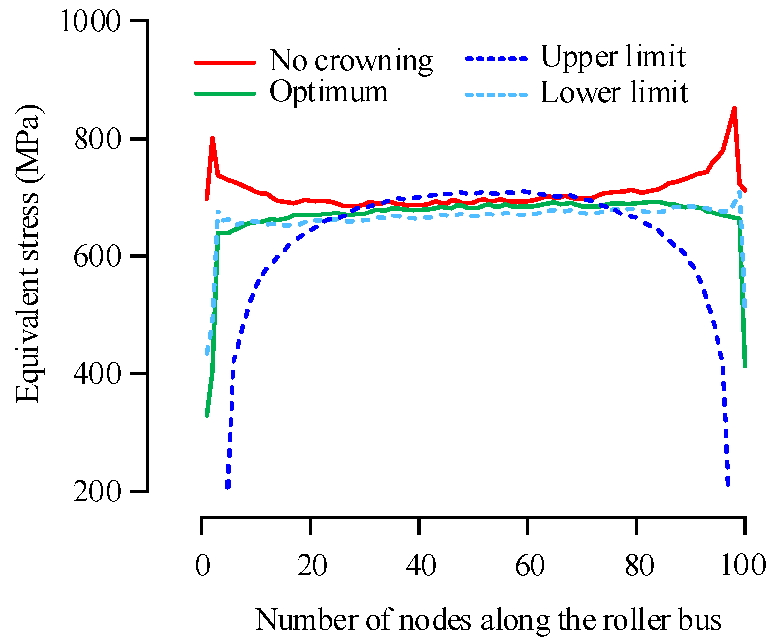
5.4. Design of Optimum Crowning and Its Tolerance of the Roller

The maximum value of the superimposed spring reaction force of five loops is used as the boundary of the bearing sub-model, and the Von Mises stress distribution of the nodes along the profile at the inner ring side of the roller when the logarithmic crowning parameter cof takes different values are shown in Figure 25.
This can be seen in Figure 25. When the roller is not crowned, there is obvious stress concentration at both ends of the roller, and a slight sawtooth-like fluctuation of stress in the middle of the roller, which is caused by the FE mesh error. With the increase of crowning parameter cof of the roller, the stress concentration at the roller edge is effectively relieved or eliminated, and the maximum stress along the roller profile is obviously reduced. With the further increase of crowning parameter cof, the stress concentration appears in the middle of the roller, and the maximum stress along the roller profile rebounds slowly.
The effect of the crowning parameter cof on the maximum stress along the roller profile is shown in Figure 26.
From Figure 26, it is clear that the maximum stress of the roller profile is a function of the logarithmical crowning parameter cof. With the increase of cof, there exists a unique value cofopti which makes the maximum stress of the roller profile minimum. To meet the engineering application, the cof boundary values can be obtained when given the upper limit of the range of the maximum stress S ^ max , which are noted as cofd and cofu, and the tolerance range of the crowning parameters is [cofd, cofu].
The value of Ŝmax affects the tolerance range of the profile of the bearing roller. Too large Ŝmax will lead to large roller contact stress, and too small Ŝmax will lead to a narrow tolerance band, which is not conducive to practical application. Note that the range of maximum contact stress of the bearing roller in Figure 26 is RS. The variation range of the maximum equivalent stress is set as 0.1 RS, that is, the S ^ max is set as 710 MPa, and the tolerance range [cofd, cofu] of the modification parameters is [2.3, 7.8].
The crowning profile of the roller and its tolerance zone corresponds to the optimum crowning parameter cof for bearing 1 as shown in Figure 27.
The stress distribution along the profile of the maximum loaded roller before and after being crowned is shown in Figure 28.
When cof is equal to 0, i.e., when the roller is not crowned, the stress distribution along the roller profile appears as obvious edge stress concentration, and the maximum stress of the roller profile is 851.52 MPa. When cof is equal to cofopti, that is when the roller is optimally crowned, the stress distribution along the roller profile is uniform without obvious stress concentration, the maximum stress is 693.07 MPa, and the maximum stress of the roller profile is reduced by 18.6% compared with the uncrowned. When cof is equal to cofd or cofu, the maximum stress of the roller profile is 710 MPa, and the maximum stress of the roller profile of the roller is reduced by 16.6% compared with the uncrowned.

6. Conclusions

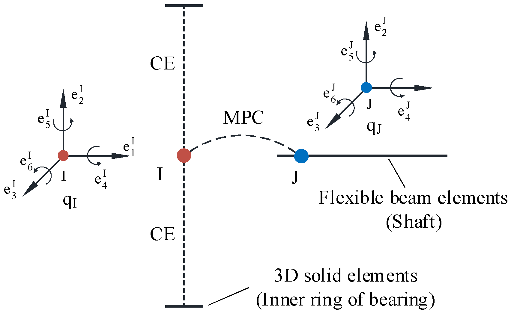
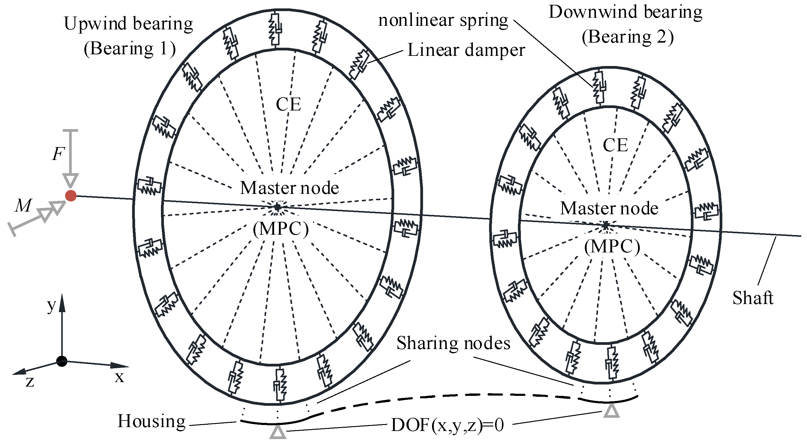
  • CE and MPC algorithms were used to connect the shaft and bearing, and nonlinear spring elements and dampers with critical damping were used to replace the rollers to construct the FE model of the shaft assembly. The model has good convergence.
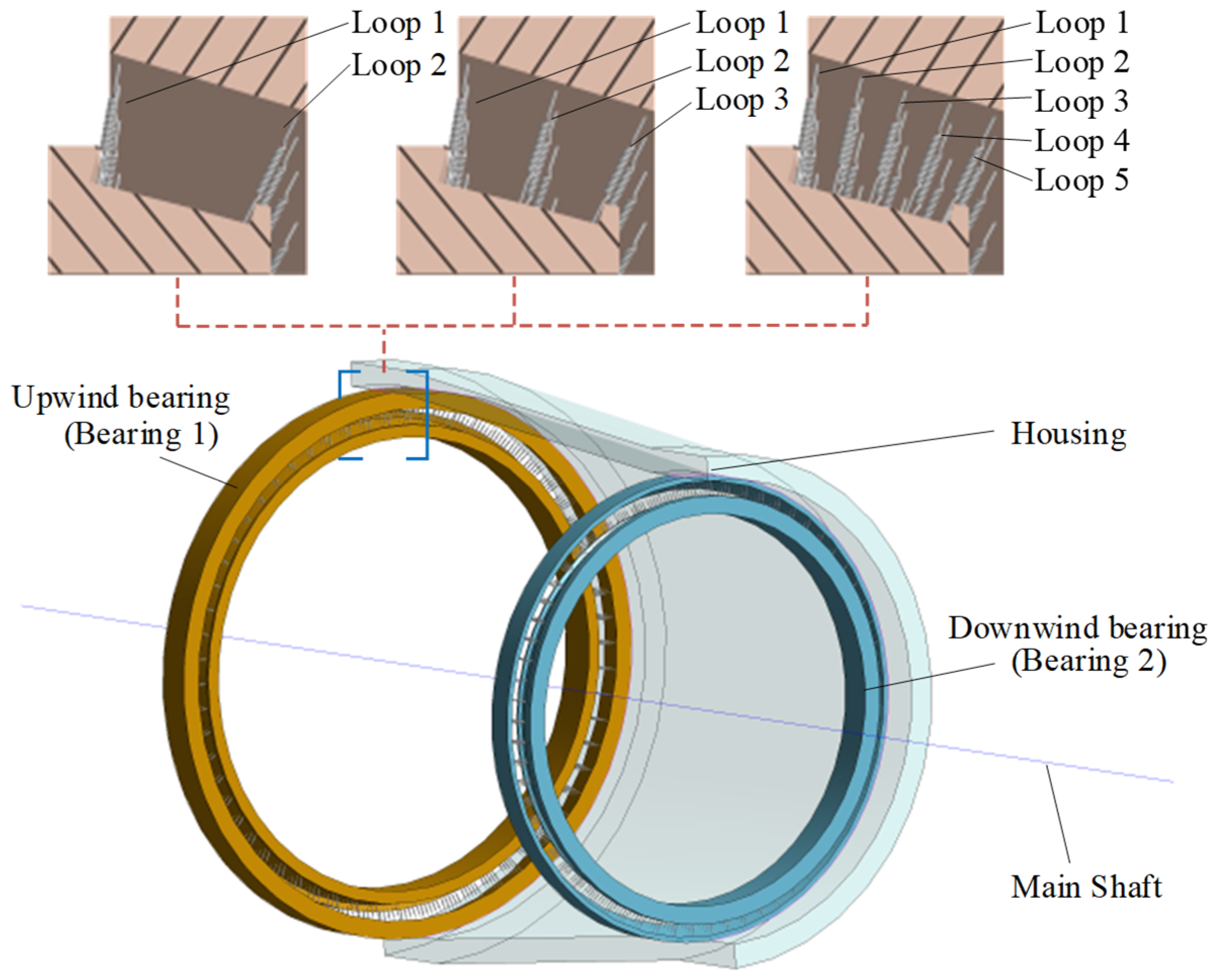
  • The high-pass filter based on FFT was used to filter the sequences of spring load distribution and then performed convergence analysis using RMSE, which can obtain the ideal number of replacement springs for each roller.
  • By analyzing the deformation of the shaft and the relative position of the outer profiles of the outer rings of two bearings, the FE model of the shaft system considering the structure’s flexibility has higher calculation accuracy than the FE model with a rigid structure. The maximum roller load of the FE model with a flexible structure is 15.75% less than the theoretical solution, which is within a reasonable range.
  • The sub-model of the upwind bearing is constructed with structured mesh. With the crowning parameters of the logarithmically crowned roller as the design variables and the maximum Von Mises stress of the roller profile at the center of the contact area as the design target, the optimal logarithmic crowning of the roller and its tolerance zone under the given working conditions are obtained.
The FE model considering the flexibility of the support structure of the shaft system can obtain a more accurate load distribution of bearing, and can accurately design the bearing profile based on actual working conditions. The FE modeling method proposed can be further used to construct the calculation and analysis system of the shaft assembly of a large wind turbine and to provide support for the precision design of bearings in large shaft systems.

Author Contributions

Conceptualization, R.N. and X.L.; methodology, R.N.; software, X.L.; validation, S.Z., Y.C. and Z.Z.; formal analysis, X.L.; investigation, X.L.; resources, B.W.; data curation, X.L.; writing—original draft preparation, X.L.; writing—review and editing, R.N.; visualization, X.L.; supervision, R.N.; project administration, R.N.; funding acquisition, R.N. All authors have read and agreed to the published version of the manuscript.

Funding

This research was funded by the National Natural Science Foundation of China, grant number 52005158, and the Key Research and Development Project of Shandong Province, grant number 2020CXGC011003.

Data Availability Statement

Not applicable.

Conflicts of Interest

The authors declare that they have no conflict of interest.

References

  1. Doll, M.N.K.; Gary, L. Tribological advancements for reliable wind turbine performance. Philos. Trans. 2010, 368, 4829–4850. [Google Scholar]
  2. Hart, E.; Clarke, B.; Nicholas, G.; Amiri, A.K.; Stirling, J.; Carroll, J.; Dwyer-Joyce, R.; McDonald, A.; Long, H. A review of wind turbine main bearings: Design, operation, modelling, damage mechanisms and fault detection. Wind. Energy Sci. 2020, 5, 105–124. [Google Scholar] [CrossRef] [Green Version]
  3. Smolnicki, T.; Rusiński, E. Superelement-based modeling of load distribution in large-size slewing bearings. J. Mech. Des. 2007, 129, 459–463. [Google Scholar] [CrossRef]
  4. Chen, G.; Wang, C.; Xiao, Z. Effects of supporting structure and bolt connection on the fatigue life and carrying capacity of a slewing bearing. J. Eng. Tribol. 2016, 231, 766–782. [Google Scholar] [CrossRef]
  5. Chen, G.; Wen, J. Load Performance of Large-Scale Rolling Bearings With Supporting Structure in Wind Turbines. J. Tribol. 2012, 134, 041105. [Google Scholar] [CrossRef]
  6. Plaza, J.; Abasolo, M.; Coria, I.; Aguirrebeitia, J.; Igor, F.B. A new finite element approach for the analysis of slewing bearings in wind turbine generators using superelement techniques. Meccanica 2015, 50, 1623–1633. [Google Scholar] [CrossRef]
  7. Li, Y.; Jiang, D.; Song, L. Finite Element Analysis of Pitch Bearing in Wind Turbine Considering Influence of Installation Structures. Acta Energ. Sol. Sin. 2019, 40, 2021–2027. (In Chinese) [Google Scholar]
  8. Aguirrebeitia, J.; Abasolo, M.; Avilés, R.; Igor, F.B. General static load-carrying capacity for the design and selection of four contact point slewing bearings: Finite element calculations and theoretical model validation. Finite Elem. Anal. Des. 2012, 55, 23–30. [Google Scholar] [CrossRef]
  9. He, P.; Liu, R.; Hong, R.; Wang, H.; Yang, G.; Lu, C. Hardened raceway calculation analysis of a three-row roller slewing bearing. Int. J. Mech. Sci. 2018, 137, 133–144. [Google Scholar] [CrossRef]
  10. Śpiewak, S. Methodology for calculating the complete static carrying capacity of twin slewing bearing. Mech. Mach. 2016, 101, 181–194. [Google Scholar] [CrossRef]
  11. Martín, I.; Aguirrebeitia, J.; Heras, I.; Abasolo, M. Efficient Finite Element modelling of crossed roller wire race slewing bearings. Tribol. Int. 2021, 161, 107098. [Google Scholar] [CrossRef]
  12. Kania, L.; Pytlarz, R.; Śpiewak, S. Modification of the raceway profile of a single-row ball slewing bearing. Mech. Mach. Theory 2018, 128, 1–15. [Google Scholar] [CrossRef]
  13. Ju, S.H.; Horng, T.L.; Cha, K.C. Comparisons of contact pressures of crowned rollers. J. Eng. Tribol. 2000, 214, 147–156. [Google Scholar] [CrossRef]
  14. Fujiwara, H. Logarithmic profile of rollers in roller bearing and optimization of the profile. Trans. Jpn. Soc. Mech. Eng. 2006, 72, 338–345. (In Japanese) [Google Scholar] [CrossRef] [Green Version]
  15. He, Z.; Shao, M.; Ye, G. Optimum Design Method for Logarithmic Crowned Tapered Rollers. Mech. Eng. Technol. 2016, 5, 38–46. [Google Scholar] [CrossRef]
  16. Li, Y.; Gao, Y. Internal load distribution of single-row tapered roller bearings doubly supporting main shaft of wind turbine. Adv. Mech. Eng. 2022, 14, 16878132221098895. [Google Scholar] [CrossRef]
  17. Zhang, T.; Yang, X.; He, L.; Bu, Z.J.; Nie, W.; Li, M. Research on the Design Method of Roller Modification Curve for Wind Turbine. J. Mech. Strength 2021, 43, 183–190. (In Chinese) [Google Scholar]
  18. Li, Y.; Xu, Z.; Liu, Q.; Wang, H. Analysis on Contact Behavior for Extra Large Size Tapered Roller Bearings in Wind Turbines Based on PERMAS. Bearing 2014, 5, 1–4. (In Chinese) [Google Scholar]
  19. Liu, J.; Dong, H.; Wang, H.; Wang, Y.Y. Finite Element Analysis of Slewing Bearing Based on Rolling Element Solid Model and Substructure Technology. Bearing 2018, 12, 9–13. (In Chinese) [Google Scholar]
  20. Kania, L. Modelling of rollers in slewing bearing calculations with the use of finite elements. Mech. Mach. Theory 2006, 41, 1359–1376. [Google Scholar] [CrossRef]
  21. Harris, T.A.; Kotzalas, M.N. Advanced Concepts of Bearing Technology: Rolling Bearing Analysis, 5th ed.; CRC Press: Boca Raton, FL, USA, 2006; pp. 3–7. [Google Scholar]
  22. Palmgren, A. Ball and Roller Bearing Engineering, 3rd ed.; SKF Industries Inc.: Philadelphia, PA, USA, 1959. [Google Scholar]
  23. Wang, P.; Wang, Q.; Xu, X.; Chen, N. Fractional Critical Damping Theory and Its Application in Active Suspension Control. Shock. Vib. 2017, 2017, 2738976. [Google Scholar] [CrossRef]
  24. Zeng, P.; Lei, L.; Fang, G. Finite Element Analysis Guide: Modeling and Analysis of Structure; China Machine Press: Beijing, China, 2011; pp. 428–430. [Google Scholar]
  25. Lundberg, G.; Palmgren, A. Dynamics capacity of rolling bearings. Acta Polytech. 1947, 1, 7. [Google Scholar] [CrossRef]
  26. Zhang, H.; Chen, S.; Dou, Y.; Fan, H.; Wang, Y. Mechanical model and contact properties of double row slewing ball bearing for wind turbine. Rev. Adv. Mater. Sci. 2021, 60, 112–126. [Google Scholar] [CrossRef]
Figure 1. Design of logarithmic crowned roller for wind turbine spindle bearing.
Machines 11 00028 g001
Figure 2. Structure and load of wind turbine spindle. (a) Load direction coordinate system; (b) Structure and load.
Machines 11 00028 g002
Figure 3. Replace rollers with nonlinear spring elements.
Machines 11 00028 g003
Figure 4. Stress-strain characteristics of the nonlinear spring element.
Machines 11 00028 g004
Figure 5. Replace rollers with nonlinear springs and dampers. (a) Replace rollers with springs; (b) Replace rollers with springs and dampers.
Machines 11 00028 g005
Figure 6. Shaft-bearing coupling diagram.
Machines 11 00028 g006
Figure 7. Coupling connection relationship of the shaft assembly.
Machines 11 00028 g007
Figure 8. FE model of shaft system with different quantities of replacement springs.
Machines 11 00028 g008
Figure 9. The positions and forces of the tapered rollers. (a) The angular positions of the rollers; (b) Forces of tapered rollers.
Machines 11 00028 g009
Figure 10. Tapered roller forces and bearing forces.
Machines 11 00028 g010
Figure 11. Spatial relationship between roller force and bearing forces.
Machines 11 00028 g011
Figure 12. Crowned section and fillet section of tapered roller.
Machines 11 00028 g012
Figure 13. Logarithmic crowning profile of roller.
Machines 11 00028 g013
Figure 14. Mesh of the symmetric sub-model. (a) The mesh of sub-model; (b) The mesh of roller cross-section.
Machines 11 00028 g014
Figure 15. Radial shrinkage of mesh at roller edge.
Machines 11 00028 g015
Figure 16. Boundary conditions of the sub-model.
Machines 11 00028 g016
Figure 17. Path defined in post-processing.
Machines 11 00028 g017
Figure 18. Mechanical response of FE model of the shaft system.
Machines 11 00028 g018
Figure 19. Comparison of shaft deformation under rigid and flexible structure.
Machines 11 00028 g019
Figure 20. Relative position of the outer profiles of the outer rings of two bearings.
Machines 11 00028 g020
Figure 21. Spring reaction force in different cases. (a) Spring reaction force of 2 spr; (b) Spring reaction force of 3 spr; (c) Spring reaction force of 5 spr.
Machines 11 00028 g021
Figure 22. Equivalent roller load distribution of bearing 1 under different cases.
Machines 11 00028 g022
Figure 23. XF sequences in different cases. (a) XF sequences of 2 spr; (b) XF sequences of 3 spr; (c) XF sequences of 5 spr.
Machines 11 00028 g023
Figure 24. Maximum roller load vs. RMSE of maximum equivalent roller load.
Machines 11 00028 g024
Figure 25. Stress distribution along the roller profile at different crowning parameter cof.
Machines 11 00028 g025
Figure 26. Maximum stress of the roller profile at different crowning parameter cof.
Machines 11 00028 g026
Figure 27. Optimal crowning profile and its tolerance zone of roller of bearing 1.
Machines 11 00028 g027
Figure 28. Stress distribution along the roller profile before and after being crowned.
Machines 11 00028 g028
Table 1. Geometrical parameters of bearings.
ParameterValue
Bearing 1Bearing 2
Inner diameter d (mm)18501600
Number of rollers Z6265
The contact angle of inner raceway αi (°)15.5819.5
The contact angle of outer raceway αe (°)17.121.17
The contact angle of roller end–ring flange αf (°)83.5269.67
Length of rollers l (mm)12198
Roller diameter in the middle Dw (mm)95.08573.26
Roller half taper angle β (°)0.750.833
pitch diameter dm (mm)20431750
Table 2. Load parameters of the shaft system.
Fx/NFy/NFz/NMy/NmMz/Nm
7.5 × 1051.1 × 1063 × 1041700−2700
Table 3. Maximum roller load of FEM and theoretical results.
FEM with Flexible Structure/NFEM with Rigid Structure/NTheory Based on Rigid Ring Assumption/N
122,731.03125,830.48145,680
(−15.75%)(−13.63%)(—)
Disclaimer/Publisher’s Note: The statements, opinions and data contained in all publications are solely those of the individual author(s) and contributor(s) and not of MDPI and/or the editor(s). MDPI and/or the editor(s) disclaim responsibility for any injury to people or property resulting from any ideas, methods, instructions or products referred to in the content.

