Article

Multiobjective Design Optimization of Lightweight Gears

1
Department of Mechanical, Energy and Management Engineering, University of Calabria, DIMEG, cubo 45C, 87036 Rende, Italy
2
Siemens Industry Software NV, Interleuvenlaan 68, B-3001 Leuven, Belgium
*
Author to whom correspondence should be addressed.
Machines 2022, 10(9), 779; https://doi.org/10.3390/machines10090779
Submission received: 1 August 2022 / Revised: 30 August 2022 / Accepted: 5 September 2022 / Published: 7 September 2022
(This article belongs to the Special Issue Advances of Machine Design in Italy 2022)

Abstract

:
Lightweight gears have the potential to substantially contribute to the green economy demands. However, gear lightweighting is a challenging problem where various factors, such as the definition of the optimization problem and the parameterization of the design space, must be handled to achieve design targets and meet performance criteria. Recent advances in FE-based contact analysis have demonstrated that using hybrid FE–analytical gear contact models can offer a good compromise between computational costs and predictive accuracy. This paper exploits these enabling methodologies in a fully automated process, efficiently and reliably achieving an optimal lightweight gear design. The proposed methodology is demonstrated by prototyping a software architecture that combines commercial solutions and ad hoc procedures. The feasibility and validity of the proposed methodology are assessed, considering the multiobjective optimization of a transmission consisting of a pair of helical gears.

1. Introduction

Gears are crucial components for a wide range of applications: from recreational equipment to transportation, and from energy production (aka wind turbine gearboxes) to industrial machinery. Gear design has been perfected over millennia, as it encompasses a fundamental theory that enables efficient mechanical power transmission. Nevertheless, some margin of technological improvement can still be pursued. Gears design could be refined even further by exploiting the more recent advances in material science and modern designs, and manufacturing processes.
Over the last few decades, mass reduction was pursued as one of the main drivers of performance enhancement in the aerospace sector, from which lightweight design methodologies originated. Later, the usage of lightweight designs, including lightweight gears, expanded to the automotive sector, playing a crucial role in satisfying increasingly stricter regulations on combustion engine emission and fuel efficiency. The recent literature shows that weight reduction greatly benefits system efficiency in vehicles [1] and aircraft. In the latter, gearboxes can account for up to 15% [2] of the total mass saving, significantly lowering fuel consumption [3].
The improving computational performance of modern computers is opening new horizons concerning the adoption of physics-inspired models in optimization routines. In this context, model-based optimization strategies employ high-fidelity models to capture the relevant physics and obtain the proper model parameterization, which allows for netting a direct link between design parameters and model variables. As a result, the more expensive optimization processes based on prototypes and physical testing can be substituted by reliable model-based processes.
More specifically, the design of lightweight gears relies on the possibility of effectively modeling their dynamic behavior in the context of lumped or detailed system-level simulations. State-of-the-art solutions to decrease gear mass rely either on a geometrical approach where the material is removed from the gear blank [4,5] or on a multimaterial approach that combines lightweight materials with high-performance steel [6]. The geometrical approach typically exploits thin-rim geometries and the subtraction of features (e.g., holes or slots) from the gear body. In this regard, attention must be paid to prevent the deterioration of noise and vibration (N and V) performance [4] and even the impairment of the structural integrity of the geared transmission. Nonetheless, the analysis-driven design of lightweight gears requires advanced simulation methods to properly consider the body geometry and its impact on the gear flexibility [5]. The multimaterial approach exploits material-level properties to improve component performance, and has demonstrated potential for N and V improvement in lightweight gears [6]. However, several technological gaps must still be covered before achieving a maturity level that enables its industrial applicability.
Recent trends suggest that transmission lightweighting may pave the way to system-level performance improvement. The goal of concurrently reducing the gears’ weight and the vibrations in transmission was pursued by Yang et al. in [7], and by Ramadani et al. in [8]. In [9], the effects of lightweight gear blank on static and dynamic behavior for electric-drive systems in electric vehicles were studied using a hybrid finite-element–analytical method in conjunction with a rigid–flexible coupled dynamic model that took into account the flexibility of the shaft, bearings, and housing.
Recent advances in FE-based contact analysis demonstrated that hybrid FE–analytical gear contact models [10,11,12] could better compromise computational costs and predictive accuracy. Their usage enables optimally tuning all relevant lightweighting parameters without sacrificing dynamic performance.
Built on the experience that matured in [10], this paper proposes a complete workflow required for accomplishing a multiobjective design space exploration of lightweight transmissions. We exploit the geometrical approach to derive a lightweight helical gear design. The joint objectives of optimizing the weight, and N and V performance of geared transmissions are pursued by exploiting a hybrid FE–analytical gear contact model in conjunction with multiobjective design optimization software resulting in a fully automatized optimization toolchain. Moreover, the obtained framework could easily be expanded to further generalize the optimization problem by including more complex features or using different materials.
The remainder of the paper is structured as follows: an overview of the proposed multiobjective optimization strategy is illustrated in Section 2, while Section 3 describes the hybrid FE–analytical method employed to analyze the gears meshing. In Section 4, the basic steps of the optimization workflow are illustrated. Section 5 describes an optimization case where a pair of helical gears, one of which with a lightweight design, was optimized, and presents the obtained results. Section 6 closes the paper by discussing the achieved results and proposing further advances.

2. Multiobjective Optimization Strategy

The optimal design of lightweight gears can be formulated as a multiobjective optimization problem (MOP). Such a problem involves the joint minimization of multiple, usually conflicting, objective functions while varying a set of decision variables. Mathematically, a MOP is described as:
min x   F x ,   s u b j e c t   t o   x   X n
which describes the joint minimization of all the components of objective function F :   F x = f 1 x ,   f 2 x ,     ,   f n x , as a function of decision vector x . The effect of enforcing any constraint results in a reduction in the feasible decision space, X . The image of feasible decision set X is defined as feasible objective space Z:
Z = F x ,   x X
Optimal solutions to the MOP usually comprise a subset of feasible solutions that are not dominated by any other feasible alternative. Geometrically, they are confined at the edges of the feasible objective space, constituting the well-known Pareto front. The inverse image of the Pareto front is called the Pareto optimal set. As depicted in Figure 1, such a representation offers valuable insight to designers, as it allows for them to immediately distinguish the optimal solutions and select the more suitable one depending on the considered criterion for prioritizing between the different objectives.
In engineering optimization, the goodness of an algorithm is measured by looking at two metrics: efficiency and robustness. Efficiency refers to the ability of an algorithm to achieve the optimal solution within a prescribed confidence interval with a minimal number of iterations. Robustness instead concerns the ability of the algorithm to achieve the same objective with a similar number of iterations, irrespective of the starting design. In this contribution, both efficiency and robustness were attempted thanks to the usage of the Siemens Simcenter software ecosystem (Release 2020.2, Siemens PLM, Leuven, Belgium). In particular, we relied on the Siemens Simcenter HEEDS|MDO package [13] (Release 2020.2.1, Siemens PLM, Leuven, Belgium), considered for its design space exploration and optimization capabilities, in conjunction with Siemens Simcenter 3D, which is a fully integrated CAE solution, of which we used two modules: the Simcenter 3D Transmission Builder [14] and the Simcenter 3D Motion solver [15], enabling an efficient simulation of multibody models.

HEEDS|MDO Optimization Software

As depicted in Figure 2, the HEEDS user interface allows for a very natural definition of complex optimization scenarios. It provides a plethora of native plugins, each enabling input/output interfaces for specific third-party software modules such as Simcenter 3D, MATLAB, and Abaqus.
In the context of this work, the “best” solution candidates were obtained by relying on the SHERPA proprietary optimization algorithm. SHERPA stands for Simultaneous Hybrid Exploration that is Robust, Progressive and Adaptive; it is an optimization strategy designed to adapt dynamically to the specific features of the considered optimization problem. By exploiting a set of dedicated heuristics, SHERPA simultaneously analyzes several optimization strategies, and selects the more efficient and robust one. Confidentiality restrictions limit the amount of disclosable information regarding the solver’s background methodologies; therefore, they are omitted in the remainder of this contribution.

3. Modeling Strategy for Gear Meshing Analysis

Meshing phenomena in drivetrain systems are typically governed by the contact mechanism occurring between the interacting bodies. A correct description of such phenomena in the modeling environment is vital to accurately describe the transmitted mechanical energy and obtain realistic results.
In the design optimization context, optimal candidates are chosen by exploring the feasible design space. The fitness of each design configuration is evaluated by measuring the performance of different simulations. In this regard, the feasibility of the adopted modeling solution requires relying on time-efficient models to ensure that the evaluation of the objective functions is accomplished in a reasonable time. Different modeling strategies are available in the literature to cope with different analysis objectives. For geared drivetrain systems, the most used solutions can be grouped as follows:
  • Lumped-parameter (LP) modeling [16,17,18,19,20] aims to (semi)analytically lump mechanical and contact properties of a system through the most relevant, yet few, parameters (e.g., meshing stiffness, damping, and inertias) and states (e.g., angular positions and velocities). It allows for efficiently representing the overall load distribution and approximating the system-level statics/dynamics with simple and quick-to-solve equations. However, it is limited to simple gear topologies and geometry-dependent parameter sets that are often difficult to obtain [21,22]. Therefore, although they are very computationally efficient, LP models require the careful parameterization of the design space (not always possible) to be used in optimization problems.
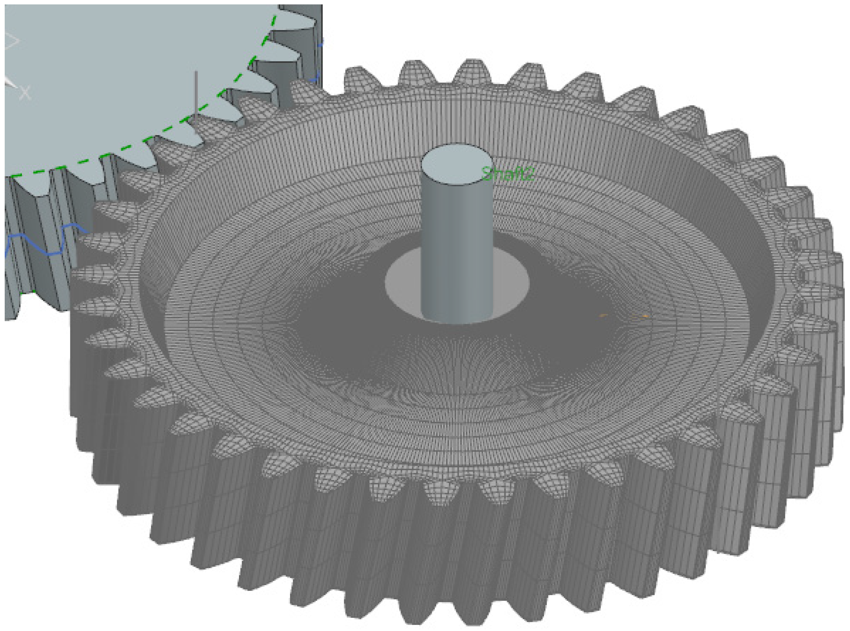
  • Finite-element (FE) modeling a gear train [12,23,24] relies on using finite elements to achieve a geometrical domain discretization and approximate the behavior of the continuous bodies through numerical integrations. It is a general modeling approach since it does not rely on any gear topologies assumption and is a first-principle-based strategy. It can account for micro- and macrogeometry deviations from the nominal operating conditions, teeth coupling, and the contacting bodies’ dynamic behavior. Nevertheless, it usually requires the fine discretization of the contacting bodies in the contact zones due to the high-stress gradients involved, and computationally expensive contact detection, which renders the FE method computationally prohibitive to use in design optimization problems.
  • Multibody (MB) modeling [25,26,27,28] is used to analyze the dynamics of systems composed of several components interconnected in space with different specifications. It enables the representation of the different bodies as rigid or deformable (flexible) components linked together through permanent (e.g., bushings) or variable (e.g., meshing gears) connection elements. It is modular, efficient (depending on the formulation and system topology), and allows for including other modeling strategies, i.e., LP and FE. Moreover, it accounts for large and complex body motions in space, macro misalignments, and microgeometry modifications [29] with respect to nominal operating and geometrical specifications. Nevertheless, it is challenging to accurately and efficiently formulate the body flexibility effects in a MB environment jointly with contact phenomena. In particular, most MB formulations are based on small (body) deformations that represent a limitation under high loading conditions.
This work relies on an advanced contact formulation already integrated within a MB tool of Siemens Simcenter Motion [30]. In particular, the floating frame of reference (FFR) formulation [31] was adopted to describe the motion of the gears in space and their interactions, resulting in the following (at most) quadratic equations of motion (EOMs):
M q q ¨ + K q + G T λ + f v + f e x t = 0 ϕ q = 0  
where q and q ¨ n q represent the generalized system coordinates and accelerations, respectively; M q is the configuration-dependent mass matrix of the system; K is the constant stiffness matrix; f v is the velocity-dependent force vector that accounts for the gyroscopic effects; f e x t is the generalized external force vector; ϕ q represents the set of constraint equations, and G = ϕ / q is the constraint Jacobian.

3.1. Advanced Contact Strategy in Multibody Simulations

If we focus on the dynamics of two generic meshing gears, the interaction phenomena governing the system dynamics are in the EOMs through generalized external forces f e x t , as depicted in Figure 3a, which can be written as:
f e x t = f 12 F 12 + f 21 F 21 + f i n T i n + f r e s T r e s
As a result of the considered boundary conditions, T i n is the input torque applied to the driving gear, whereas T r e s is the resistant torque applied to the driven gear. The remaining terms required to solve the EOMs are the action ( F 12 ) and reaction ( F 21 ) contact forces. The f · operator instead represents the projections of forces and torques onto the generalized coordinates space of the assembled MB system.
In such a context, the gear contact is solved using three steps:
  • Detecting the contact locations of the meshing bodies.
  • Formulating the amount of contact deformation (compliance) or inversely the contact stiffness.
  • Formulating the contact problem to be solved.
To deal with Points 1 and 2, the tracked tooth or teeth in contact are divided into n s 2D slices (see Figure 3b), such that an analytical contact detection is performed. The slicing approach enables a very efficient evaluation of the contact location and thus of the localized geometrical properties of the meshing gears. For each slice, the software exploits the involute gear geometries, accounting for gear misalignments in all DOFs. Moreover, microgeometry modifications of the tooth profile typically used to optimize the gear transmission error are considered at this stage.
Moreover, for each s -th slice, it is assumed that the total deformation pattern results from the superposition of three effects (see Figure 4):
  • The residual static deformation based on the Andersson and Vedmar idea is described in [32]. It is computed through an FE-based approach [21,33] where a static unit nodal load, normal to the tooth surface, is applied in a preprocessing step; subsequently, the deformation pattern is subtracted from the previous one considering the same loading condition while clamping the tooth in its middle plane. In this way, a locally incorrect solution is overcome [12].
  • The nonlinear local contact deformation is approximated as two contacting cylinders in line contact according to Hertz theory, and theWeber and Banaschek formula [34].
  • The dynamic deformation pattern is taken into account using the FE-based component mode synthesis approach [35,36,37] and creating a set of mass-orthonormalized eigenmodes.
Once the compliance model had been defined for the meshing gears, the following nonlinear contact problem was constructed for each s-th slice to link the kinematic and dynamic displacements with the related contact forces F 21 s :
δ 21 s α 21 s ( F 21 s   · n 21 s ¯ , g e o m 1 , 2 , E 1 , 2 , ν 1 , 2 ) + C 1 g e o m 1 , E 1 , ν 1 + C 2 g e o m 1 , E 1 , ν 1 F 21   · n 21 s ¯ = g F 21   · n 21 s ¯ ,   g e o m 1 , 2 , E 1 , 2 , ν 1 , 2 0
F 21   · n 21 s ¯ 0
g F 21   · n 21 s ¯ ,   g e o m 1 , 2 , E 1 , 2 , ν 1 , 2 T F 21   · n 21 s ¯ = 0
where δ is the corrected penetration for dynamic effects, misalignment, and microgeometry; C i is the residual compliance maps based on the Andersson and Vedmar approach [32]; g e o m i , E i , ν i are the geometrical properties, the Young modulus, and Poisson’s ratio of the i-th gear, respectively; n is the unit vector representing the normal to the contact surface at the contact location; α is the nonlinear Hertzian penetration described by the following Weber and Banaschek formula [34]:
α = F π l 1 ν 1 2   E 1 + 1 ν 2 2   E 2 ln 4 h 1 h 2 a 2 1 2 ν 1 1 ν 1   + ν 2 1 ν 2   .
where a is the half contact width that can be computed as
a = 4 F π l R e q 1 ν 1 2   E 1 + 1 ν 2 2   E 2 1 2 ;
h i is the half tooth thickness computed at the pitch point of the i-th gear, and R e q is the equivalent radius of curvature of the contacting cylinders:
1 R e q = 1 R 1 + 1 R 2 .
Lastly, the overall MB problem was fully defined, and the assembled EOMs of Equation (3) were solved with respect to the generalized coordinates and accelerations by means of a nonlinear iterative solver [38].

3.2. Performance Metric: Transmission Error

Although nominal gear profiles are conjugate by design, tooth and body flexibility, and other disturbing factors such as misalignment, deterioration, and micromodifications produce a slight deviation from the ideal kinematic conditions. Analysts use the transmission error (TE) to quantify the degree of offset between the ideal (or conjugate) and actual (or real) behavior of the driven gear. It is defined as the difference between the ideal kinematic motion of a gear pair and its actual realization:
T E = 1 τ Δ θ 2 Δ θ 1 ,
where Δ θ 1 and Δ θ 2 represent the angular motion of the driving and driven gears, respectively, and τ is the transmission ratio of the gear pair. For practical reasons, the TE is often reported in the equivalent linear form:
T E = r b 2 Δ θ 2 r b 1 Δ θ 1 ,
where r b 1 and r b 2 represent the base radii of the corresponding gears.
As demonstrated by Palermo et al. in [39], an interesting metric to assess the N and V performance of a geared transmission is the pick-to-pick (PtP) value of the TE, which inherently indicates the severity of parametric excitation for different levels of load and velocity occurring during the meshing cycle. The recent literature on the multiobjective optimization of macrogeometry [40,41], and combined macro- and microgeometry [42] uses the TE-related metric as an indicator of the N and V performance of geared transmissions.

4. Adopted Optimization Strategy

In complex problems such as the optimization of geared transmissions, the main challenges stand on setting up a robust framework that often requires to set up fast and reliable interconnections among several tools with different communication protocols. Moreover, due to the high nonlinear nature of contact problems in gear transmissions, efficient and accurate simulation models are required to evaluate the system performance at each design configuration.

4.1. Optimization Workflow

In this contribution, most limitations concerning the communication and solution of the optimization problem are overcome by exploiting the versatile nature of HEEDS. In addition, the optimization metrics per design are evaluated through Simcencer Motion, as described in the previous sections.
On the one hand, HEEDS receives input parameters (i.e., design variables) that are then manipulated to be compatible with the program where the selected optimization metrics are evaluated, e.g., performing a dynamic simulation in Simcenter Motion.
On the other hand, the Simcenter 3D Transmission Builder takes as input the description of the gear train in terms of its basic geometrical and topological properties, expressed according to industry standards as described in [14]. Then, a multibody model of the assembled transmission is procedurally generated within the Simcenter 3D motion environment and an advanced gear contact method [14] is considered, as described in Section 3.1, which allows for capturing relevant static and dynamic phenomena that influence the system-level behavior of the considered gear pair.
The influence of the gear crown and gear-body design is taken into account without compromising the computational efficiency of the dedicated gear-contact modules embedded in the motion solver. The results of the multibody simulations are used to compute the performance metrics required to evaluate the objective functions. Once the simulation is completed, HEEDS extracts the results and converts them back into the format that the input values previously had. The analysis of the characteristics or quantities that are optimized is entrusted to the optimization algorithm, which produces new input parameters by repeating the analysis until the stopping criteria are reached.
As depicted in Figure 5, the proposed methodology for achieving a multiobjective optimal design of a lightweight transmission is initiated by generating a baseline solution. This is achieved by means of the Simcenter 3D Transmission Builder module, which can generate the CAE models for each component of the transmission system and assemble them into the multibody model required for the quasistatic or dynamic simulations.

4.2. Alterer

In order to enable the required lightweight design parameterization and the use of the advanced contact solution in the presence of a lightweight gear body geometry, the current version of the Simcenter software requires manual intervention from highly qualified users for complementing the automatically generated FE model of the gear crown with the preferred lightweight geometry. The manually assembled FE model of the lightweight gear is given as input to the FE preprocessor, which computes the necessary information to enable the simulation of the gear contact problem.
The HEEDS software can be used to completely automate the above-described process except for the gear-body FE definition, which is still linked to manual user interaction. To overcome this issue, a set of MATLAB routines were developed forming a software package named ALTERER (Automated LighTweight gEaR body 9orphing). The latter defines the FE mesh of the lightweight gear body and automatically assembles the FE body part to the existing gear crown, starting from a set of design parameters. As a result, the program generates the assembled gear body FE input files already complying with the format expected by the FE Preprocessor.
Thanks to the obtained functionality, the HEEDS software can take the lead in orchestrating the ordered execution of all necessary modules, obtaining a fully automated evaluation process without any manual human intervention. HEEDS relies on its patented Sherpa proprietary algorithms and strategy in order to optimally and constantly tune the next decision set to be explored. As a result, the lightweight gear design space exploration process is fully automated. Moreover, HEEDS allows for aborting prematurely, pausing and restarting the optimization, or even extending it by launching a set of additional evaluations in case the analyst deems it necessary.

5. Application Case

In this section, the previously described optimization workflow and tools are applied to an industrially relevant use case: the optimization of the gear body of a helical gear pair.

5.1. Use-Case Description

In order to illustrate the application of the proposed methodology, we considered a multiobjective design of the gear pair starting from a reference or initial design. The baseline gear pair was formed by two identical gears, a driver and a driven one, and the geometrical properties are summarized in Table 1.
As depicted in Figure 6, the optimal design was limited to the driven gear while keeping the other fixed at its baseline geometry.
As illustrated in Figure 7, the driven gear was parameterized enabling the mass reduction considering only two geometrical decision variables: the Rim length and the Web thickness. For a given combination of the design variables, HEEDS orchestrates the evaluation of the objective functions by executing the evaluation pipeline described in Section 4.
Therefore, the automated design-exploration process first obtains an updated CAD model and then the corresponding FE model of the driven gear, as depicted in Figure 8. As described above, the HEEDS|MDO proprietary multiobjective Pareto search algorithm simultaneously uses multiple search strategies to more effectively explore the Pareto front. Its superior efficiency to that of other technique available in the literature was also documented in [43]. Table 2 summarizes the interval ranges used for the reported study.
Additionally, the optimization problem was formulated to minimize the total mass of the driven gear while reducing the peek-to-peek value of the TE under dynamic conditions and for different levels of the transmitted torque.
To avoid convergence problems, the driver gear was enforced to reach the desired speed value of 10 rpm by following a ramp of one-second duration (as illustrated in Figure 9) while applying a specific resistant torque to the driven gear. The ramp also allows for simulating a more realistic scenario representing a motor from which the torque is taken and gradually transmitted to the gear through a clutch or simply the time required to overcome the system’s inertia.

5.2. Optimization Results

Figure 10 shows the results obtained using the methodology under investigation for three levels of the driving torque: 50, 100, and 200 nm. As expected, increasing the torque had a direct and proportional impact on the PtP value of the TE. For each analyzed level of torque, we could observe two clusters of solutions. The first cluster contained all those solutions starting from the baseline and moving in the direction of reducing the mass while mildly compromising PtP performance: in this cluster, the two conflicting design goals were reflected in a typical hyperbolic trend. Interestingly, a second cluster of solutions appeared when looking at the leftmost side of the chart. Below 0.9 kg of mass, different hyperbolic branches dominated the Pareto front, featuring the possibility of substantially improving PtP performance while also reducing the mass of the gear.
The results of MOP analysis are summarized in Table 3. From each Pareto front, two extreme solutions were extracted for further analysis: solutions PF-A, which were selected as the best compromise along the Pareto Front, and solutions PF-B were selected as the best PtP solution; thus, they are at the bottom corner of each Pareto front.
The computational time required for the optimization of the gear pair ranged between 54.75 h for the 100 nm case and 69.95 h for the 200 nm case, with an average computational time per evaluated design of 10.84 and 13.94 min, respectively. The computational overhead of executing HEEDS proved to be minimal compared to the complexity of the simulation software used for the evaluation of the objective function. All examples were computed using a commodity laptop featuring an Intel Core i7-h and 12 GB RAM.

6. Conclusions

Fueled by recent advances in the field of FE-based contact analysis, this paper extended the usage of modern design exploration software to the field of lightweight gear transmissions. The envisioned methodology was built on top of existing state-of-the-art commercial solutions. HEEDS and its patented SHERPA multiobjective search algorithms were used to efficiently explore the Pareto front in case of multiobjective design space exploration problems. Simcenter 3D, comprising the FE-preprocessor and the Transmission Builder functionalities, was used because its hybrid FE–analytical approach offers the best-in-class numerical efficiency in terms of gear contact problem simulations. As part of this study, ad hoc procedures were developed to eliminate human intervention from the evaluation pipeline, leading to a fully automated evaluation process.
The proposed methodology was tested by considering the multiobjective design space exploration of helical gear transmission. Three levels of torque were also used to analyze the impact of the loading conditions on the obtained results. For each subcase, a Pareto front appeared at the bottom-left corner of each chart, featuring the hyperbolic shape typical of competing goals scenarios.
As summarized in Table 3, solutions PF-A and PF-B extracted from each of the Pareto fronts, corresponded to realizations of the same design parameters, suggesting that the optimal results obtained for one torque level were robust enough to maintain optimality within the considered torque variations. Further investigations are required to assess the validity of such findings on a more methodological level.
Future works will further expand the proposed approach by considering different types of lightweight gears, eventually combining micro- and macrogeometrical parameters with topological choice variables, such as the type and number of holes in the gear body.

Author Contributions

Conceptualization, F.C., R.A., L.M., A.R. and D.M.; methodology, F.C., L.M., A.R. and D.M.; software, F.C.; validation, F.C., R.A. and L.M.; formal analysis, F.C., R.A., L.M., A.R. and D.M.; investigation, F.C., R.A., L.M., A.R. and D.M.; resources, A.R. and D.M.; data curation, F.C., R.A., L.M., A.R. and D.M.; writing—original draft preparation, F.C., R.A. and D.M.; writing—review and editing, F.C., R.A., A.R. and D.M.; visualization, F.C. and R.A.; supervision, A.R. and D.M.; project administration, A.R. and D.M.; funding acquisition, A.R. and D.M. All authors have read and agreed to the published version of the manuscript.

Funding

This research was funded by VLAIO (Flemish government agency Flanders Innovation and Entrepreneurship), R&D project BE QUIET no. HBC.2019.

Institutional Review Board Statement

Not applicable.

Informed Consent Statement

Not applicable.

Data Availability Statement

Not applicable.

Acknowledgments

The authors kindly acknowledge VLAIO (Flemish government agency Flanders Innovation and Entrepreneurship) for their support of the R&D project BE QUIET (BElgian consortium for QUIEt Transmissions, no. HBC.2019.2323), coordinated by Siemens Digital Industries Software, Belgium.

Conflicts of Interest

The authors declare no conflict of interest.

References

  1. Dobrzański, L.; Tański, T.; Čížek, L.; Brytan, Z. Structure and properties of magnesium cast alloys. J. Mater. Process. Technol. 2007, 192–193, 567–574. [Google Scholar] [CrossRef]
  2. New Equipment Digest. NASA’s Revolutionary Hybrid Gear Lightens Your Load. Available online: https://www.newequipment.com/research-and-development/article/22058083/nasas-revolutionary-hybrid-gear-lightens-your-load (accessed on 10 June 2022).
  3. Ohrn, K.E. Aircraft Energy Use. In Encyclopedia of Energy Engineering and Technology, 2nd ed.; CRC Press: Boca Raton, FL, USA, 2014; pp. 32–38. [Google Scholar] [CrossRef]
  4. Shweiki, S.; Palermo, A.; Mundo, D. A Study on the Dynamic Behaviour of Lightweight Gears. Shock Vib. 2017, 2017, 7982170. [Google Scholar] [CrossRef]
  5. Benaïcha, Y.; Mélot, A.; Rigaud, E.; Beley, J.-D.; Thouverez, F.; Perret-Liaudet, J. A decomposition method for the fast computation of the transmission error of gears with holes. J. Sound Vib. 2022, 532, 116927. [Google Scholar] [CrossRef]
  6. Catera, P.G.; Mundo, D.; Gagliardi, F.; Treviso, A. A comparative analysis of adhesive bonding and interference fitting as joining technologies for hybrid metal-composite gear manufacturing. Int. J. Interact. Des. Manuf. 2020, 14, 535–550. [Google Scholar] [CrossRef]
  7. Yang, J.; Zhang, Y.; Lee, C.-H. Multi-parameter optimization-based design of lightweight vibration-reduction gear bodies. J. Mech. Sci. Technol. 2022, 36, 1879–1887. [Google Scholar] [CrossRef]
  8. Ramadani, R.; Belsak, A.; Kegl, M.; Predan, J.; Pehan, S. Topology Optimization Based Design of Lightweight and Low Vibration Gear Bodies. Int. J. Simul. Model. 2018, 17, 92–104. [Google Scholar] [CrossRef]
  9. Hou, L.; Lei, Y.; Fu, Y.; Hu, J. Effects of Lightweight Gear Blank on Noise, Vibration and Harshness for Electric Drive System in Electric Vehicles. Proc. Inst. Mech. Eng. Part K J. Multi-Body Dyn. 2020, 234, 447–464. [Google Scholar] [CrossRef]
  10. Shweiki, S.; Rezayat, A.; Tamarozzi, T.; Mundo, D. Transmission Error and strain analysis of lightweight gears by using a hybrid FE-analytical gear contact model. Mech. Syst. Signal Process. 2019, 123, 573–590. [Google Scholar] [CrossRef]
  11. Vivet, M.; Tamarozzi, T.; Desmet, W.; Mundo, D. On the modelling of gear alignment errors in the tooth contact analysis of spiral bevel gears. Mech. Mach. Theory 2021, 155, 104065. [Google Scholar] [CrossRef]
  12. Cappellini, N.; Tamarozzi, T.; Blockmans, B.; Fiszer, J.; Cosco, F.; Desmet, W. Semi-analytic contact technique in a non-linear parametric model order reduction method for gear simulations. Meccanica 2017, 53, 49–75. [Google Scholar] [CrossRef]
  13. Simcenter. HEEDS. Available online: https://www.plm.automation.siemens.com/global/en/products/simcenter/simcenter-heeds.html (accessed on 22 June 2022).
  14. Siemens PLM Software. Boosting Productivity in Gearbox Engineering Using a Revolutionary Approach to Multibody Simulation. Available online: https://resources.sw.siemens.com/en-US/white-paper-gearbox-multibody-simulation (accessed on 22 June 2022).
  15. Simcenter 3D Motion: Siemens PLM Software. Advanced FE-Preprocessor. Available online: https://www.plm.automation.siemens.com/global/en/products/simcenter/simcenter-3d.html (accessed on 22 June 2022).
  16. Cai, Y.; Hayashi, T. The Linear Approximated Equation of Vibration of a Pair of Spur Gears (Theory and Experiment). J. Mech. Des. 1994, 116, 558–564. [Google Scholar] [CrossRef]
  17. Cai, Y. Simulation on the Rotational Vibration of Helical Gears in Consideration of the Tooth Separation Phenomenon (A New Stiffness Function of Helical Involute Tooth Pair). J. Mech. Des. 1995, 117, 460–469. [Google Scholar] [CrossRef]
  18. Parker, R.G.; Vijayakar, S.M.; Imajo, T. Non-linear dynamic response of a spur gear pair: Modelling and experimental comparisons. J. Sound Vib. 2000, 237, 435–455. [Google Scholar] [CrossRef]
  19. Shweiki, S.; Korta, J.; Palermo, A.; Adduci, R.; Mundo, D. Combining Finite Element Analysis and Analytical Modelling for Efficient Simulations of Non-Linear Gear Dynamics. In Proceedings of the 7th European Congress on Computational Methods in Applied Sciences and Engineering, Crete Island, Greece, 5–10 June 2016. [Google Scholar]
  20. ISO. ISO 6336-1:1996—Calculation of Load Capacity of Spur and Helical Gears—Part 1: Basic Principles, Introduction and General Influence Factors. Available online: https://www.iso.org/standard/12632.html (accessed on 20 June 2022).
  21. Shen, Y.; Yang, S.; Liu, X. Nonlinear dynamics of a spur gear pair with time-varying stiffness and backlash based on incremental harmonic balance method. Int. J. Mech. Sci. 2006, 48, 1256–1263. [Google Scholar] [CrossRef]
  22. Vivet, M.; Mundo, D.; Tamarozzi, T.; Desmet, W. An analytical model for accurate and numerically efficient tooth contact analysis under load, applied to face-milled spiral bevel gears. Mech. Mach. Theory 2018, 130, 137–156. [Google Scholar] [CrossRef]
  23. Blockmans, B.; Adduci, R.; Fiszer, J.; Cappellini, N.; Desmet, W. Finite Element Based Simulation of Planetary Gearboxes Using Model-Order Reduction. In Proceedings of the International Gear Conference, Lyon, France, 29 August 2018; Chartridge Books: Oxford, UK, 2018; pp. 1024–1033. [Google Scholar]
  24. Korta, J.A.; Mundo, D. Multi-objective micro-geometry optimization of gear tooth supported by response surface methodology. Mech. Mach. Theory 2017, 109, 278–295. [Google Scholar] [CrossRef]
  25. Blockmans, B. Model Reduction of Contact Problems in Flexible Multibody Dynamics with Emphasis on Dynamic Gear Contact Problems; KU Leuven: Leuven, Belgium, 2018. [Google Scholar]
  26. Vivet, M.; Verhoogen, J.; Jiránek, P.; Tamarozzi, T. A New Gear Contact Method for the Tooth Contact Analysis of Spiral Bevel Gear Drives in Multibody Simulations. In Proceedings of the NAFEMS International Seminar Advances in Structural Dynamic Simulation, Online, 29–30 March 2022. [Google Scholar]
  27. Tamarozzi, T.; Blockmans, B.; Desmet, W. Dynamic Stress Analysis of the High-Speed Stage of a Wind Turbine Gearbox Using a Coupled Flexible Multibody Approach. In Proceedings of the Conference for Wind Power Drives 2015, Aachen, Germany, 10–12 March 2015; Books on Demand: Canfield, OH, USA, 2018; p. 87. [Google Scholar]
  28. Palermo, A.; Mundo, D.; Hadjit, R.; Desmet, W. Multibody element for spur and helical gear meshing based on detailed three-dimensional contact calculations. Mech. Mach. Theory 2013, 62, 13–30. [Google Scholar] [CrossRef]
  29. Litvin, F.L.; Fuentes, A. Gear Geometry and Applied Theory, 2nd ed.; Cambridge University Press: Cambridge, UK, 2004; ISBN 9780521815178. [Google Scholar]
  30. Siemens. White Paper: Boosting Productivity in Gearbox Engineering; 2019; Available online: http://www.fp7demetra.eu/images/files/Siemens-PLM-Boosting-Productivity-in-Gearbox-Engineering-wp-65217-A20.pdf (accessed on 30 July 2022).
  31. Shabana, A.A. Dynamics of Multibody Systems, 5th ed.; Cambridge University Press: Cambridge, UK, 2020; ISBN 1108485642. [Google Scholar]
  32. Andersson, A.; Vedmar, L. A dynamic model to determine vibrations in involute helical gears. J. Sound Vib. 2003, 260, 195–212. [Google Scholar] [CrossRef]
  33. Heirman, G.; Cappellini, N.; Tamarozzi, T.; Toso, A. Contact Modeling between Objects. US Patent 10,423,730, 24 September 2019. [Google Scholar]
  34. Weber, C.; Banaschek, K.; Niemann, G. Formänderung und Profilrücknahme Bei Gerad-und Schrägverzahnten Rädern; F. Vieweg: Brunswick, Germany, 1955. [Google Scholar]
  35. Craig, R.R.; Bampton, M.C.C. Coupling of substructures for dynamic analyses. AIAA J. 1968, 6, 1313–1319. [Google Scholar] [CrossRef] [Green Version]
  36. Agrawal, O.P.; Shabana, A.A. Dynamic analysis of multibody systems using component modes. Comput. Struct. 1985, 21, 1303–1312. [Google Scholar] [CrossRef]
  37. Blockmans, B.; Tamarozzi, T.; Naets, F.; Desmet, W. A nonlinear parametric model reduction method for efficient gear contact simulations. Int. J. Numer. Methods Eng. 2015, 102, 1162–1191. [Google Scholar] [CrossRef]
  38. Ascher, U.M.; Petzold, L.R. Computer Methods for Ordinary Differential Equations and Differential-Algebraic Equations; Siam: Philadelphia, PA, USA, 1998; Volume 61. [Google Scholar]
  39. Palermo, A.; Britte, L.; Janssens, K.; Mundo, D.; Desmet, W. The measurement of Gear Transmission Error as an NVH indicator: Theoretical discussion and industrial application via low-cost digital encoders to an all-electric vehicle gearbox. Mech. Syst. Signal Process. 2018, 110, 368–389. [Google Scholar] [CrossRef]
  40. Choi, C.; Ahn, H.; Park, Y.J.; Lee, G.H.; Kim, S.C. Influence of gear tooth addendum and dedendum on the helical gear optimization considering mass, efficiency, and transmission error. Mech. Mach. Theory 2021, 166, 104476. [Google Scholar] [CrossRef]
  41. Kim, S.-C.; Moon, S.-G.; Sohn, J.-H.; Park, Y.-J.; Choi, C.-H.; Lee, G.-H. Macro geometry optimization of a helical gear pair for mass, efficiency, and transmission error. Mech. Mach. Theory 2020, 144, 103634. [Google Scholar] [CrossRef]
  42. Garambois, P.; Perret-Liaudet, J.; Rigaud, E. NVH robust optimization of gear macro and microgeometries using an efficient tooth contact model. Mech. Mach. Theory 2017, 117, 78–95. [Google Scholar] [CrossRef] [Green Version]
  43. Chase, N.; Rademacher, M.; Goodman, E.; Averill, R.; Sidhu, R. A Benchmark Study of Multi-Objective Optimization Methods. BMK-3021 Rev. 2009, 6, 1–24. [Google Scholar]
Figure 1. Example of a Pareto front.
Machines 10 00779 g001
Figure 2. HEEDS graphical user interface.
Machines 10 00779 g002
Figure 3. Contact problem: (a) external forces acting on the meshing gears; (b) slicing approach.
Machines 10 00779 g003
Figure 4. Computation of the required amount of deflection.
Machines 10 00779 g004
Figure 5. Multiobjective lightweight design: flowchart.
Machines 10 00779 g005
Figure 6. CAD model of the considered lightweight gear transmission: the multiobjective design optimization was formulated by removing material from the body of the driven gear while maintaining the driving one in its full configuration.
Machines 10 00779 g006
Figure 7. Lightweight gear’s geometry, parametrically controlled by varying two decision variables: rim length and web thickness.
Machines 10 00779 g007
Figure 8. FE model of the lightweight driven gear.
Machines 10 00779 g008
Figure 9. Angular velocity profile assigned to driver gear.
Machines 10 00779 g009
Figure 10. PtP vs. mass trend for different values of torque: (a) 50 nm; (b) 100 nm; (c) 200 nm.
Machines 10 00779 g010
Table 1. Gears design specifications.
Parameter NameBaseline Gears
Teeth number40
Normal module (m)2.5 mm
Normal pressure angle20 deg
Helical angle10 deg
Tooth width20 mm
Addendum1
Dedendum1.25
Working center distance101.6 mm
Rim width-
Web thickness20 mm
Table 2. Design variables ranges.
Decision VariableMinMaxBaseline
Web thickness (mm)52020
Rim length (mm)36.2543.7543.75
Table 3. Optimal design Results.
Design ParametersDesign Goals
Web
Thickness
Rim
Length
MassPtP
(kg)(%)50 nm100 nm200 nm
(mm)(mm)(μm)(%)(μm)(%)(μm)(%)
Baseline2043.751.205 0.75 1.35 2.54
PF-A6.0443.750.691−42.7% 0.61.−19.0%1.09−19.1%2.14−15.7%
PF-B5.60400.780−35.3%0.53 −29.3%0.99−26.3%1.84−27.6%
Publisher’s Note: MDPI stays neutral with regard to jurisdictional claims in published maps and institutional affiliations.

