Article

Research on Unbalanced Vibration Suppression Method for Coupled Cantilever Dual-Rotor System

1
Key Laboratory of Engine Health Monitoring-Control and Networking of Ministry of Education, Beijing University of Chemical Technology, Beijing 100029, China
2
Beijing Key Laboratory of High-end Mechanical Equipment Health Monitoring and Self-Recovery, Beijing University of Chemical Technology, Beijing 100029, China
*
Author to whom correspondence should be addressed.
Machines 2022, 10(9), 758; https://doi.org/10.3390/machines10090758
Submission received: 9 July 2022 / Revised: 29 August 2022 / Accepted: 29 August 2022 / Published: 1 September 2022
(This article belongs to the Special Issue Noise and Vibration Control in Dynamic Systems)

Abstract

:
The cantilever dual-rotor system is a typical structure of the blade output end of the open rotor engine and the coaxial output turboshaft engine. The excessive unbalanced vibration of a coupled cantilever dual-rotor system is one of the main factors limiting the application of the above engine type. In order to accurately describe the vibration coupling effect between the dual-rotor-intermediate bearings, the unbalanced response of the cantilever dual-rotor system is analyzed, and the self-sensitivity coefficient is proposed to guide the selection of measuring points and vibration suppression experiments for the dual-rotor system. On this basis, a new online automatic balance actuator applicable to this dual-rotor system is designed, and a feasibility experiment is carried out. The experimental results indicate that: (1) The self-sensitivity coefficient can be used as the basis for the actual vibration measuring point arrangement and unbalanced vibration suppression strategy of the dual-rotor system, and the proposed step-by-step vibration suppression strategy can reduce the vibration of the dual-rotor system by more than 80%. (2) The designed online automatic balance actuator can reduce the unbalanced vibration by 53% in 3.52 s. The proposed method in this study can provide guidance for the vibration suppression of the dual-rotor system.

Graphical Abstract

1. Introduction

The traditional coaxial dual-rotor system with a high-pressure rotor and low-pressure rotor is widely used in the field of aero engines. However, the cantilever coaxial dual-rotor system at the output of open rotor engines and the coaxial output turboshaft engines has limited application. The power of the open rotor engine and the coaxial output turboshaft engines is output to the planetary gear reducer through the power turbine. Then, the power is distributed by the planetary gear reducer to the two output shafts, which drive the propeller rotation. It should be noted that the inner and outer rotors system at the output end is cantilevered. The inner and outer rotors are connected by intermediate bearings, and their vibration response affects each other, leading to the vibration coupling of the dual-rotor-support-casing system. The unbalanced vibration of the rotor system is a crucial factor affecting the reliability of the aero engine. Significant stresses and deformations can be caused by excessive unbalance, which can loosen the connections, load the bearings beyond the allowable range, and damage the engine [1,2]. In order to reduce the engine vibration and improve the safety, reliability, and lifetime of the engine, it is necessary to study the unbalanced vibration mechanism, vibration suppression strategy, and vibration suppression method for the dual-rotor system.
At present, enormous research has been conducted on the dynamic characteristics, vibration coupling mechanisms, and vibration suppression of aero-engine dual-rotor systems by scholars. The analysis of the dynamic characteristics and vibration mechanism is the key to the aero-engine design and intelligent maintenance. In engineering, perfect dynamic balance does not exist, and the rotor misalignment problem is inevitable due to the coupling. For this reason, Wang et al. derived the dynamics equations of the unbalance–misalignment coupling fault of the dual-rotor system by using modern nonlinear dynamics theory to derive dynamics equations for the unbalance–misalignment coupling fault of the dual rotor system. The influence of different rotational speeds, eccentricity, and parallel eccentricity on the vibration response of the dual-rotor system was analyzed [3]. Considering the coupling effect of an intermediate bearing, Ma Pingping et al. studied the effects of the unbalance position, unbalanced size, phase, and intermediate bearing stiffness on the vibration characteristics of the dual-rotor system and revealed the vibration response law, vibration transmission law, and vibration sensitivity of the rotor system caused by the vibration coupling of the inner and outer rotors in unbalancing [4]. The coupling of dynamic characteristics between the dual-rotor system is caused by intermediate bearings. Ma Yanhong et al. studied and quantitatively evaluated the coupling characteristics of the dual rotor system, and obtained the correlation between the characteristic structural parameters such as the intermediate bearing position and the coupled vibration characteristics of the system [5]. A coupled vibration control method, based on the modal superposition principle for the response of the dual-rotor system, was proposed. Rolling bearings are the primary support of an aero-engine dual-rotor system. Ma Xingxing et al. analyzed the effects of ball bearing clearance, unbalance, concentrated spring stiffness, and oil film clearance of a squeezed oil film damper on the nonlinear steady-state response of a dual-rotor system [6]. Lu et al. investigated the influence of an aero-engine’s rolling bearing radial clearance, vertical force, and speed ratio on the nonlinear response of the dual-rotor system [7,8]. The turbine-shared support structures have broad applications in aero engines, but the related research is scarce. Han et al. investigated the coupled vibration response of the squeezed film damper–rotor–bearing system with a turbine’s shared-support dual-rotor structure at different differential speed ratios [9].
Vibration suppression is a difficult problem in the operation and maintenance of aero engines. Therefore, vibration suppression research, in both passive and active control, has been performed by scientists in various countries. To reduce maintenance costs and data processing, Shamsah et al. reduced the number of acceleration sensors from two to one for rotor unbalance measurement [10]. Aiming at reducing the excessive vibration of aero engines affected by the assembly quality, Chen et al. established an optimization function with the assembly angle as the optimization variable and the maximum vibration velocity at the bearing as the optimization objective. Then, the high-pressure rotor system was assembled based on the optimal assembly angle calculated by simulation, and the assembly accuracy was improved to suppress rotor vibration [11]. For the near-frequency separation problem in the dynamic balancing process of the dual-rotor system, Ponci and Zhang et al., respectively, proposed the method of increasing the sampling time method, the nonwhole beat correlation method, and the whole beat correlation method to separate the inner and outer rotor unbalances and then perform dynamic balancing [12,13,14]. The vibration suppression method mentioned in the above literature is passive control. How to make the equipment perform active vibration control during operation is also a research hot topic. Fang and Gong et al. used electromagnetic bearings to suppress rotor unbalance vibration online and in real-time [15,16]. Fan and Pan et al. designed an electromagnetic automatic balance actuator based on the axial excitation and radial excitation principles, respectively [17,18]. The effectiveness of the automatic balance actuator was verified by experiments. For large rotors operating at high speeds, Zhang and Pan et al. proposed liquid-driven and gas-driven automatic balance actuators, which achieved a significant vibration suppression effect in the simulation test bed [19,20]. Although electromagnetic bearings and automatic balance actuators based on electromagnetic, liquid-driven, and gas-driven have significant vibration suppression effects, none of these actuators are suitable for application in aero engines. Therefore, Airbus proposed a motor-based automatic balance actuator that can be used in open rotor engines in 2015 [21].
Regarding the research on the unbalanced coupling vibration suppression of the dual-rotor system, the vibration coupling mechanism of the dual-rotor system and the vibration suppression strategy have not been combined by scholars. In terms of the research objects concerned, scholars have studied the high-pressure rotor and low-pressure rotor in the core of turbofan engines or turboshaft engines, and there is no relevant research on the internal and external dual-rotor system at the output end of the open rotor engine or the turboshaft engine. In addition, very few scholars have studied online automatic balance actuators applicable to aero engines. Therefore, in this paper, a dynamic model called “coaxial counter-rotating cantilever dual-rotor system” for the output rotor system of an open rotor engine was established, its coupling vibration mechanism was analyzed, and a set of new motor-based online automatic balance actuator suitable for aero engines was designed. Finally, an unbalanced coupling vibration suppression experiment and a feasibility experiment of the automatic balance actuator were carried out on the simulated test rig.

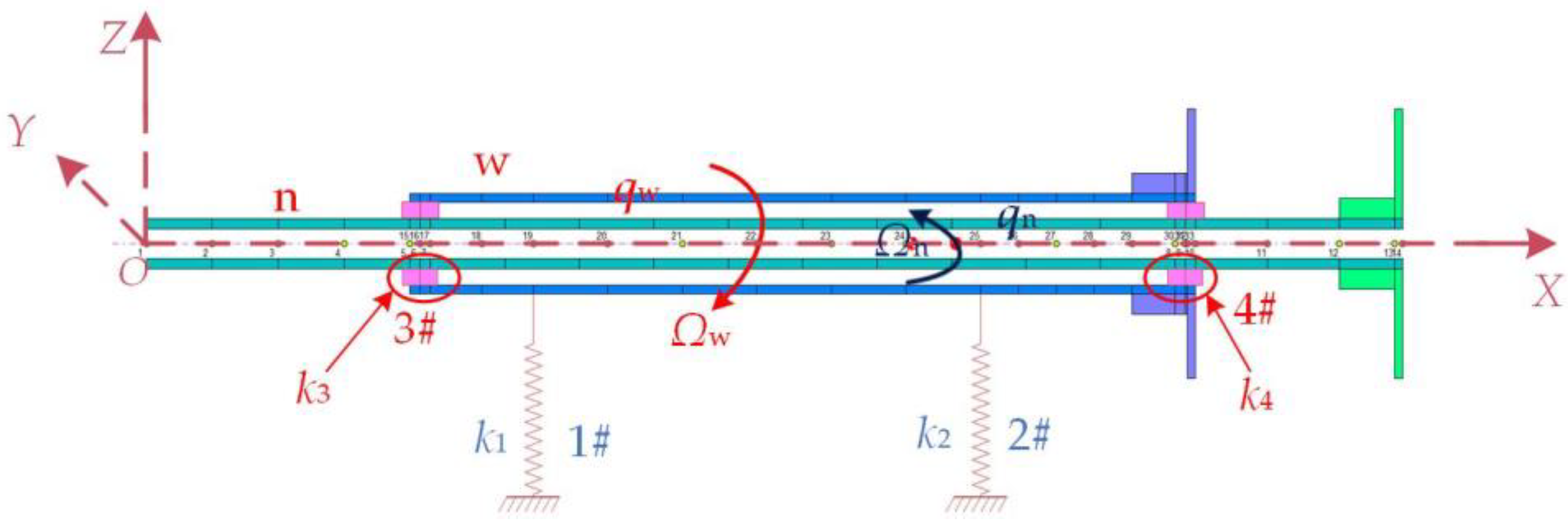
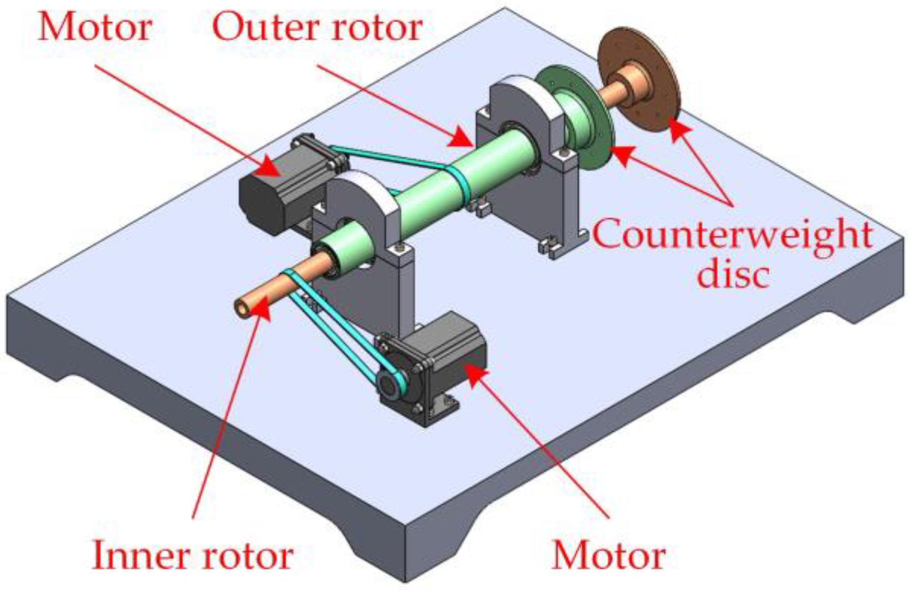
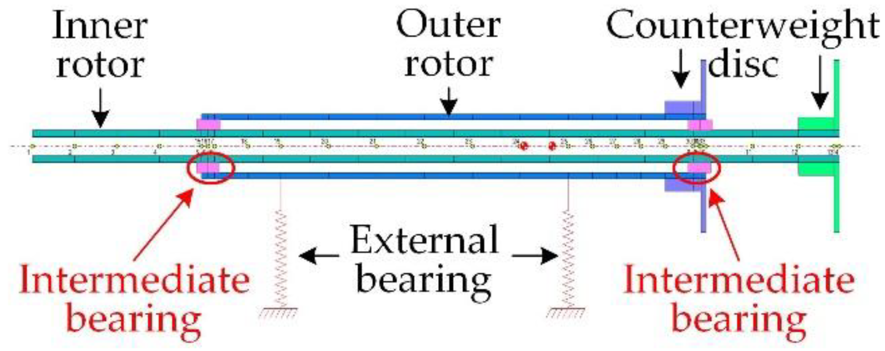
2. Structural Characteristics of the Cantilevered Coaxial Counter-Rotating Dual-Rotor System

The dual-rotor coupling structure is widely used in aero engines. The typical dual-rotor aero-engine structure is mainly composed of the low-pressure rotor and high-pressure rotor. The low-pressure rotor is composed of a low-pressure compressor and a low-pressure turbine, and the high-pressure rotor is composed of a high-pressure compressor and a high-pressure turbine. The counter-rotating dual-rotor structure can reduce the influence of rotor gyroscopic moment, improve the aero engine’s surge margin and the efficiency of the compressor, and reduce the number of guide vanes to reduce the weight of the engine, reduce the load on the casing, and further improve aircraft maneuverability.
In addition to the dual-rotor system commonly found in turbofan and turbojet engines, there are some special coaxial counter-rotating dual-rotor aero engines for helicopters, transport aircraft, and bombers, such as the open-rotor engines from Ukraine, Rolls-Royce (UK), GE (USA), Boeing (USA) and SNECNA (France) [22,23,24,25]. The dual-rotor structure is connected to the aero engine core through a planetary reducer, and the output end is connected with the propeller in a cantilever structure. The research objects of this paper are the cantilevered coaxial counter-rotating dual-rotor systems of the open-rotor engine.
The coaxial counter-rotating dual-rotor structure at the output end of an open-rotor engine is shown in Figure 1. The power turbine outputs power through the planetary reducer, and the inner and outer rotors rotate at reverse microdifferential speed. The inner rotor is connected to the sun wheel and supported by the 3# and 4# intermediate bearings on the inner wall of the outer rotor. The outer rotor is connected to the reducer ring gear, supported by the 1# and 2# bearings. The output structure is cantilevered, and the inner rotor is fully supported on the inner wall of the outer rotor without external support.
The automatic balance actuator of the inner and outer rotor is placed at the inner and outer rotor fan end near the paddle hub and connected to the intelligent controller through the signal transmission device to form the dual-rotor automatic balance system. The intelligent controller contains signal processing, dynamic balancing algorithm, and control strategy, with real-time monitoring, unbalance calculation, and actuator control command output function. The controller command is received by actuators and then makes the compensation mass disk run to the target position to generate a synthetic compensation mass to suppress unbalanced vibration caused by mass unbalance in real time. The cantilevered coaxial dual-rotor automatic balance system is demonstrated in Figure 2. At present, the dual-rotor automatic balance system has some research difficulties, such as a slow signal acquisition and complex control strategy.

3. Dynamic Characteristic Analysis of Dual-Rotor System

3.1. Equations of Motion for a Dual-Rotor System

For the coaxial counter-rotating cantilevered dual-rotor structure system, the equivalent dynamics model shown in Figure 3 was established. k1, k2, k3, and k4 denote the bearing stiffness of the 1#, 2#, 3#, and 4# supports, respectively, qw and qn are the displacement vectors of the outer and inner rotors, w and n denote the outer rotor and inner rotor, respectively. Ωw and Ωn are the rotation speeds of the outer and inner rotors, and the aerodynamic load was not considered in the model. The equivalent dynamic equations of the dual-rotor system were established based on the finite element method.
The axis element was defined as the Timoshenko beam, and the equation of motion of the unit in a fixed coordinate system was as follows [26,27]:
M ρ e + Μ I e q ¨ e Ω G e q ˙ e + K e q e = F e _ out ,
where M ρ e is the mass matrix, M I e is the mass inertia matrix, G e is the gyroscopic matrix, K e is the stiffness matrix, F e _ out is the external force on the unit, and q e is the generalized displacement vector. Each axis element had two nodes, and each node had two directions of displacement and two directions of rotation. In the subsequent assembly of the axis element matrix, since a node was shared by two adjacent axis elements, the coefficient matrices corresponding to the shared node needed to be superimposed. The number of degrees of freedom was 4 in a node, so the number of degrees of freedom of each axis element was 8. Therefore, the generalized displacement vector was as follows:
q e = q y 1 q z 1 θ y 1 θ z 1 q y 2 q z 2 θ y 2 θ z 2 T ,
where q y 1 and q y 2 are the displacements of both ends of the axis element in the Y direction, q z 1 and q z 2 are the displacements of both ends of the axis element in the Z direction, θ y 1 and θ y 2 are the rotation angles of the two ends of the axis unit around the Y-axis, θ z 1 and θ z 2 are the rotation angles of the two ends of the axis unit around the Z-axis.
Considering that the bearings used in the simplified rotor model were deep groove ball bearings and the rotor was isotropic, the damping and cross stiffness of the bearings were not considered. Therefore, the motion equation of ordinary bearings, 1# and 2# supports was as follows:
k i 0 0 0 0 k i 0 0 0 0 0 0 0 0 0 0 q y i q z i 0 0 = F y i _ out F z i _ out 0 0 , i = 1 , 2
where F y i _ out and F z i _ out denotes the external force at the bearing in Y direction and Z direction. The rotor system is isotropic, so k i (i = 1,2) denotes the principal stiffness of the 1# and 2# supports, q y i and q z i denote the displacement of the 1# and 2# bearings in the Y direction and Z direction, respectively. Since there was only one node at the location of the bearing, there were displacements in two directions at the node, but there was no rotation angle, so the number of degrees of freedom of the bearing node was 2. However, considering the convenience of the subsequent rotor system assembly, the above matrices were all expressed as 4th-order matrices.
The intermediate shaft bearing force satisfies:
F j n _ out + F j w _ o u t = 0 , ( j = 3 , 4 )
where F j n _ out and F j w _ out represent the interaction force between the outer rotor and the inner rotor in the 3# and 4# bearings, respectively. When considering the equation of motion of the dual-rotor system, the inner and outer rotors are not adjacent to each other at the intermediate bearing node, so the interaction force does not need to be counteracted by each rotor directly and should be calculated separately by the external force. Therefore, the motion equation of the intermediate bearing can be expressed as:
k j 0 k j 0 0 k j 0 k j k j 0 k j 0 0 k j 0 k j u n v n u w v w = F j n _ out F j w _ out ,
where u n and u w , respectively, represent the displacement of the intermediary bearing node in the horizontal direction of the inner and outer rotors, and v n and v w , respectively, represent the displacement of the intermediary bearing node in the vertical direction of the inner and outer rotors.
According to the structure of the dual-rotor system, it was divided into N elements, and the number of corresponding nodes was N + 2. Each element was expressed according to the above equations, and then the mass matrix, gyroscopic matrix, stiffness matrix, and bearing stiffness expression matrix of all beam units were assembled (due to the limited space, this paper does not present the assembled system in detail) to obtain the dynamic equations of the dual-rotor system, whose dynamic equations can be expressed as [28]:
M q ¨ Ω n G n + Ω w G w q ˙ + K q = F out ,
where Ω n and Ω w are the internal and external rotor speeds, respectively, q denotes the generalized displacement vector of the system, F out is the generalized force vector of the system, M is the mass matrix of the system, G n and G w represent the gyroscopic matrix of the inner and outer rotors, respectively, and K is the stiffness matrix of the system.

3.2. Unbalanced Steady-State Response Analysis of a Dual-Rotor System

According to the structure shown in Figure 1, a cantilever dual-rotor test bench was designed as shown in Figure 4. In order to adjust the relative position of the inner and outer rotors, the rotor was designed as a bare shaft with the following parameters: the inner diameter of the inner rotor was 18 mm, the outer diameter was 30 mm, and the length was 800 mm. The inner diameter of the outer rotor was 50 mm, the outer diameter was 60 mm, and the length was 500 mm. The inner and outer rotors and counterweight discs were made of 45 steel with a mass density of 7850 kg/m3, a modulus of elasticity of 206,000 N/mm2, and a shear modulus of 79,230.8 N/mm2.
DyRoBeS (Dynamics of Rotor-Bearing Systems) software was used for the finite element modeling of the dual-rotor system. Considering that the counterweight disc was a rigid disc, the counterweight disc and the rotor were modeled as a whole. The bearings used in the test rig were deep groove ball bearings, so their damping and cross stiffness were ignored in the modeling. The finite element model of the cantilevered dual-rotor system is shown in Figure 5, containing two rotors and four bearings, with a total of 31 elements, 33 nodes, and 132 degrees of freedom.
Performing a critical speed analysis of this specific rotor in DyRoBeS, Figure 6a revealed the lowest critical speed of 4851 rpm, Figure 6b revealed the second-order critical speed of 8515 rpm. The highest speed of the test bench designed in this study was 1100 r/min. The rotor can be considered as rigid in this speed range.
The steady-state response of different nodes was analyzed to determine the sensitivity of each node to unbalance so as to provide guidance for the establishment of actual measurement points. Here, firstly, the letter n was defined to represent the ratio between the outer rotor speed and the inner rotor speed. A positive n meant that the rotation direction of the inner and outer rotors was the same, and a negative n meant that the rotation direction of the inner and outer rotors was opposite. Under the condition of n = −1.5, the same size of unbalance was applied to the inner and outer rotor counterweight discs, respectively, in this section, and the unbalance response was obtained by a steady-state analysis at each measurement point. According to the test bench, the eddy current sensor locations were at the proposed inner rotor nodes 2, 4, and 11 and at the outer rotor nodes 26, 27, and 28, as the available measurement points of the sensor. Measuring point 1 corresponded to node 2, measuring point 2 corresponded to node 4, measuring point 3 corresponded to node 11, measuring point 4 corresponded to node 26, measuring point 5 corresponded to node 27, measuring point 6 corresponded to node 28, and the specific measuring points were as shown in Figure 7.
By adding the same unbalance mass to the inner and outer counterweight disks, respectively, the steady-state response of the dual rotor system at different measuring points under the unbalanced force was studied. The unbalance of the simulation was 2599 gmm, and the measured response corresponded to a speed of 1000 r/min (inner rotor speed). When the inner rotor was unbalanced, the steady-state response of each measured point was as shown in Figure 8a. When the unbalance was on the outer rotor, the steady-state response of each measured point was similar to Figure 8a. The unbalanced vibration response under all operating conditions is shown in Figure 8b, and the corresponding unbalanced vibration response data are shown in Table 1.
In this paper, the concept of self-sensitivity coefficient (S) is proposed, which is the percentage of the vibration value caused by the unbalance of the structure itself where the measurement point is located and the actual vibration measurement value. It is used to describe the sensitivity of the measurement point to the vibration caused by the structure where the measurement point is located. Its calculation formula is as follows:
S 1 = A 1 A 1 + A 2 ,
A 1 indicates the vibration amplitude caused by the unbalance of component 1 at the measuring point, and A 2 indicates the vibration amplitude caused by the unbalance of component 2 at the measuring point. According to Equation (7), the self-sensitivity coefficient corresponding to each measuring point of the inner and outer rotor is calculated, as shown in Table 2.
As seen in Figure 8b, the transmission law of vibration on the rotor system is that the closer to the vibration source, the greater the vibration, that is, the more sensitive the vibration is. From the self-sensitivity coefficient in Table 2, it can be seen that the self-sensitivity coefficient of the inner rotor measuring point 3 is larger than that of measuring points 1 and 2. That is, measuring point 3 is more sensitive to the unbalance of the inner rotor itself, so measuring point 3 is more suitable for the actual sensor measuring point layout. The self-sensitivity coefficients of the measuring points 4, 5, and 6 of the outer rotor are basically the same, reflecting that these three measuring points have the same sensitivity to the unbalance of the outer rotor itself. At the same time, a 54% self-sensitivity coefficient for these three measuring points is greater than 50%, reflecting the low vibration sensitivity of the inner rotor at these measurement points, so all three measuring points can be used as the actual sensor measuring point layout. Since the self-sensitivity coefficient of measurement point 3 of the inner rotor is 59.0% larger than that of the three simulated measuring points of the outer rotor, it is believed that the unbalance vibration signal measured at this measurement point can reflect the unbalance vibration information of the rotor to a greater extent. Hereby, when the vibration of the dual rotor was suppressed, the dynamic balance of the inner rotor system was performed first, and then the dynamic balance of the outer rotor system was performed.

4. A New Online Automatic Balance Actuator Based on Ultrasonic Motor
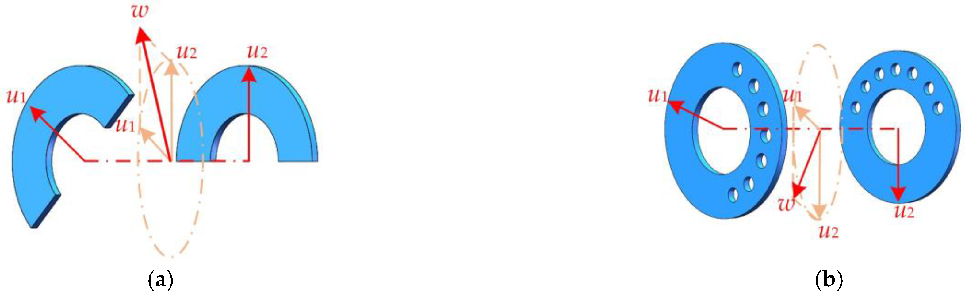
4.1. Principle

The motor-type automatic balancing actuator uses a micromotor and a transmission system to drive the counterweight plate to run, and finally reaches the target position to suppress vibration. The first motor-type automatic balancing device was proposed by Vande, which uses a small motor powered by a carbon brush slip ring to drive the counterweight block through the worm gear and worm [29,30]. Later, the Korean scholar Lee et al. used batteries to replace the carbon brush slip ring to power the motor, and realized the wireless control of the automatic balancing actuator [31]. At present, motor-type automatic balancing actuators represented by Italian Marposs and American SBS have been widely used in high-end grinders, but their existing structures cannot be used in aero-engines [32,33]. In addition, there are still the following three problems in motor-type automatic balancing actuators: (1) the carbon brush wear problem is faced in the process of signal transmission; (2) the transmission system of the actuator is the gear reduction mechanism such as worm gear and worm, and the installation space is large; (3) the actuator requires very high processing accuracy of internal precision parts such as gears and racks, resulting in very high costs. Aiming at the existing problems, this paper proposes a new type of an online automatic balancing actuator based on ultrasonic motor, which is introduced in the following.
The motor-type online automatic balance actuator presented in this paper used an ultrasonic motor as a power device. An ultrasonic motor can apply an AC voltage of ultrasonic frequency to the piezoelectric ceramic to excite the microvibration of the stator elastomer, making it rub against the rotor fixed with friction material. Finally, the micro-vibration is converted into the rotation of the motor rotor and output by using the common vibration frequency of the piezoelectric ceramic plate. Ultrasonic motors can change the standing wave vibration displacement of the stator plasmas by adjusting the excitation voltage frequency, thus achieving a stable regulation of the rotor speed of the motor [34]. Currently, it is widely used in medical devices, microelectromechanical systems, and aerospace fields. The ultrasonic motor has a simple structure, the response speed can reach the millisecond level, and it is not disturbed by external magnetic fields, so it has a good stability [35]. Therefore, an ultrasonic motor was introduced into the online automatic balance actuator so that the automatic balance system had a fast response and strong anti-interference ability. In terms of mechanical structure, the ultrasonic motor not only simplifies the complex transmission structure of worm-gear, but also makes the whole device lighter and smaller overall, making it more suitable for dual-rotor systems with limited installation space.
According to whether there is relative motion with the rotor to be balanced, the motor-type online automatic balance actuator is divided into two parts: a rotating ring and a fixed ring. The start and stop of the ultrasonic motor are controlled by infrared remote control. The power transmission path of the actuator is shown in Figure 9 (green line with arrows). After the ultrasonic motor runs, the torque is transmitted to the gear mechanism, and the counterweight part is driven to rotate through the planetary gear–ring gear, and the counterweight plates on the left and right planes can be independently controlled. The counterweight blocks in two different planes rotate in the circumferential direction, and the resultant vector generated by the two counterweight planes (adjusting the mass of the counterweight blocks or the angle between the two counterweight blocks) is used to offset the external unbalance of the system to achieve balance.

4.2. Structural Design

The automatic balance actuator is divided into two parts: the rotating ring and the fixed ring. The rotating ring consists of a gear component consisting of the planetary wheel–inner gear ring and a counterweight component, as shown in Figure 10. The gear component includes a planetary gear-ring gear. The counterweight component includes a counterweight block–counterweight disc. When the ultrasonic motor is started by infrared remote control, the counterweight component is driven to rotate through the meshing drive of the gear component, which makes the counterweight block reach the target position. Among them, a double-stop centering connection structure is designed between the rotating ring and the fixed ring on the end face of the inner gear ring and the counterweight disc, respectively, to ensure the stability of torque transmission. When the actuator is in operation, the balanced rotor is also rotating, so the bearing connection between the balanced rotor and the rotating ring is chosen. At the same time, the bearing also plays a supporting role in the counterweight components.
Based on the principle of the double-sided dynamic balance method, the balancing actuator has two disks on the left and right, corresponding to the space of two calibration fronts, respectively. The front of the calibration is perpendicular to the rotor axis, where the center of gravity of the counterweight is located. The eccentric mass can be formed in two ways: by adding weight and reducing weight. The counterweight block can be installed on the side of the counterweight plate, or the counterweight plate can be reduced in weight by punching a hole on one side of the counterweight plate, as shown in Figure 11. The vectors u 1 and u 2 are generated in the left and right discs, respectively, and the resulting vector w is synthesized to compensate for the unbalanced vector of the rotor being balanced.

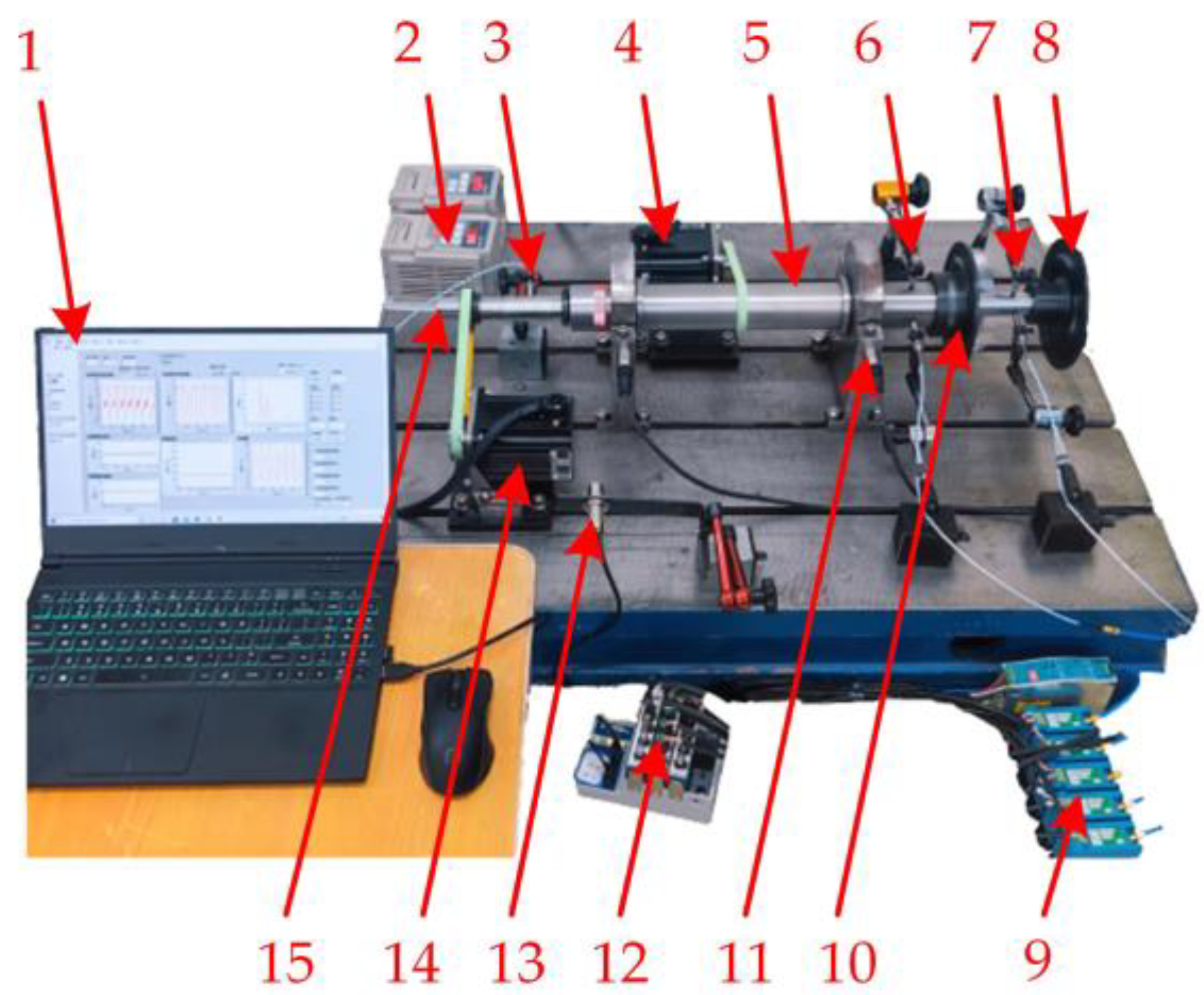
5. Experimental Verification

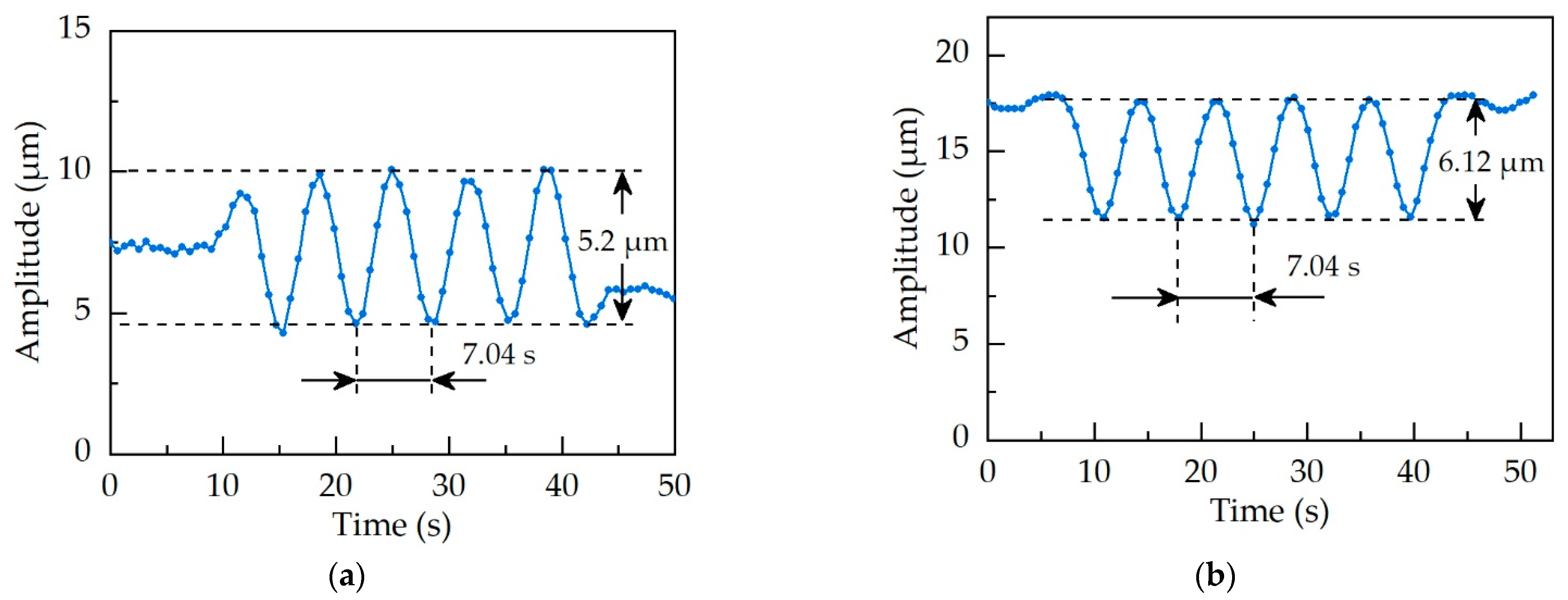
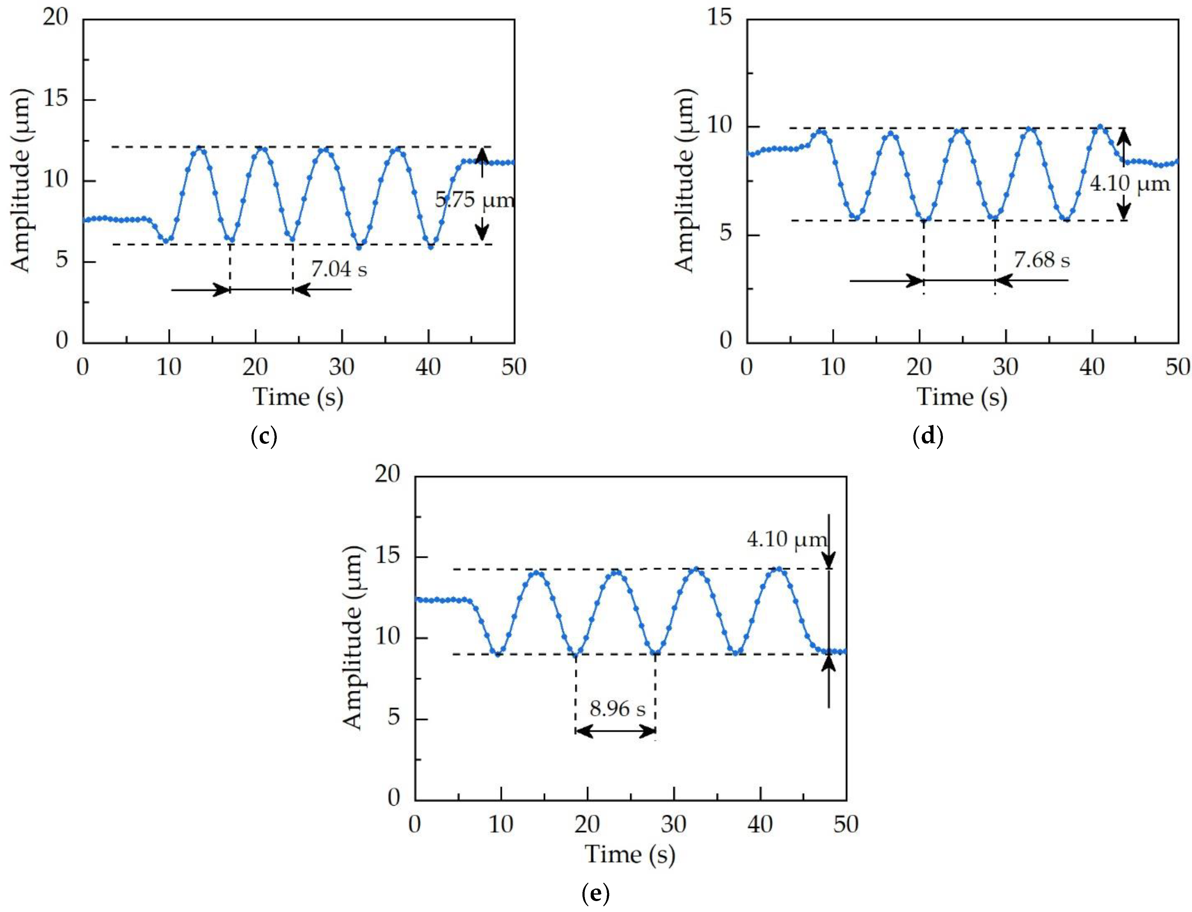
5.1. Unbalance Vibration Suppression Test Based on Self-Sensitivity Coefficient

Based on the structural characteristics of the dual-rotor system at the output of the open rotor engine, the dual-rotor test bench shown in Figure 12 was built. The test bench was mainly composed of a rotor-bearing system, motor, frequency converter, sensor, data acquisition, and computer. The rotor-bearing system was mainly composed of an inner rotor, outer rotor, bearings, and counterweight discs. The outer rotor was fixed to the base of the test bench through the bearing seat, and the inner rotor was supported on the inner wall of the outer rotor by two rolling bearings as intermediate bearings. The inner and outer rotors were driven by motors, and the motor speed and direction of rotation could be adjusted by the frequency converter. The sensors used for the test included eddy current sensors, photoelectric sensors, and acceleration sensors. The speed of the outer rotor was measured by the photoelectric sensor, and the speed of the inner rotor was measured by the eddy current sensor at the left end.
For the dual-rotor system composed of a high-pressure rotor and low-pressure rotor, the differential speed between the inner and outer rotors was relatively large. For the dual-rotor system at the output end of the open rotor engine and the coaxial output turboshaft engine, the rotational speed maintained a slight differential or the speed was the same. Therefore, vibration suppression experiments were carried out in this section according to the differential speeds of a high-pressure rotor and low-pressure rotor of real engines and the microdifferential conditions of the open rotor engine and the coaxial output turboshaft engine. For the differential speed condition, the speed ratio (n is used to represent the speed ratio) was selected as −1.5 and −1.2, respectively. To simulate the actual working condition, the speed ratio of the inner and outer rotors was chosen as −1.04 (that is, the speed difference was 60 r/min). In this paper, the vibration suppression under two speed ratios was carried out for different working conditions of the dual-rotor system. The two speed ratios were represented by n (outer rotor speed/inner rotor speed), where n was –1.5 and −1.2, respectively (“–” indicates the reverse rotation of the inner and outer rotors). The rotational speed of the outer rotor remained unchanged at 1500 r/min. Since the inner and outer rotors were unbalanced, the vibration suppression experiments were carried out based on the coupling vibration suppression strategy obtained by the simulation. That is, the inner rotor was balanced first, and then the outer rotor was balanced.
At each speed ratio, the unbalance mass added to the inner and outer rotors is shown in Table 3.

5.1.1. n = −1.5

The initial vibration of the inner and outer rotors at operating speed was measured, respectively, and the vibration of the inner rotor was measured after adding a test weight of 44.8 g ∠ 0° to the inner rotor. The counterweight of the inner rotor was calculated and added to the counterweight plate of the inner rotor. Then, a test weight of 44.9 g ∠ 45° was added to the outer rotor, and the vibration of the outer rotor after adding the test weight was measured. The counterweight to be added to the outer rotor was calculated and added to the outer rotor counterweight plate. Finally, the residual vibration of the inner and outer rotor was measured. The theoretical counterweights calculated and the actual counterweights added to the inner and outer rotors are shown in Table 4, and the initial and residual vibrations of the inner and outer rotors are shown in Figure 13a.

5.1.2. n = −1.2

The operating speed of the outer rotor was 1500 r/min, and the speed of the inner rotor was controlled at 1250 r/min. The vibration suppression test was carried out according to the vibration suppression test procedure with a speed ratio of −1.5. The initial vibration and residual vibration of the inner and outer rotors are shown in Figure 13b.

5.1.3. n = −1.04

The operating speed of the outer rotor was 1500 r/min, and the speed of the inner rotor was controlled at 1440 r/min. The vibration suppression test was carried out according to the vibration suppression test procedure with a speed ratio of −1.5. The initial vibration and residual vibration of the inner and outer rotors are shown in Figure 14.
It can be seen from the effect of the coupling vibration suppression in Figure 13 and Figure 14 that balancing the inner rotor first causes the vibration amplitude of the outer rotor to decrease synchronously. From the perspective of coupling vibration, when the speed ratio is −1.5, the inner rotor is balanced, and the vibration of the outer rotor is reduced by 26% synchronously. When the speed ratio is −1.2, the inner rotor is balanced, and the vibration of the outer rotor is simultaneously reduced by 7%. When the speed ratio is −1.04, the inner rotor is balanced, and the vibration of the outer rotor is simultaneously reduced by 3%. Therefore, balancing the inner rotor first to cause the vibration of the outer rotor to decrease synchronously is also desired positive feedback. From the final vibration suppression effect, the final reduction of the inner rotor vibration is 91%, and that of the outer rotor vibration is 81% for a speed ratio of −1.5. When the speed ratio is −1.2, the vibration of the inner rotor is finally reduced by 85%, and the vibration of the outer rotor is finally reduced by 90%. When the speed ratio is −1.04, the vibration of the inner rotor is finally reduced by 93%, and the vibration of the outer rotor is finally reduced by 84%. It can be seen that the coupling vibration suppression strategy obtained from the simulation is reasonable, and the vibration suppression effect is remarkable. In conclusion, the experimental results illustrated the following phenomena: (1) balancing the inner rotor can synchronously reduce the vibration of the outer rotor; (2) the step-by-step vibration suppression strategy of balancing the inner rotor first and then balancing the outer rotor can achieve the final vibration suppression effect. According to the above two phenomena, a dual-actuator step-by-step automatic balancing strategy can be formed to suppress the unbalanced vibration of the dual-rotor system, as shown in Figure 15. That is, when there is an unbalanced fault in the rotor system, the automatic balancing actuator will run in sequence according to the specific situation, thereby the unbalanced fault is eliminated.

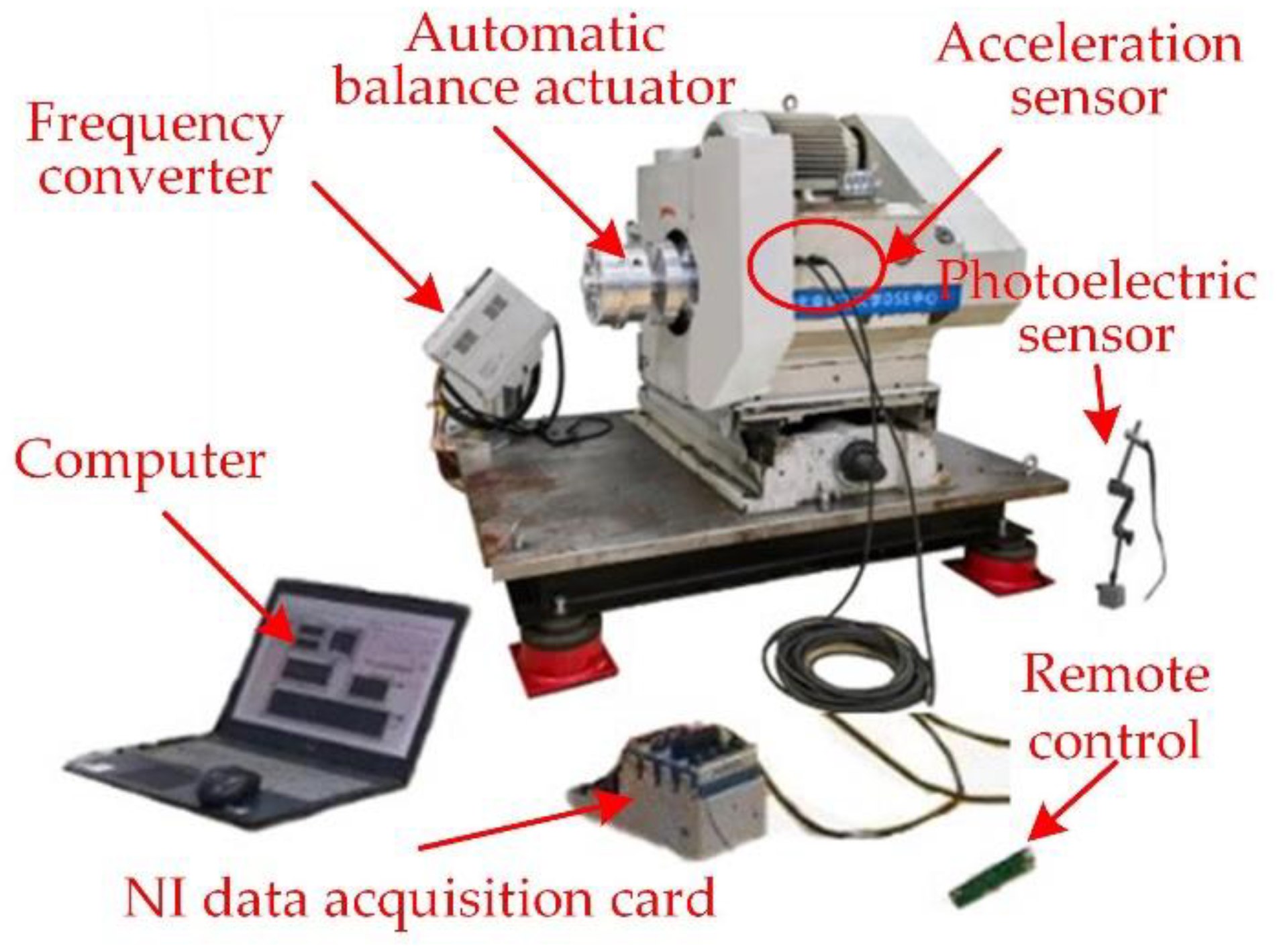
5.2. Feasibility Test Verification of the Balancing Actuator

We completed the assembly and static test of the balancing actuator by machining, assembling, and testing the relevant parts. The balancing actuator was a circular structure that could be installed through the shaft, with an overall diameter of 160 mm and an axial length of no more than 110 mm, and the designed balancing capacity could reach 3400 gmm.
In order to verify the feasibility and effectiveness of the online automatic balance actuator, the spindle of a test bench was used as the rotor to be balanced, and the balancing actuator was installed to one end of the spindle through the connecting flange with a dummy shaft, as shown in Figure 16. The acceleration sensor was fixed to the bearing seat of the test bench by the magnetic suction base, and the vibration signal was collected in real time by the acceleration sensor. The vibration signal was subjected to a fast Fourier transformation through LabVIEW, and the displacement amplitude of the spindle was obtained by quadratic integration.
Due to the limitation of the vibration condition of the spindle rotor itself, the speed of this test did not exceed 1200 r/min. In the experiments, the frequency converter was adjusted to change the speed of the rotor being balanced. At the speeds of 400 r/min, 800 r/min, 900 r/min, 1000 r/min, and 1100 r/min, the ultrasonic motor was controlled by the infrared remote controller to start and drive the counterweight to rotate. The amplitude curve of spindle vibration of the fundamental frequency was obtained, as shown in Figure 17.
It can be seen from the amplitude curve of the spindle vibration at 1X frequency under five different rotation speeds in Figure 17 that the amplitude of the rotor vibration changes in a sinusoidal pattern under the actuator working without a break. It indicates that the actuator can achieve automatic balance. In addition, the vibration of the balanced rotor can be reduced by more than 34% in 5 s under different test speeds by using the balancing actuator, which is more substantial evidence that the actuator has a fast response speed. The fast response speed is also the most significant advantage of the actuator proposed in this paper. Therefore, the feasibility test results show that the actuator is capable of automatic balance.

6. Conclusions

In this paper, the typical cantilever coaxial dual-rotor system at the output end of an open engine and a coaxial output turboshaft engine was analyzed, and a coaxial counter-rotating dual-rotor test bench with a similar structure was designed. The dynamic characteristic analysis and unbalance vibration suppression experiment of the designed dual-rotor structure were carried out. Then, an automatic balance actuator applicable to the dual-rotor structure was designed, and feasibility experiments were completed. The main conclusions drawn in this paper are as follows:
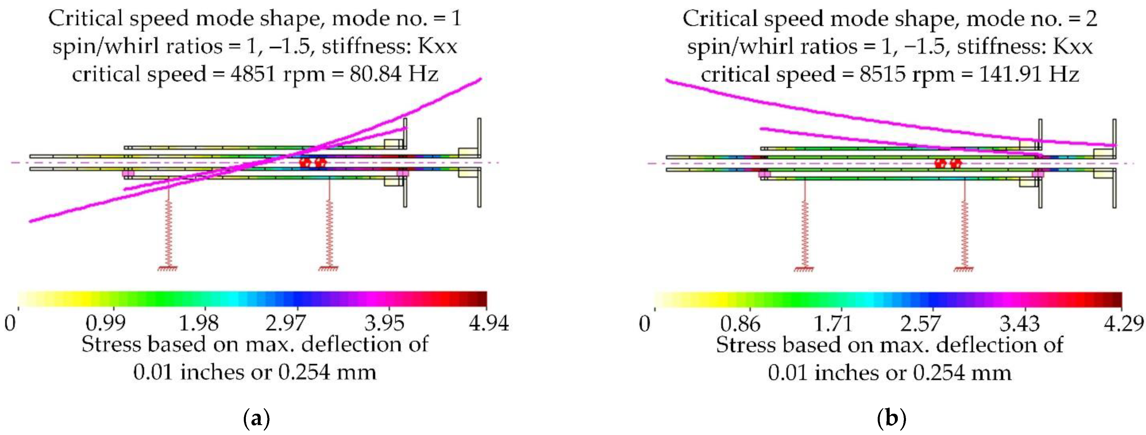
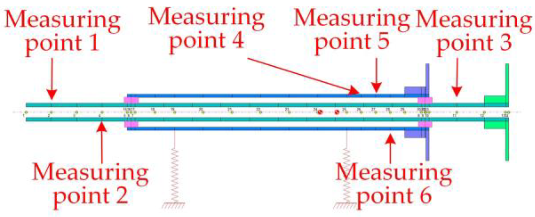
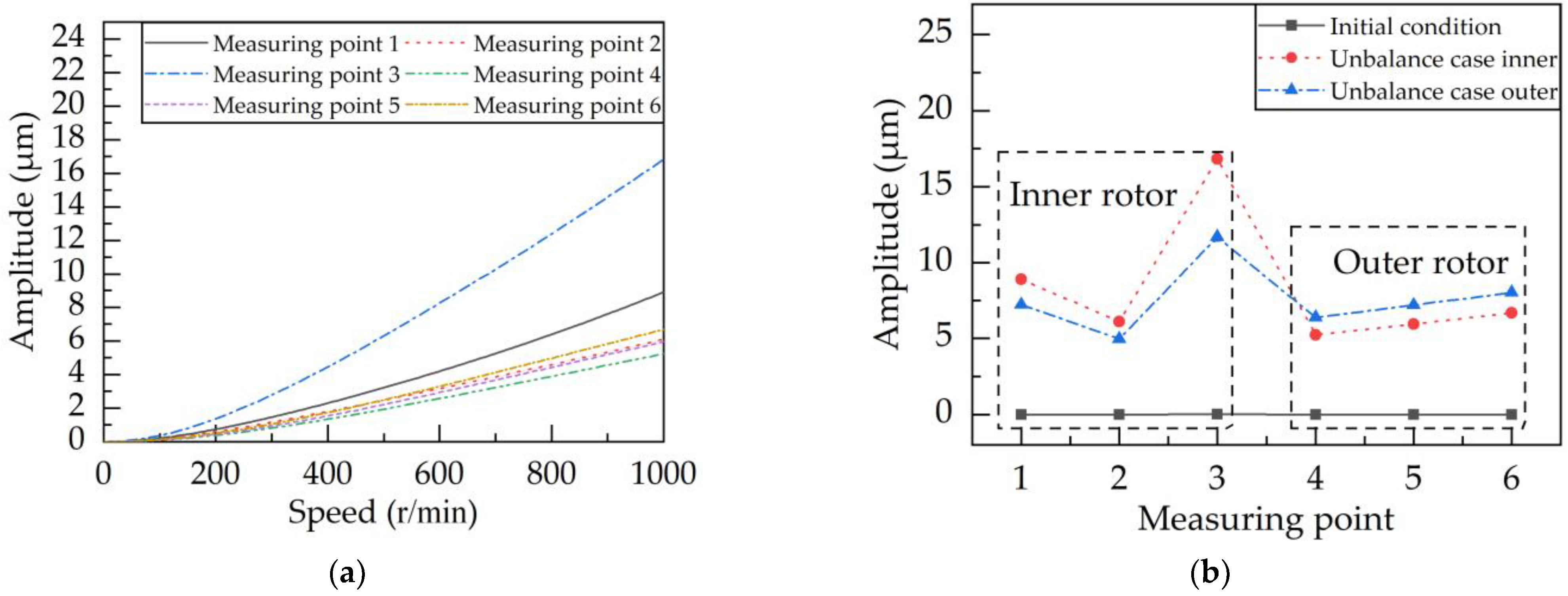
  • The unbalance response analysis of the dual-rotor system under the condition of a –1.5 speed ratio was carried out by DyRoBeS software. The results showed that the law of vibration transmission on the rotor system applied: for rigid rotors, the closer to the vibration source, the more sensitive the vibration, that is, the more suitable for the layout of vibration measurement points;
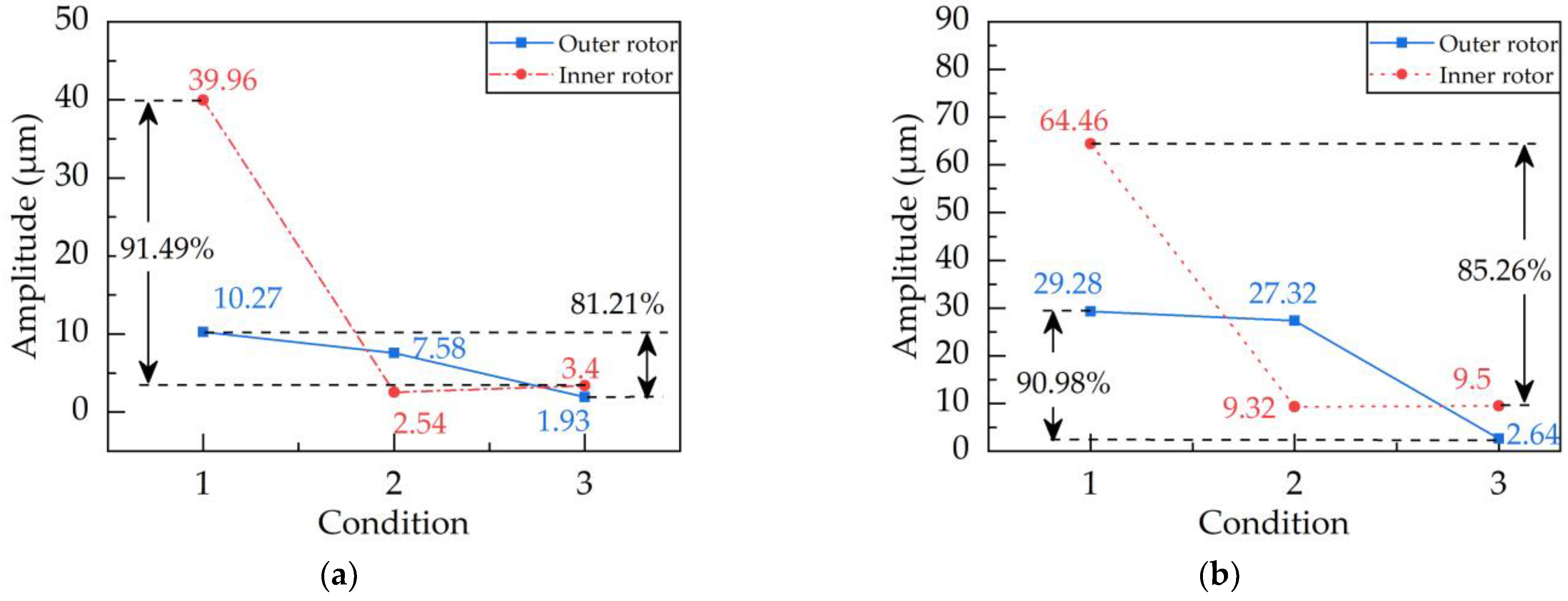
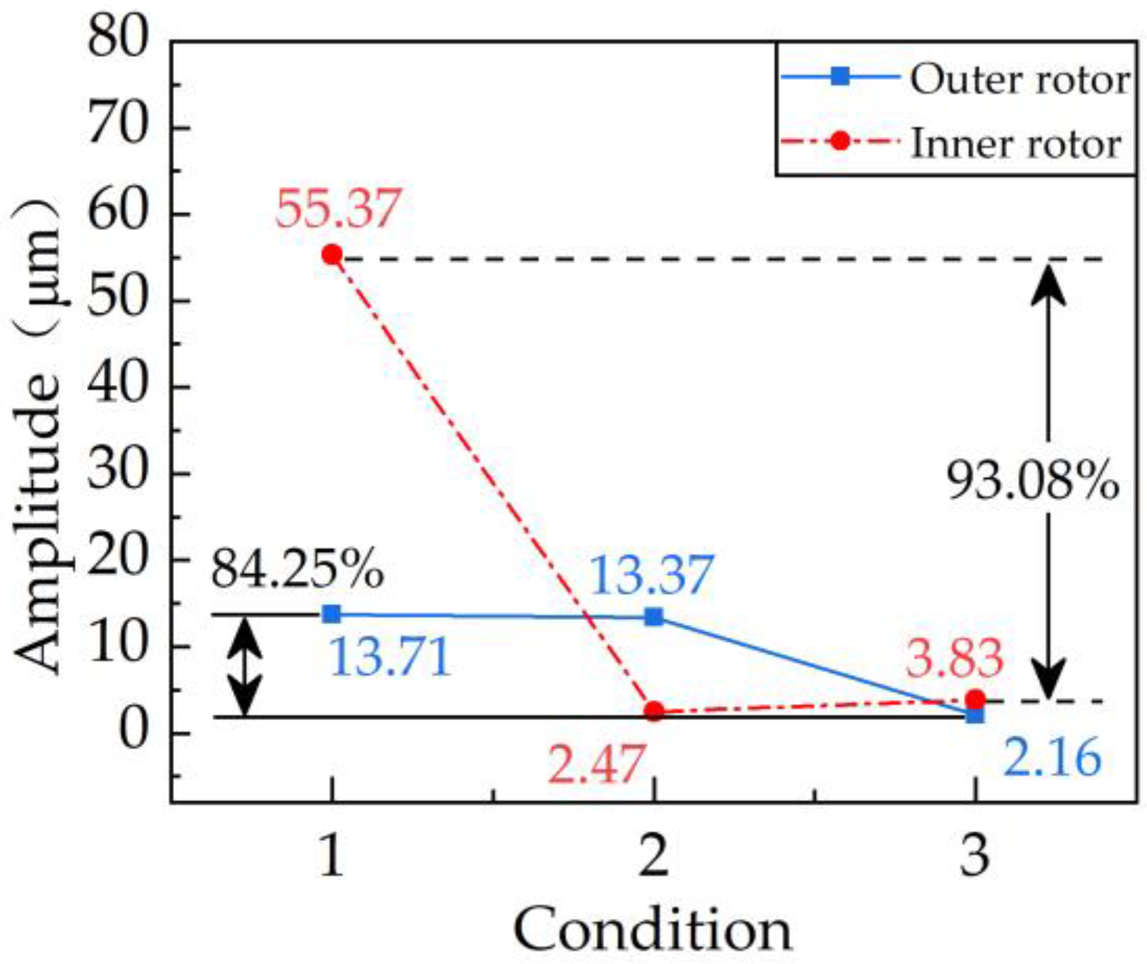
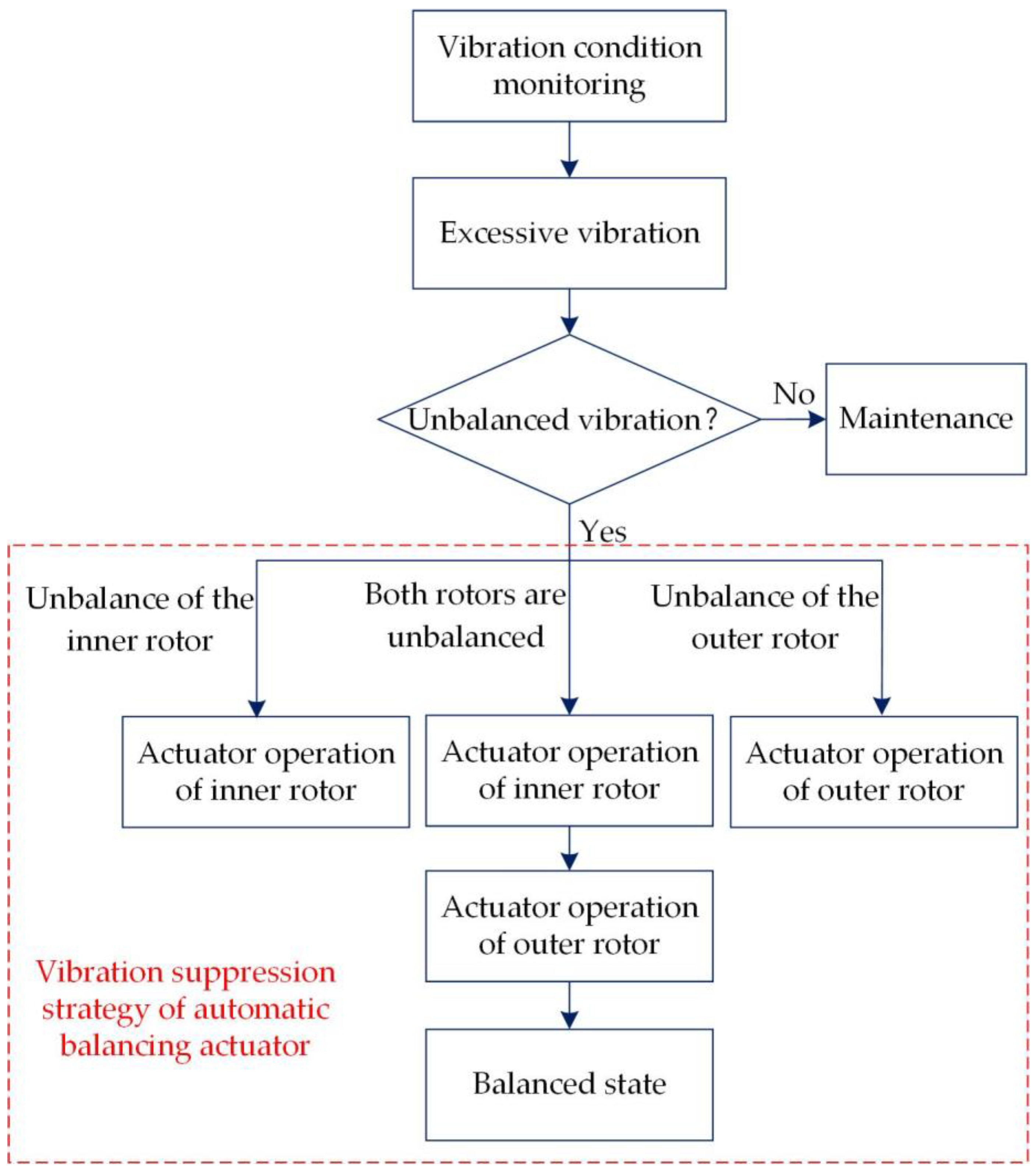
  • Based on the unbalance response analysis, the concept of self-sensitivity coefficient was established to describe the sensitivity of the measurement point to the vibration caused by the structure where the measurement point is located. The experimental results of unbalanced vibration suppression under three operating conditions of −1.5, −1.2, and −1.04 speed ratios showed that the self-sensitivity coefficient could be used as a theoretical basis for the actual vibration measurement point arrangement and unbalanced vibration suppression strategy of the dual-rotor system.
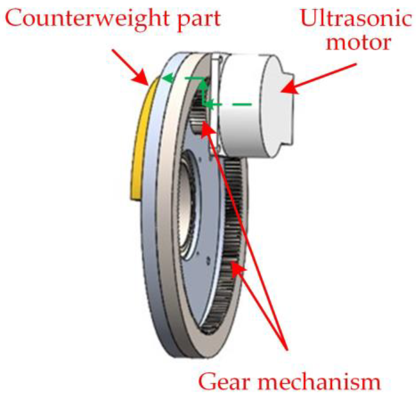
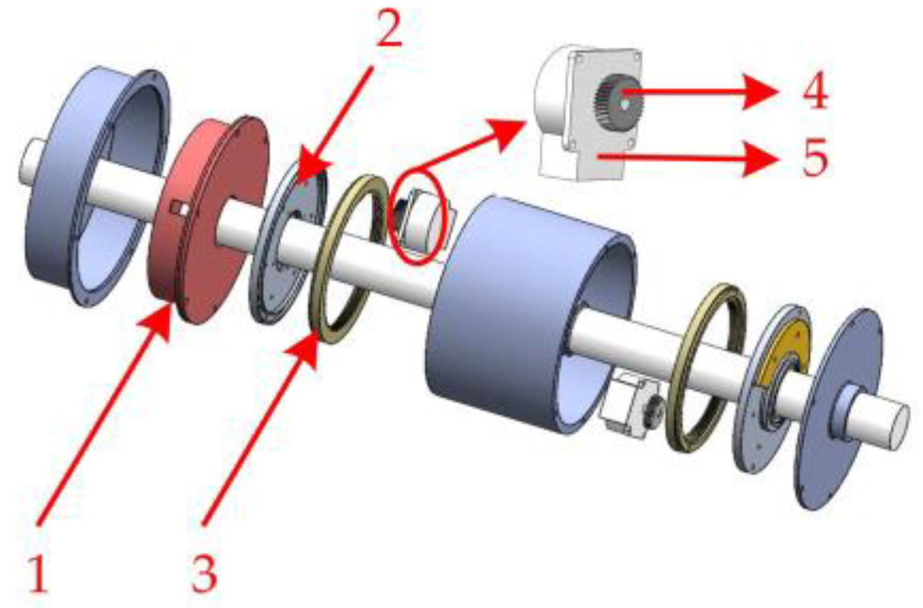
  • An automatic balance actuator suitable for a dual-rotor structure at the output end of open rotor engines and coaxial output turboshaft engines was designed and analyzed on a rotor test bench for feasibility. The results showed that the vibration of the balanced rotor could be reduced by more than 34% in 5 s under different test speeds by using the balancing actuator. It was further demonstrated that the actuator had a fast response, satisfying self-locking requirements, and a stable operation. Ultimately, the actuator could quickly suppress the vibration within the range of balance capability.
In subsequent research, the influence of large propeller blades in the real structure and actual differential speed conditions on the dynamic characteristics and vibration suppression of the dual-rotor system will be further considered. Then, the structure of the balancing actuator will continue to be improved. Finally, the multiactuator online control strategy applicable to the dual-rotor system will be studied to provide technical support for the engineering application of this technology.

Author Contributions

Conceptualization, J.L. and X.P.; methodology, J.L.; software, J.L.; validation, J.L., X.Z., M.Z., and X.P.; formal analysis, X.P.; investigation, J.L.; resources, X.P.; data curation, J.L.; writing—original draft preparation, J.L.; writing—review and editing, X.Z.; visualization, X.P.; supervision, X.P.; project administration, X.P.; funding acquisition, X.P. All authors have read and agreed to the published version of the manuscript.

Funding

This research was funded by National Natural Science Foundation of China (grant no. 51875031) and Beijing Natural Science Foundation (grant no. 3212010).

Institutional Review Board Statement

Not applicable.

Informed Consent Statement

Not applicable.

Data Availability Statement

Not applicable.

Acknowledgments

The authors sincerely thank the National Natural Science Foundation of China (NSFC) and Beijing Natural Science Foundation for funding and Beijing University of Chemical Technology (BUCT) for providing us with a good platform.

Conflicts of Interest

The authors declare no conflict of interest.

References

  1. Li, L.; Cao, S.; Li, J.; Nie, R.; Hou, L. Review of Rotor Balancing Methods. Machines 2021, 9, 89. [Google Scholar] [CrossRef]
  2. Pan, X.; Lu, J.Q.; Huo, J.J.; Gao, J.J.; Wu, H.Q. A Review on Self-Recovery Regulation (SR) Technique for Unbalance Vibration of High-End Equipment. Chin. J. Mech. Eng. 2020, 33, 89. [Google Scholar] [CrossRef]
  3. Wang, N.F.; Jiang, D.X. Vibration response characteristics of a dual-rotor with unbalance-misalignment coupling faults: Theoretical analysis and experimental study. Mech. Mach. Theory 2018, 125, 207–219. [Google Scholar] [CrossRef]
  4. Ma, P.; Zhai, J.; Wang, Z.; Zhang, H.; Han, Q.K. Unbalance Vibration Characteristics and Sensitivity Analysis of the Dual-Rotor System in Aeroengines. J. Aerospace Eng. 2021, 34, 04020094. [Google Scholar] [CrossRef]
  5. Ma, Y.; Shi, C.; Sun, B.; Hong, J. Method of Coupled Vibration Control for Dual Rotor System With Inter-Shaft Bearing. In Proceedings of the ASME Turbo Expo 2021: Turbomachinery Technical Conference and Exposition, 7–11 June 2021. [Google Scholar]
  6. Ma, X.; Ma, H.; Qin, H.; Guo, X.; Zhao, C.; Yu, M. Nonlinear vibration response characteristics of a dual-rotor-bearing system with squeeze film damper. Chin. J. Aeronaut. 2021, 34, 128–147. [Google Scholar] [CrossRef]
  7. Lu, Z.Y.; Wang, X.D.; Hou, L.; Chen, Y.S.; Liu, X.Y. Nonlinear response analysis for an aero engine dual-rotor system coupled by the inter-shaft bearing. Arch. Appl. Mech. 2019, 89, 1275–1288. [Google Scholar] [CrossRef]
  8. Lu, Z.Y.; Zhong, S.; Chen, H.Z.; Wang, X.D.; Han, J.J.; Wang, C. Nonlinear response analysis for a dual-rotor system supported by ball bearing. Int. J. Non-Linear Mech. 2021, 128, 103627. [Google Scholar] [CrossRef]
  9. Han, J.; Luo, G.; Chen, W.; Wang, F.; Liu, L.; Zhao, Z.; Luo, G. Coupling Vibration Analysis of Turbine Shared Support Rotor-Bearing System with Squeeze Film Dampers. Int. J. Aerosp. Eng. 2022, 2022, 8425735. [Google Scholar] [CrossRef]
  10. Ibn Shamsah, S.M.; Sinha, J.K. Rotor Unbalance Estimation with Reduced Number of Sensors. Machines 2016, 4, 19. [Google Scholar] [CrossRef]
  11. Chen, Y.; Cui, J.; Sun, X. A Vibration Suppression Method for the Multistage Rotor of an Aero-Engine Based on Assembly Optimization. Machines 2021, 9, 189. [Google Scholar] [CrossRef]
  12. Ponci, L.P.; Creci, G.; Menezes, J.C. Simplified procedure for vibration analysis and dynamic balancing in mechanical systems with beats frequency. Measurement 2021, 174, 109056. [Google Scholar] [CrossRef]
  13. Zhang, Z.X.; Wang, L.Z.; Jin, Z.J.; Zhang, Q.; Li, X.L. Non-whole beat correlation method for the identification of an unbalance response of a dual-rotor system with a slight rotating speed difference. Mech. Syst. Signal Process. 2013, 39, 452–460. [Google Scholar] [CrossRef]
  14. Zhang, Z.X.; Zhang, Q.; Li, X.L.; Qian, T.L. The whole-beat correlation method for the identification of an unbalance response of a dual-rotor system with a slight rotating speed difference. Mech. Syst. Signal Process. 2011, 25, 1667–1673. [Google Scholar] [CrossRef]
  15. Fang, J.; Xu, X.; Xie, J. Active vibration control of rotor imbalance in active magnetic bearing systems. J. Vib. Control. 2013, 21, 684–700. [Google Scholar] [CrossRef]
  16. Gong, L.; Zhu, C. Synchronous Vibration Control for Magnetically Suspended Rotor System Using a Variable Angle Compensation Algorithm. IEEE Trans. Ind. Electron. 2021, 68, 6547–6559. [Google Scholar] [CrossRef]
  17. Fan, H.W.; Jing, M.Q.; Wang, R.C.; Liu, H.; Zhi, J.J. New electromagnetic ring balancer for active imbalance compensation of rotating machinery. J. Sound Vib. 2014, 333, 3837–3858. [Google Scholar] [CrossRef]
  18. Pan, X.; He, X.; Wu, H.; Ju, C.; Jiang, Z.; Gao, J. Optimal Design of Novel Electromagnetic-Ring Active Balancing Actuator with Radial Excitation. Chin. J. Mech. Eng. 2021, 34, 9. [Google Scholar] [CrossRef]
  19. Pan, X.; Xie, Z.; Lu, J.; Wu, H.; Gao, J.; Jiang, Z. Novel Liquid Transfer Active Balancing System for Hollow Rotors of High-Speed Rotating Machinery. Appl. Sci. 2019, 9, 833. [Google Scholar] [CrossRef]
  20. Zhang, X.; Liu, X.; Zhao, H. New Active Online Balancing Method for Grinding Wheel Using Liquid Injection and Free Dripping. J. Vib. Acoust.-Trans. ASME 2018, 140. [Google Scholar] [CrossRef]
  21. EQuiroz-Hernandez, E. Method for Balancing a Propulsive System Having Non-Hull Contral-Rotating Propellers. US 8998580 B2, 7 April 2015. [Google Scholar]
  22. Augustin Curlier, T.B.; Gilles Alain Charier. Epicyclic Reduction Gear with Fluid Transfer Pipes, and Propeller Turbomachine for an Aircraft with Such a Reduction Gear. US 10006539 B2, 26 June 2018. [Google Scholar]
  23. Pope, A.N. Thrust Force-Compensating Apparatus with Improved Hydraulic Pressure-Responsive Balance Mechanism. US 5102295 A, 7 April 1992. [Google Scholar]
  24. Richard, G.; Stretton, N.H. Propfan Engine. US 8967967 B2, 3 March 2015. [Google Scholar]
  25. Alekseevich, K.V. Gas Turbine Engine With Double-Row Propeller Fan. RU2428577C1, 10 September 2011. [Google Scholar]
  26. Chen, W.J. Introduction to Dynamics of Rotor-Bearing Systems; Trafford Publishing: Bloomington, IN, USA, 2007. [Google Scholar]
  27. Vance, J.; Zeidan, F.; Murphy, B. Machinery Vibration and Rotordynamics; John Wiley & Sons, Inc.: Hoboken, NJ, USA, 2010. [Google Scholar]
  28. Chen, X.; Liao, M. Steady-State Characteristics of a Dual-Rotor System With Intershaft Bearing Subjected to Mass Unbalance and Base Motions. In Proceedings of the ASME Turbo Expo 2018: Turbomachinery Technical Conference and Exposition, Oslo, Norway, 11–15 June 2018. [Google Scholar]
  29. Vande Vegte, J. Continuous Automatic Balancing of Rotating Systems. J. Mech. Eng. Sci. 1964, 6, 264–269. [Google Scholar] [CrossRef]
  30. Van de Vegte, J.; Lake, R.T. Balancing of rotating systems during operation. J. Sound Vib. 1978, 57, 225–235. [Google Scholar] [CrossRef]
  31. Kim, Y.D.; Lee, C.W. Determination of the Optimal Balancing Head Location on Flexible Rotors Using a structural Dynamics Modification Algorithm. Proc. Inst. Mech. Eng. Part C J. Mech. Eng. Sci. 1985, 199, 19–25. [Google Scholar] [CrossRef]
  32. Marposs. Flange and Spindle Type Balancing Heads Guiding Line. Available online: https://www.marposs.com/chi/product/flange-and-spindle-type-balancing-heads (accessed on 5 August 2022).
  33. Schmitt. Operation and Specification Manual for the SBS Dynamic Balance System: Model 4500 Series Control Unit. Available online: https://accretechsbs.com/product/1-external-balancers/ (accessed on 5 August 2022).
  34. Li, C.; Lu, C.; Ma, Y.; Li, S.; Huang, W. Design of an ultrasonic motor with multi-vibrators. J. Zhejiang Univ.-Sci. A 2016, 17, 724–732. [Google Scholar] [CrossRef]
  35. Li, X.; Wen, Z.; Jia, B.; Cao, T.; Yu, D.; Wu, D. A Review of Application and Development Trends in Ultrasonic Motors. ES Mater. Manuf. 2021, 12, 3–16. [Google Scholar] [CrossRef]
Figure 1. The coaxial counter-rotating dual-rotor structure at the output end of an open-rotor engine.
Machines 10 00758 g001
Figure 2. The cantilevered coaxial dual-rotor automatic balance system.
Machines 10 00758 g002
Figure 3. Equivalent dynamics model of coaxial counter-rotating dual-rotor system.
Machines 10 00758 g003
Figure 4. The cantilever dual-rotor test bench.
Machines 10 00758 g004
Figure 5. Finite element model.
Machines 10 00758 g005
Figure 6. The mode shape. (a) The first-order mode shape; (b) the second-order mode shape.
Machines 10 00758 g006
Figure 7. Measuring points of simulation.
Machines 10 00758 g007
Figure 8. The steady-state response. (a) The unbalance is on the inner rotor; (b) unbalanced vibration response of all measuring points.
Machines 10 00758 g008
Figure 9. The power transmission path of the actuator.
Machines 10 00758 g009
Figure 10. Explosion diagram of automatic balance actuator: 1. control module; 2. counterweight component; 3. ring gear; 4. planetary gear; 5. ultrasonic motor.
Machines 10 00758 g010
Figure 11. Schematic diagram of eccentric mass. (a) Adding weight; (b) reducing weight.
Machines 10 00758 g011
Figure 12. Dual-rotor test bench: 1. computer; 2. frequency converter; 3. eddy current sensor; 4. motor of the inner rotor; 5. outer rotor; 6. eddy current sensor; 7. eddy current sensor; 8. counterweight discs; 9. front end circuit; 10. counterweight discs; 11. acceleration sensor; 12. NI; 13. photoelectric sensor; 14. motor of the outer rotor; 15. inner rotor.
Machines 10 00758 g012
Figure 13. Coupled vibration suppression effect under differential speed. (a) n = −1.5; (b) n = −1.2. The horizontal coordinate 1 represents the initial state, the horizontal coordinate 2 represents the dynamic balance of the inner rotor, and 3 represents the dynamic balance of the outer rotor.
Machines 10 00758 g013
Figure 14. Vibration suppression effect under the condition of slight differential speed. The horizontal coordinate 1 represents the initial state, the horizontal coordinate 2 represents the dynamic balance of the inner rotor, and 3 represents the dynamic balance of the outer rotor.
Machines 10 00758 g014
Figure 15. Vibration suppression strategy.
Machines 10 00758 g015
Figure 16. Overall structure drawing of the test device.
Machines 10 00758 g016
Figure 17. The amplitude curve of spindle vibration of 1X frequency. (a) Rotation speed of 350 r/min; (b) rotation speed of 800 r/min; (c) rotation speed of 900 r/min; (d) rotation speed of 1000 r/min; (e) rotation speed of 1100 r/min.
Machines 10 00758 g017aMachines 10 00758 g017b
Table 1. Response of each measuring point.
Measuring PointAmplitude/μm
Initial ConditionUnbalance Case InnerUnbalance Case Outer
10.0038.9027.231
20.0026.1004.956
30.00616.82411.708
40.0025.2356.371
50.0035.9517.192
60.0036.6848.049
Table 2. Response of each measuring point.
Measuring PointSelf-Sensitivity Coefficient
Inner rotor155.2%
255.2%
359.0%
Outer rotor454.9%
554.7%
654.6%
Table 3. The unbalance mass of inner and outer rotors at each speed ratio.
RotorThe Unbalance Mass/g
n = −1.5n = −1.2n = −1.04
Inner rotor44.94554.6
Outer rotor45.289.654.8
Table 4. The theoretical counterweights and the actual counterweights.
RotorTheoretical Counterweight
/g°
Actual Counterweight
/g°
Inner rotor22.39 ∠ 75.864.0 ∠ 0 + 20.4 ∠ 90
Outer rotor43.72 ∠ 96.9743.4 ∠ 90 + 5.3 ∠ 180
Publisher’s Note: MDPI stays neutral with regard to jurisdictional claims in published maps and institutional affiliations.

