Article

Meshing Characteristics of Spur Gears Considering Three-Dimensional Fractal Rough Surface under Elastohydrodynamic Lubrication

1
School of Mechanical Engineering and Automation, Northeastern University, Shenyang 110819, China
2
China North Vehicle Research Institute, Beijing 100072, China
3
Key Laboratory of Vibration and Control of Aero-Propulsion Systems Ministry of Education of China, Northeastern University, Shenyang 110819, China
4
AVIC Shenyang Engine Design Institute, Shenyang 110015, China
5
National Key Laboratory of Science and Technology on Helicopter Transmission, Nanjing University of Aeronautics and Astronautics, Nanjing 210016, China
*
Author to whom correspondence should be addressed.
Machines 2022, 10(8), 705; https://doi.org/10.3390/machines10080705
Submission received: 8 July 2022 / Revised: 13 August 2022 / Accepted: 15 August 2022 / Published: 17 August 2022
(This article belongs to the Section Friction and Tribology)

Abstract

:
Taking the effect of actual surface topography under elastohydrodynamic lubrication (EHL) conditions on the contact state of gear pairs into consideration, a combination model with the analytical sliced method and two-dimensional (2D) EHL model is proposed to characterize the three-dimensional (3D) meshing characteristics of spur gears. Firstly, the surface topology of gears is tested by a surface profiler, which reflects that the topography of tooth surface accords with fractal characteristics. Thus, by adopting the Weierstrass–Mandelbrot (W-M) fractal function, the gear surface is characterized. Secondly, the numerical 2D EHL model with fractal roughness is established, and distributions of oil film pressure (OFP) and oil film thickness (OFT) at different meshing positions are obtained. Finally, considering the different topography distributions in the direction of face width, time-varying mesh stiffness (TVMS) is calculated based on the analytical sliced method. Thus, the influence of 3D surface topography can be considered. The Hertz contact stiffness is substituted by the time-varying lubricating oil film stiffness (OFS). The influences of tooth surface topography and lubricant film characteristics on meshing characteristics are investigated. The results show that the 3D rough tooth surface may be well characterized by a fractal function with random phase. Moreover, there is a great difference in the distribution of OFP and OFT between rough and smooth surfaces, which certainly influences the gear meshing characteristics.

1. Introduction

The meshing and lubrication characteristics are important factors influencing the service life and working performance of gear pairs widely used in aero engines and vehicle drivetrains. The microstructure of gear interfaces may be different with different machining methods [1], which affects the lubrication condition and contact state. Therefore, it is of great importance to investigate gear meshing characteristics with rough surfaces under elastohydrodynamic lubrication (EHL) conditions. The calculation model of time-varying mesh stiffness (TVMS) is also being improved to take into account actual situations more comprehensively. The analytic finite element method [2,3,4] and analytical method [5,6,7] are most widely adopted to calculate TVMS because of their high efficiency and accuracy. It is worth mentioning that the slice theory [5,6] is applied to the analytical method to consider the influence of tooth profile deviation. For all these models, the gear contact stiffness is obtained by Hertz contact theory. The Hertzian contact theory, on the other hand, applies only to static contact between a pair of smooth surfaces, without consideration of lubrication, which is greatly different from the actual situation of gear transmission. In fact, almost all gears work with lubrication. In addition, the pressure fluctuation caused by asperities will lead to the dynamic change in lubricant conditions (including oil film thickness and pressure distribution), which further leads to the fluctuation of contact stiffness between gear surfaces. Actually, many scholars have discussed the influence of tooth topography and EHL on contact state of gears. In the following text, the research status of rough surface characterization and EHL solution will be introduced emphatically.
Lots of studies on gear lubrication have been conducted both experimentally and theoretically, including the effects of lubrication on gear power loss, friction condition, contact fatigue characteristics, and dynamic characteristics. The lubrication performance parameters, surface roughness topography, and temperature effect are taken into account [8,9,10,11]. Zhu et al. [12,13,14] have carried out a series of research works on the EHL problem, which provides a full numerical method for solving the EHL model. The two-dimensional (2D) adhesive wear prediction model combining the load-sharing concept and thermal elastohydrodynamic lubrication (TEHL) analysis of rough surfaces was proposed to predict the steady state adhesive wear in gears [15]. A 2D transient, non-Newtonian, mixed EHL model of spur gear tooth contact was proposed by Li and Kahraman [16]. When the asperities come into contact, the oil film breaks, and the load is shared by the asperities and oil film. In this state, a reduced form of the Reynolds equation was applied. Later, Li and Kahraman [17] further proposed a model to predict load-dependent power losses by using a transient EHL model. This model was applied to the 2D spur gear. Similar to Ref. [16], the reduced Reynolds equation was solved. Elisaus et al. [18] focused on the kinematics and contact microgeometry of spur gears with profile and lead modifications, but the proposed model did not involve the calculation of the time-varying mesh stiffness (TVMS) of the gears. In Ref. [19], a 2D comprehensive approach was proposed based on the established TEHL analysis model, and the lubricated loaded tooth contact analysis (LLTCA) of spur gears was conducted. The calculation of the TVMS of gears was not involved. Ren et al. [20] put forward a model for solving the line contact mixed EHL. The mating of two gears is equivalent to a line contact process with varying parameters, and the gear contact stiffness considering the real rough surface can be obtained. On this basis, Shi et al. [21,22] studied the EHL characteristics of gears considering three-dimensional (3D) surface topography, and explored the friction and flash temperature under lubrication conditions. Liu et al. [23,24,25,26,27] also conducted a lot of research on gear lubrication. They further considered the effects of dynamic load, tooth surface material properties on gear lubrication, and evolution of pitting and crack failure under lubrication contact. Jian et al. [28] investigated the effect of modification coefficient on lubrication characteristics under dynamic load. TVMSs with and without considering oil film stiffness (OFS) were calculated, however, the surface roughness was not considered. Yin et al. [29] investigated the influence of gear topography on friction force and damping under dynamic load considering mixed EHL contact. However, the calculation of TVMS did not take the OFS and tooth surface topography into consideration.
Recently, many studies have been carried out to study the contact model of gear pairs under different lubrication conditions. Xiao et al. [30] and Sun et al. [31] established contact models considering asperity and lubricating contact stiffness under mixed lubrication conditions, and the results show that surface topography and lubrication characteristics have great influences on contact stiffness. Zhou et al. [32] obtained gear contact stiffness with different working conditions considering lubrication, but the rough surface was not included in the discussion. Cheng et al. [33,34] calculated the contact stiffness of rough tooth surfaces considering lubrication. The distributions of oil film pressure (OFP) and oil film thickness (OFT) in the meshing contact region at different times are calculated, and the contact stiffness and TVMS were calculated under different working conditions. Wang and Zhu [35] calculated the TVMS of helical gears considering friction, in which the friction coefficient is related to lubrication parameters and roughness. Wang et al. [36] established a dynamic model to evaluate the power loss of a planetary gear system under EHL conditions involving surface roughness. The effects of roughness on friction coefficient and distributions of OFP and OFT were also exhibited. Huang et al. [37] introduced the fractal-based surface roughness into the EHL friction coefficient to investigate the influence of roughness on system dynamic characteristics. In their models, the effect of surface topography on TVMS was not discussed. Other studies focus on the interaction between lubrication and gear failures. Through experiment and simulation, Wei et al. [38] explored the surface stress distribution under rough lubrication, and the formation mechanism of tooth surface pitting fault under the action of this stress was investigated. Huangfu et al. [39] established a hybrid tribo-dynamic model, and a pitting fault evolution process was simulated. The 3D tooth surface topography was characterized by a W-M fractal function and the 3D mixed EHL model was solved to obtain the friction coefficient and OFS. Wang et al. [40] investigated the effect of spalling on lubrication, meshing, and dynamic characteristics, but surface roughness was set to be zero.
To sum up, the EHL state is the normal working state of the gear, which has an impact on the contact characteristics. At present, two-dimensional (2D) and 3D models are mostly used to simultaneously consider the influence of surface topography and lubrication on meshing characteristics of gear pairs. However, when considering surface topography, a 2D model only involves the roughness along the tooth profile and ignores the topography difference of the tooth surface along the face width direction, which cannot fully reflect the effect of the real tooth surface topography on lubrication and meshing characteristics. Although the 3D rough surface is considered in the 3D model, it is inevitable to solve the 3D EHL model, which is complex and time-consuming. Therefore, it may be necessary to make a tradeoff between the involvement of 3D tooth surface topography and the complexity of solving the 3D EHL model. On this basis, the aim of this paper is to propose an analytical model for investigating the meshing characteristics of spur gears under EHL conditions, which can take into consideration the influence of 3D surface topography without solving the 3D EHL model.
In this study, a revised model for calculating TVMS considering 3D surface topography under EHL conditions is established. The topography of the gear tooth surface is characterized by adopting fractal theory (Section 2). The OFS (also regarded as contact stiffness in this paper) considering fractal roughness is calculated by solving the 2D EHL model based on a multi-grid method (Section 3). The EHL model of each gear slice along the face width direction is solved based on the slice theory. In this way, the solution of the complex 3D EHL model can be avoided while considering the 3D tooth surface topography. The TVMS is calculated by the analytical sliced method considering 3D rough topography, and numerical examples are given to study the effect of different impact factors (Section 4).

2. Characterization of Gear Surface Topography

The 3D tooth surface topography is obtained by measurement, which is the basis for the accurate characterization of the gear tooth surface. In this section, surface topography of the gear specimen is measured by a 3D profiler, and on the basis of finding that it has fractal characteristics, the Weierstrass–Mandelbrot (W-M) fractal function is used to characterize the gear surface profile.

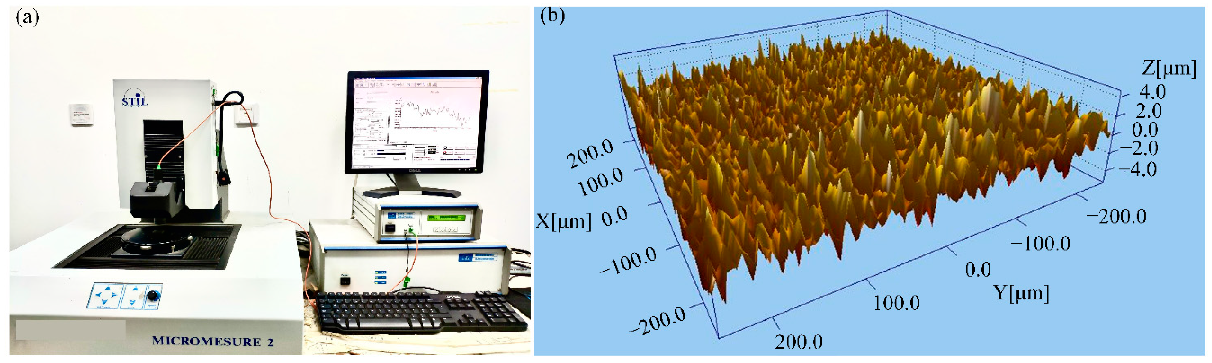
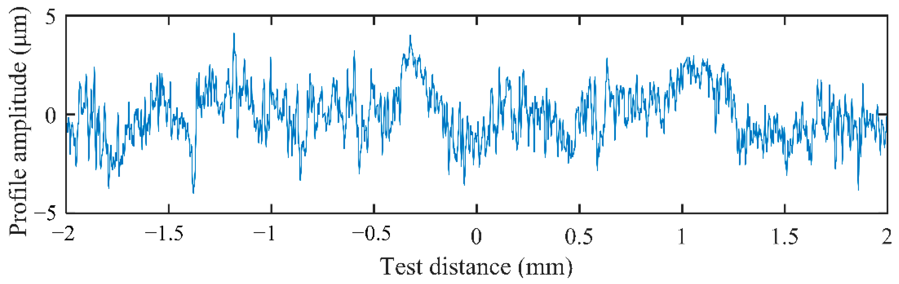
2.1. Measurement of Tooth Surface Topography

The experiments of measurement of the surface profile have been conducted. The test machine is STIL-MICROMESURE 2 (see Figure 1a). For the purpose of improving the reliability of the measurement, three different positions are selected for each specimen. The 3D profiler can automatically obtain the 3D topography of the scanned surface and the probability distribution of the roughness height, as well as the parameters Ra used to characterize the surface roughness. The obtained 3D topography of the scanned surface is shown in Figure 1b.
Taking the measurement results at a certain cross-section position (x = 0 μm), the gear surface profile curve is obtained as shown by Figure 2. Through the analysis of the tested profile curve, it can be found that the gear surface profile has self-similarity and shows fractal characteristics. Therefore, the fractal function can be used to characterize the gear surface topography instead of the actual measurement.

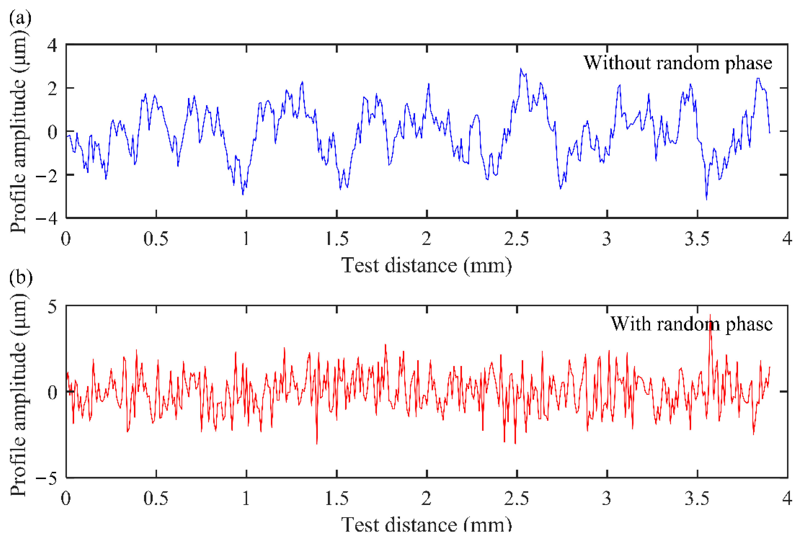
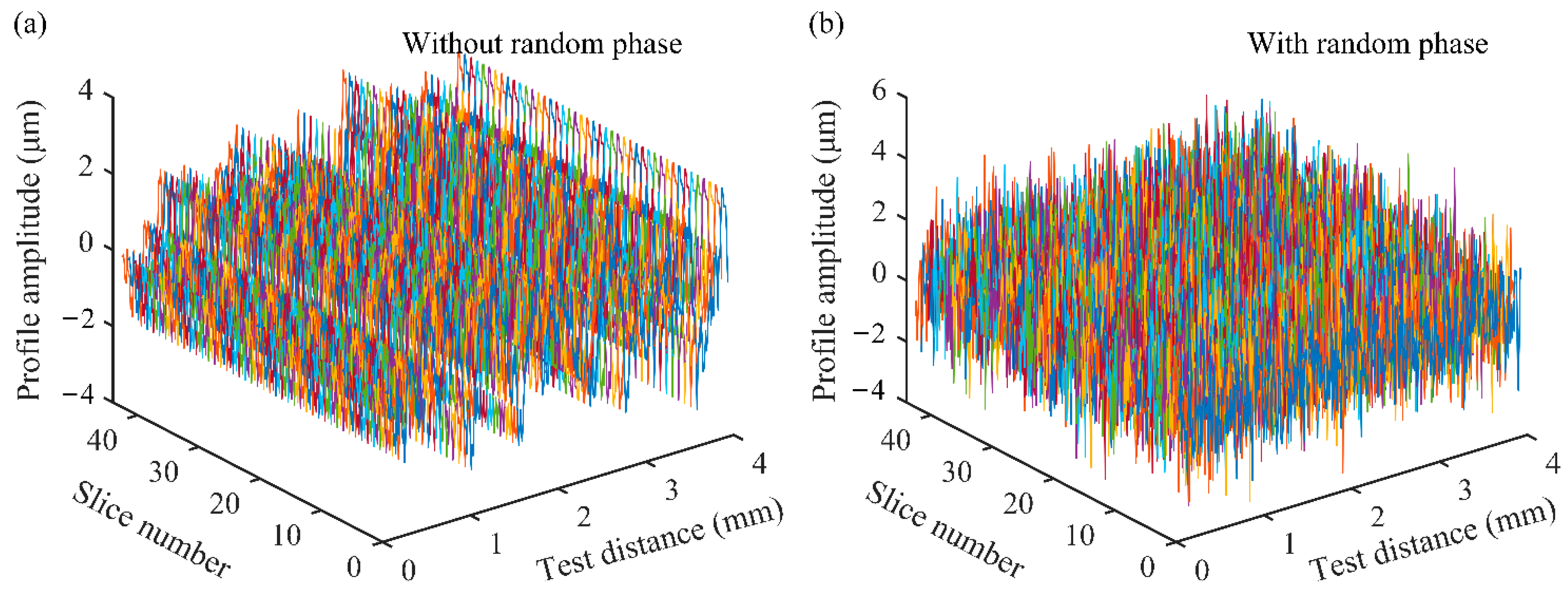
2.2. Tooth Surface Topography Characterization Based on Fractal Function

Under the condition of the same roughness level, different cross-sections have different microtopographies. In order to simulate the difference in the profile, it is necessary to introduce a random phase into the W-M fractal function. The W-M fractal function with the random phase is as follows.
w m ( x ) = G D 1 n = n min n max cos ( 2 π γ n x + φ n ) γ ( 2 D ) n , ( 1 < D < 2 ,   γ = 1.5 ,   0 φ n 2 π )
where wm(x) represents the amplitude of the contour of the two-dimensional rough surface; x is the horizontal measuring length; D stands for the fractal dimension; G means the characteristic scale parameter of profile; n is frequency index of asperities; nmin is the minimum frequency index; nmax represents the maximum frequency index; φn stands for the random phase; and γ is the sampling frequency. The curves of the surface profile simulated by the W-M fractal function without and with the random phase are depicted in Figure 3. It is discovered that the introduction of the random phase has no effect on the amplitude of the profile, however, the profile with the random phase is much closer to the real tested surface (see Figure 2).
Considering the gear with a certain face width, the gear is cut into several thin slices with the same thickness along the face width direction. As the slice is thin, the profile can be characterized by Equation (1). The 3D profile can be obtained by applying Equation (1) to all slices based on the sliced method. The introduction of the random phase ensures the difference in the topography of each slice along the face width direction when the fractal parameters are constant. Taking the number of slices of 20 as an example, the 3D topography without and with considering the random phase is shown in Figure 4.
As can be seen from Figure 4a, without the random phase, the topography of each slice position is the same; after introducing the random phase, the topography of each slice is different (see Figure 4b), and the topography obtained is closer to the actual situation. Therefore, the W-M fractal function with random phase will be used to characterize the profile of the tooth surface in the follow-up study.

3. Model of EHL

The surface profile characterized by the W-M fractal function is introduced into the OFT equation. The EHL model with fractal rough topography is solved by the multi-grid method. Taking the 3D topography of the gear tooth surface into consideration, the gear is divided into thin slices along the face width direction, then OFP and OFT distributions are calculated on each slice. Taking a pair of gears as an example, the OFP and OFT at a certain meshing position with and without considering tooth surface roughness are compared and analyzed. After the OFP and OFT are obtained, the OFS can be calculated, and the influence of smooth and rough gear surface on OFS is analyzed.

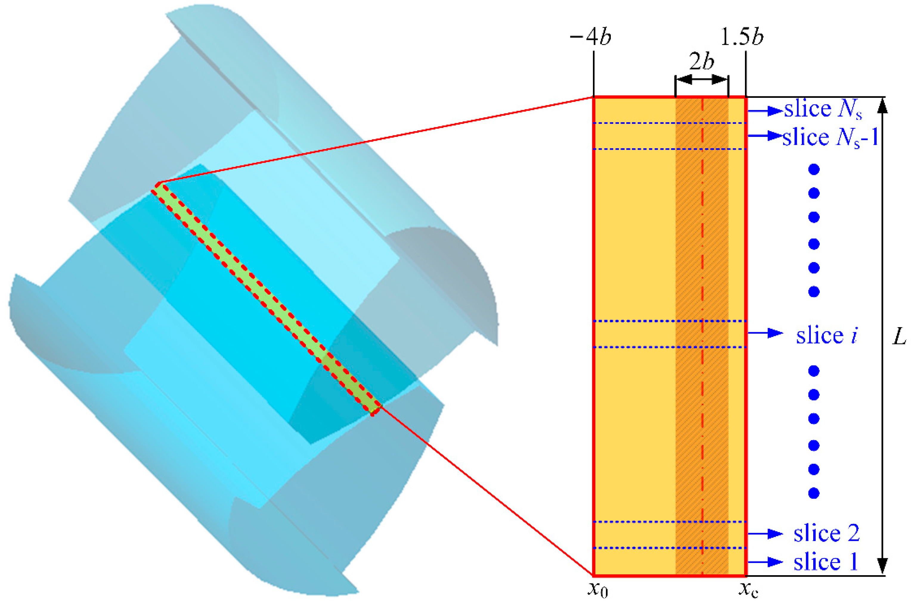
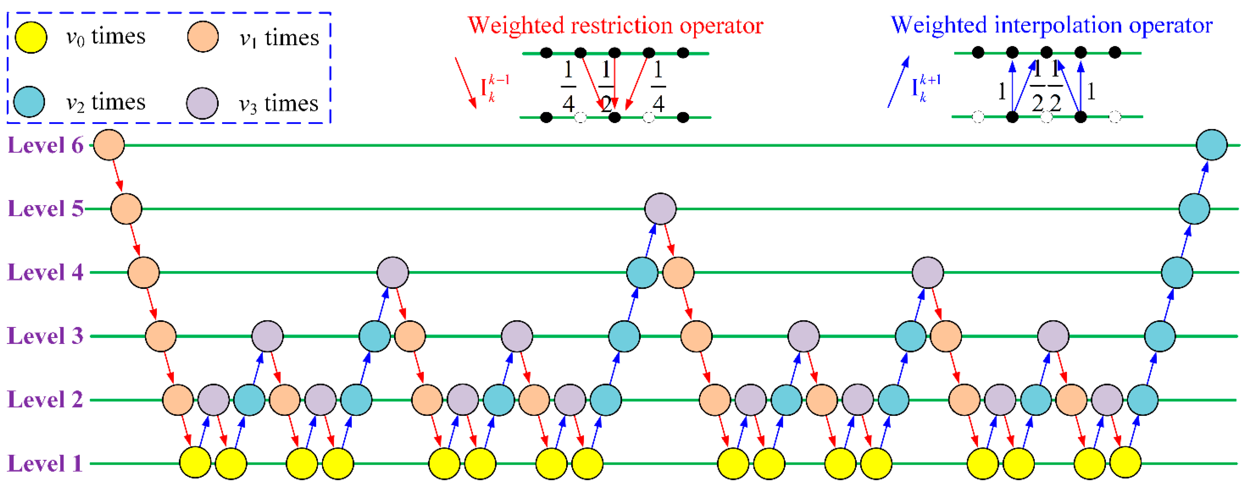
3.1. Solution of EHL Model with Fractal Roughness

The sliced method is adopted to solve the EHL model of each gear slice along the face width direction. On every single slice, a line contact model can be adopted (see Figure 5). In the figure, L is tooth face width; Ns represents the number of slices; x0 and xe represent the oil film inlet coordinate and outlet coordinate, respectively. The value range of [x0, xe] is [−4b, 1.5b] in general, and b represents the contact half width of the gear.
For the line contact problem, the Reynolds equation is:
x ( ρ h 3 12 η p x ) = u s ( ρ h ) x + ( ρ h ) t ,
where x means oil film coordinate; us = (u1 + u2)/2 stands for entrainment velocity; u1 and u2 correspond to the rolling speed at the meshing point of the pinion and gear, respectively; ρ represents lubricant density; h means OFT; p represents OFP; η means lubricant viscosity.
The film thickness equation at each slice needs to consider the fractal rough surface topography of the contact surface, which is obtained by:
h ( x , t ) = h 0 ( t ) + x 2 2 R + v ( x , t ) + w m ( x , t ) ,
where h0(t) stands for initial OFT; wm(x,t) means fractal surface roughness obtained by Equation (1); R stands for the equivalent radius of curvature; v(x,t) represents the elastic deformation, and it is solved by Equation (4). It should be noted that in order to speed up the calculation, the DC-FFT method [41] is adopted in this paper.
v ( x , t ) = 2 π E x 0 x e p ( x , t ) ln ( x x ) 2 d x
where E stands for the equivalent elastic modulus.
The equation of fluid viscosity varying with pressure is as follows:
η ( x , t ) = η 0 exp { [ ln ( η 0 ) + 9.67 ] [ 1 + ( 1 + p ( x , t ) p 0 ) z ] } ,
where η0 stands for the initial lubricant viscosity under ambient pressure; z means the viscosity–pressure index; p0 represents the pressure coefficient.
The oil film density is a function of pressure, which is determined by Equation (6).
ρ ( x , t ) = ρ 0 0.59 × 10 9 + 1.34 p ( x , t ) 0.59 × 10 9 + p ( x , t ) ,
where ρ0 means initial lubricant density under ambient pressure.
In the contact area of each slice, the OFP is balanced with the external load, which satisfies the following relationship:
F slice = x o x e p ( x , t ) d x ,
where Fslice is the external load on each slice.
Equations (2)–(7) are solved by the multi-grid method [42]. Figure 6 shows a 6-level W cycle iterative process. I k k 1 is the restriction operator transferred from k level to (k−1) level, and the number of iterations is v1; I k k + 1 is the interpolation operator transferred from k level to (k + 1) level, and the number of iterations is v2; v3 is the number of iterations when the operator is changed, and usually v3= v1+ v2; v0 is the number of iterations of the lowest level. As an improvement on the classical multi-grid method, the Gauss–Seidel relaxation is adopted in the low-pressure region and the dipole Jacobi relaxation method is used in the high-pressure region [23].
The pseudocode of EHL algorithm considering fractal roughness is shown in Algorithm 1.
Algorithm 1 Rough EHL solved by multi_grid
Input: Paras—gear conditions, rough topography, grid properties
Output: P—film pressure, H—film thickness
1: function RoughEHL (Paras)
2:   while ErrWW && ErrPP do
3:     S(k) = 0 (k = 16); k 6
4:     while k > 1 do
5:       relax v1 to iterate P by Gauss–Seidel or dipole Jacobi
6:       S(k) = S(k) + 1
7:       restrict P; k = k − 1
8:     end while
9:     relax v0 to iterate P at Level 1
10:     interpolate P; k = k + 1
11:     relax v2 to iterate P
12:     if k ≠ 6 then
13:       if S(k) == 2 then
14:         S(k) 0
15:         goto 10
16:       else
17:         goto 4
18:       end if
19:     else
20:       obtain P, H at Level 6
21:     end if
22:     calculate ErrW, ErrP
23:   end while
24:   return P, H
25: end function
Taking a pair of spur gears as an example, the lubrication characteristics are analyzed. The gear pair’s parameters are listed in Table 1.
The OFP and OFT curves at a certain meshing position with smooth and rough surface are depicted in Figure 7 and Figure 8, respectively. In the figures, X means the non-dimension oil film coordinate (X= x/b). When the surfaces of the spur gear pair are smooth, the curves of OFP (see Figure 7a) and OFT (see Figure 7b) are distributed exactly the same on each slice.
The arrangement of roughness level is shown in Table 2. However, it can be figured out from Figure 8 that under fractal roughness conditions, the distributions of OFP and OFT on each slice fluctuate. In addition, due to the different topography on each slice, the curves of OFP and OFT are different on each slice. It can also be concluded that with the increase in roughness level, the OFT fluctuates obviously, and the peak value of local pressure increases accordingly, which may cause stress concentration. It is validated that the OFP and OFT distributions illustrated in Figure 8 can better reflect the actual lubrication film state of the gear pair.

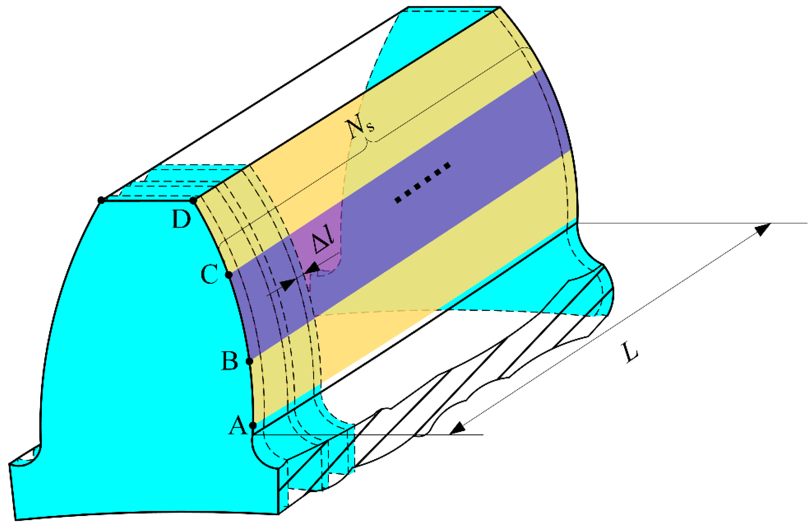
3.2. Calculation of OFS

The spring model is adopted to solve OFS between two rough surfaces [43]. The OFS in the contact area of the gear pair is:
k l = A B l h l ,
where hl is OFT; A means oil film contact area; and Bl is bulk modulus of the lubrication, which is a function of the average OFP. Combined with the OFP p calculated in Section 3.1, Bl can be determined by the following equation:
B l = { 1 1 1 + B 0 log [ 1 + p m B 0 ( 1 + B 0 ) ] } [ B 0 + p m ( 1 + B 0 ) ] ,
the meaning of other parameters in Equation (9) are explained in Ref. [44].
The OFP and OFT along the line of action on each slice of the gear can be obtained from Section 3.1. Then, the total OFS at each meshing point is the sum of stiffness of all slices, which can be obtained by:
K l = n = 1 N s k l n ,
where kln is the OFS of the n-th slice.
For a certain slice, the OFS during the meshing period under smooth oil film contact and rough oil film contact with different roughness levels is depicted in Figure 9a, and the OFS curve of each slice along the face width direction at a certain meshing point P is illustrated in Figure 9b.
It is reflected in Figure 9a that the OFS of the smooth surface is stable with meshing period, while the OFS of the rough surface fluctuates. Moreover, it is observed from Figure 9a that OFS of the smooth surface is larger, and with the increase in roughness level, the stiffness of the oil film becomes lower and lower. The reason may be that for the rough surface, there are many pressure peaks and areas with low film thickness compared with the smooth surface, which affects the OFS. It is generally agreed that when the roughness tends to be 0, the surface tends to be smooth, and the stiffness curve is closer to that of the smooth surface. Moreover, when the gear meshing transforms from a double-tooth contact (DTC) region (the blue shaded areas) to a single-tooth contact (STC) region, the contact stiffness of both cases has a sudden change. It can be concluded from Figure 9b that at a certain meshing position, the OFS of the smooth surface along the face width direction is constant, which is because the distributions of OFP and OFT are the same on each slice (see Figure 7). Meanwhile, the OFS of the rough surface fluctuates, which is due to fluctuation of OFP and OFT caused by the existence of the random phase in the W-M fractal function (see Figure 8).

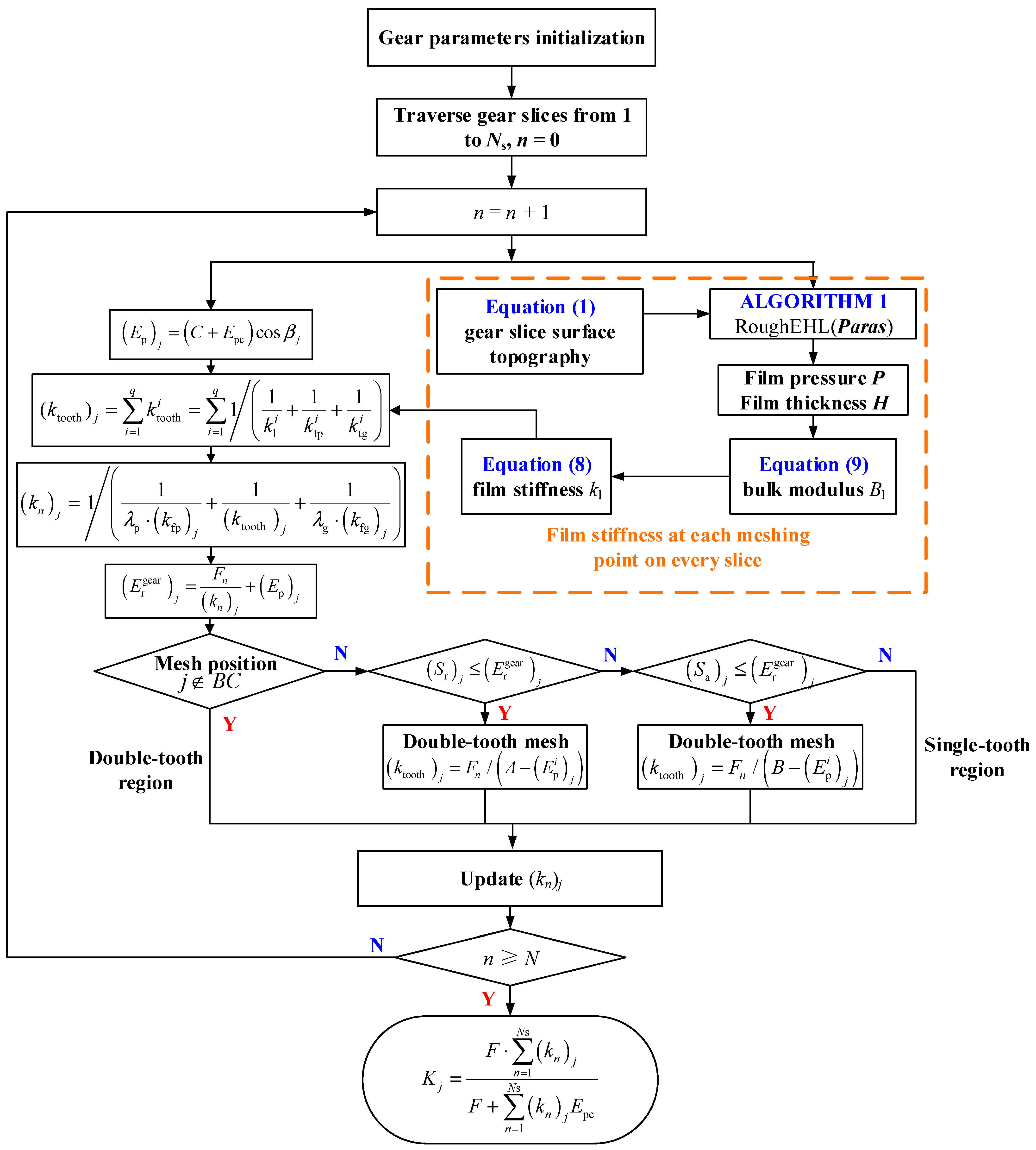
4. Mesh Stiffness Model under Fractal Rough EHL Condition

The OFS and TVMS are calculated based on the analytical method, where the sliced method is adopted to consider the 3D gear surface topography. The OFS calculated in Section 3.2 is taken as the contact stiffness between engaged gear tooth pairs. The contact stiffness and TVMS are compared under the Hertz contact stiffness, smooth OFS, and rough OFS. In addition, the influences of different surface roughness levels, rotational speeds, and torques on the OFS and TVMS are investigated.
To consider the 3D rough topography of the gear tooth surface, the TVMS is calculated by the analytical sliced method. The spur gears are discretized into Ns independent gear slices along the face width direction (as shown in Figure 10). The number of slices Ns is set to be Lll =1mm is the width of each slice). It is assumed that the coupling effect between these independent gear slices is not considered. In the figure, AB and CD represent the theoretical DTC regions, BC represents the theoretical STC region.
Considering that in the double-tooth meshing region, two meshing teeth share one gear foundation, Ref. [44] gives the modified formula for calculating the mesh stiffness (kn is mesh stiffness of each slice):
k n = 1 / ( 1 λ p k fp + 1 k tooth + 1 λ g k fg ) ,
where λp and λg are the correction coefficient of gear foundation stiffness of pinion and gear, respectively; kfp and kfg represent the gear foundation stiffness of pinion and gear, respectively, which is obtained by:
1 k f ( p ,   g ) = cos 2 β E L { L * ( u f S f ) 2 + M * ( u f S f ) + P * ( 1 + Q * tan 2 β ) } ,
the parameters involved in Equation (12) can be found in Ref. [45]. ktooth stands for stiffness of the gear tooth, whose expression is as follows:
k tooth = i = 1 q k tooth i , k tooth i = 1 / ( 1 k l + 1 k tp + 1 k tg ) ,
where q represents the number of tooth pairs involved in engagement simultaneously; k tooth i stands for tooth stiffness of the i-th tooth pair; kl stands for the local contact stiffness (the OFS in Equation (8) substitutes the Hertz contact stiffness in the proposed model); ktp and ktg are structure stiffness of the tooth of pinion and gear, respectively, including bending stiffness kb, shear stiffness ks, and axial compression stiffness ka. The calculation methods of the stiffness mentioned above are as follows:
k tp = 1 / ( 1 k bp + 1 k sp + 1 k ap ) ,   k tg = 1 / ( 1 k bg + 1 k sg + 1 k ag ) ,
{ 1 k b ( p ,   g ) = π 2 α 0 cos β ( y β y 1 ) x β sin β ] 2 E I y 1 d y 1   d γ d γ + a c β cos β ( y β y 2 ) x β sin β ] 2 E I y 2 d y 2 d τ d τ 1 k s ( p ,   g ) = π 2 α 0 1.2 cos 2 β G A y 1 d y 1   d γ d γ + a c β 1.2 cos 2 β G A y 2 d y 2 d τ d τ 1 k a ( p ,   g ) = π 2 α 0 sin 2 β E A y 1 d y 1   d γ d γ + a c β sin 2 β E A y 2 d y 2 d τ d τ .
The meanings of other unexplained parameters in Equation (15) are explained in detail in Ref. [46]. Thus, the total mesh stiffness is the sum of the stiffness of all gear slices, which is written as:
K = F n = 1 N s k n F + n = 1 N s k n E pc ,
where F is the total meshing force. Epc stands for tooth profile errors.
The flow chart for calculating gear mesh stiffness under EHL conditions considering a 3D rough surface is shown in Figure 11.

5. Results and Discussion

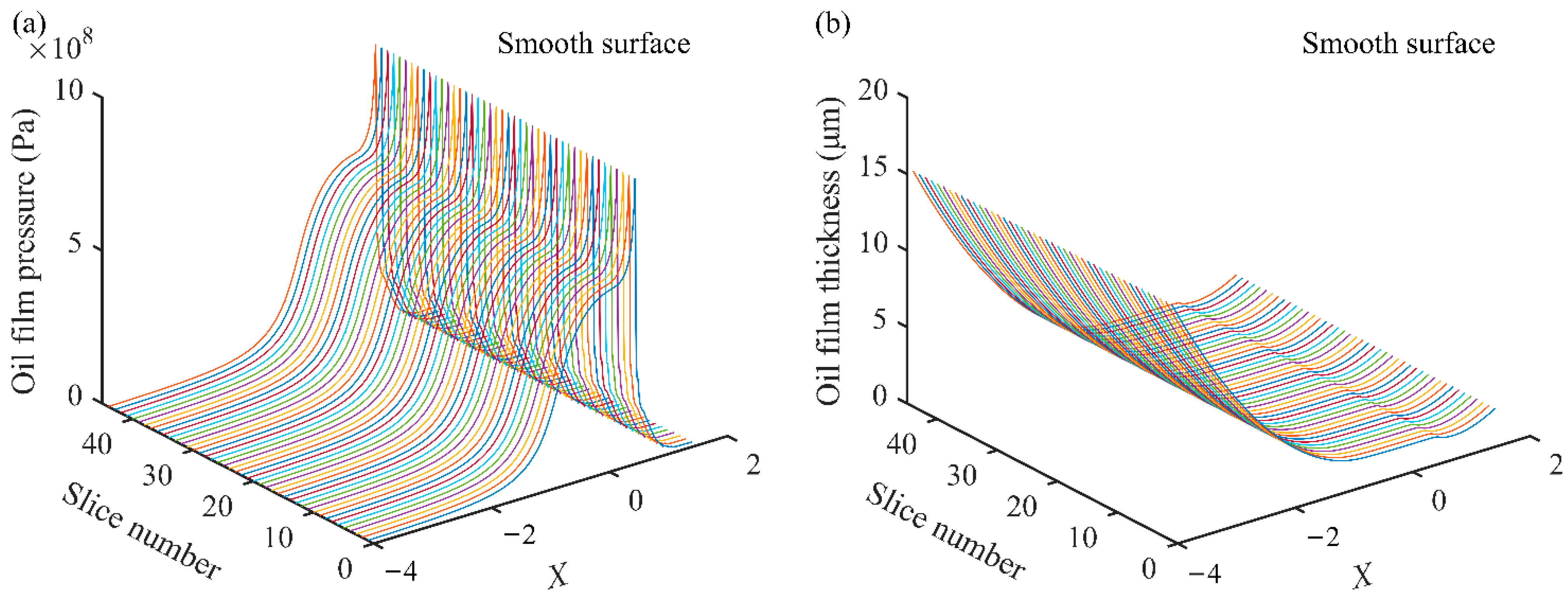
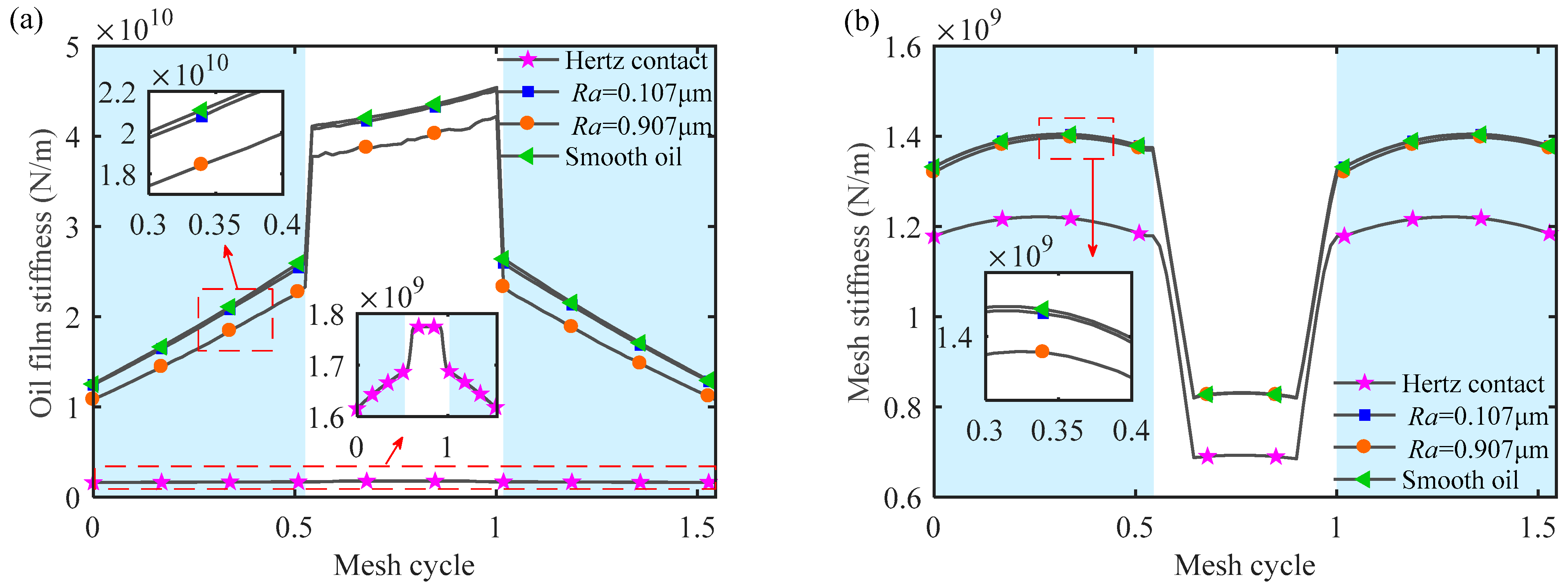
5.1. Mesh Stiffness under Different Contact States

To explore the influence of lubrication on gear meshing characteristics, the OFS and TVMS of the gear pair are solved in the cases of Hertz contact, smooth surface lubrication, and rough surface lubrication, respectively. The arrangement of the roughness level is shown in Table 2. It should be noticed that rough oil film conditions with two different roughness levels (slight roughness level 1 (Ra = 0.107 μm) and severe roughness level 4 (Ra = 0.907 μm)) are investigated to emphasize the differences between these three contact states. The gear pair parameters in Table 2 are taken, and OFS and TVMS results under different contact states are depicted in Figure 12.
The conclusion drawn from Figure 12 is that the existence of lubricating oil film increases TVMS. Mesh stiffness calculated by using the Hertz contact stiffness without considering lubrication is obviously smaller than that when considering the lubrication state. Furthermore, the mesh stiffness of rough surface lubrication is smaller than that of smooth surface lubrication. The reason may be that, for the rough surface, the OFP and OFT distributions appear as many pressure peaks and areas with smaller OFT compared with the smooth surface, thus affecting the OFS. The OFS of the smooth surface is larger. Thus, the mesh stiffness of the smooth surface is larger than that of the rough surface. When the roughness level increases or decreases to a certain extent, the mesh stiffness values are close to the Hertz contact and smooth surface lubrication contact, respectively, which indicates that the proposed model has a certain generality.

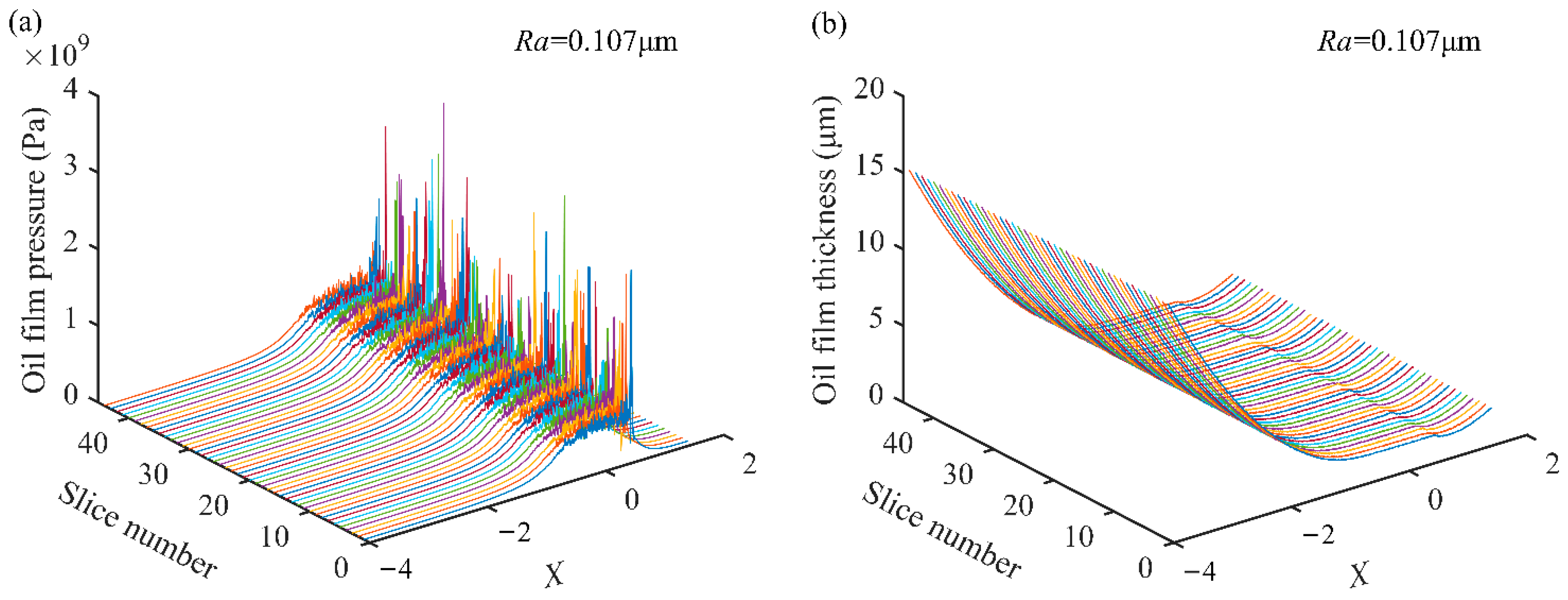
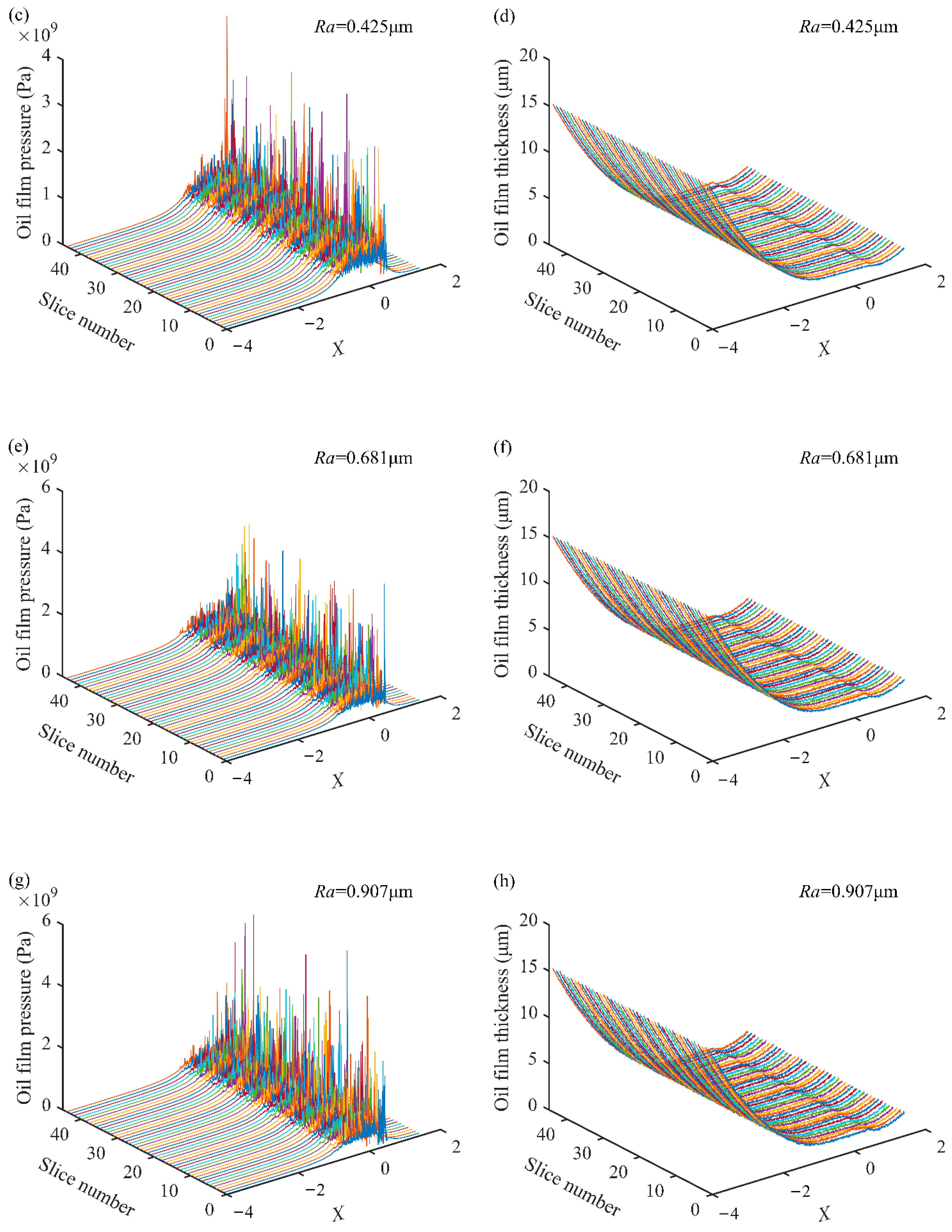
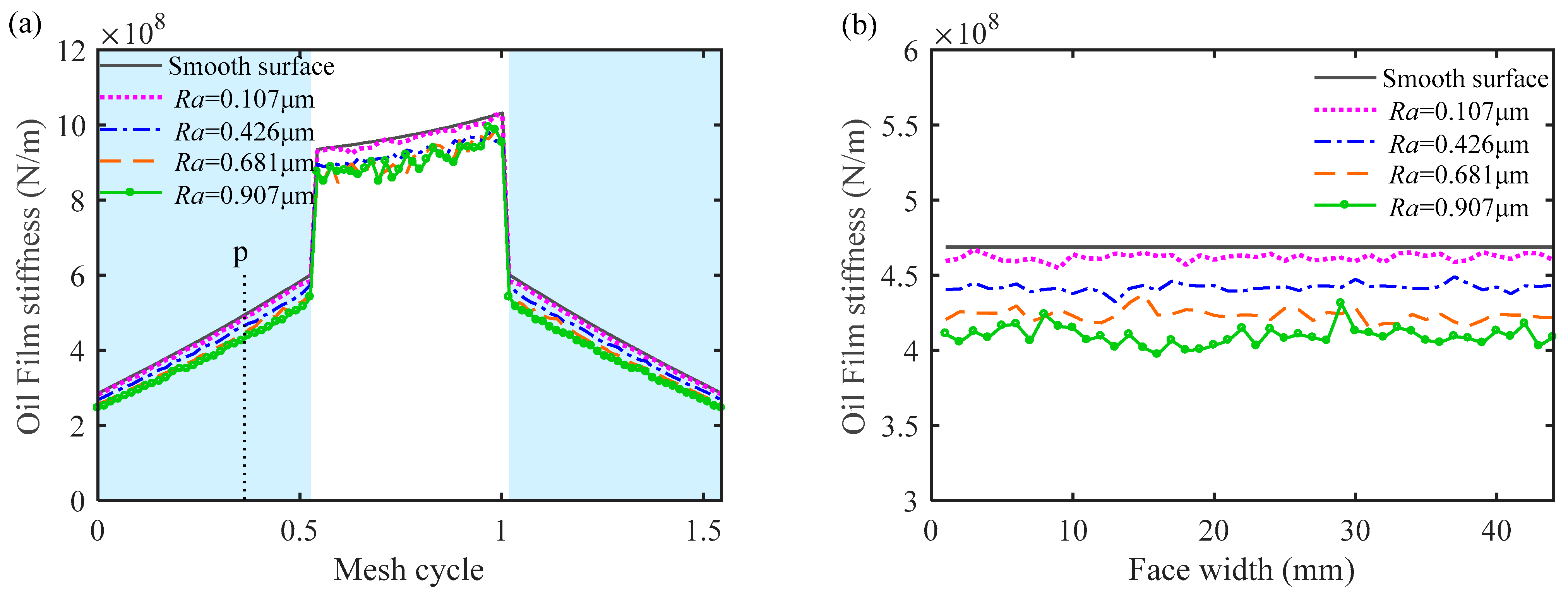
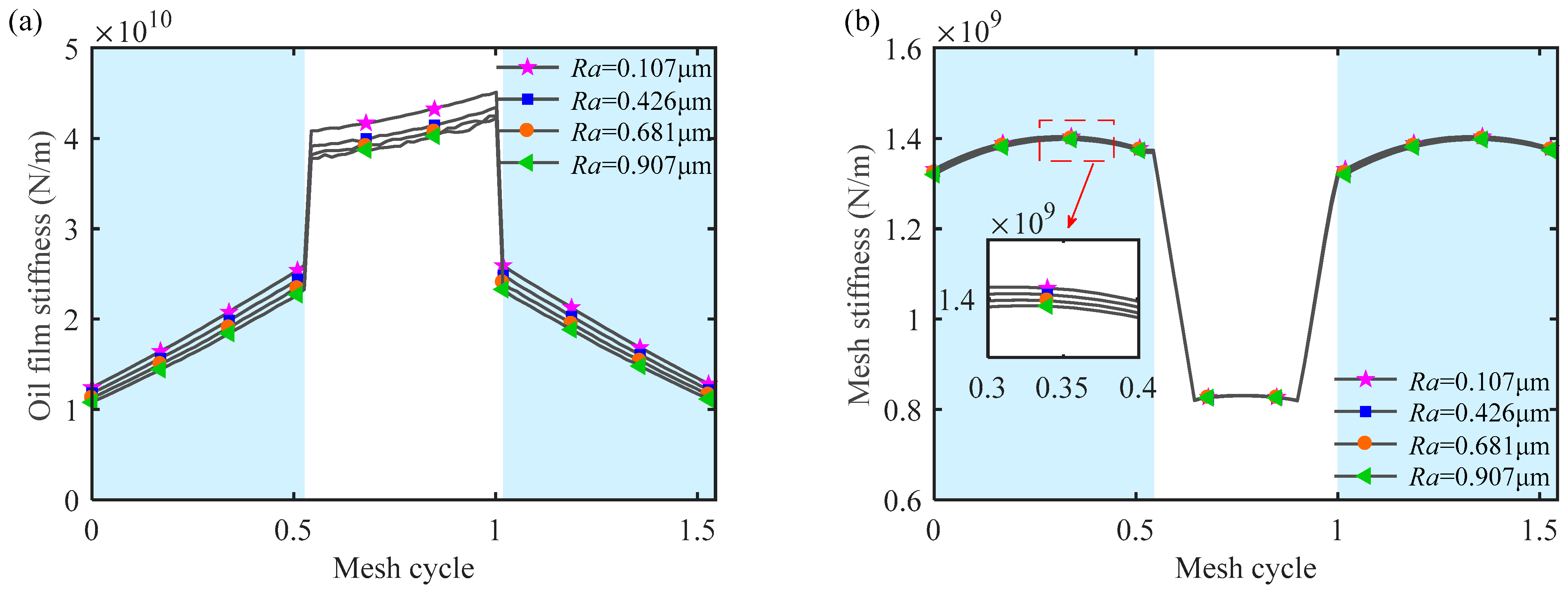
5.2. Mesh Stiffness under Different Roughness Levels

To further explore the effect of roughness on lubrication and meshing performance of gear pairs, the OFS and TVMS under different roughness levels (parameters listed in Table 2) are investigated. The torque is 2000Nm, and rotational speed is 2000 r/min. The OFS and TVMS results are depicted in Figure 13.
It is observed from Figure 13 that the OFS and TVMS decrease with the increase in roughness, and the curves of OFS and TVMS are not smooth. The existence of roughness makes the oil film too thick or too thin locally. Due to the high roughness level and large central OFT, the OFS is small. From the calculation formula of mesh stiffness (Equation (11)), it is concluded that the contact stiffness (that is, OFS) is proportional to mesh stiffness, so the greater the roughness is, the smaller the gear mesh stiffness is.

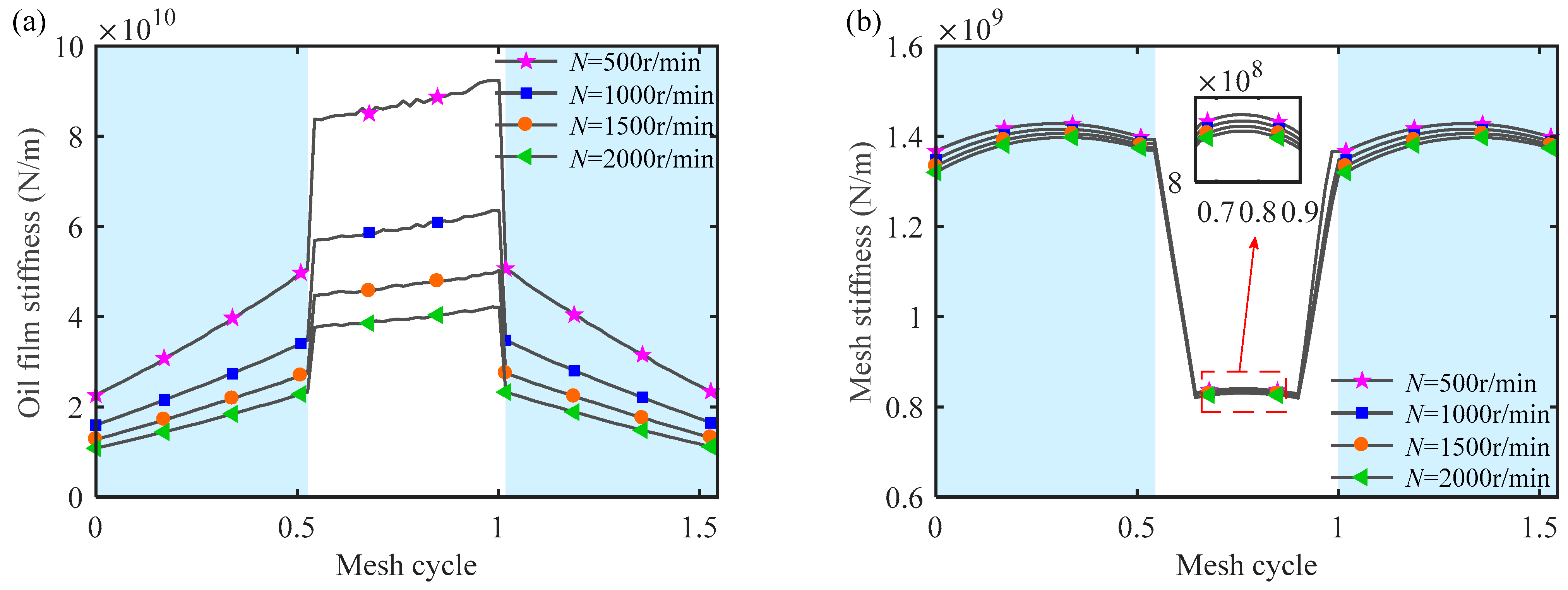
5.3. Mesh Stiffness under Different Rotational Speeds

The OFS and TVMS under the condition of rough surface lubrication (roughness level 4 in Table 2 is adopted) at different rotational speeds are investigated, and the torque is set to be 2000 Nm. The OFS and TVMS results are shown in Figure 14.
From Figure 14, it is concluded that the higher the rotational speed, the smaller the OFS and TVMS. Under high rotational speed conditions, a thicker oil film is more easily formed, and the thicker the oil film is, the smaller the OFS is, which leads to the decrease in the TVMS of the gear pair. In addition, because the sliding speed of the DTC region is lower than that of the STC region, oil film may be more easily formed in the DTC region. Thus, the influence of rotational speed on the TVMS of the DTC region is more obvious.

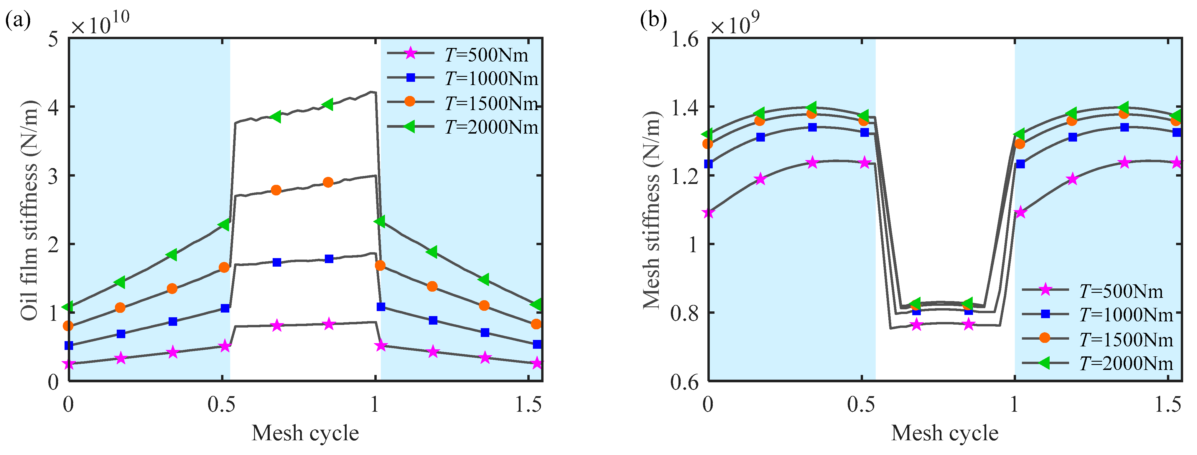
5.4. Mesh Stiffness under Different Torques

The OFS and TVMS under different torques are investigated. The rotational speed is set to be 2000 r/min, and roughness level 4 (see Table 2) is chosen. The results are displayed in Figure 15.
As depicted in Figure 15, the greater the torque, the greater the OFS and TVMS. This is due to the fact that under the action of a heavier load, the OFP increases and the distribution is more uniform, meanwhile, the OFT becomes thinner and the local difference in film thickness decreases, which makes the lubrication more stable. It is also found that the change in torque will make a difference in the transition zone between the DTC region and STC region. Specifically, with the increase in torque, the phenomenon of extended meshing becomes more obvious.

6. Conclusions

Considering different topology distribution along the face width direction and its influence on the distribution of lubricating oil film, an improved model for calculating the oil film stiffness (OFS) and time-varying mesh stiffness (TVMS) of spur gears is established. By adopting the sliced method, the influence of three-dimensional (3D) tooth surface topography on the mesh stiffness of gear pairs can be considered only by solving the 2D elastohydrodynamic lubrication (EHL) model. Thus, the complex and time-consuming solving process of the 3D EHL model can be avoided. The actual gear surface topography is tested by a surface profiler and characterized by the W-M fractal function. The distributions of pressure, thickness, and stiffness of the lubricating oil film are investigated under smooth and rough conditions by solving the proposed EHL model. Taking the OFS as contact stiffness between gear pairs, the TVMS of the gear pair is then calculated by the analytical sliced method. The main conclusions are listed below.
(1) Gear surface topography can be well characterized by a fractal function. The 3D topography of the actual gear tooth surface can be simulated by introducing a random phase.
(2) The oil film pressure (OFP) and oil film thickness (OFT) at a certain meshing position with and without considering tooth surface roughness are compared and analyzed. The OFS is calculated after obtaining OFP and OFT, and the influence of smooth and rough gear surfaces on the OFS is analyzed. The OFS of the rough surface fluctuates during the gear operating process and the amplitude is much smaller than that of the smooth surface.
(3) The TVMS is calculated by taking the OFS as contact stiffness. The mesh stiffness calculated by using the Hertz contact stiffness is obviously smaller than that when considering the lubrication state, and the mesh stiffness of rough surface lubrication is less than that of smooth surface lubrication. Furthermore, under the condition of rough lubrication, the mesh stiffness increases with the decrease in rotational speed and the increase in torque, and decreases with the increase in roughness. Among these three impact factors, the effect of torque on the OFS and TVMS dominates.
The research conclusions of this work can provide some reference for studying the meshing characteristics of gear pairs under EHL conditions considering rough surface topography. It should be claimed that under the roughness levels given in this paper, the gear pair is regarded as operating under the condition of full film lubrication state throughout the whole meshing cycle. In other words, the model proposed in this paper can be applied to gears working under full film lubrication. In practice, it is very difficult for gears to be in a state of adequate oil supply under some extreme working conditions (such as high speed, high temperature, heavy load, etc.). As a result, it is possible to form a lack of lubrication state and produce the squeeze cave effect. Thus, the squeeze cave should be considered in further research.

Author Contributions

Funding acquisition, Y.Y.; Project administration, H.M.; Resources, Y.Y. and H.W.; Writing—original draft, Z.Z.; Writing—review & editing, H.H. and Z.L. All authors have read and agreed to the published version of the manuscript.

Funding

This research was funded by [National Key Laboratory of Science and Technology on Helicopter Transmission] grant number [Grant no. HTL-O-21G03], [National Science and Technology Major Project] grant number [Grant no. J2019-IV-0018-0086] and [Basic Research Project] grant number [Grant no. 20195208003].

Acknowledgments

The authors would like to acknowledge the support of National Key Laboratory of Science and Technology on Helicopter Transmission, National Science and Technology Major Project and Basic Research Project and the China North Vehicle Research Institute.

Conflicts of Interest

The authors declare no conflict of interest.

Nomenclature

AOil film contact area
bContact half width of the gear
BlBulk modulus of the lubrication
c*Tip clearance coefficient
DFractal dimension
EEquivalent modulus of elasticity
E p i Total tooth profile error of the i-th tooth pair of each slice gear pair along line of action
EpcTooth errors of each slice gear caused by lead crowning relief along face width direction
FsliceExternal load on each slice
FTotal meshing force
GCharacteristic scale parameter of the profile
hLubricant film thickness
ha*Addendum coefficient
h0Initial oil film thickness
hlOil film thickness
I k k 1 Restriction operator transferred from k level to (k−1) level
I k k + 1 Interpolation operator transferred from k level to (k- + 1) level
kMesh stiffness
kaAxial compression stiffness
kbBending stiffness
kfp, kfgFoundation stiffness of pinion and gear, respectively
khLocal contact stiffness
klStiffness of the contact area of the oil film
klnOil film stiffness of the n-th slice
KlThe sum of the oil film stiffness of all slices
knMesh stiffness of each slice of gear pair
ksShear stiffness
ktoothStiffness of gear tooth
k tooth i Tooth stiffness of the i-th tooth pair
ktp, ktgStructure stiffness of tooth of pinion and gear, respectively
LFace width
mModule of gear
nFrequency index of the asperity
NRotational speed
nmaxThe maximum frequency index
nminThe minimum frequency index
NsNumber of slices
pLubricant film pressure
p0Pressure coefficient
qNumber of tooth pairs involved in meshing at the same time
REquivalent radius of curvature
RaSurface roughness
rintHub radius of gear
TTransmitted torque
u1, u2Rolling speed at the meshing point of the pinion and gear, respectively
usEntrainment velocity
v(x,t)Elastic deformation
v0, v1, v2 and v3Number of iterations in W cycle iterative process
wm(x,t)Amplitude of the contour of the two-dimensional rough surface
xHorizontal measuring length
x0Oil film inlet coordinate
xeOil film outlet coordinate
ZNumber of teeth of gear
zViscosity–pressure index
znAxial coordinate of a sliced spur gear
Greek symbols
αPressure angle of pitch circle
γSampling frequency
ηLubricant viscosity
η0Initial lubricant viscosity under ambient pressure
λp, λgCoefficients of the fillet-foundation stiffness of the pinion and gear, respectively
νPoisson’s ratio
ρLubricant density
ρ0Initial lubricant density under ambient pressure
φnRandom phase
Abbreviations
DTCDouble-tooth contact
EHLElastohydrodynamic lubrication
OFPOil film pressure
OFSOil film stiffness
OFTOil film thickness
STCSingle-tooth contact
TVMSTime-varying mesh stiffness
2DTwo-dimensional
3DThree-dimensional

References

  1. Zhou, W.; Tang, J.; Shao, W. Study on surface generation mechanism and roughness distribution in gear profile grinding. Int. J. Mech. Sci. 2020, 187, 105921. [Google Scholar] [CrossRef]
  2. Chen, K.; Huangfu, Y.; Ma, H.; Xu, Z.; Li, X.; Wen, B. Calculation of mesh stiffness of spur gears considering complex foundation types and crack propagation paths. Mech. Syst. Signal Process. 2019, 130, 273–292. [Google Scholar] [CrossRef]
  3. Huangfu, Y.; Chen, K.; Ma, H.; Li, X.; Han, H.; Zhao, Z. Meshing and dynamic characteristics analysis of spalled gear systems: A theoretical and experimental study. Mech. Syst. Signal Process. 2020, 139, 106640. [Google Scholar] [CrossRef]
  4. Huangfu, Y.; Chen, K.; Ma, H.; Li, X.; Han, H.; Zhao, Z. An improved model for meshing characteristics analysis of spur gears considering fractal surface contact and friction. Mech. Mach. Theory 2021, 158, 104219. [Google Scholar]
  5. Wang, Q.; Xu, K.; Huai, T.; Ma, H.; Wang, K. A mesh stiffness method using slice coupling for spur gear pairs with misalignment and lead crown relief. Appl. Math. Model. 2021, 90, 845–861. [Google Scholar] [CrossRef]
  6. Hou, S.; Wei, J.; Zhang, A.; Zhang, C.; Yan, J.; Wang, C. A novel comprehensive method for modeling and analysis of mesh stiffness of helical gear. Appl. Sci. 2020, 10, 6695–6714. [Google Scholar] [CrossRef]
  7. Chen, Z.; Zhou, Z.; Zhai, W.; Wang, K. Improved analytical calculation model of spur gear mesh excitation with tooth profile deviations. Mech. Mach. Theory 2020, 149, 103838. [Google Scholar] [CrossRef]
  8. Jiang, L.; Deng, Z.; Gu, F.; Ball, A.D.; Li, X. Effect of friction coefficients on the dynamic response of gear systems. Front. Mech. Eng. 2017, 12, 397–405. [Google Scholar] [CrossRef]
  9. Gropper, D.; Wang, L.; Harvey, T.J. Hydrodynamic lubrication of textured surfaces: A review of modeling techniques and key findings. Tribol. Int. 2016, 94, 509–529. [Google Scholar] [CrossRef]
  10. Liu, H.; Liu, H.; Zhu, C.; Parker, R.G. Effects of lubrication on gear performance: A review. Mech. Mach. Theory 2020, 145, 103701. [Google Scholar] [CrossRef]
  11. Chen, S.; Yin, N.; Cai, X.; Zhang, Z. Iteration framework for solving mixed lubrication computation problems. Front. Mech. Eng. 2021, 16, 635–648. [Google Scholar] [CrossRef]
  12. Hu, Y.Z.; Zhu, D. A full numerical solution to the mixed lubrication in point contacts. J. Tribol. 2000, 122, 1–9. [Google Scholar] [CrossRef]
  13. Liu, Y.; Wang, Q.J.; Wang, W.; Hu, Y.; Zhu, D. Effects of differential scheme and mesh density on EHL film thickness in point contacts. J. Tribol. 2006, 128, 641–653. [Google Scholar] [CrossRef]
  14. Zhu, D. On some aspects of numerical solutions of thin-film and mixed elastohydrodynamic lubrication. Part J J. Eng. Tribol. 2007, 221, 561–579. [Google Scholar] [CrossRef]
  15. Akbarzadeh, S.; Khonsari, M.M. Prediction of steady state adhesive wear in spur gears using the EHL load sharing concept. ASME. J. Tribol. 2009, 131, 024503. [Google Scholar] [CrossRef]
  16. Li, S.; Kahraman, A. A transient mixed elastohydrodynamic lubrication model for spur gear pairs. ASME. J. Tribol. 2010, 132, 011501. [Google Scholar] [CrossRef]
  17. Li, S.; Kahraman, A. Prediction of spur gear mechanical power losses using a transient elastohydrodynamic lubrication model. Tribol. Trans. 2010, 53, 554–563. [Google Scholar] [CrossRef]
  18. Elisaus, V.; Mohammadpour, M.; Theodossiades, S.; Rahnejat, H. Effect of teeth micro-geometrical form modification on contact kinematics and efficiency of high performance transmissions. Proc. Inst. Mech. Eng. Part K J. Multi-Body Dyn. 2017, 231, 538–555. [Google Scholar] [CrossRef]
  19. Sivayogan, G.; Rahmani, R.; Rahnejat, H. Lubricated loaded tooth contact analysis and non-Newtonian thermoelastohydrodynamics of high-performance spur gear transmission systems. Lubricants 2020, 8, 20. [Google Scholar] [CrossRef]
  20. Ren, N.; Zhu, D.; Chen, W.W.; Liu, Y.; Wang, Q.J. A three-dimensional deterministic model for rough surface line-contact EHL problems. J. Tribol. 2009, 131, 011501. [Google Scholar] [CrossRef]
  21. Shi, X.; Sun, W.; Lu, X.; Ma, X.; Zhu, D.; Zhao, B.; He, T. Three-dimensional mixed lubrication analysis of spur gears with machined roughness. Tribol. Int. 2019, 140, 105864. [Google Scholar] [CrossRef]
  22. Shi, X.J.; Lu, X.Q.; He, T.; Sun, W.; Tong, Q.S.; Ma, X.; Zhao, B.; Zhu, D. Predictions of friction and flash temperature in marine gears based on a 3D line contact mixed lubrication model considering measured surface roughness. J. Cent. South Univ. 2021, 28, 1570–1583. [Google Scholar] [CrossRef]
  23. Liu, H.; Mao, K.; Zhu, C.; Xu, X. Mixed lubricated line contact analysis for spur gears using a deterministic model. J. Tribol. 2012, 134, 021501. [Google Scholar] [CrossRef]
  24. Liu, H.; Zhu, C.; Sun, Z.; Song, C. Starved lubrication of a spur gear pair. Tribol. Int. 2016, 94, 52–60. [Google Scholar] [CrossRef]
  25. Liu, H.; Liu, H.; Zhu, C.; Wei, P.; Tang, J. Tribological behavior of coated spur gear pairs with tooth surface roughness. Friction 2019, 7, 117–128. [Google Scholar] [CrossRef]
  26. Zhou, Y.; Zhu, C.; Liu, H. A micropitting study considering rough sliding and mild wear. Coatings 2019, 9, 639–644. [Google Scholar] [CrossRef]
  27. Liu, H.; Liu, H.; Zhu, C.; Sun, Z.; Bai, H. Study on contact fatigue of a wind turbine gear pair considering surface roughness. Friction 2020, 8, 553–567. [Google Scholar] [CrossRef]
  28. Jian, G.X.; Wang, Y.Q.; Zhang, P.; Li, Y.K.; Luo, H. Thermal elastohydrodynamic lubrication of modified gear system considering vibration. J. Cent. South Univ. 2020, 27, 3350–3363. [Google Scholar] [CrossRef]
  29. Yin, L.; Deng, C.L.; Yu, W.N.; Shao, Y.M.; Wang, L.M. Dynamic characteristics of gear system under different micro-topographies with the same roughness on tooth surface. J. Cent. South Univ. 2020, 27, 2311–2323. [Google Scholar] [CrossRef]
  30. Xiao, H.; Sun, Y.; Xu, J. Investigation into the normal contact stiffness of rough surface in line contact mixed elastohydrodynamic lubrication. Tribol. Trans. 2018, 61, 742–753. [Google Scholar] [CrossRef]
  31. Sun, Y.; Xiao, H.; Xu, J.; Yu, W. Study on the normal contact stiffness of the fractal rough surface in mixed lubrication. Part J: J. Eng. Tribol. 2018, 232, 1604–1617. [Google Scholar] [CrossRef]
  32. Zhou, C.; Xiao, Z.; Chen, S.; Han, X. Normal and tangential oil film stiffness of modified spur gear with non-Newtonian elastohydrodynamic lubrication. Tribol. Int. 2017, 109, 19–327. [Google Scholar] [CrossRef]
  33. Cheng, G.; Xiao, K.; Wang, J.; Pu, W.; Han, Y. Gear contact stiffness under mixed lubrication status. J. Jilin Univ. Eng. Technol. Ed. 2020, 50, 494–503. [Google Scholar]
  34. Cheng, G.; Xiao, K.; Wang, J.; Pu, W.; Han, Y. Calculation of gear meshing stiffness considering lubrication. J. Tribol. 2020, 142, 031602. [Google Scholar] [CrossRef]
  35. Wang, S.; Zhu, R. An improved mesh stiffness model of helical gear pair considering axial mesh force and friction force influenced by surface roughness under EHL condition. Appl. Math. Model. 2022, 102, 453–471. [Google Scholar] [CrossRef]
  36. Wang, X.; Xiang, C.; Li, C.; Li, S.; Shao, Y.; Wang, L. Effect of roughness on meshing power loss of planetary gear set considering elasto-hydrodynamic lubrication. Adv. Mech. Eng. 2020, 12, 1687814020908422. [Google Scholar] [CrossRef]
  37. Huang, K.; Xiong, Y.; Wang, T.; Chen, Q. Research on the dynamic response of high- contact-ratio spur gears influenced by surface roughness under EHL condition. Appl. Surf. Sci. 2017, 392, 8–18. [Google Scholar] [CrossRef]
  38. Wei, J.; Zhang, A.; Gao, P. A study of spur gear pitting under EHL conditions: Theoretical analysis and experiments. Tribol. Int. 2016, 94, 146–154. [Google Scholar] [CrossRef]
  39. Huangfu, Y.; Dong, X.; Chen, K.; Tu, G.; Long, X.; Peng, Z. A tribo-dynamic based pitting evolution model of planetary gear sets: A topographical updating approach. Int. J. Mech. Sci. 2022, 220, 107157. [Google Scholar] [CrossRef]
  40. Wang, L.; Deng, C.; Xu, J.; Yin, L.; Yu, W.; Ding, X.; Shao, Y.; Huang, W.; Yang, X. Effects of spalling fault on dynamic responses of gear system considering three-dimensional line contact elasto-hydrodynamic lubrication. Eng. Fail. Anal. 2022, 132, 105930. [Google Scholar] [CrossRef]
  41. Liu, S.; Wang, Q.; Liu, G. A versatile method of discrete convolution and FFT (DC-FFT) for contact analyses. Wear 2000, 243, 101–111. [Google Scholar] [CrossRef]
  42. Venner, C.H.; ten Napel, W.T.; Bosma, R. Advanced multilevel solution of the EHL line contact problem. J. Tribol. 1990, 112, 426–431. [Google Scholar] [CrossRef]
  43. Dwyer-Joyce, R.S.; Reddyhoff, T.; Zhu, J. Ultrasonic measurement for film thickness and solid contact in elastohydrodynamic lubrication. J. Tribol. 2011, 133, 031501. [Google Scholar] [CrossRef]
  44. Ma, H.; Zeng, J.; Feng, R.; Pang, X.; Wen, B. An improved analytical method for mesh stiffness calculation of spur gears with tip relief. Mech. Mach. Theory 2016, 98, 64–80. [Google Scholar] [CrossRef]
  45. Sainsot, P.; Velex, P.; Duverger, O. Contribution of gear body to tooth deflections–a new bidimensional analytical formula. J. Mech. Des. 2004, 126, 748–752. [Google Scholar] [CrossRef]
  46. Sun, Y.; Ma, H.; Huangfu, Y.; Chen, K.; Che, L.; Wen, B. A revised time-varying mesh stiffness model of spur gear pairs with tooth modifications. Mech. Mach. Theory 2018, 129, 261–278. [Google Scholar] [CrossRef]
Figure 1. Measurement of gear tooth surface: (a) 3D surface profiler (STIL-MICROMESURE 2); (b) gear surface topography.
Machines 10 00705 g001
Figure 2. Topography of tested gear surface.
Machines 10 00705 g002
Figure 3. Topography of gear surface based on W-M fractal function: (a) without random phase; (b) with random phase.
Machines 10 00705 g003
Figure 4. The 3D topography of tooth surface of spur gear pair: (a) without random phase; (b) with random phase.
Machines 10 00705 g004
Figure 5. Schematic of the sliced EHL model.
Machines 10 00705 g005
Figure 6. Schematic diagram of W cycle.
Machines 10 00705 g006
Figure 7. OFP and OFT curve of smooth surface: (a) OFP; (b) OFT.
Machines 10 00705 g007
Figure 8. OFP and OFT curve of rough surface: (a) OFP with Ra = 0.907 μm; (b) OFT with Ra = 0.907 μm; (c) OFP with Ra = 1.609 μm; (d) OFT with Ra = 1.609 μm; (e) OFP with Ra = 3.256 μm; (f) OFT with Ra = 3.256 μm; (g) OFP with Ra = 6.238 μm; (h) OFT with Ra = 6.238 μm.
Machines 10 00705 g008aMachines 10 00705 g008b
Figure 9. OFS: (a) along the line of action; (b) along face width direction at meshing position P.
Machines 10 00705 g009
Figure 10. Sliced gear model.
Machines 10 00705 g010
Figure 11. Flow chart of calculation of TVMS under EHL conditions with 3D surface topography.
Machines 10 00705 g011
Figure 12. OFS and TVMS of gear under different contact modes: (a) OFS; (b) TVMS.
Machines 10 00705 g012
Figure 13. OFS and TVMS of gear under different roughness levels: (a) OFS; (b) TVMS.
Machines 10 00705 g013
Figure 14. OFS and TVMS of gear under different rotational speeds: (a) OFS; (b) TVMS.
Machines 10 00705 g014
Figure 15. OFS and TVMS of gear under different torque: (a) OFS; (b) TVMS.
Machines 10 00705 g015
Table 1. Main parameters of the gear pair.
ParametersPinion/GearParametersPinion/Gear
Tooth number Z45/34Addendum modification coefficient0.37/0.34
Module m (mm)6Addendum coefficient ha*1
Face width L (mm)44Tip clearance coefficient c*0.25
Hub radius rint (mm)81.5/80Elastic modulus E (GPa)207
Pressure angle α (°)20Poisson’s ratio ν0.29
Torque T (N·m)2000Rotational speed N (r/min)2000
Table 2. Roughness and fractal parameters.
Roughness LevelRa/μmDG
10.1071.6921.669 × 10−6
20.4251.5963.528 × 10−6
30.68115654.513 × 10−6
40.9071.5465.229 × 10−6
Publisher’s Note: MDPI stays neutral with regard to jurisdictional claims in published maps and institutional affiliations.

