Article

Dynamics Optimization Research and Dynamics Accuracy and Reliability Analysis of a Multi-Link Mechanism with Clearances

1
Department of Electrical and Information, Shandong University of Science and Technology, Jinan 250031, China
2
Swinburne College, Shandong University of Science and Technology, Jinan 250031, China
*
Author to whom correspondence should be addressed.
Machines 2022, 10(8), 698; https://doi.org/10.3390/machines10080698
Submission received: 14 July 2022 / Revised: 12 August 2022 / Accepted: 12 August 2022 / Published: 16 August 2022
(This article belongs to the Section Machine Design and Theory)

Abstract

:
With the development of high-speed and lightweight mechanisms, and the continuous improvement of manufacturing accuracy requirements in industrial production, clearance joints have increasingly become one of the key factors affecting dynamics performance. Poor clearance will seriously compromise stability, accuracy, and dynamics performance. Based on a genetic algorithm, an efficient modeling methodology for the dynamics optimization of a planar complex multi-link mechanism containing multiple clearance joints is put forward. The model comprises a 2-degree of freedom (DOF) nine-bar mechanism that can be used as the main transmission mechanism of a hybrid drive multi-link press, which is taken as the research object. The optimization objective is to minimize the maximum acceleration of the slider and minimize the difference between the actual central trajectory and the ideal trajectory. By optimizing the quality parameters of key components, an optimal solution for the design parameters is obtained, and the effects of the different optimizations of the objective functions on dynamics response are compared and analyzed. At the same time, a new modeling and calculation methodology of the dynamics accuracy and reliability of a complex multi-link mechanism in terms of multiple clearances is proposed, and the effect of optimization on dynamics accuracy and the reliability of the mechanism is analyzed. Based on the optimization results obtained by taking the minimum difference between the actual center trajectory and the ideal trajectory as an optimization objective, the nonlinear characteristics before and after optimization are analyzed through a phase diagram and Poincaré map. A test platform was built to study the dynamics of the mechanism with clearances. Research not only provides a basis for the dynamics optimization of a multi-link mechanism containing clearances but also provides reference significance for the reliability analysis of a multi-link mechanism containing clearances.

1. Introduction

As an important element of mechanical structures, the multi-link mechanism has the advantages of a simple structure, good reliability, and strong bearing capacity. In recent years, it has been the focus of mechanism research and has attracted the attention of many scholars. In the analysis of such a mechanism’s motion, it is usually assumed that a kinematic pairing is ideal. However, in practice, the clearance of kinematic pairing is inevitable due to tolerances in the design, manufacturing defects, and wear. Clearances will increase certain additional and uncontrollable degrees of freedom, cause additional wear, and impact various elements in the kinematic pair. It will also lead to the deterioration of dynamics performance or adverse vibrations and will mean that the dynamics behavior of the actual mechanism with clearance will deviate from the dynamics behavior of an ideal mechanism. The degree of freedom brought by a clearance joint is a significant source of error [1,2,3,4,5,6,7,8,9,10,11]. Aiming at the problems of low stability and intensified wear during the operation of a mechanism containing clearances, according to its kinematic and dynamics characteristics, we addressed this problem through the dynamics optimization of a mechanism with a clearance. The vibration and noise caused by poor clearance can be effectively reduced and the stability and reliability of the mechanism could be improved [12,13,14].
How to reduce the adverse effects of clearances on dynamics performance and improve the accuracy and performance of mechanisms is a hot topic. Many scholars have carried out a series of theoretical studies examining this problem. Based on the continuous contact model, some scholars have carried out the dynamics optimization of a four-bar mechanism containing revolute clearances [15,16]. Sardashti et al. [15] assumed a four-bar mechanism, considering a single clearance as an example, and proposed an algorithm based upon particle swarm optimization to solve the optimization problem. Erkaya et al. [16] regarded kinematic clearance as a massless virtual rigid bar; they established a dynamics equation for a four-bar mechanism, considering revolute clearance using the Lagrange equation, and optimized the parameters at joint clearance with a genetic algorithm. Based on the Taguchi method, Meng et al. [17] considered clearance, the pin radius, and the friction factor as controllable factors and used collision force as the noise factor to optimize the transmission mechanism of a high-voltage circuit breaker and found that the three controllable factors can effectively affect the dynamics performance of the mechanism. Bai et al. [18] established the normal contact force at clearance by using a nonlinear spring-damper model. The influence of the clearance of a kinematic pair on the dynamics response of a satellite antenna mechanism is studied, and a dynamics optimization method for a satellite antenna driving mechanism with clearance was proposed. Li et al. [19] analyzed the dynamics response and optimized design of a planar rigid–flexible-coupling crank-slider mechanism with double clearances, established a motion differential equation based on the absolute node coordinate method, and studied the effects of a single clearance joint, double clearance joints, and harmonic drive on rigid body dynamics and the rigid–flexible coupling dynamics of the mechanism. Varedi et al. [20] proposed an optimization methodology for a crank-slider mechanism containing clearances based on the particle swarm optimization algorithm, which reduces or eliminates the collision force at the clearance joint by optimizing the mass, centroid position, the moment of inertia of the connection rod, and the mass of the end effector. Sun et al. [21] took a crank-slider mechanism as an example to carry out kinematic analysis and a robust optimization design for a mechanical system containing clearances and proposed a prediction methodology, based on the Baumgarte method and confidence region methodology, to analyze the motion error of a mechanical system. In order to improve the pointing accuracy of a satellite antenna, Ding et al. [22] took the deployment mechanism of a plate satellite antenna as the research object, studied the influence of revolute clearance on pointing accuracy, proposed an analytical method of block modeling using the matrix method, optimized the model based on the particle swarm optimization algorithm, and obtained an optimal solution with a specific configuration. Li et al. [23] optimized the dynamics of the actuator of a multi-link articulated high-voltage circuit breaker with clearance, using the selected clearance size as a design variable. Daniali et al. [24] proposed a comprehensive optimization methodology for the kinematic optimization and dynamics optimization of a four-bar mechanism while considering clearance at the same time, which can reduce the collision of a clearance pair in terms of the dynamics response of the whole mechanism by modifying the mass distribution of the rod, and solved this highly nonlinear optimization problem based upon particle swarm optimization. Ahmedalbashir et al. [25] added a spring between the connecting rod and the swing rod to improve the dynamics responses of a planar four-bar mechanism containing clearances and improve the mechanism’s dynamics performance.
Dynamics accuracy refers to the accuracy changes of a mechanism under the influence of working conditions. The reliable performance of dynamics accuracy could better reflect the actual situation of the mechanism. However, research on the dynamics reliability of a mechanism with clearance has mainly focused on a simple mechanism containing a single clearance, while studies on the reliability of the kinematic and mechanical characteristics of a complex mechanism with multiple clearances were relatively few. Gao et al. [26] analyzed the reliability and sensitivity of a crank-slider mechanism considering multiple clearances and optimized the design of a mechanism containing several clearances, based on an analysis of the design’s reliability and sensitivity. Zhang et al. [27] proposed a novel time-dependent reliability methodology to forecast the probability of meeting specific motion requirements within a predetermined time. Through the analysis of many kinds of four-bar mechanisms, the effectiveness of this method was proved. Wei et al. [28] introduced a reliability sensitivity analysis of time-varying parameters and a global reliability sensitivity analysis. An envelope function methodology and the first-order approximation of a motion error function were introduced to effectively estimate several time-dependent PRS and GRS indices. The importance and effectiveness of the proposed methodology were proved with a four-bar mechanism and automobile rack and pinion steering linkage. Zhang et al. [29] took a multi-loop Hoberman radial linkage as their research object, its reliability having been analyzed. Based on the effective length model, the influence of universal joint clearance on dynamics response was established, and the position deviation of the mechanism was analyzed with an improved loop increment methodology. A reliability evaluation model based on the probability density function was established, and the structure of the mechanism was optimized. Chen et al. [30] took a 2-DOF seven-bar mechanism containing clearances as an example, for which a dynamics accuracy and reliability model was established based upon the stress strength interference theory. The influences of the different parameters on dynamics accuracy and the reliability of the mechanism were studied. Yu et al. [31] built a comprehensive reliability analysis model of a rolling bearing. By modeling the probability distribution of an actual bearing’s working clearance and studying the life factor, the reliability of the results was analyzed. Zhao et al. [32] analyzed the reliability of a slider’s displacement of a crank-slider mechanism containing clearance and friction and investigated the effect of different random parameters on the reliability of the slider’s displacement.
To sum up, the working of a clearance pair leads to a series of problems, such as poor stability, high noise levels, and intensified wear of the mechanism, which reduces the stability, accuracy, and service life of the mechanism. Therefore, it is urgent to optimize the dynamics of a mechanism with clearance to reduce the negative impact of clearance on the dynamics response of the mechanism. However, the published research on the optimization of a mechanism with clearance mainly focuses on a simple mechanism with a single rotating-pair clearance or on improving the performance of the mechanism by adding springs. There are relatively few studies on the dynamics optimization of a complex mechanism with multiple clearances. The center track at a clearance joint reflects the real motion track of the shaft in the bearing, including their function in free flight mode, continuous contact mode, and impact mode, which directly determines the mechanism’s dynamics performance. It is necessary to optimize and improve the dynamics performance of a multi-link mechanism with multiple clearances by reducing the difference between an actual center track and an ideal track, so as to reduce the adverse impact caused by clearance. Clearance exists in almost all motion mechanisms and has a significant impact on motion accuracy. Reliability analysis of a mechanism with clearance has important research significance and application value as a way to improve a mechanism’s reliability.
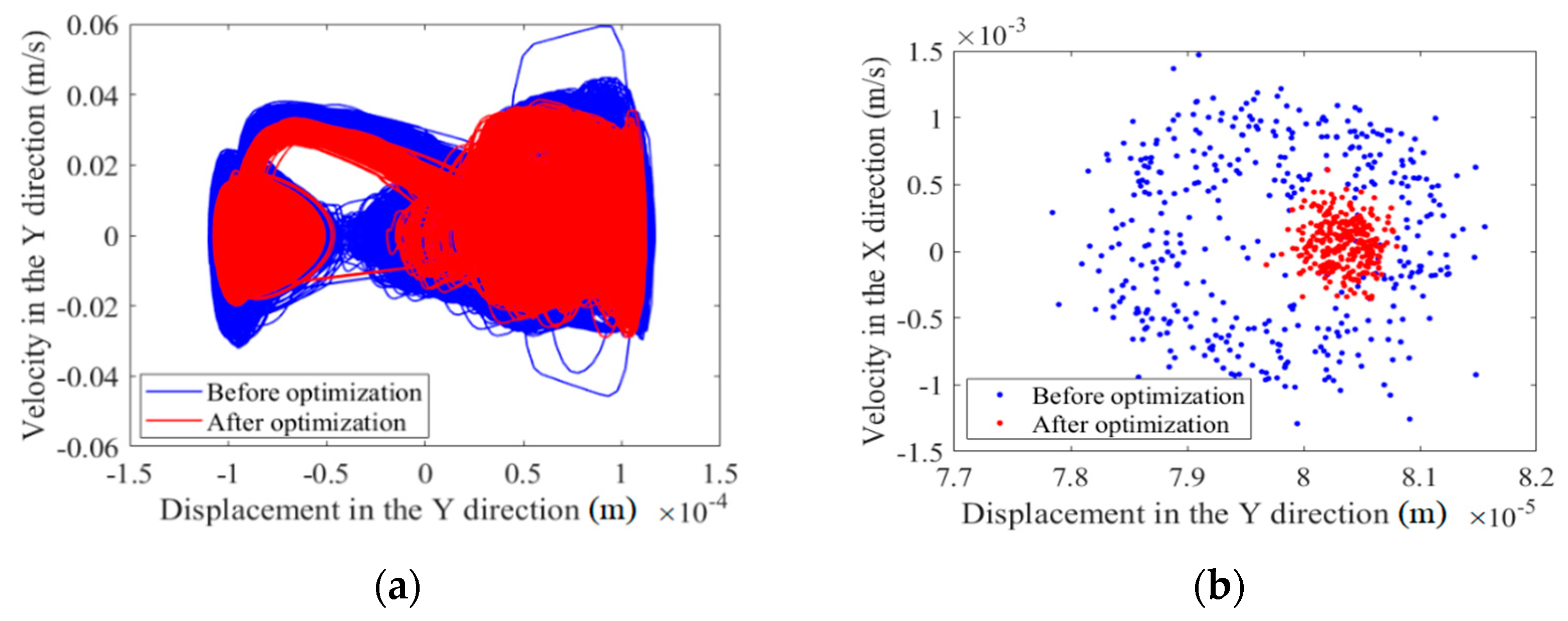
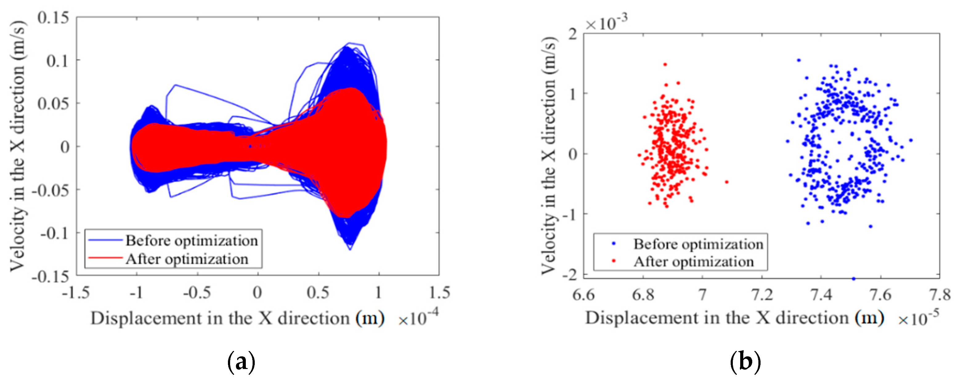
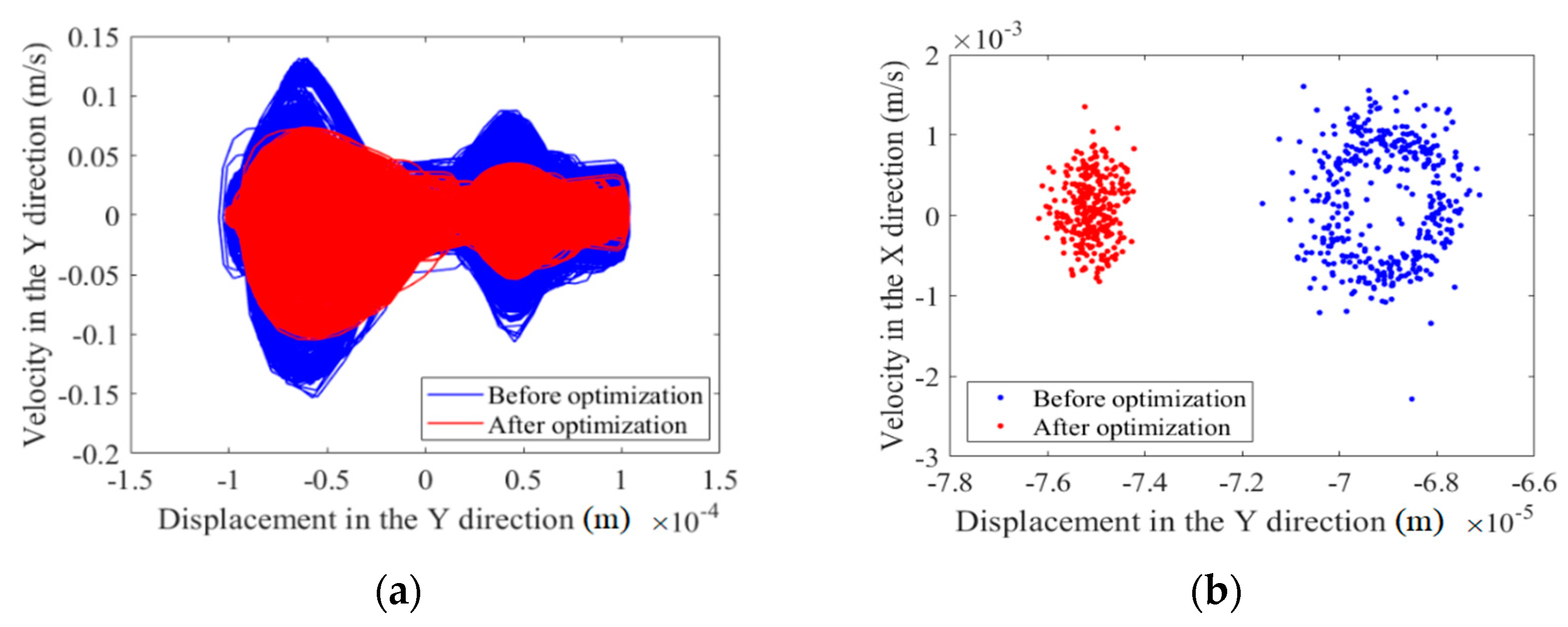
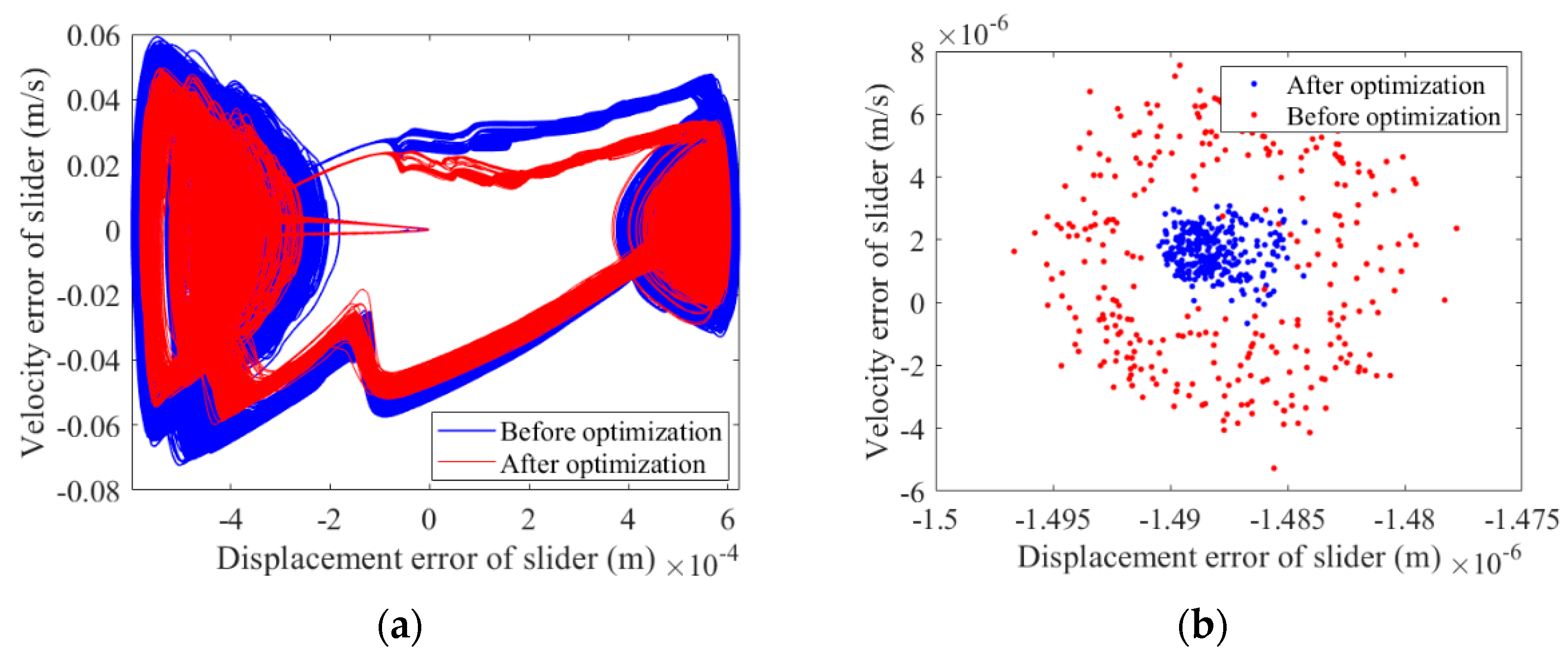
The main aim of this paper is to propose an efficient dynamics optimization method for a planar complex multi-link mechanism including multiple clearances. In this paper, a 2-DOF nine-bar mechanism that can be used as the main transmission mechanism of a hybrid drive multi-link press is taken as the research object. In order to improve the dynamics performance of the mechanism, based on the principle of mass distribution, a dynamics optimization model of a 2-DOF nine-bar mechanism, considering multiple clearances by using a genetic algorithm is proposed. Two optimization criteria are used to minimize the maximum acceleration of the slider and to minimize the difference between the actual central trajectory and the ideal trajectory. Based on the optimization results, the nonlinear characteristics before and after optimization are analyzed via a phase diagram and a Poincaré map. The effect of dynamics optimization on the dynamics accuracy and reliability of the mechanism are also analyzed.
The main structure of this paper is as follows. The clearance model is built in Section 2. The dynamics optimization model of the mechanism, containing clearances, is built in Section 3. The dynamics accuracy and reliability model of the mechanism, including the clearances, is established in Section 4. In Section 5, the effects of optimization on the dynamics responses and dynamics accuracy and reliability of a mechanism with clearances are analyzed. A test platform was built to study the dynamics of the mechanism when incorporating clearances. Our conclusions are presented in Section 6.
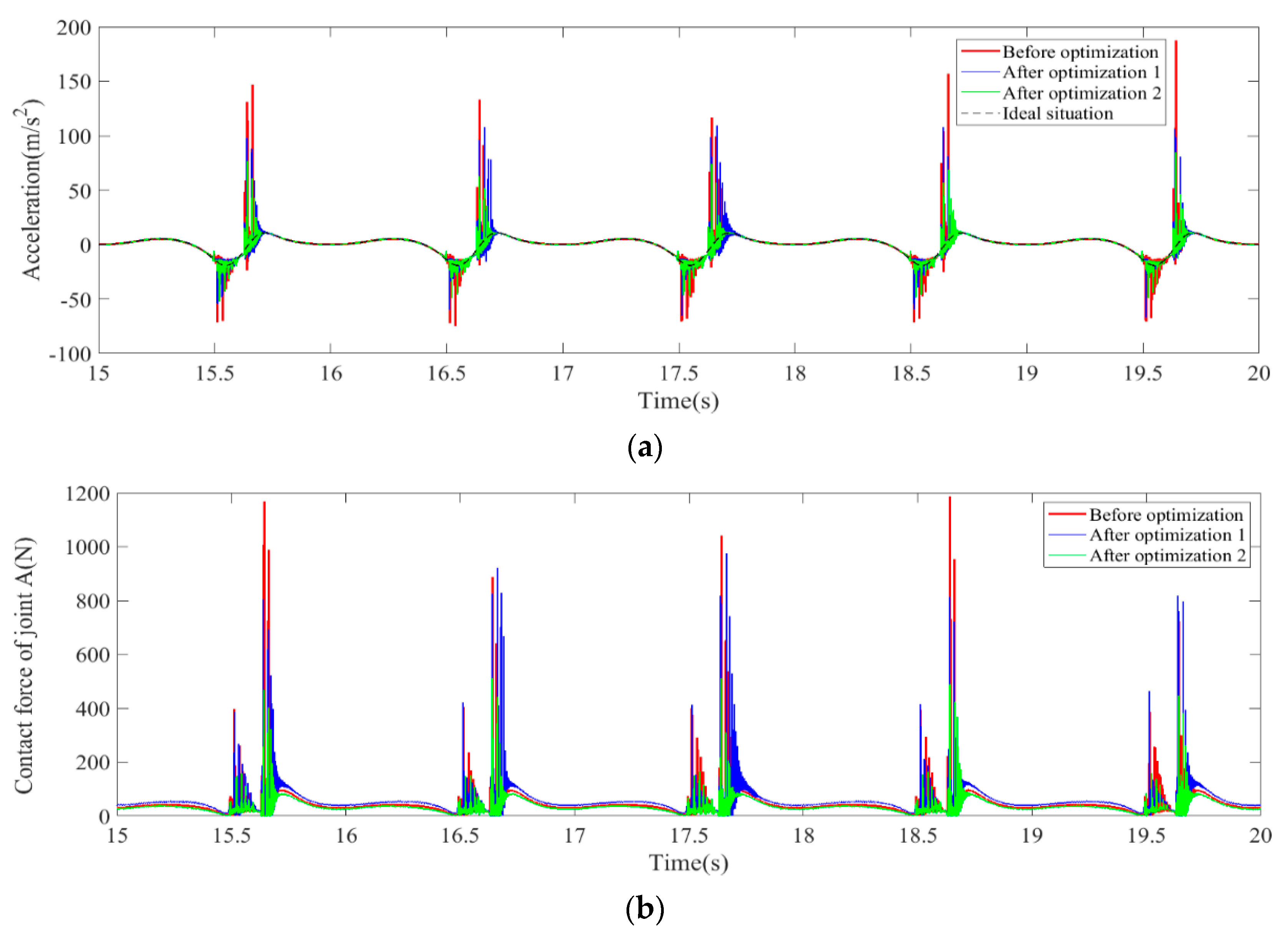
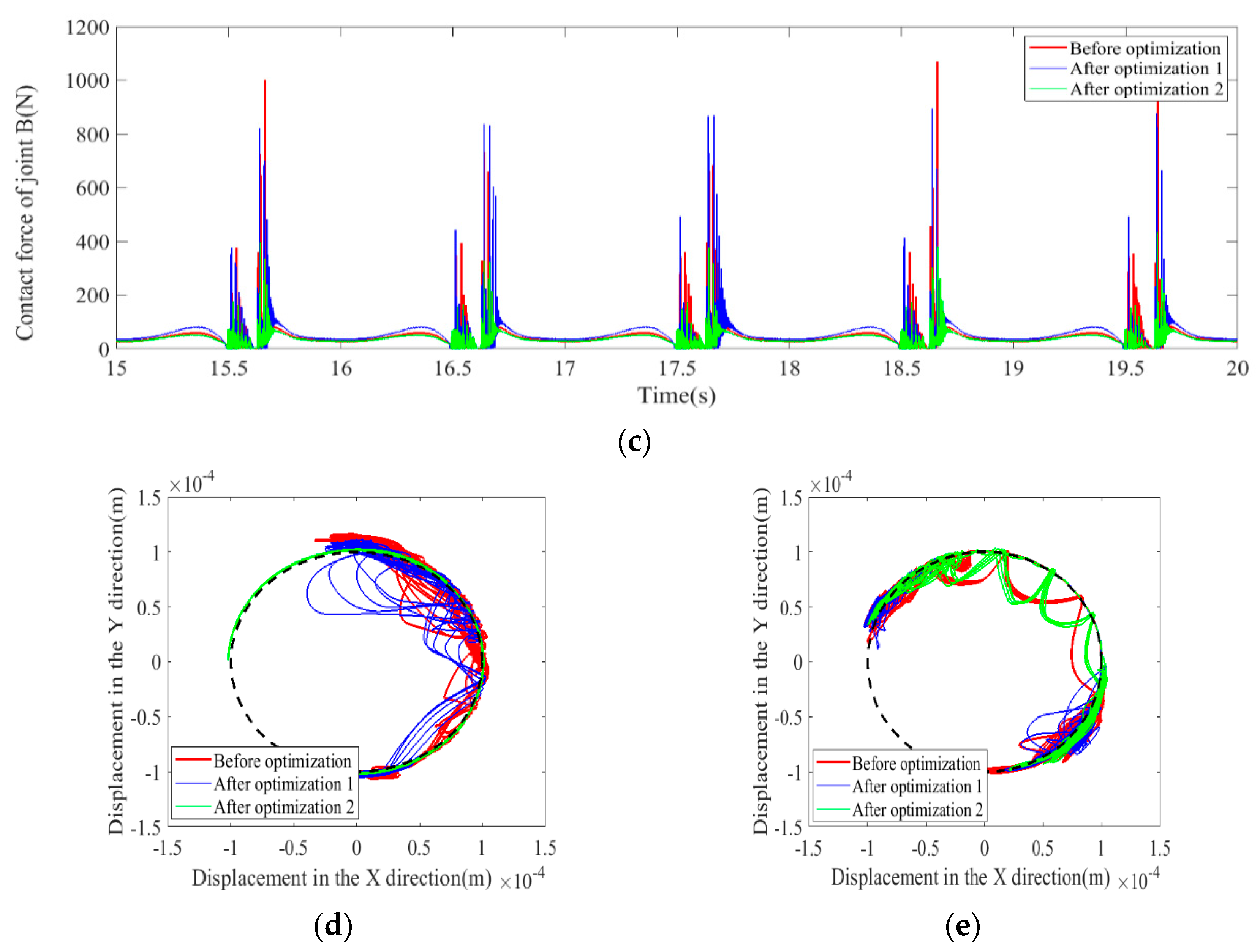
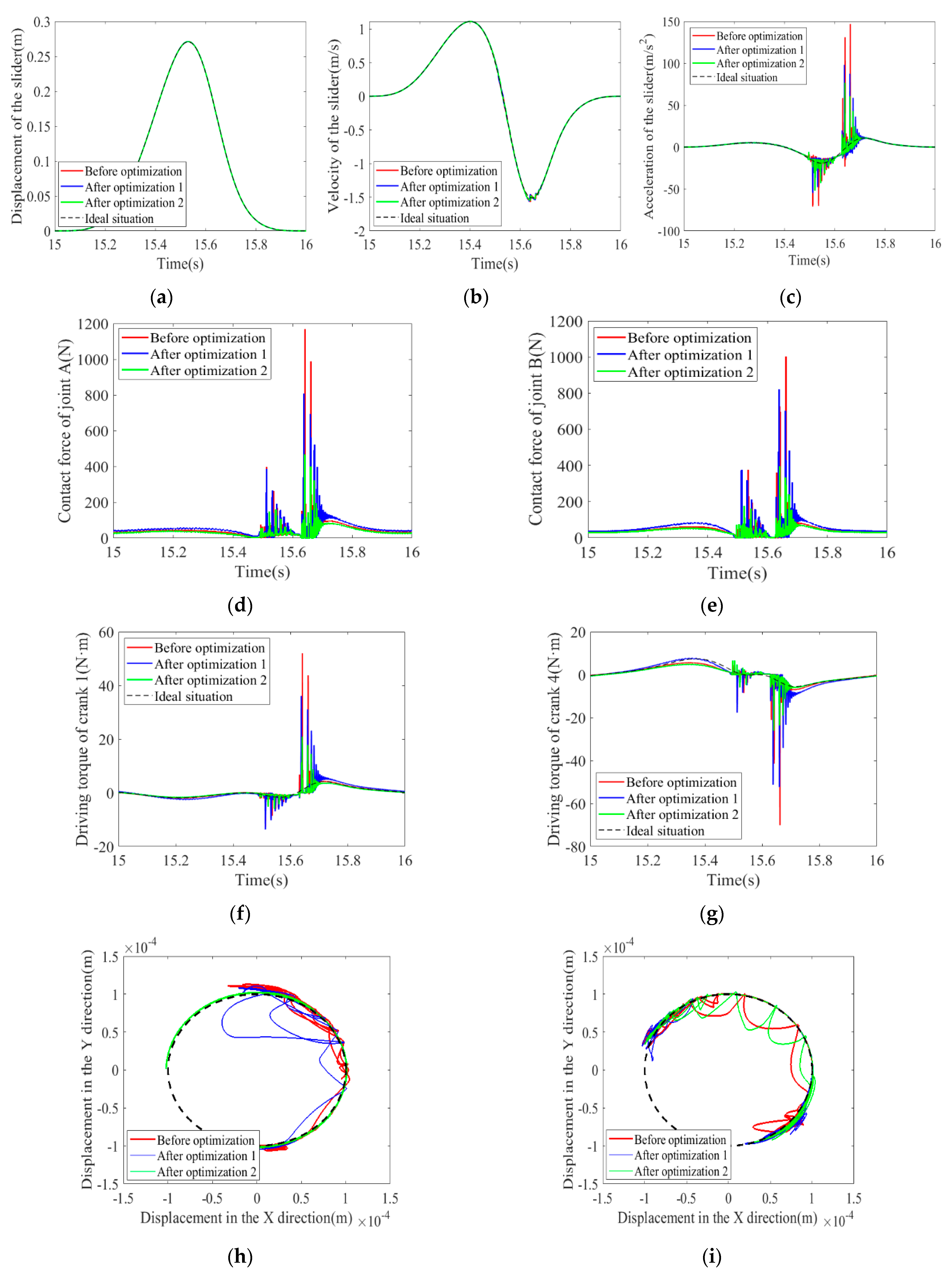
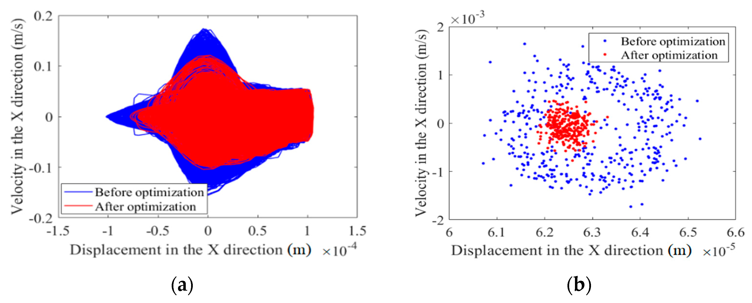
In view of the adverse effect of the clearance of the kinematic pair on the dynamics response of the mechanism, based on the genetic algorithm, this paper proposes two different dynamics optimization modeling methods for a multi-link mechanism with multiple clearances. Two optimization criteria are used to reduce the influence of clearance on the mechanism, which are to minimize the maximum acceleration of the slider as the optimization objective function and to minimize the difference between the actual center trajectory and the ideal trajectory as the optimization’s objective function. According to the optimization results, it was found that when the optimization’s objective function is to minimize the difference between the actual trajectory and ideal trajectory, the optimization effect is stronger than that when the optimization objective function is to minimize the maximum acceleration of the slider. The results show that the peak and vibration frequencies of dynamics response are significantly reduced. Based on the optimization results obtained by taking the minimum difference between the actual center trajectory and the ideal trajectory as the optimization objective, the nonlinear characteristics and dynamics accuracy and reliability before and after optimization were analyzed. The results show that optimization improves the nonlinear characteristics and reliability of the mechanism and also makes the mechanism more stable.

2. Establishment of the Clearance Model

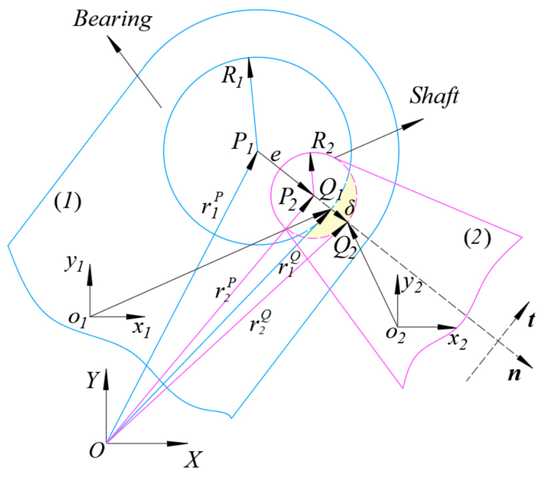
A clearance model of a revolute pair is shown in Figure 1. R1 and R2 are the radii of the bearing and shaft, respectively. The eccentricity vector of dry friction clearance can be written as:
e = r 2 P r 1 P
where r 1 P and r 2 P are the position vectors of the centroid of the shaft and the bearing of the dry friction revolute clearance joint in the fixed coordinate system, respectively.
The unit vector of the eccentric vector is:
n = e e .
The embedding depth of clearance of the rotating pair can be expressed as:
δ = e c
where c is the clearance value, c = R 1 R 2 , e represents the magnitude of eccentricity vector of dry friction revolute clearance joint, and e = e · e .
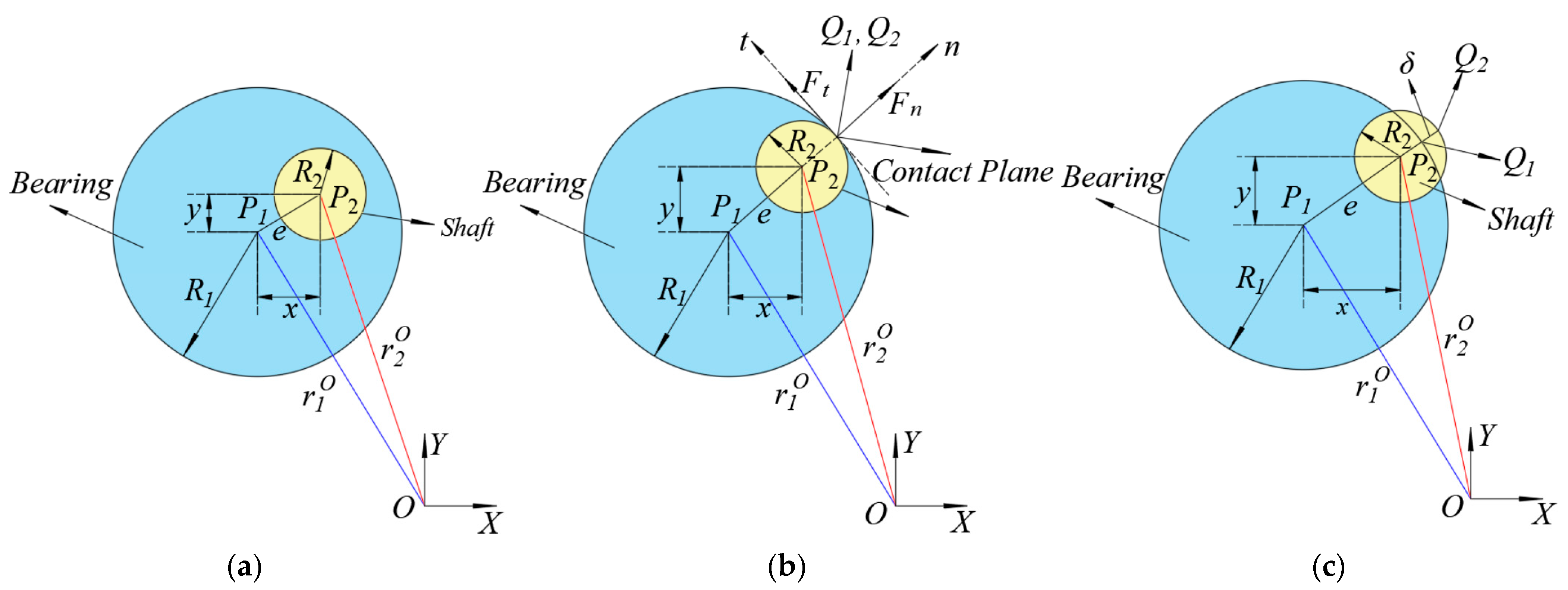
Due to the clearance of the revolute pair, according to the geometric relationship between the bearing and shaft, motion states between the shaft and bearing are divided into the free flight state, continuous contact state, and impact state, as shown in Figure 2.
The criteria for collision between elements in the revolute clearance are as follows:
δ < 0 , f r e e f l i g h t s t a t e δ = 0 , c o n t i n u o u s c o n t a c t s t a t e δ > 0 , i m p a c t s t a t e .
When the embedding depth δ < 0 , there is no collision between the shaft and bearing, and they are in free flight mode, with a contact force F n = 0 . When the embedding depth δ > 0 , the shaft and bearing collide with each other and they are in impact mode, so that the contact force F n 0 . When the embedding depth δ = 0 , the shaft and bearing are in continuous contact mode, with a contact force F n 0 . The change in contact status could be further detected as:
δ t n δ t n + 1 0 .
When δ t n δ t n + 1 0 , δ t n < 0 and δ t n + 1 > 0 , at this moment, the motion state at the clearance joint changes from a free flight state to an impact state. When δ t n δ t n + 1 0 , δ t n > 0 and δ t n + 1 < 0 , at this moment, the motion state at the clearance joint changes from an impact state to a free flight state.
The position vector of the collision point can be expressed as:
r j Q = r j P + R j n j = 1 , 2 .
When the bearing collides with the shaft, the speed at the contact point is:
r ˙ j Q = r ˙ j P + R j n ˙ j = 1 , 2
where n ˙   = e ˙ e e ˙ e e 2 .
The Lankarani–Nikravesh model (L–N model) is a nonlinear viscoelastic model that is suitable for general mechanical contact and collision problems, especially when the coefficient of restitution is high and the energy dissipation in the collision process is relatively small. In addition, the model considers not only energy loss but also the material properties, local elastic deformation, collision speed, and other factors. This model has the advantages of convenient calculation, a fast convergence speed, and so on. It is widely used in the study of the dynamics of mechanisms with clearances [2,18,26,33,34]:
F n = 4 δ n 3 σ 1 + σ 2 R 1 R 2 R 1 + R 2 1 2 1 + 3 1 c e 2 4 δ ˙ δ ˙
where σ 1 = 1 υ 1 2 / E 1 , σ 2 = 1 υ 2 2 / E 2 , υ 1 and υ 2 are the Poisson’s ratio, E 1 and E 2 are the elastic modulus, c e is the recovery coefficient, and δ ˙ is the initial impact velocity. When δ t n δ t n + 1 0 , δ t n < 0 and δ t n + 1 > 0 , the time of collision is between t n and t n + 1 and the impact velocity at time t n + 1 is δ ˙ .
A modified Coulomb friction model is used for tangential friction [2,13,27,35,36]:
F t = c f c d F n v t v t
where c f is the friction coefficient and c d is the dynamics correction coefficient, and c d = 0 , v t < v 0 v t v 0 v 1 v 0 , v 0 v t v 1 1 , v t > v 1 .

3. Dynamics Optimization Model of a Mechanism with Clearances
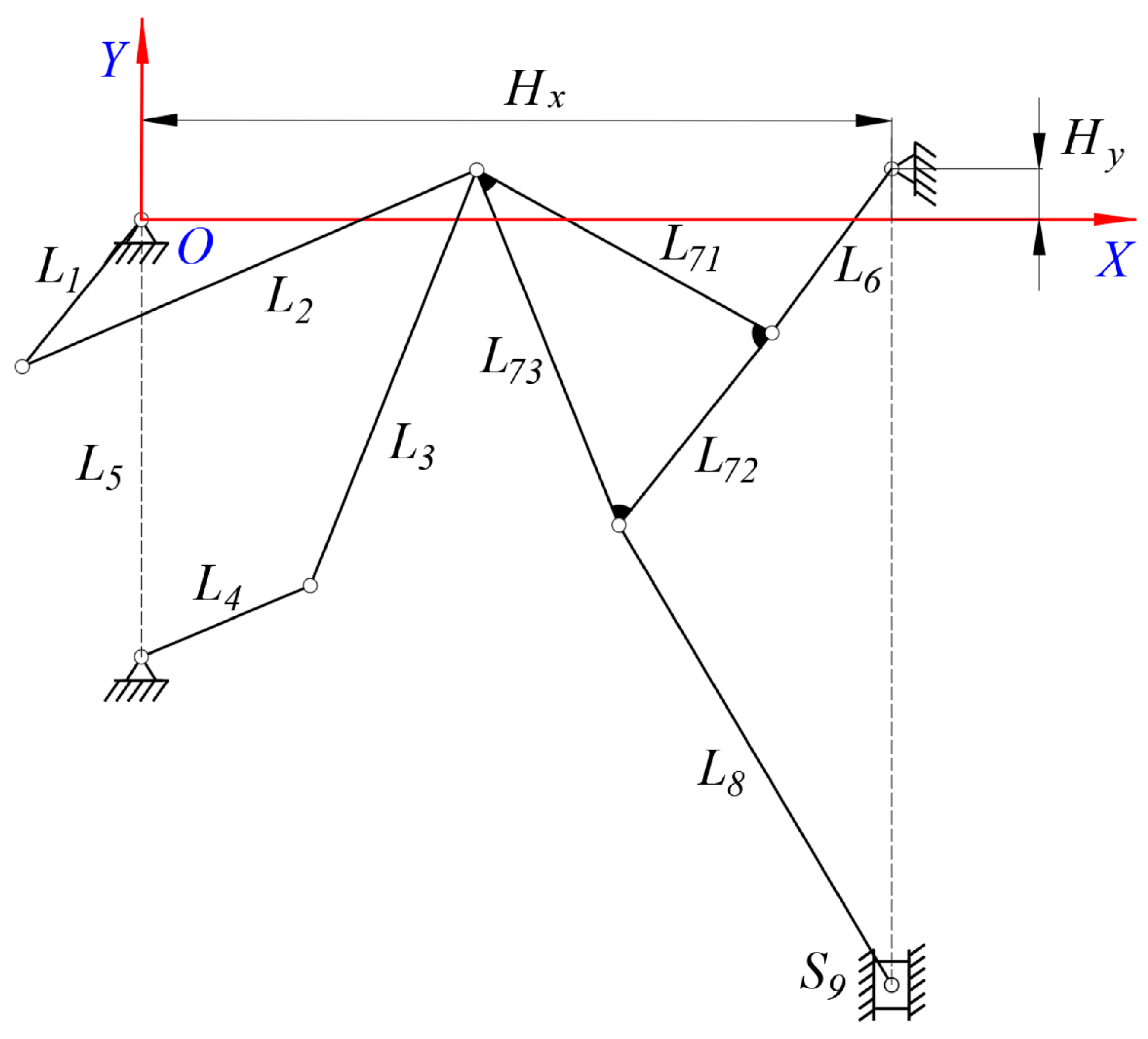
The diagram for a 2-DOF nine–bar mechanism is shown in Figure 3. The 2-DOF nine–bar mechanism is composed of crank 1 (L1), rod 2 (L2), rod 3 (L3), crank 4 (L4), frame 5 (L5), rod 6 (L6), a triangle plate 7 (L71, L72, L73), rod 8 (L8), and a slider (S9). It is known that the mechanism has eight movable members (crank 1, rod 2, rod 3, crank 4, rod 6, triangle plate 7, rod 8, and the slider) and one fixed member (frame 5). The revolute pair and translational pair are lower pairs; the number of lower pairs in this mechanism is 11. According to the calculation formula for the degree of freedom (DOF), the DOF of this mechanism is:
F D O F = 3 n 2 P L P H = 3 × 8 2 × 11 0 = 2
where F D O F is the DOF of the mechanism, n is the total number of moving components of the mechanism, PL is the number of lower pairs, and PH is the number of higher pairs.
It can be seen that the DOF of the mechanism is 2. When the mechanism has two drives, the mechanism has a unique motion; that is, the slider makes a reciprocating linear motion along the guide rail. The 2-DOF nine–bar mechanism has the following positive motion characteristics, such as the low and stable running speed of the slider at the bottom in the dead center, rapid return characteristics, good flexibility, the strong bearing capacity of the mechanism, etc. This 2-DOF nine–bar mechanism could be effective when applied to the main transmission mechanism of a hybrid drive multi–link mechanical press.
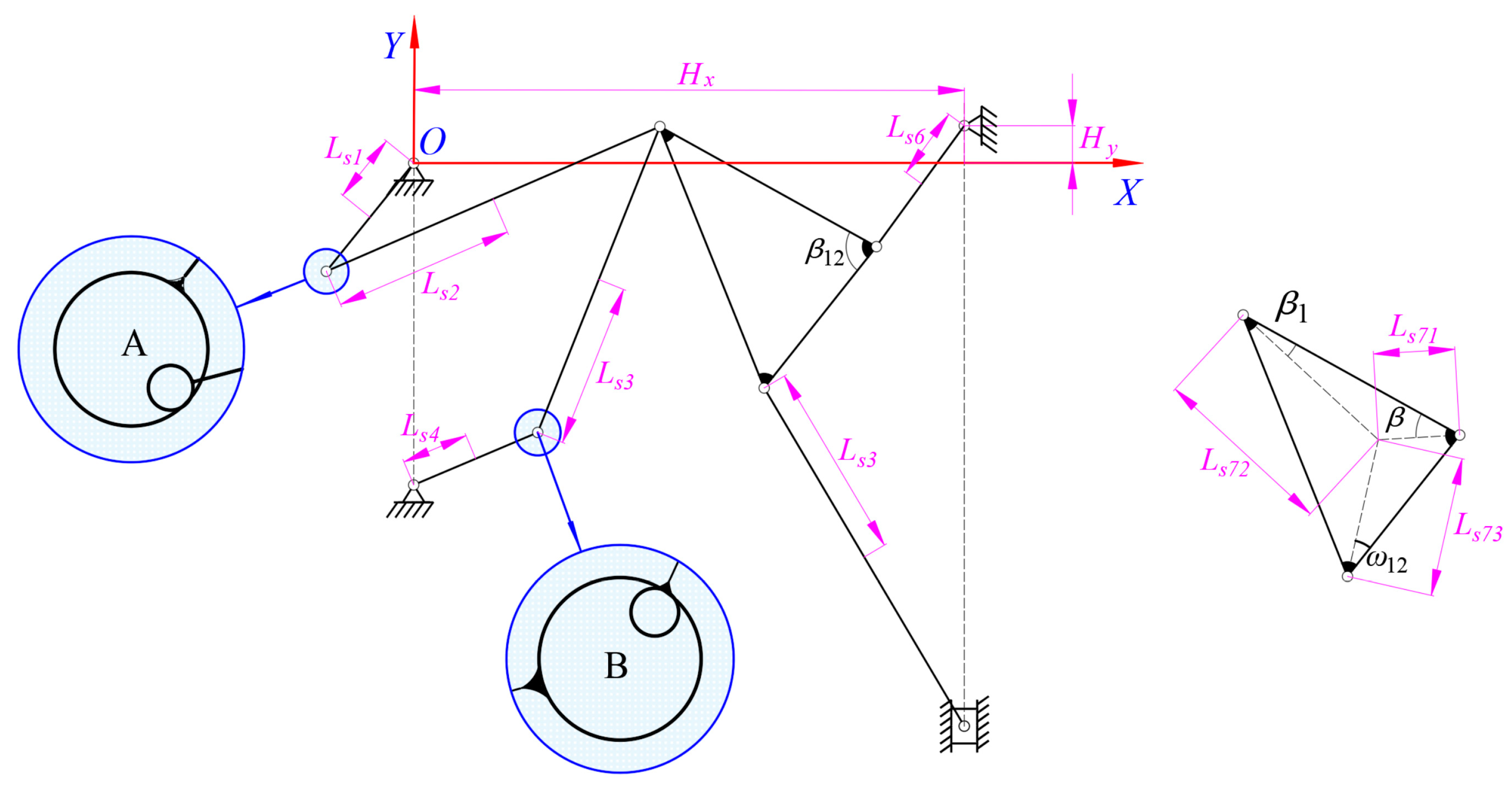
Since the clearance of the revolute pair A is between crank 1 and rod 2, and the clearance of the revolute pair B is between crank 4 and rod 3, the impact forces at clearances A and B directly affect the dynamics of the mechanism. Consequently, this paper focuses on the influence of revolute pair clearances A and B on the mechanism. A structural diagram of the 2-DOF nine-bar mechanism with revolute clearances is shown in Figure 4.

3.1. Design Variable

Since clearances A and B are located on two separate driving components, the end effector directly affects the motion characteristics of the whole mechanism, and the parameters of rod 2, rod 3, and the slider are selected for optimization. Mass, the centroid position, and the moment of inertia are important factors determining the mass distribution of components. Because rods 2 and 3 are long bars, the mass, the center of mass position, and the moment of inertia of the rods will affect the dynamics of the mechanism. Therefore, it is necessary to optimize mass, centroid position, and the moment of inertia of rods 2 and 3. As an end effector, the slider directly affects the motion characteristics of the whole mechanism, so it needs to be optimized. Because the slider moves in translation within the guide rail, its moment of inertia has little effect on the dynamics response of the mechanism. Compared with rods 2 and 3, the length of the slider is relatively short, resulting in the relatively small influence of its center of mass position on the dynamics of the mechanism. Therefore, the quality of the slider is selected as the optimization design variable. To sum up, taking the mass, centroid position, and moment of inertia of rod 2 and rod 3 and the slider’s mass as the optimization design variables:
X c = m 2 , L s 2 , J 2 , m 3 , L s 3 , J 3 , m 9 T = x ( 1 ) , x ( 2 ) , x ( 3 ) , x ( 4 ) , x ( 5 ) , x ( 6 ) , x ( 7 ) T

3.2. Constraint Conditions

The constraints of the dynamics optimization model are:
X c L X c X c U
where XcU and XcL are the upper and lower limits of the optimized design variables. The value ranges of XcU and XcL are shown in Table 1. Among them, the lower limit of component quality is half the size of the original quality, and the upper limit of component quality is twice the size of the original quality. The upper limit and lower limit of the centroid position of the member are taken as the limit positions of the member, respectively. The lower limit of the moment of inertia assumes that the rotating shaft passes through the center of mass of the rod, and the upper limit of the moment of inertia assumes that the rotating shaft passes through the end point of the rod [20,33].

3.3. Objective Functions

3.3.1. Optimize the Maximum Acceleration of the Slider

As the end effector of the 2-DOF nine–bar mechanism, the kinematic characteristics of the slider have important research significance. Acceleration is a bridge connecting kinematics and the dynamics of the mechanism, which is closely related to the force of the system. At the same time, the peak value of the slider’s acceleration intensifies the vibration due to the surge of its clearance value. Therefore, it is of great practical significance to optimize the maximum acceleration of the slider. The objective function of the optimization design is to minimize the maximum value of the slider’s acceleration; the specific expression can be expressed as:
F o = min a H
where a H is the slider’s acceleration. Here, a H = max i a H , which is the maximum of all the absolute values of slider acceleration.

3.3.2. Optimize the Central Trajectory at the Clearance Joint

Due to the existence of clearance, the movement of the clearance shaft in the bearing may be random and arbitrary. Therefore, by optimizing the central trajectory at the clearance point, increasing the continuous contact state between the shaft and bearing, and reducing the generation of the collision state, the undesirable influence of clearance on the mechanism can be reduced effectively.
Taking the minimum difference between the actual center trajectory and the ideal trajectory as the optimization objective, the specific expression of the objective function can be expressed as:
F o = min ω A f A + ω B f B
where ω A and ω B are the weighing factors, and expressions of f A and f B can be written as:
f A = e A x 2 + e A y 2 c A 2 f B = e B x 2 + e B y 2 c B 2
where e A x and e A y are the components of eccentricity between the shaft and bearing in revolute joint A in the X and Y directions, respectively. e B x and e B y are the components of eccentricity between the shaft and bearing in the revolute joint B in the X and Y directions, respectively. c A and c B are the clearance sizes of joints A and B, respectively.
Based on the structural diagram of the mechanism with clearances shown in Figure 1, the expressions of e A x and e A y can be expressed as:
e A = x 2 L s 2 cos θ 2 L 1 cos θ 1 y 2 L s 2 sin θ 2 L 1 sin θ 1 T = e A x e A y T e B = x 3 L s 3 cos θ 3 L 4 cos θ 4 y 3 L s 3 sin θ 3 L 4 sin θ 4 + L 5 T = e B x e B y T

3.3.3. Optimization Method

The genetic algorithm is a multi-objective optimization algorithm that can find an optimal solution by simulating the process of natural evolution. Firstly, the initial population is randomly generated as the candidate solution. Then, according to the fitness value, individuals are selected, crossed, and mutated. The cycle is repeated to obtain a group satisfying the conditions. Finally, the optimal solution of the optimal design variables is obtained.
The steps of the optimization are as follows
(1)
Set the initial parameters: chromosome length, population size, maximum genetic algebra, coding type, mutation probability, crossover probability, etc;
(2)
Randomly generate an initial population with size N, P 0 = x 1 0 , x 2 0 , , x N 1 0 , x N 0 ;
(3)
Calculate the fitness value of each individual x i t ( i = 1 , 2 , , N ) in the population P t = x 1 t , x 2 t , , x N 1 t , x N t ;
(4)
By comparing the fitness value of each individual, select individuals according to the selection operator, and keep the selected individuals with a larger fitness value until the number of the population is N;
(5)
Optimize the combination of some genes of the surviving parent individuals, exchanging the genes at some corresponding positions of the two parent individuals according to the crossover probability, so as to produce two new individuals; the individuals that have not been crossed directly replicate into the new species group;
(6)
The genes at some coding positions are mutated according to the mutation probability. The mutated individual replaces the original individual in the new species group. Individuals without compilation directly enter the new population. This completes an evolutionary process and selects the next generation of the population P t + 1 = x 1 t + 1 , x 2 t + 1 , , x N 1 t + 1 , x N t + 1 ;
(7)
If the fitness has reached saturation or the number of iterations has reached the upper limit, it will stop. Otherwise, go to step 3.

3.4. Establishment of a Dynamics Optimization Model of a 2-DOF Nine-Bar Mechanism with Multiple Clearances

The generalized coordinates of each component are set as:
q i = x i y i θ i T  
where x i and y i are the position components of component i in the X and Y directions in the system coordinate system, and θ i is the rotation angle of member i.
The 2-DOF nine-bar mechanism has 24 generalized coordinates; the generalized coordinates of the mechanism can be expressed as:
q = x 1 y 1 θ 1 x 2 y 2 θ 2 x 3 y 3 θ 3 x 4 y 4 θ 4 x 6 y 6 θ 6 x 7 y 7 θ 7 x 8 y 8 θ 8 x 9 y 9 θ 9 T
The dynamics optimization model of the mechanism with clearances is the set of the dynamics model and the optimization design variables. A displacement constraint equation with multiple clearances, including optimization design variables, could be written as:
Φ ( q , t ) = ( x 1 L s 1 cos θ 1 y 1 L s 1 sin θ 1 x 4 L s 4 cos θ 4 y 4 L s 4 sin θ 4 + L 5 x 7 + L s 72 cos ( α 1 ) x 2 ( L 2 x ( 2 ) ) cos θ 2 y 7 + L s 72 sin ( α 1 ) y 2 ( L 2 x ( 2 ) ) sin θ 2 x 7 + L s 72 cos ( α 1 ) x 3 ( L 3 x ( 5 ) ) cos θ 3 y 7 + L s 72 sin ( α 1 ) y 3 ( L 3 x ( 5 ) ) sin θ 3 x 6 L s 6 cos θ 6 H x y 6 L s 6 sin θ 6 H y x 7 L s 71 cos ( α 2 ) x 6 L s 6 cos θ 6 y 7 L s 71 sin ( α 2 ) y 6 L s 6 sin θ 6 x 7 + L s 73 cos ( α 3 ) x 8 + L s 8 cos θ 8 y 7 + L s 73 sin ( α 3 ) y 8 + L s 8 sin θ 8 x 9 H x L 6 cos θ 6 L 72 cos ( α 4 ) L s 8 cos θ 8 y 9 H y L 6 sin θ 6 L 72 sin ( α 4 ) L s 8 sin θ 8 x 9 H x θ 9 1.5 π θ 1 ω 1 t 5.7645 θ 4 ω 4 t + 2.4934 ) = 0
where the values of β, β1, β12, and ω12 are 34.11°, 22.22°, 83.24°, and 36.19°, respectively. Hx and Hy are 0.08 m and 0.645 m, respectively. α 1 = θ 7 β 1 , α 2 = θ 7 + β , α 3 = θ 7 + β 12 + ω 12 , α 4 = θ 7 + β 12 .
Velocity is a constraint equation that can be expressed as [37]:
Φ q q ˙ = Φ t υ
where Φ q is the Jacobian matrix, Φ q = Φ / q , q ˙ represents the generalized velocity vector, Φ t = Φ / t , and Φ t can be written as
Φ t = Φ t = 0 1 × 18 , ω 1 , ω 4 T
The Jacobian matrix of the mechanism can be expressed as:
Φ q = Φ q ( 1 ) , Φ q ( 2 ) , Φ q ( 3 ) , , Φ q ( 22 ) , Φ q ( 23 ) , Φ q ( 24 )
where Φ q ( 1 ) = 1 , 0 19 × 1 T , Φ q ( 2 ) = 0 , 1 , 0 18 × 1 T , Φ q ( 3 ) = L s 1 sin θ 1 , L s 1 cos θ 1 , 0 16 × 1 , 1 , 0 T , Φ q ( 4 ) = 0 4 × 1 , - 1 , 0 15 × 1 T , Φ q ( 5 ) = 0 5 × 1 , - 1 , 0 14 × 1 T , Φ q ( 6 ) = 0 4 × 1 , L s 2 sin θ 2 , L s 1 cos θ 2 , 0 14 × 1 T , Φ q ( 7 ) = 0 6 × 1 , - 1 , 0 13 × 1 T , Φ q ( 8 ) = 0 7 × 1 , - 1 , 0 12 × 1 T , Φ q ( 9 ) = 0 6 × 1 , L s 3 sin θ 3 , L s 3 cos θ 3 , 0 12 × 1 T , Φ q ( 10 ) = 0 2 × 1 , 1 , 0 17 × 1 T , Φ q ( 11 ) = 0 3 × 1 , 1 , 0 16 × 1 T , Φ q ( 12 ) = 0 2 × 1 , L s 4 sin θ 4 , L s 4 cos θ 4 , 0 15 × 1 , 1 T , Φ q ( 13 ) = 0 8 × 1 , 1 , 0 , 1 , 0 9 × 1 T , Φ q ( 14 ) = 0 9 × 1 , 1 , 0 , 1 , 0 8 × 1 T , Φ q ( 15 ) = 0 8 × 1 , L s 6 sin θ 6 , L s 6 cos θ 6 , L s 6 sin θ 6 , L s 6 cos θ 6 , 0 2 × 1 , L s 6 sin θ 6 , L s 6 cos θ 6 , 0 4 × 1 T , Φ q ( 16 ) = 0 4 × 1 , 1 , 0 , 1 , 0 3 × 1 , 1 , 0 , 1 , 0 7 × 1 T , Φ q ( 17 ) = 0 5 × 1 , 1 , 0 , 1 , 0 3 × 1 , 1 , 0 , 1 , 0 6 × 1 T , Φ q ( 18 ) = 0 4 × 1 , L s 72 sin α 1 , L s 72 cos α 1 , L s 72 sin α 1 , L s 72 cos α 1 , 0 2 × 1 , L s 71 sin α 2 , L s 71 cos α 2 , L s 73 sin α 3 , L s 73 cos α 3 , L 72 sin α 4 , L 72 cos α 4 , 0 4 × 1 T , Φ q ( 19 ) = 0 12 × 1 , 1 , 0 7 × 1 T , Φ q ( 20 ) = 0 13 × 1 , 1 , 0 6 × 1 T , Φ q ( 21 ) = 0 12 × 1 , L s 8 sin θ 8 , L s 8 cos θ 8 , L s 8 sin θ 8 , L s 8 cos θ 8 , 0 4 × 1 T , Φ q ( 22 ) = 0 14 × 1 , 1 , 0 , 1 , 0 3 × 1 T , Φ q ( 23 ) = 0 15 × 1 , 1 , 0 4 × 1 T , Φ q ( 24 ) = 0 17 × 1 , 1 , 0 2 × 1 T .
The acceleration constraint equations could be expressed as [37]:
Φ q q ¨ = Φ q q ˙ q q ˙ 2 Φ q t q ˙ Φ t t γ
where q ¨ represents the generalized acceleration vector, Φ q t is the partial derivative of the Jacobian matrix with respect to time, Φ q t = 0 20 × 24 , Φ t t is the partial derivative of Φ t with respect to time, Φ t t = 0 20 × 1 , and γ is the vector of quadratic velocity terms.
Φ q q can be written as:
Φ q q = Φ q ( 1 ) q ( 1 ) , Φ q ( 2 ) q ( 2 ) , Φ q ( 3 ) q ( 3 ) , , Φ q ( 22 ) q ( 22 ) , Φ q ( 23 ) q ( 23 ) , Φ q ( 24 ) q ( 24 )
where: Φ q ( 1 ) q ( 1 ) = Φ q ( 2 ) q ( 2 ) = Φ q ( 4 ) q ( 4 ) = Φ q ( 5 ) q ( 5 ) = Φ q ( 7 ) q ( 7 ) = Φ q ( 8 ) q ( 8 ) = Φ q ( 10 ) q ( 10 ) = Φ q ( 11 ) q ( 11 ) = Φ q ( 13 ) q ( 13 ) = Φ q ( 14 ) q ( 14 ) = Φ q ( 16 ) q ( 16 ) = Φ q ( 17 ) q ( 17 ) = Φ q ( 19 ) q ( 19 ) = Φ q ( 20 ) q ( 20 ) = Φ q ( 22 ) q ( 22 ) = Φ q ( 23 ) q ( 23 ) = Φ q ( 24 ) q ( 24 ) = 0 1 × 20 , Φ q ( 3 ) q ( 3 ) = L s 1 ω 1 cos θ 1 , L s 1 ω 1 sin θ 1 , 0 18 × 1 T , Φ q ( 6 ) q ( 6 ) = 0 4 × 1 , L s 2 ω 2 cos θ 2 , L s 1 ω 2 sin θ 2 , 0 14 × 1 T , Φ q ( 9 ) q ( 9 ) = 0 6 × 1 , L s 3 ω 3 cos θ 3 , L s 3 ω 3 sin θ 3 , 0 12 × 1 T , Φ q ( 12 ) q ( 12 ) = 0 2 × 1 , L s 4 ω 4 cos θ 4 , L s 4 ω 4 sin θ 4 , 0 16 × 1 T , Φ q ( 15 ) q ( 15 ) = 0 8 × 1 , L s 6 ω 6 cos θ 6 , L s 6 ω 6 sin θ 6 , L s 6 ω 6 cos θ 6 , L s 6 ω 6 sin θ 6 , 0 3 × 1 , L s 6 ω 6 cos θ 6 , L s 6 ω 6 sin θ 6 , 0 4 × 1 T , Φ q ( 18 ) q ( 18 ) = 0 4 × 1 , L s 72 ω 7 cos α 1 , L s 72 ω 7 sin α 1 , L s 72 ω 7 cos α 1 , L s 72 ω 7 sin α 1 , 0 2 × 1 , L s 71 ω 7 cos α 2 , L s 71 ω 7 sin α 2 , L s 73 ω 7 cos α 3 , L s 73 ω 7 sin α 3 , L 72 ω 7 cos α 4 , L 72 ω 7 sin α 4 , 0 4 × 1 T , Φ q ( 21 ) q ( 21 ) = 0 12 × 1 , L s 8 ω 8 cos θ 8 , L s 8 ω 8 sin θ 8 , L s 8 ω 8 cos θ 8 , L s 8 ω 8 sin θ 8 , 0 4 × 1 T .
The system dynamics equation considering optimal design variables can be expressed as follows [38]:
M q ¨ + Φ q T λ = g
where M is the mass matrix of the system, λ is the Lagrange multiplier, and g is the generalized force of the system, including gravity, external force, and external torque.
A quality matrix considering the optimal design variables of a 2-DOF nine–bar mechanism with clearances can be expressed as:
M = diag m 1   m 1   J 1   x ( 1 )   x ( 1 )   x ( 3 )   x ( 4 )   x ( 4 )   x ( 6 )   m 4   m 4   J 4   m 6   m 6   J 6   m 7   m 7   J 7   m 8   m 8   J 8   x ( 7 )   x ( 7 )   J 9 .
The generalized force of a system with optimal design variables can be expressed as:
g = F x A ,   F y A ,   M A 1 ,   - F x A ,   - F y A ,   M A 2 ,   F x B ,   F y B ,   M B 1 ,   - F x B ,   - F y B ,   M B 2 ,   0 ,   0 ,   0 ,   0 ,   0 ,   0 ,   0 ,   0 ,   0 ,   0 ,   0 ,   0
M A 1 = O Q 1 y y 1 F A x + O Q 1 x x 1 F A y M A 2 = O Q 2 y y 2 F A x + O Q 2 x x 2 F A y M B 1 = O Q 4 y y 4 F B x + O Q 4 x x 4 F B y M B 2 = O Q 3 y y 3 F B x + O Q 3 x x 3 F B y
where F i j (i = A, B; j = X, Y) are the components of contact force in the j directions at clearance joint i, respectively. Q 1 and Q 2 are the collision points of the bearing and shaft in rotating pair A, respectively. Q 3 and Q 4 are the collision points of the bearing and shaft in rotating pair B, respectively:
O Q 1 = O P 1 + R 1 n A O Q 2 = O P 2 + R 2 n A O Q 3 = O P 3 + R 2 n B O Q 4 = O P 4 + R 1 n B
where n A and n B are unit normal vectors of clearances A and B, respectively. P 1 and P 2 are the center points of the bearing and shaft in revolute A, respectively. P 3 and P 4 are the center points of the bearing and shaft in revolute A, respectively:
O P 1 = L 1 cos θ 1 L 1 sin θ 1 O P 2 = x 2 x ( 2 ) cos θ 2 y 2 x ( 2 ) sin θ 2 O P 3 = x 3 x ( 5 ) cos θ 3 y 3 x ( 5 ) sin θ 3 O P 4 = L 4 cos θ 4 L 4 sin θ 4 L 5 .
The dynamics equation of the mechanism can be obtained by solving Equations (23) and (25), and the equation expression is as follows:
M Φ q T Φ q 0 q ¨ λ = g γ .
In order to overcome the default of the dynamics equation, based on the Baumgarte default stability algorithm, a strong nonlinear equation with optimal design variables is solved [39,40,41]:
M Φ q T Φ q 0 q ¨ λ = g γ 2 α Φ ˙ β 2 Φ
where α and β are the correction parameters, and Φ ˙ = d Φ d t .
Because the dynamics equation of the mechanism containing the clearances is a very nonlinear equation, it is difficult to solve the equation stably. Variable-order numerical differentiation algorithms (NDFs) are used to solve the dynamics equations, while the high-order equations are transformed into low-order equations. Therefore, the ode15s function in MATLAB is used to solve Equation (32) and convert the second-order differential equation into a first-order differential equation:
d q ˙ 1 d t = g 1 , d q 1 d t = q ˙ 1 d q ˙ 2 d t = g 2 , d q 2 d t = q ˙ 2 d q ˙ i d t = g i , d q i d t = q ˙ i
where q i represents the generalized coordinates and i is the number of generalized coordinates.

4. Establishment of a Dynamics Accuracy and Reliability Model

It is assumed that the error function of the mechanism is h(x, t) = PP′, where P is the actual situation of the dynamics c response of the mechanism, and P’ is the ideal situation of the dynamics response of the mechanism. According to the error characteristics of random variables, while h x , t ε , the mechanism is reliable; if not, the mechanism fails.
For mechanism reliability, the actual error is stress, and the allowable error is strength. Assuming that these are the actual and allowable errors of the motion characteristics, where driving torque meets a normal distribution, the reliability of the mechanism can be solved according to the stress-strength interference theory. Based upon the stress-strength interference theory, reliability is defined as the probability that strength is greater than stress [27]:
R = P S S ˜ > 0 = P Z > 0
where Z is the safety margin.
It is assumed that stress and strength obey a normal distribution, and the safety margin also obeys normal distribution:
f Z = 1 2 π σ Z e 1 2 Z μ Z σ Z 2
where μ Z = μ S μ S ˜ , σ Z = σ S 2 + σ S ˜ 2 , μ S and σ S are the mean value and variance of intensity, and μ S ˜ and σ S ˜ are the mean value and the variance of stress.
Reliability could be written as:
P Z > 0 = 0 1 2 π σ Z e 1 2 Z μ Z σ Z 2 d Z = z 0 φ z d z = 1 Φ z 0
where φ z = 1 2 π e 1 2 z 2 , z = Z μ Z σ Z , and z 0 = μ Z σ Z = μ S μ S ˜ σ S 2 + σ S ˜ 2 1 2 .
The reliability index can be expressed as:
β = μ Z σ Z = μ S μ S ˜ σ S 2 + σ S ˜ 2 .

5. Effect of Optimization on the Dynamics Responses and the Dynamics Accuracy and Reliability of a Mechanism with Clearances

5.1. Simulation Parameters

The mass, moment of inertia, geometric parameters, and clearance parameters are shown in Table 2 and Table 3.
In order to exaggerate the influence of the clearance parameters on the dynamics response of the mechanism, the clearance value at revolute pairs A and B is set as 0.1 mm, and the friction coefficient at the clearance is set as 0.01, which will lead to a sharp increase in the peak value of the dynamics response.
When the optimization objective is to minimize the maximum acceleration of the slider, rod 2, rod 3, and the slider are optimized according to the principle of mass distribution. The optimization results are as follows:
m 2 = 1.574   ( kg ) L s 2 = 0.241   ( m ) J 2 = 0.007   ( kg m 2 ) m 3 = 1.12   ( kg ) L s 3 = 0.235   ( m ) J 3 = 0.033   ( kg m 2 ) m 9 = 1.574   ( kg ) .
When the optimization objective is to minimize the difference between the actual center trajectory and the ideal trajectory, the optimization results are as follows:
m 2 = 0.538   ( kg ) L s 2 = 0.244   ( m ) J 2 = 0.004   ( kg m 2 ) m 3 = 0.862   ( kg ) L s 3 = 0.319   ( m ) J 3 = 0.006   ( kg m 2 ) m 9 = 0.4   ( kg ) .

5.2. Comparative Analysis of Dynamics Behavior before and after Optimization

5.2.1. Comparative Analysis of Dynamics Response of the Mechanism before and after Optimization

Based on Equations (26) and (27), the dynamics response of the mechanism after stabilization is shown in Figure 5. When the optimization’s objective function is to minimize the maximum acceleration of the slider, it is characterized by a blue line in Figure 5 and is named “Optimization 1”. When the optimization objective function is to minimize the difference between the actual trajectory and ideal trajectory, it is characterized by a green line in Figure 4 and is named “Optimization 2”.
According to the acceleration curve, there are two optimization methods that can both effectively reduce the peak value of acceleration. It shows that the two methods have a good effect on improving the slider’s acceleration, but the optimization effect in “Optimization 2” is better than that of “Optimization 1”. Similarly, it can be seen from the contact force at the clearance joint and center trajectory diagram that when “Optimization 2” is adopted, the optimization effect is significant, and the times of peak and large amplitude of the dynamics are significantly reduced. However, when “Optimization 1” is adopted, the peak value of the contact force at the clearance joint is sometimes smaller than it was before optimization, and sometimes increases sharply. To sum up, when the objective function of optimization is to minimize the difference between the actual trajectory and the ideal trajectory, the optimization effect is stronger than that when the optimization objective function is to minimize the maximum acceleration of the slider.
One of the cycles of data is selected for analysis, and the effects of the different optimization objective functions on the dynamics responses of the mechanism are analyzed numerically. The diagram for the dynamics response is shown in Figure 6. It can be seen from the diagram that clearances have little effect on displacement and velocity, which is almost close to an ideal state. When the mechanism has not been optimized, the peak value of the acceleration of the slider, the contact force of joint A, the contact force of joint B, the driving torque of crank 1, and the driving torque of crank 4 are 146.9 m/s2, 1157 N, 1001 N, −70.09 N·m, and 52 N·m, respectively. When the objective function of optimization is to minimize the maximum acceleration of the slider, the corresponding peak values are 98.13 m/s2, 806 N, 820.2 N, −52.29 N·m, and 36.11 N·m, respectively. When the objective function of optimization is to minimize the difference between the actual trajectory and ideal trajectory, the corresponding peak values are 76.81 m/s2, 469.4 N, 395.7 N, −26.11 N·m, and 20.95 N·m, respectively. When the objective function of optimization is to minimize the maximum acceleration of the slider, the optimization efficiencies are 33.20%, 30.34%, 18.06%, 25.40%, and 30.56%, respectively. When the objective function of optimization is to minimize the difference between the actual trajectory and ideal trajectory, the corresponding optimization efficiencies are 47.71%, 59.43%, 60.47%, 62.75%, and 59.71%, respectively. It can be seen that the optimization effect of “Optimization 2” is significantly better than that of “Optimization 1”.

5.2.2. Comparative Analysis of the Nonlinear Characteristics of the Mechanism before and after Optimization

Based on the optimization data obtained by optimizing the central trajectory at the clearance joints, the nonlinear characteristics of the clearance before and after optimization are analyzed. When the mechanism runs for 500 cycles, the nonlinear characteristics of a mechanism containing clearances before and after optimization are analyzed with a phase map and Poincaré map. The nonlinear characteristics of joints A and B are shown in Figure 7, Figure 8, Figure 9 and Figure 10. The nonlinear characteristics of the slider’s error are shown in Figure 11.
It can be seen from the phase diagrams and Poincaré maps that the area of the phase diagram after optimization decreases; the dispersion of mapping points after optimization weakens and becomes relatively concentrated. It can be seen that clearance optimization can effectively improve both the chaos and the stability of the mechanism.

5.3. Dynamics Accuracy and Reliability Analysis of a Mechanism with Clearances before and after Optimization

Based on the data yielded after optimization (where the optimization objective is to minimize the difference between the actual trajectory and ideal trajectory), the dynamics accuracy and reliability of the mechanism before and after optimization are compared and analyzed. The reliability index diagrams of displacement, velocity, acceleration, torque 1, and torque 4 are shown in Figure 12.
Because the clearance of the kinematic pair has little effect on the slider’s displacement, the change in the reliability index of the slider’s displacement is not obvious, but the reliability of the slider’s displacement has been improved after optimization. The sensitivity of the slider’s velocity to the clearance is stronger than that of the slider’s displacement, so the reliability index of velocity is significantly improved. The sensitivity of the slider’s acceleration and the driving torque to clearance are strong, dynamical response curves with an obvious vibration and peak, and the response curves have been significantly improved after optimization. Therefore, the reliability indexes of acceleration and torque are obviously larger. In general, optimization enhances the reliability of the mechanism, and the mechanism becomes more stable.

5.4. Experimental Research into a Mechanism with Clearances

Design of the Test Platform for a Mechanism with Clearances
The 2-DOF nine–bar mechanism test bed is shown in Figure 13. The structural diagram of the 2-DOF nine–bar mechanism test platform is shown in Figure 14. The two motors are installed under the support plate, and the two cranks are driven by motors to drive the slider to move back and forth along the guide rail. The clearances between the two cranks and connecting rods are considered (revolute clearances A and B). The component is made of aluminum alloy, the elastic model is 70 Gpa, the bearing radius is 12 mm, and pin shafts with a clearance value of 0.1 mm are shown in Figure 15. In order to facilitate the processing and installation of parts, we have modified the dimensions to some extent. However, the theoretical results shown in Figure 16b are based on the theoretical model proposed in this paper. The geometric and inertial parameters of the test platform are shown in Table 4.
When the operating speeds of Crank 1 and Crank 4 are 60 rpm and −60 rpm, respectively, the comparison between the experimental results and theoretical results is shown in Figure 16. According to Figure 16a, the peak value of acceleration corresponding to the experimental results is 50.36 m/s2. According to Figure 16b, the peak value of acceleration corresponding to the theoretical calculation results is 65.43 m/s2. As shown in Figure 16c, it can be seen from the figure that the two curves are basically consistent in trend, but there is a certain difference in value. The comparison between the theoretical and experimental numerical results of the maximum acceleration is shown in Table 5. According to the data in Table 5, the error between the theoretical result and the experimental result is 15.07 m/s2, and the error rate is 23.03%. The main reason is that the vibration of the mechanism and the friction of the components lead to a decrease in the peak value of the experimental results and the acceleration of the vibration frequency. This can basically verify the correctness of the theoretical results.

6. Conclusions

The dynamics optimization research and dynamics accuracy and reliability analysis of a complex multi-link mechanism containing clearances are researched in this paper.
(1) The dynamics optimization model and dynamics accuracy and reliability model of a mechanism are built, considering the clearances.
(2) The effects of two different optimization objective functions on the dynamics optimization of a mechanism with clearances are compared and analyzed, and the effects on dynamics responses and the nonlinear characteristics of the mechanism before and after optimization are analyzed. It is found that optimization effectively improves the dynamics performance of the mechanism considering clearances; it weakens the mechanism’s chaos phenomena and improves the mechanism’s stability.
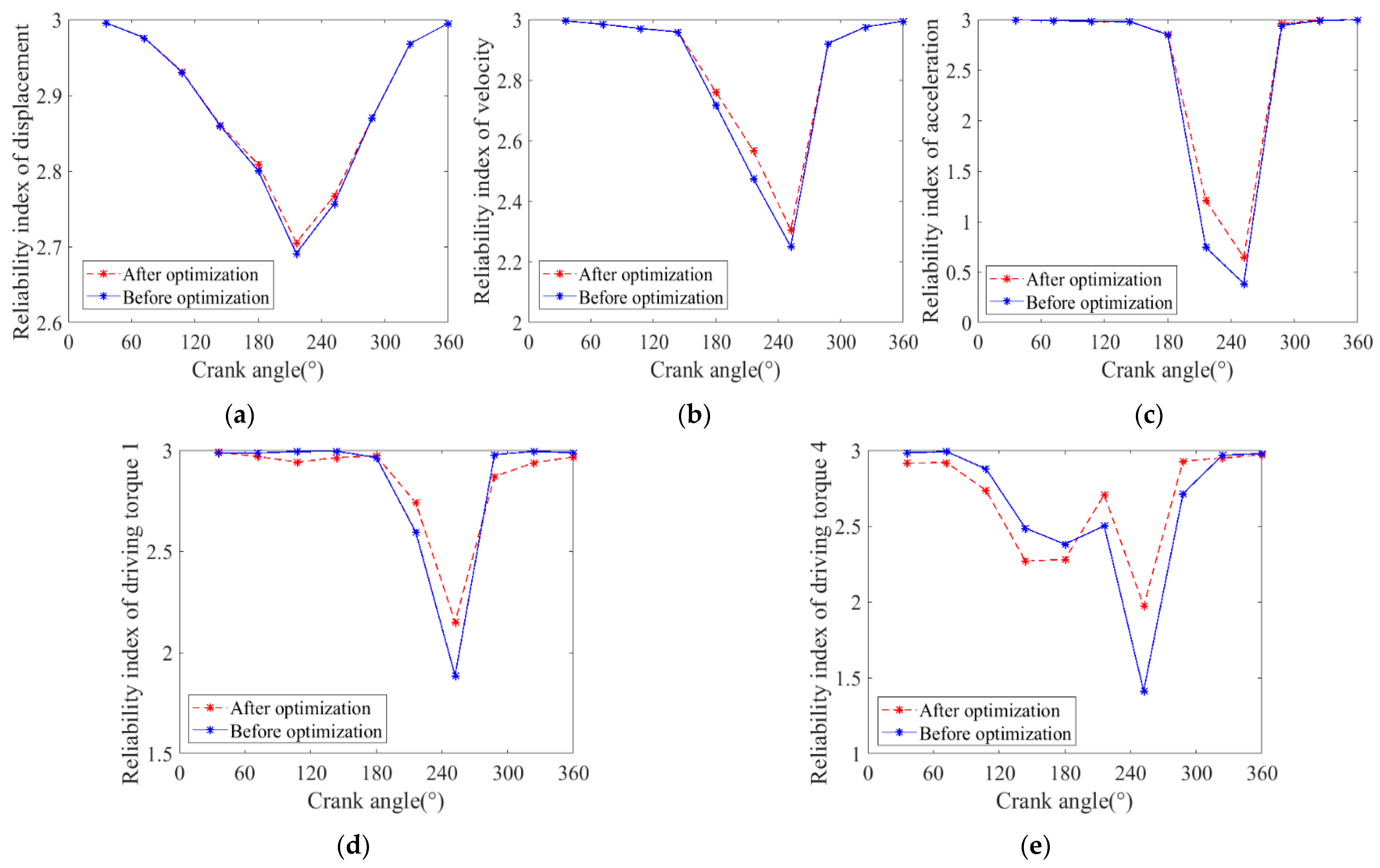
(3) The dynamics accuracy and reliability of the mechanism containing clearances before and after optimization is studied. It is found that the optimization effectively improves the reliability of the mechanism containing clearances.
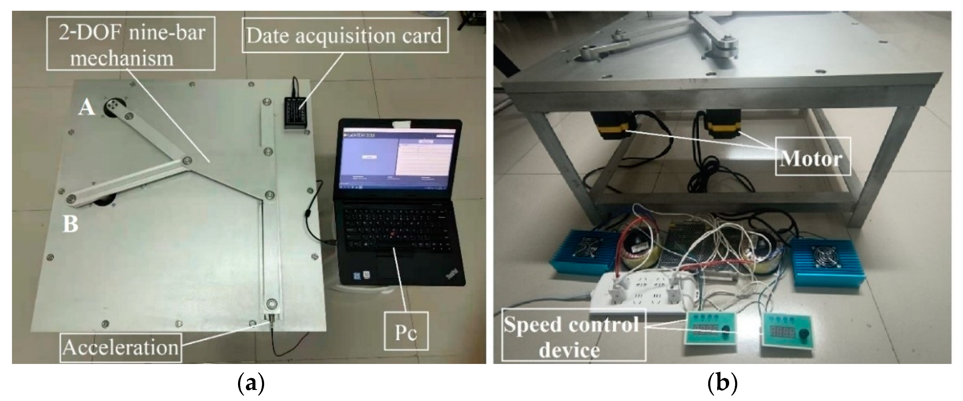
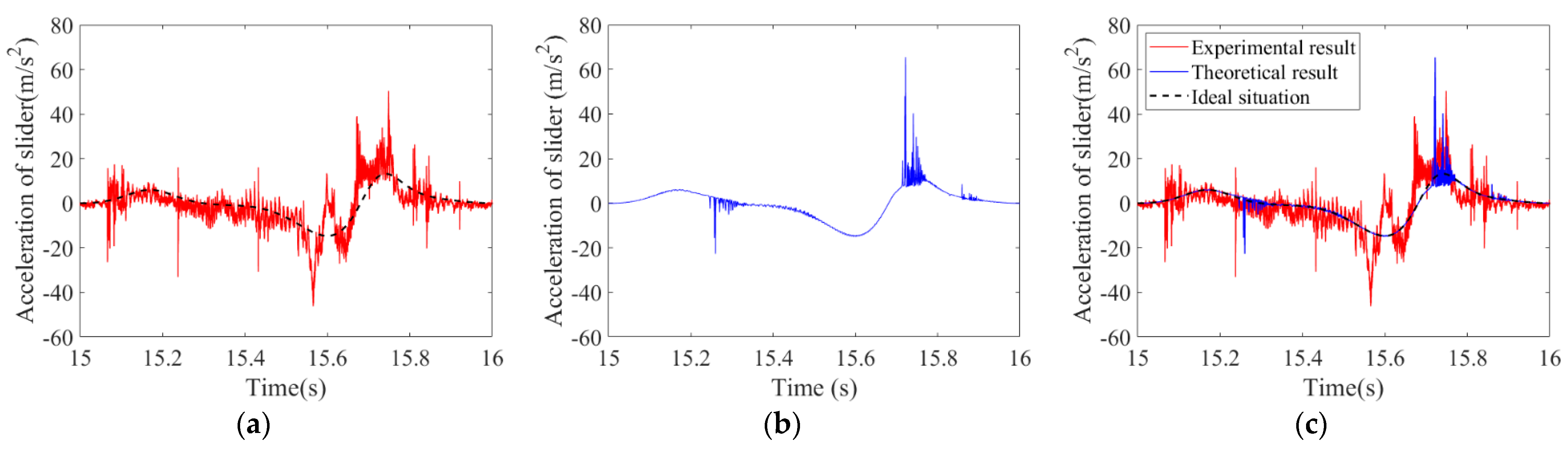
(4) A test platform was built to study the dynamics of the mechanism with clearances. The theoretical result and the experimental result are basically consistent in terms of trends, but there is a certain difference in value. The error rate between the theoretical result and the experimental result is 23.03%, which basically verifies the correctness of the theoretical results.

Author Contributions

Writing original draft, S.J.; Formal analysis, Y.L.; Investigation, J.L.; Methodology, L.X.; Funding acquisition, S.Z. All authors have read and agreed to the published version of the manuscript.

Funding

This research is supported by the National Natural Science Foundation of China (grant no. 61703243).

Institutional Review Board Statement

Not applicable.

Informed Consent Statement

Not applicable.

Data Availability Statement

Not applicable.

Conflicts of Interest

The authors declare that they have no conflict of interest.

References

  1. Zhan, Z.H.; Zhang, X.M.; Zhang, H.D.; Chen, G.C. Unified motion reliability analysis and comparison study of planar parallel manipulators with interval joint clearance variables. Mech. Mach. Theory 2019, 138, 58–75. [Google Scholar] [CrossRef]
  2. Tian, Q.; Flores, P.; Lankarani, H.M. A comprehensive survey of the analytical, numerical and experimental methodologies for dynamics of multibody mechanical systems with clearance or imperfect joints. Mech. Mach. Theory 2018, 122, 1–57. [Google Scholar] [CrossRef]
  3. Li, X.; Zhao, D.; Xie, F.; Wu, S.; Li, X. Experimental investigations of the dynamic responses of a multi-link mechanism with revolute clearance joints. Adv. Mech. Eng. 2021, 13, 1–10. [Google Scholar] [CrossRef]
  4. Li, H.; Xie, J.; Wei, W. Numerical and Dynamic Errors Analysis of Planar Multibody Mechanical Systems with Adjustable Clearance Joints Based on Lagrange Equations and Experiment. J. Comput. Nonlinear Dyn. 2020, 15, 081001. [Google Scholar] [CrossRef]
  5. Marques, F.; Roupa, I.; Silva, M.T.; Flores, P.; Lankarani, H.M. Examination and comparison of different methods to model closed loop kinematic chains using Lagrangian formulation with cut joint, clearance joint constraint and elastic joint approaches. Mech. Mach. Theory 2021, 160, 104294. [Google Scholar] [CrossRef]
  6. Salahshoor, E.; Ebrahimi, S.; Zhang, Y. Frequency analysis of a typical planar flexible multibody system with joint clearances. Mech. Mach. Theory 2018, 126, 429–456. [Google Scholar] [CrossRef]
  7. Wang, X.; Liu, G.; Ma, S.; Tong, R. Study on dynamic responses of planar multibody systems with dry revolute clearance joint: Numerical and experimental approaches-ScienceDirect. J. Sound Vib. 2019, 438, 116–138. [Google Scholar] [CrossRef]
  8. Yu, D.W.; Zhao, Q.Q.; Guo, J.K.; Chen, F.; Hong, J. Accuracy analysis of spatial overconstrained extendible support structures considering geometric errors, joint clearances and link flexibility. Aerosp. Sci. Technol. 2021, 119, 107098. [Google Scholar] [CrossRef]
  9. Acary, V. Projected event-capturing time-stepping schemes for nonsmooth mechanical systems with unilateral contact and Coulomb′s friction. Comput. Method Appl. Mach. Eng. 2013, 256, 224–250. [Google Scholar] [CrossRef]
  10. Wang, C.Z.; Wang, Y.C. Kinematic Accuracy Analysis and Optimization Design for Spatial Steering Mechanisms with Joint Clearances. Chin. Mech. Eng. 2021, 32, 1027–1034. [Google Scholar]
  11. Zhan, Z.H.; Zhang, X.M.; Jian, Z.C.; Zhang, H.D. Error modelling and motion reliability analysis of a planar parallel manipulator with multiple uncertainties. Mech. Mach. Theory 2018, 124, 55–72. [Google Scholar] [CrossRef]
  12. Gao, Y.; Zhang, F.; Li, Y.Y. Robust optimization of planar constrained mechanical system with varying joint clearance size based on sensitivity analysis. Shock Vib. 2020, 2020, 6079249. [Google Scholar] [CrossRef]
  13. Varedi-Koulaei, S.M.; Daniali, H.M.; Farajtabar, M.; Fathi, B.; Shafiee-Ashtiani, M. Reducing the undesirable effects of joints clearance on the behavior of the planar 3-RRR parallel manipulators. Nonlinear Dyn. 2016, 86, 1007–1022. [Google Scholar] [CrossRef]
  14. Etesami, G.; Felezi, M.E.; Nariman-Zadeh, N. Optimal transmission angle and dynamic balancing of slider-crank mechanism with joint clearance using Pareto Bi-objective Genetic Algorithm. J. Braz. Soc. Mech. Sci. 2021, 43, 185. [Google Scholar] [CrossRef]
  15. Sardashti, A.; Daniali, H.M.; Varedi, S.M. Optimal free-defect synthesis of four-bar linkage with joint clearance using PSO algorithm. Meccanica 2013, 48, 1681–1693. [Google Scholar] [CrossRef]
  16. Erkaya, S.; Uzmay, I. Determining link parameters using genetic algorithm in mechanisms with joint clearance. Mech. Mach. Theory 2009, 44, 222–234. [Google Scholar] [CrossRef]
  17. Meng, F.G.; Wu, S.J.; Zhang, Z.L.; Zhang, F.; Zhao, W.Q. Dynamic characteristic analysis optimization of transmission mechanism with clearance based on Taguchi method. J. Cent. South Univ. Sci. Technol. 2016, 47, 3375–3380. [Google Scholar]
  18. Bai, Z.F.; Zhao, J.J.; Chen, J.; Zhao, Y. Design optimization of dual-axis driving mechanism for satellite antenna with two planar revolute clearance joints. Acta Astronaut. 2018, 44, 80–89. [Google Scholar] [CrossRef]
  19. Li, Y.Y.; Chen, G.P.; Sun, D.Y.; Gao, Y.; Wang, K. Dynamic analysis and optimization design of a planar slider-crank mechanism with flexible components and two clearance joints. Mech. Mach. Theory 2016, 99, 37–57. [Google Scholar] [CrossRef]
  20. Varedi, S.M.; Daniali, H.M.; Dardel, M. Dynamic synthesis of a planar slider-crank mechanism with clearances. Nonlinear Dyn. 2015, 79, 1587–1600. [Google Scholar] [CrossRef]
  21. Sun, D.Y.; Shi, Y.; Zhang, B.Q. Robust optimization of constrained mechanical system with joint clearance and random parameters using multi-objective particle swarm optimization. Struct. Multidiscip. Optim. 2018, 58, 2073–2084. [Google Scholar] [CrossRef]
  22. Ding, J.Z.; Wang, C.J. Deployment accuracy analysis of planar satellite antenna with joint clearances. J. Beijing Univ. Aeronaut. Astronaut. 2016, 42, 2625–2631. [Google Scholar]
  23. Li, X.F.; Wu, S.J.; Li, X.Y.; Zhao, D.; Li, Q.Q. A study on the dynamic responses and joints clearance optimization of the planar operating mechanism of high-voltage circuit breaker. Shock Vib. 2019, 2019, 9019718. [Google Scholar] [CrossRef]
  24. Daniali, H.M.; Varedi, S.M.; Dardel, M.; Fathi, A. A novel algorithm for kinematic and dynamic optimal synthesis of planar four-bar mechanisms with joint clearance. J. Mech. Sci. Technol. 2015, 29, 2059–2065. [Google Scholar] [CrossRef]
  25. Ahmedalbashir, M.; Romdhane, L.; Lee, J. Dynamics of a four-bar mechanism with clearance and springs-Modeling and experimental analysis. J. Mech. Sci. Technol. 2017, 31, 1023–1033. [Google Scholar] [CrossRef]
  26. Gao, Y.; Zhang, F.; Li, Y.Y. Reliability optimization design of a planar multi-body system with two clearance joints based on reliability sensitivity analysis. Proc. Inst. Mech. Eng. Part C J. Mech. Eng. Sci. 2018, 233, 1369–1382. [Google Scholar] [CrossRef]
  27. Zhang, J.F.; Du, X.P. Time-dependent reliability analysis for function generation mechanisms with random joint clearances. Mech. Mach. Theory 2015, 92, 184–199. [Google Scholar] [CrossRef]
  28. Wei, P.F.; Song, J.W.; Lu, Z.Z.; Yue, Z.F. Time-dependent reliability sensitivity analysis of motion mechanisms. Reliab. Eng. Syst. Safe. 2016, 149, 107–120. [Google Scholar] [CrossRef]
  29. Zhang, Q.; Pan, N.; Meloni, M.; Lu, D.; Cai, J.G.; Feng, J. Reliability analysis of radially retractable roofs with revolute joint clearances. Reliab. Syst. Saf. Eng. 2021, 208, 107401. [Google Scholar] [CrossRef]
  30. Chen, X.L.; Gao, S. Dynamic accuracy reliability modeling and analysis of planar multi-link mechanism with revolute clearances. Eur. J. Mech. A-Solids 2021, 90, 104317. [Google Scholar] [CrossRef]
  31. Yu, A.D.; Huang, H.Z.; Li, H.; Li, Y.F.; Bai, S. Reliability analysis of rolling bearings considering internal clearance. J. Mech. Sci. Technol. 2020, 34, 3963–3971. [Google Scholar] [CrossRef]
  32. Zhao, K.; Chen, J.J.; Xue, H.; Qiao, X.Z. Reliability analysis of output displacement for slider-crank mechanism including joint with clearance. Chin. J. Appl. Mech. 2016, 33, 596–602. [Google Scholar]
  33. Varedi, S.M.; Daniali, H.M.; Dardel, M.; Fathi, A. Optimal dynamic design of a planar slider-crank mechanism with a joint clearance. Mech. Mach. Theory 2015, 86, 191–200. [Google Scholar] [CrossRef]
  34. Zheng, Y.; Yang, C.; Wan, H.; Luo, Y.; Yu, Y. Dynamics analysis of spatial mechanisms with dry spherical joints with clearance using finite particle method. Int. J. Struct. Stab. Dyn. 2020, 20, 2050035. [Google Scholar] [CrossRef]
  35. Li, Y.; Yang, Y.; Li, M.; Huang, Y. Dynamics analysis and wear prediction of rigid-flexible coupling deployable solar array system with clearance joints considering solid lubrication. Mech. Syst. Signal. Process. 2022, 162, 108059. [Google Scholar] [CrossRef]
  36. Flores, P.; Ambrósio, J.; Claro, J.P. Dynamic analysis for planar multibody mechanical systems with lubricated joints. Multibody Syst. Dyn. 2004, 12, 47–74. [Google Scholar] [CrossRef]
  37. Xiang, W.; Yan, S.; Wu, J.; Niu, W. Dynamic response and sensitivity analysis for mechanical systems with clearance joints and parameter uncertainties using Chebyshev polynomials method. Mech. Syst. Signal. Process. 2020, 138, 106596. [Google Scholar] [CrossRef]
  38. Brüls, O.; Acary, V.; Cardona, A. Simultaneous enforcement of constraints at position and velocity levels in the nonsmooth generalized-scheme. Comput. Methods Appl. Mech. Eng. 2014, 281, 131–161. [Google Scholar] [CrossRef]
  39. Jiang, S.; Chen, X. Test study and nonlinear dynamic analysis of planar multi-link mechanism with compound clearances. Eur. J. Mech. A Solid. 2021, 88, 104260. [Google Scholar] [CrossRef]
  40. Baumgarte, J. Stabilization of constraints and integrals of motion in dynamical systems. Comput. Methods Appl. Mech. Eng. 1972, 1, 1–16. [Google Scholar] [CrossRef]
  41. Erkaya, S.; Dogan, S. A comparative analysis of joint clearance effects on articulated and partly compliant mechanisms. Nonlinear Dynam. 2015, 81, 323–341. [Google Scholar] [CrossRef]
Figure 1. Clearance model of a revolute pair.
Machines 10 00698 g001
Figure 2. The motion mode of revolute clearance. (a) Free flight state; (b) continuous contact state; (c) impact state.
Machines 10 00698 g002
Figure 3. Diagram of a 2-DOF nine–bar mechanism.
Machines 10 00698 g003
Figure 4. Structure diagram of a 2-DOF nine-bar mechanism with revolute clearances.
Machines 10 00698 g004
Figure 5. Comparative analysis of dynamics response before and after optimization. (a) Acceleration. (b) Contact force of joint A. (c) Contact force of joint B. (d) central trajectory of clearance A. (e) central trajectory of clearance B.
Machines 10 00698 g005aMachines 10 00698 g005b
Figure 6. Dynamics response. (a) Displacement of the slider. (b) Velocity of the slider. (c) Acceleration of the slider. (d) Contact force of joint A. (e) Contact force of joint B. (f) Driving torque of crank 1. (g) Driving torque of crank 4. (h) Central trajectory of clearance A. (i) Central trajectory of clearance B.
Machines 10 00698 g006
Figure 7. Nonlinear characteristics of joint A in the X direction. (a) Phase map. (b) Poincaré map.
Machines 10 00698 g007
Figure 8. Nonlinear characteristics of joint A in the Y direction. (a) Phase map. (b) Poincaré map.
Machines 10 00698 g008
Figure 9. Nonlinear characteristics of joint B in the X direction. (a) Phase map. (b) Poincaré map.
Machines 10 00698 g009
Figure 10. Nonlinear characteristics of joint B in the Y direction. (a) Phase map. (b) Poincaré map.
Machines 10 00698 g010
Figure 11. Nonlinear characteristic of the slider’s error. (a) Phase map. (b) Poincaré map.
Machines 10 00698 g011
Figure 12. Reliability index. (a) Displacement. (b) Velocity. (c) Acceleration. (d) Driving torque of crank 1. (e) Driving torque of crank 4.
Machines 10 00698 g012
Figure 13. The 2-DOF nine–bar mechanism test bed. (a) Vertical view. (b) Lateral view.
Machines 10 00698 g013
Figure 14. Structure diagram of the 2-DOF nine–bar mechanism testbed. (a) Normal axonometric drawing. (b) Lateral view. 1—Frame, 2—Support plate, 3—Crank 1, 4—Crank 4, 5—Rod 2, 6—Rod 3, 7—Triangular panel 7, 8—Rod 6, 9—Rod 8, 10—Slider, 11—Guide rail, 12—Motor.
Machines 10 00698 g014
Figure 15. Shaft with clearance (clearance value = 0.1 mm). (a) Shaft A. (b) Shaft B.
Machines 10 00698 g015
Figure 16. Comparison between experimental results and theoretical results. (a) Experimental result. (b) Theoretical result. (c) Comparison diagram.
Machines 10 00698 g016
Table 1. Value ranges of XcU and XcL.
m 2 /kg L s 2 /mm J 2 / ( kg m 2 ) m 3 /kg L s 3 /mm J 3 / ( kg m 2 ) m 9 /kg
XcL 1 2 m 2 0 1 12 m 2 L 2 2 1 2 m 3 0 1 12 m 3 L 3 2 1 2 m 9
XcU 2 m 2 L 2 1 3 m 2 L 2 2 2 m 3 L 3 1 3 m 3 L 3 2 2 m 9
Table 2. Geometric and inertial parameters.
ComponentLength of Rod (mm)Centroid Position Length (mm)Mass (kg)Moment of Inertia
(10−3 kg·m2)
Crank 145230.1480.2382
Rod 23261630.8058.007
Rod 3497248.80.60313.37
Crank 495480.2651.210
Frame 5430
Rod 62301150.58112.12
Triangular panel 7L71 325Ls71 14738.024.334
L72 250Ls72 219
L73 386Ls73 190
Rod 8335167.60.8278.663
Slider 90.801
Table 3. Clearance simulation parameters.
ParameterParameter ValuesParameterParameter Values
Bearing radius R115 (mm)Clearance value0.1 (mm)
Restitution coefficient ce0.9Speed of crank 12π rad/s
Poisson ratio ν1, ν20.3Speed of crank 4−2π rad/s
Elastic modulus E1, E2207 (GPa)Integral tolerance0.000001
Friction coefficient0.01Integral step0.0001 s
Table 4. Geometric and inertial parameters of the test platform.
ComponentLength of Rod (m)Mass (kg)Moment of Inertia (10−3 kg·m2)
Crank 10.080.1420.303
Crank 40.080.1420.303
Rod 20.2500.2841.479
Rod 30.3500.3964.043
Triangular panel 70.247
0.140
0.270
0.8373.076
Rod 60.1800.2063.6863
Rod 80.3000.3412.558
Slider 90.112
Table 5. The comparison between the theoretical and experimental results.
ParameterTheoretical Result (m/s2)Experimental Result (m/s2)Error
Acceleration65.4350.3623.03%
Publisher’s Note: MDPI stays neutral with regard to jurisdictional claims in published maps and institutional affiliations.

