
Introducing Robotized Stator Cable Winding to Rotating Electric Machines

Division for Electricity, Uppsala University, Box 65, 751 03 Uppsala, Sweden
Machines 2022, 10(8), 695; https://doi.org/10.3390/machines10080695
Submission received: 24 June 2022
/
Revised: 3 August 2022
/
Accepted: 13 August 2022
/
Published: 15 August 2022
(This article belongs to the Section Advanced Manufacturing)
Abstract
:Following environmental concerns and the rapid digitalization of our society, we are currently experiencing an extensive electrification and industrial revolution. High numbers of electric machines thus need to be assembled for varying applications, including vehicle propulsion and renewable energy conversion. Cable winding is an alternative stator winding technology for electric machines that has been utilized for such applications, so far in smaller series or in prototype machines. The presented work introduces the first concept for automated stator cable winding of rotating electric machines. This concept could enable higher production volumes of cable wound machines and a unique flexibility in handling different machines, in line with Industry 4.0. Robotized stator cable winding is evaluated here for five very different rotating machine designs, through simulations and analytical extrapolation of previous experimental winding results. Potential cycle time and assembly cost savings are indicated compared to manual and lower volume conventional automation, while it is not possible to compete in the present form with existing very high-volume conventional winding automation for smaller machines. Future experimental work is pointed out on handling larger winding cables and special machine designs, and on increased robustness and optimization.
1. Introduction
A thorough transition of our society is required to increase our global environmental and ecological sustainability and fulfil the related global sustainability goals defined by the United Nations [1,2,3]. This includes increased efforts towards more renewables, higher energy efficiency and cleaner transports, all pointing towards an increased use of different electric machines. Thus, a thorough adaptation of the manufacturing industry is required as well, with the present electrification of vehicle propulsion systems and increase in distributed renewable electric generation systems as clear examples [4,5]. At the same time, we are rapidly entering a new manufacturing era. Digitalization, connectivity, flexibility, and further increased automation are all important aspects of what is referred to as Industry 4.0 [6,7,8]. Managed wisely, this industrial revolution can provide new opportunities for sustainability [9]. Hence, we get into a situation where we need to produce electric machines in larger and more varying series using modern production methods [10].
Conventional electric machines are typically wound with strands of induction wire (smaller machines) or rectangular inductor bars (larger machines). Beyond assembling the winding into the stator, additional pre-forming, insulation, fixation and connection are typically required. Stator winding automation for conventional small and medium sized electric machines is well established [11,12,13,14] and continuously developed with a focus on efficiency [15,16,17,18,19], flexibility [20,21,22] and intelligent manufacturing [23,24,25], while it is little implemented for larger machines [26,27,28]. Examples of recent work focus on additive manufacturing [29,30], hairpin windings [31,32] and sprayed phase insulation [33]. The rapidly increasing use of electric vehicles is clearly pushing the development [34].
An alternative electric machine design, with a cable wound stator, was developed and introduced by ABB around the year 2000 [35,36]. Cable winding has so far been implemented for different machines in smaller volumes or prototypes, including generators for hydropower [37], wind energy [38,39,40], wave power [41] and hydrokinetic energy [42], and motors for offshore installations [43] and all electric vehicle propulsion systems [44,45]. The main potential advantages compared to conventional machine designs are higher efficiency and durability, together with fewer assembly steps since the windings are formed and fixated with pre-insulated cables that are fed through the stator. However, the time consuming, labor intense and tiresome manual stator winding process has been a bottleneck for producing cable wound electric machines in a larger series.
In previous work at Uppsala University (UU), the first concept for robotized stator cable winding has been introduced, developed and validated [27,46,47]. The concept has been demonstrated as fully automated in full scale with linear stators for wave energy converter generators; see Figure 1. This includes different linear stator designs, sizes and winding patterns within the same equipment and different cable dimensions with only tools changing. Hence, high flexibility has already been achieved and the fully developed concept would enable large scale manufacturing of linear cable wound machines.
Robotized stator cable winding uses articulated industrial robots, working in pair(s) to push and pull the winding cable through slot holes in the stator. The robots are equipped with special cable feeder tools [48], making it possible to fetch, guide, grab, direct, feed and drop the winding cable with high precision and reliability. A tube-shaped cable guiding system makes it possible to work close to the stator sides, and a push handle is used to hold and push down the end windings. During a complete winding process [27], the position and orientation of the stator section to be wound is first measured in a special Work Object Coordinate System (WOCS) positional calibration procedure using proximity sensors mounted on the cable feeder tools [49]. Winding cable is delivered from an automated cable drum feeder equipment where the cable end is automatically formed to a tip—to facilitate winding—and cut to the required lengths [50]. Winding is performed with the cable being directed into and pushed through a slot hole in the stator section by one robot and received on the other side by the other robot in the pair. The first robot can now drop the cable and hold down the end winding while being pulled. Hereby, the cable is pulled through one slot hole at the time and the remaining cable is fed out on the floor. After the end winding is pulled, the second robot moves along the cable and feeds the cable backwards through the tool—again out on the floor—to find the cable end. The process is then repeated as the second robot is positioned towards the next slot hole to wind, until the complete cable is wound. Finally, the end windings are pushed down and the next winding cable is wound, until the stator winding is completed. If two winding robot pairs are used, the winding is performed from the middle of each cable and in opposite directions towards the ends of the stator section by the two robot pairs. The only manual intervention required is to initiate the winding process using an extensive Graphical User Interface (GUI)—from where the desired winding pattern is defined, the process is supervised, and equipment service is performed—implemented on a touch screen, replace empty winding cable drums and connect the winding cables after the automated process.
The possibility to transfer robot cable winding also to rotating electric machines—in other words to implement the robot winding concept on round stators—has been briefly mentioned in earlier work but not investigated in detail. It would nevertheless provide a unique product flexibility to the winding automation concept, clearly in line with the new manufacturing era. While the task is similar to winding a linear machine, a few aspects deriving from the round stator design need particular consideration. This includes robot reach with large diameter stators, adaptive tool orientation, robot positioning generation and offset in polar coordinates, and flexibility to handle different round stator designs.
This paper investigates the general and conceptual potential for robotized stator cable winding of rotating electric machines through analysing a representative selection of reference machine designs. Specific challenges with round stators as well as critical electric machine design aspects are addressed in detail. Robot winding is also compared both to manual winding and to conventional winding automation regarding potential assembly cycle times and costs. The ambition is to take a first step towards robot cable winding for rotating machines and define the path for future research within the field. In Section 2, five different round reference stator designs are presented together with the method used for validation and evaluation. Section 3 presents the results from this evaluation, the results are discussed in Section 4 and conclusions are given in Section 5.
2. Materials and Methods
Evaluating the potential of robot cable winding in detail is best done using realistic applications. Since cable winding can be used for very different rotating electric machines, the presented work was based on two reference machine sizes. The potential for robotized stator cable winding was evaluated through robot winding simulations and extrapolation of previous experimental results for three different robot winding development scenarios. It was also compared to manual winding and conventional winding automation where applicable in terms of cycle times and assembly costs.
Adapting the robot cable winding process to rotating machines will require some scaling and minor modifications to the process equipment. However, the same principal equipment design as for linear stators could still be used. Since this equipment has been experimentally validated in earlier work, the most critical initial development steps for adjusting to rotating machines are to identify necessary adjustments to the winding process and to evaluate robot positioning against round stators.
2.1. Stator Reference Design 1
An interesting application for cable wound electric machines is generators for renewable energy conversion. These machines are typically medium to large sized, depending on the application. The largest machines, such as generators used for hydropower, are produced in very limited numbers and use very large winding cables. It is therefore relevant and feasible to investigate robot winding of medium–large-sized machines intended for higher numbers applications, such as generators for wind and hydrokinetic energy. A 225 kW cable wound prototype wind energy generator developed at UU [39] was chosen as the first sub design of medium large machines to investigate. Since commercial wind energy turbines are rated several MWs today, a 1.5 MW cable wound wind energy generator from the Swedish company Vertical Wind AB was also evaluated. Due to the large size, the stator of this generator was divided into three 120° sections in manual assembly. To cover a wider range of stator designs and machine applications, the stator from a cable wound prototype hydrokinetic energy generator developed at UU [42] was evaluated as well. The three sub designs of medium-large rotating machine stators are hereafter referred to as Stator reference designs 1a–c (S1a–c); see Figure 2. Table 1 presents geometric stator characteristics that are relevant for the robot winding evaluation of S1a–c.
2.2. Stator Reference Design 2
Considering the rapid transition to all electric vehicles and that electric machines in corresponding sizes are used in many industrial applications, it was decided to evaluate robotized stator cable winding also for such smaller machines. A 6.2 kW cable wound vehicle propulsion motor prototype developed at UU [45] was chosen as the first sub design of smaller machines to investigate. The chosen stator design use double concentrated windings in open slots, which is a new challenge for robotized cable winding. A stator design with distributed winding and separate slot holes is however possible and has also been developed at UU [44], so a variant of this design is therefore evaluated as well. Smaller electric machines are not designed with cable winding and hence not investigated here. The two sub designs of smaller rotating machine stators are hereafter referred to as Stator reference designs 2a–b (S2a–b); see Figure 3. Table 2 presents geometric stator characteristics that are relevant for the robot winding evaluation of S2a–b.
2.3. Robot Winding Simulations
Stator cable winding puts high demands on positioning and orientation freedom for equipment to be used during an automated process. A six-joint articulated industrial robot manipulator—such as the ones used in the robot winding—provide full 6-Degrees-of-Freeedom motion freedom with relatively large reach and high positioning accuracy. Nevertheless, the motion freedom can still be partly limited within the manipulator work envelope, due to joint configuration constraints close to mechanical singularities, joint limits and the maximum reach. The model and placement of the winding robots in relation to other equipment and the stator are therefore crucial and positioning against the stator must be evaluated with all required orientations. When positioning between different slot holes and adjusting to different winding patterns on a linear stator, simple positioning offset in Cartesian coordinates with consistent orientation is sufficient. With a rotating machine design on the other hand, higher motion freedom is however required as the orientation now needs to be adjusted relative to the stator curvature. This can be facilitated by shifting from Cartesian to polar coordinates when defining robot motions, but also require a larger robot reach and more consideration of joint configurations. As in the previous work, industrial robot manipulators and controllers from ABB Robotics were used.
To evaluate manipulator model choice, placement, reach and positioning for the winding of rotating machines, all stator reference designs were conceptually modelled and imported as 3D-geometries to the industrial robot simulation and offline programming software ABB Robotstudio. The robot cable feeder tools and cable preparation equipment from [27] were reused, while new industrial robot systems were selected, and the robot cell layout was reworked to investigate if sufficient motion freedom could be achieved.
A Matlab script was used to facilitate the generation of robot targets relative to all stator reference designs. By parameterizing the script programming relative to a round stator geometry and using polar coordinates, new stator designs could easily be implemented. Robot targets were then automatically generated by translating the stator slot hole positions to Cartesian coordinates, as is used in the robot controller. Key robot targets were then imported to ABB Robotstudio for the robot winding simulation and detailed evaluation.
2.4. Winding Scenarios and Cycle Time Analysis
Estimations on the process cycle time for robotized stator cable winding were achieved by combining detailed cycle time results from previous winding experiments [27] with the geometric and winding characteristics of S1–2. The cycle times were divided into feeding time, other time and WOCS time for consistency with the previous work. Feeding time included all process time where the cable feed velocity was the limiting factor and WOCS time included stator positional calibration and robot cell initiation/resetting. The remaining other time mainly consisted of robot positioning and tooling operation. Three different development levels for the robot winding concept, hereafter referred to as Winding development scenarios 0–2 (W0–2), were used for the evaluation:
- W0—a validated winding scenario;
- W1—a developed winding scenario;
- W2—a further developed winding scenario.
The W0 scenario corresponds to the validated PR scenario from [27], but with a separate cable preparation robot. Experimentally validated cable feed velocity—0.7 m/s—and other process time estimations were used here. The W1 scenario was similar to the D2 scenario from [27]. Here, the cable feed velocity was increased to 0.9 m/s and a 40% reduction of the experimental other process time was assumed. In the W2 scenario—more comparable to the D3 scenario from [27]—the cable feed velocity and the other process experimental time reduction were further increased to 1.4 m/s and 50%. The need to hold down the end windings while being pulled was also neglected in this scenario. For all investigated scenarios, the winding robots were assumed to wind cable into the stator continuously, the drum feed velocity was assumed to be equal to the robot cable feed velocity and pushing down the end windings after being pulled was neglected.
The robot’s other process time was estimated from the previous winding experiments to 54 s per slot hole, with 20 s of this for holding down the end windings while being pulled. To estimate the cable feeding process time, an average cable feed distance per slot hole was calculated. This included first feeding the cable through a stator slot hole and then finding the cable end by feeding the pulled cable back again through the cable feeder tool. An extra cable length of 2 m for both connecting ends was required for the robot handling. The WOCS process time was estimated to 5 min per stator section for all stator designs.
2.5. Economical Analysis
The output and cycle time results for the derived robotized stator winding solutions for S1–2 in this work were compared to the manual winding process data presented in Table 1 and Table 2 and to conventional winding automation where applicable. Two different economical production scenarios, hereafter referred to as Production scenarios 1–2 (P1–2), were used for the assembly cost estimations:
- P1—a low salary production scenario;
- P2—a high salary production scenario.
Since cable wound machines have not been produced in high volumes and larger machines are mainly assembled manually, it is not straightforward to compare robotized cable winding to other winding automations. However, commercial automated winding solutions for high series production of conventional electric vehicle motors are common, and has been investigated and exemplified in [4]. These solutions include both coil winding and impregnation assembly lines, and can be compared to the derived robot winding solutions for S2. A production situation with 1,000,000 stators per year, 6000 h production time per year, five years depreciation time and 3.5 EUR/h operator wage is used in this reference study. Those parameters are used here in the P1 scenario. The faster lines have complete winding cycle times of 2–3 min per stator with 1–5 operators, and the investment cost is about 4,000,000 EUR. An alternative simpler and less automated solution for coil winding only with cycle time 15 min, ten operators and investment cost about 90,000 EUR is also presented. Floor space, power consumption, discount rate and rest value were not specified or used in the referred work.
The P2 scenario was consistent with the economical evaluation of robotized and manual stator cable winding of the linear UU wave energy stators in precious work [27]. The parameters used here were: five years depreciation time, 4% discount rate, 25% investment rest value, 20 EUR/h manual personnel cost, 30 EUR/h robot operator personnel cost, 0.1 EUR/m2/h floor space cost and 0.1 EUR/kWh electricity cost.
The collected production data and results were used in an economic analysis with the parameters from P1–2. Assembly costs relative to robotized winding were estimated for manual winding of S1–2 with P1-2 and for conventional winding automation of S2 with P1. The production pace was adjusted to 1000 stators per year for S1 and to 25,000 stators/year for S2 when compared to manual winding. Investment and maintenance costs for the developed robot cells were consistent with previous work [27] for S2, while extra height was taken for more expensive robots and equipment with S1. New estimations on the electrical power consumption were made for the robot cells, based on data from the robot and equipment manufacturers and with guidance from research in the field [51].
3. Results
The main results from the present work are the robot winding process validation followed by suggested robot cell layouts, analytical winding cycle time estimations and assembly cost comparisons to manual and conventional stator winding.
3.1. The Winding Process
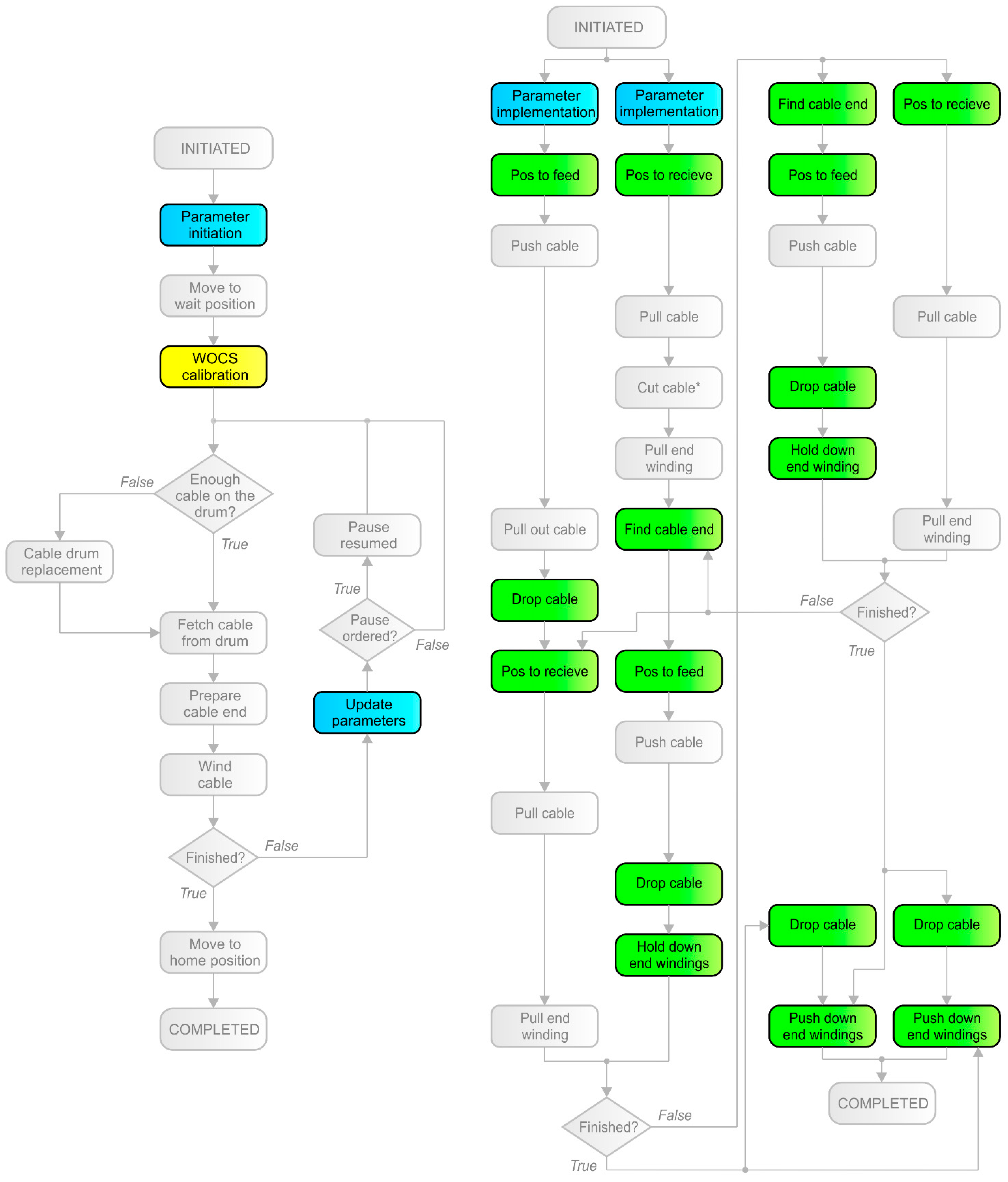
By analyzing the previous robotized stator cable winding process developed for linear stators [27], the Programmable Logic Controller (PLC) and robot controller sub-procedures being most critical to adjust for the winding of rotating machines were identified; see Figure 4. Those identified procedures can be sorted into three groups: winding parameter generation, robot positioning and WOCS calibration.
Winding parameter generation includes the parameterization of different winding patterns and stator designs in the PLC process controller and the definition of specific robot targets for the automated winding process in the robot controllers. In the present work, the winding parameter generation was demonstrated through automatic generation of key robot targets in the developed Matlab-script and validated through direct implementation in ABB Robotstudio for the simulations presented below.
Robot positioning includes four different types of robot controller sub-procedures: against a slot hole to be wound, to drop the winding cable, to find the cable end and to hold or push down end windings. All such positioning must be defined based on well thought out assembly motions. In particular, cable twisting must be avoided as the cable is wound between different slot holes and the gravity force acting on the cable must be considered. This requires different measures depending on the stator design and winding pattern, as explained in detail below. After several iterations with different robot models and placements, optimized robot cell layouts were derived for S1–2 respectively. Simulations in ABB Robotstudio validated that sufficient reach could be achieved for the winding procedure relative all stators. For S1, the robots were placed on pedestals to provide sufficient reach without physically interfering with the winding process. It was, however, not always straightforward to find suitable robot models and placements, especially, for the common full flexibility robot cell layout for all S1–2 utilized, the manipulator reaches close to its maximum. Holding and pushing down the end windings was more complex compared to linear stators and could not be evaluated in detail without physical experiments, due to the cable deformability. Simulation validations were performed for numerous robot targets along the full stators, and a general process illustration is shown in Figure 5.
The WOCS positional calibration method with robot-held proximity sensors would need to be adjusted to the round stator design without straight edges to measure against. Shifting to a machine vision system for the positional calibration measurements would, however, likely be a faster, more cost-effective and more robust approach.
3.2. Stator Reference Design 1
This section presents the results for robot winding of the larger rotating cable wound machines, exemplified with the wind energy and hydrokinetic energy generators presented in Section 2.1.
3.2.1. Robot Cell Design
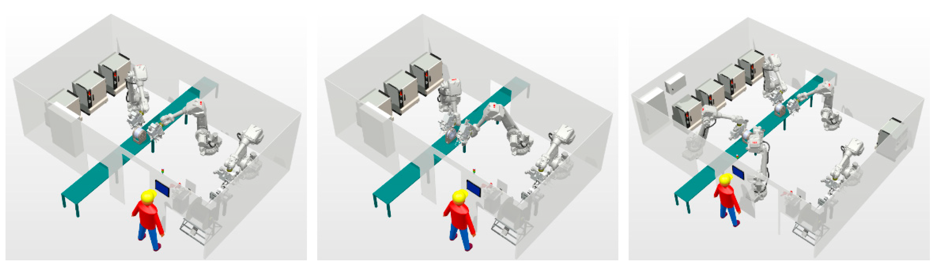
A common robot cell design with four winding robots and one cable preparation robot was developed and simulated for all three larger rotating machines S1a–c; see Figure 6. To achieve sufficient reach relative the different stators, ABB IRB 6650S industrial robots with 3.90 m reach and 90 kg payload capacity were used and placed on 1.2 m high pedestals for the winding. An ABB IRB 4600 industrial robot with 2.05 m reach and 60 kg payload capacity was used for the cable preparation. The complete cell floor dimensions were 8.5 × 10.5 m. A 3.5 m wide light curtain supervised openings in the cell fence to allow stator transportation through the cell and enable a smooth workflow. A smaller fence opening allowed cable drum replacement from the outside. The complete robot cell investment cost, including installation and commissioning, was estimated to be about 750,000 EUR. It was estimated that one operator could both supervise the robot cell and perform the following manual winding cables connection assembly step. The average electric power consumption of the robot cell was roughly estimated to be 15 kW and the maintenance cost to be 50,000 EUR/year.
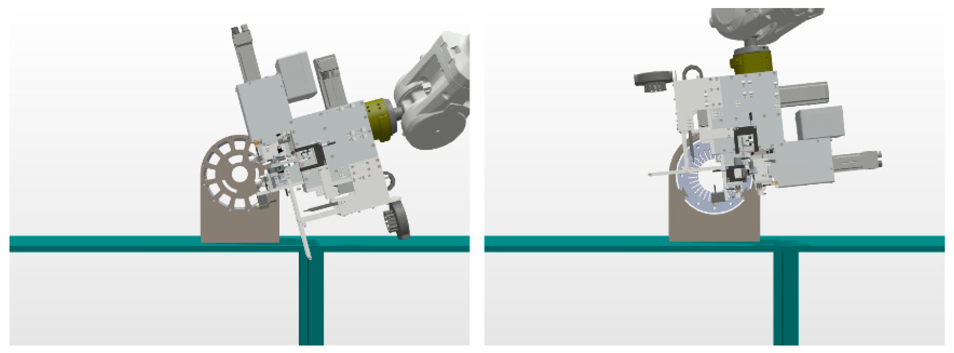
Robot reach and placement in the cell were critical for achieving the desired positioning against all slots on the stators, due to the large variation in stator dimensions. Smaller robots and cell designs were possible for winding only S1a and S1c. It was necessary to synchronize the work of the winding robot pairs—the second pair starting 90° after the first pair with full round stators—to avoid robot collision and cable tangling. The winding was performed in both directions, starting and ending at the bottom slots for S1a and S1c. For S1b, the winding started at the bottom slot and ended at the ends of the stator section. Robot positioning relative to the stator slots was performed with the cable feeder tools directed radially from the inside or outside of the stator—with respect to the robot axis configuration—to avoid cable twisting as the end windings were pulled, hence tool rotation to vertical was required when dropping the cable; see Figure 7.
3.2.2. Cycle Time Estimations
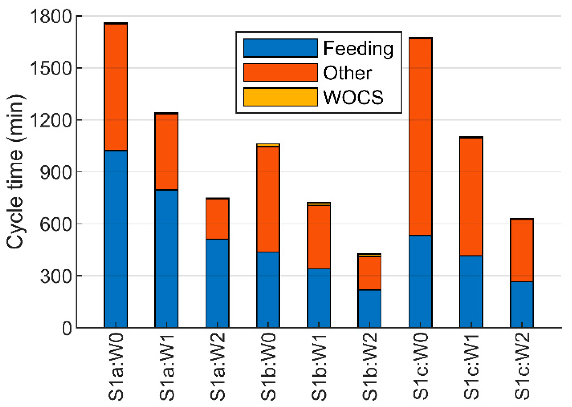
The winding cycle time was estimated to be about 13–30 h for the smaller prototype wind energy generator stator, about 7–18 h for the larger wind energy generator stator—that is, all three sections required for a full stator—and about 11–28 h for the hydrokinetic energy generator stator; see Figure 8.
3.2.3. Assembly Cost Estimations
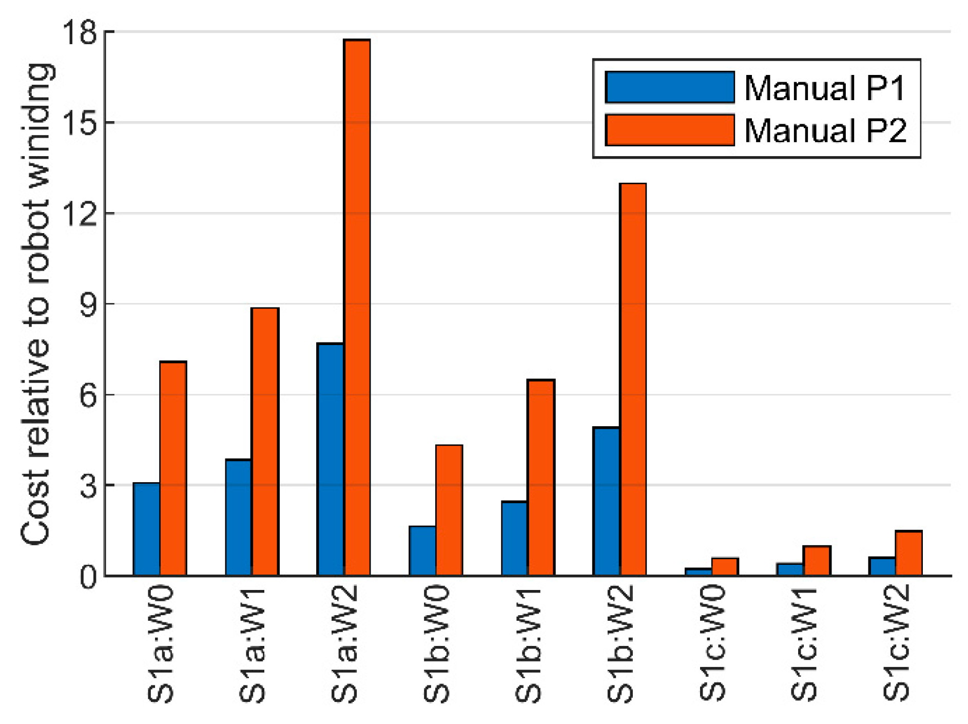
The rough economical comparison between manual and robotized stator cable winding for the larger rotating wind energy machines indicated that robotized winding would be considerably less costly using the low salary P1 scenario, down about one eighth in cost. When compared to manual winding of the hydrokinetic energy machine on the other hand, robotized winding was indicated to be about 60% more costly for the developed winding scenarios. About 90% of the total winding assembly cost derived from the investment, and 1–5 robot cells were required to fulfil the desired production pace.
With the high salary P2 scenario, it was indicated that robotized winding would be even less costly compared to manual winding for the larger wind energy machines, down to about one-eighteenth in cost. For the hydrokinetic machine, the cost for robotized winding was indicated to be similar to manual winding in W1 and about 30% less costly in W2.
A summarized assembly cost comparison of manual stator cable winding relative to the different robot stator cable winding development scenarios and for the two production scenarios is presented in Figure 9.
3.3. Stator Reference Design 2
This section presents the results for robot winding of the smaller rotating cable wound machines, exemplified with the all-electric vehicle propulsion motors presented in Section 2.2.
3.3.1. Robot Cell Design
A common robot cell design with two winding robots and one cable preparation robot was developed and simulated for the two smaller rotating machines S2a–b; see Figure 10. ABB IRB 4600 industrial robots with 2.05 m reach and 60 kg payload capacity were used both as winding robots and for the cable preparation. The complete cell floor dimensions were 3.5 × 6.0 m. A conveyor enabled a smooth workflow with stator transportation through the cell. A smaller fence opening allowed cable drum replacement from the outside. The complete robot cell investment cost, including installation and commissioning, was estimated to about 300,000 EUR. To increase the productivity, the robot cell could be equipped with two winding robot pairs, winding one stator each simultaneously. This extended cell would be about 5.0 × 6.5 m, and the investment cost was estimated to about 450,000 EUR. It was estimated that one operator could both supervise the robot cell and perform the following manual winding cables connection assembly step. The average electric power consumption of the robot cell was roughly estimated to be 10 kW and the maintenance cost to be 35,000 EUR/year.
Robot reach and placement in the cell were critical for achieving the desired positioning against all slots on the stators, due to the full round stators being wound by a single robot pair. The winding started and ended at the bottom slots. Robot positioning relative the stator slots was performed with the cable feeder tools directed radially from the inside or outside of S2a and radially perpendicular from above or below S2b—depending on the winding pattern and with respect to the robot axis configuration—to avoid cable twisting as the end windings were pulled; see Figure 11. Tool rotation to vertical was required when dropping the cable.
3.3.2. Cycle Time Estimations
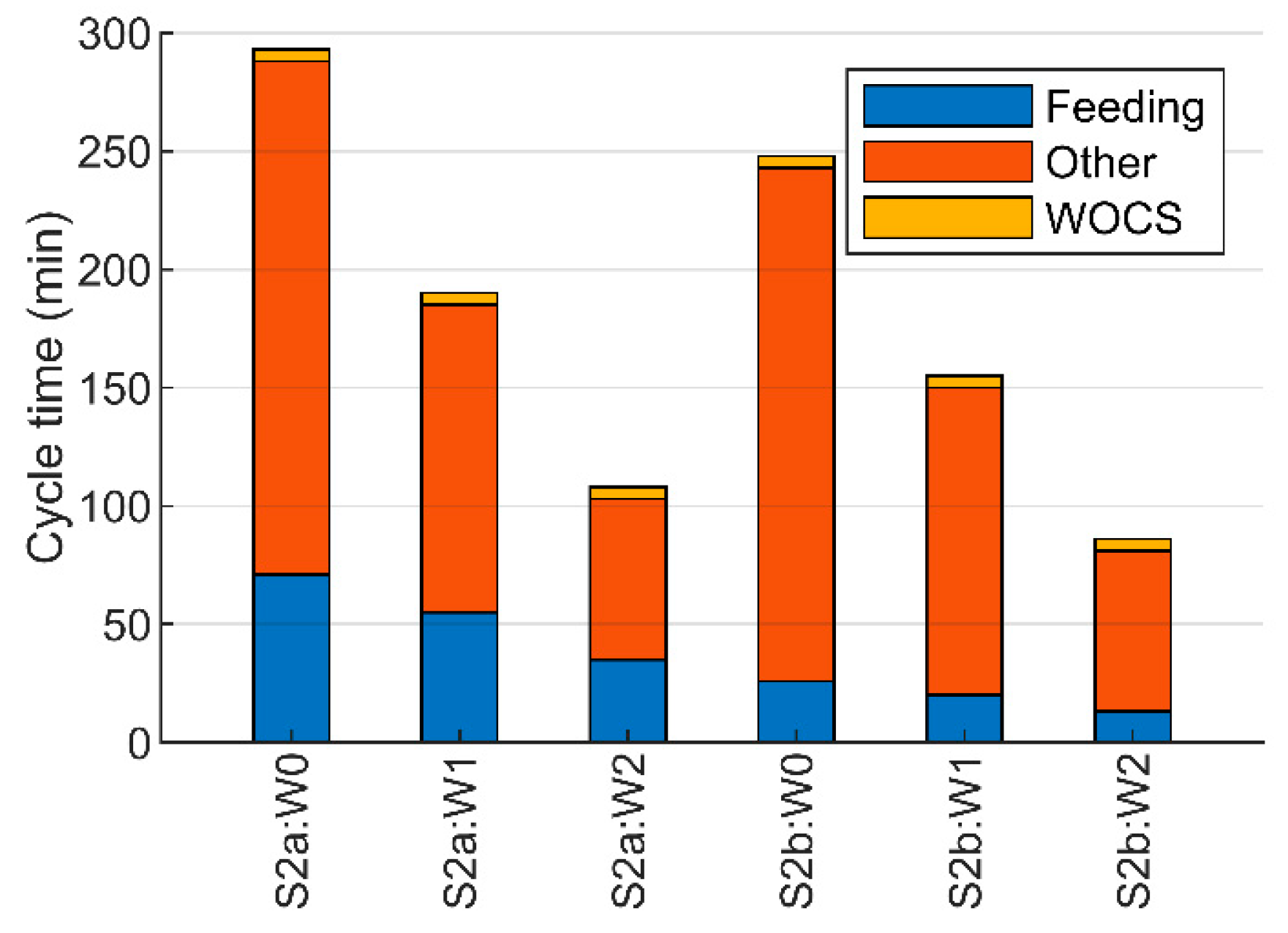
The winding cycle time was estimated to about 2–5 h for the vehicle motor stator with concentrated windings and about 1–4 h for the vehicle motor stator with distributed windings; see Figure 12.
3.3.3. Assembly Cost Estimations
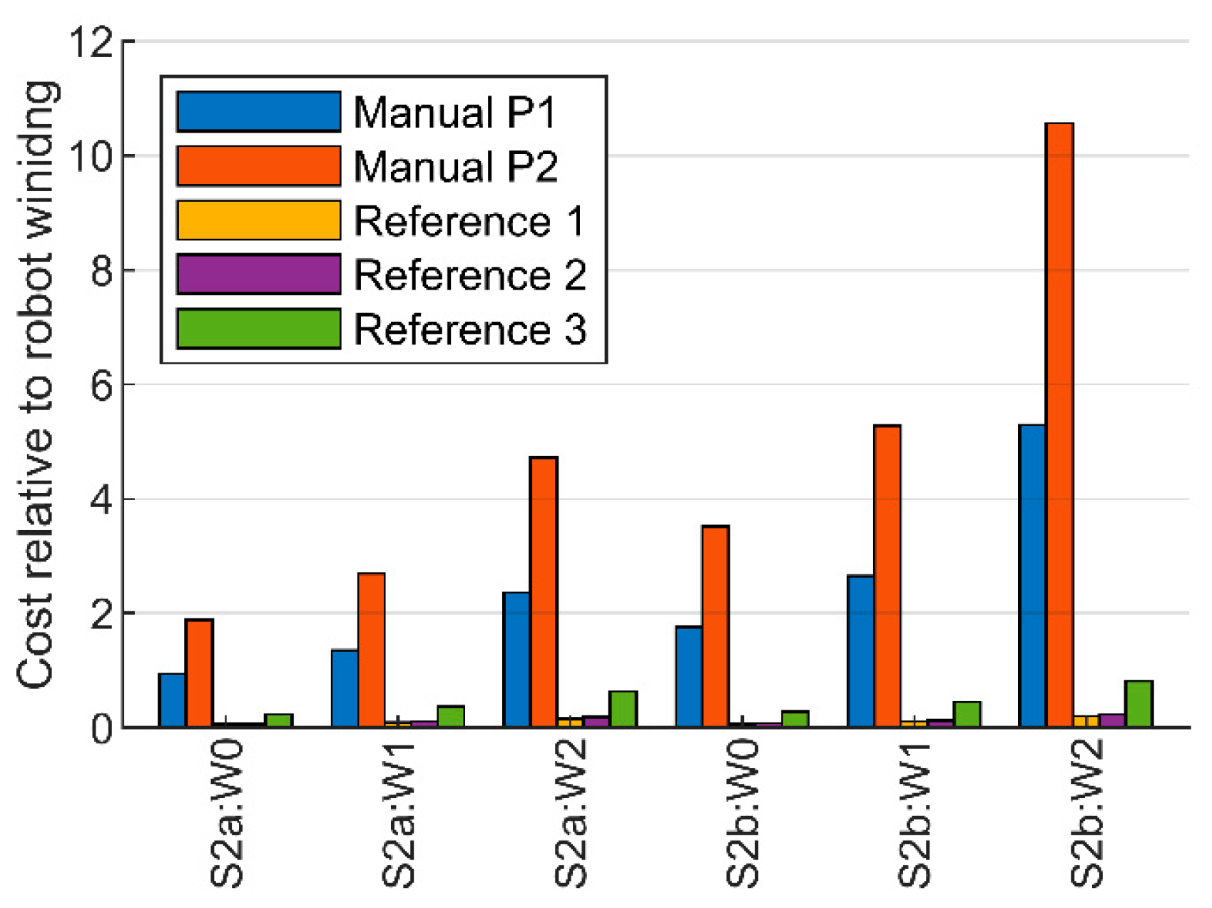
The rough economical comparison between manual and robotized cable stator winding for the smaller rotating machines indicated that robotized winding would be considerably less costly using the low salary P1 scenario, down to about one fifth in cost. About 80% of the total winding assembly cost derived from the investment and 3–10 robot cells were required to fulfil the desired production pace of 25,000 stators/year. Compared to the very high throughput automated winding assembly lines for conventional electric machines from [4], it was indicated that robotized cable winding would be much more costly in higher production volumes, at a minimum of about four times in cost. Compared to the simpler lower throughput conventional assembly solution, it was however indicated that robotized cable winding could be only 20% more costly. Fulfilling the high production pace of 1,000,000 stators/year used in this reference would require about 120–150 robot cells.
With the high salary P2 scenario, it was indicated that robotized winding would be even less costly compared to manual winding, down to about one eleventh in cost.
A summarized assembly cost comparison of manual stator cable winding and conventional automated stator winding relative to the different robot stator cable winding development scenarios and for the two production scenarios where applicable is presented in Figure 13.
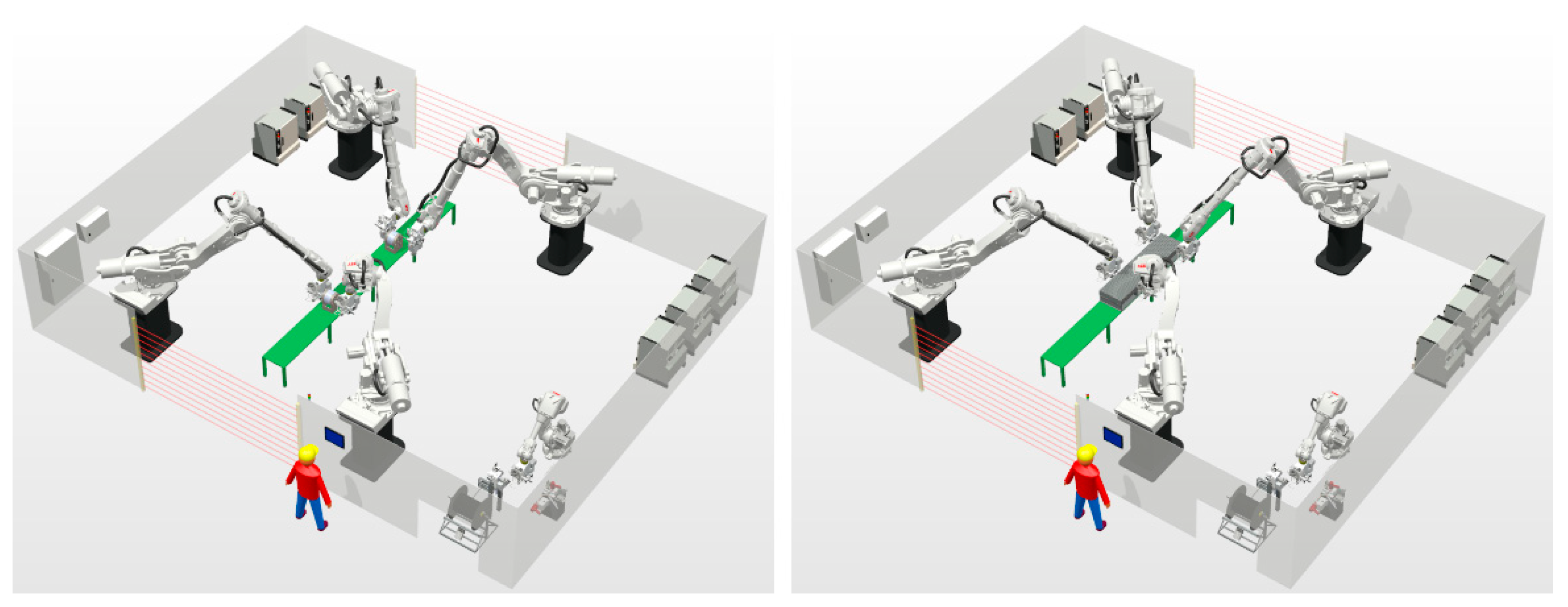
3.4. Full Flexibility Robot Cell
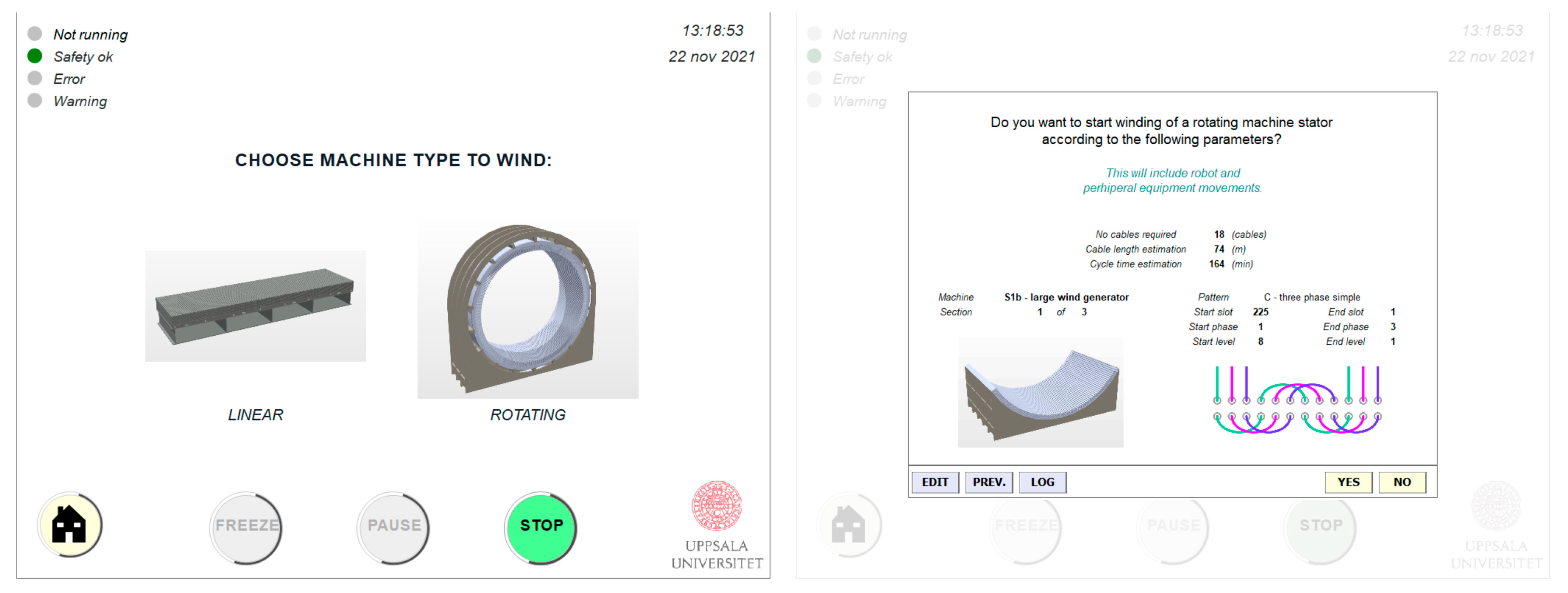
To demonstrate the product flexibility of robotized stator cable winding, robot winding positioning was simulated also for the S2 machines and a linear UU wave energy generator stator—investigated in earlier work [27]—in the larger robot cell developed for S1 in this work. With the smaller S2 machines, the winding robot pairs wound one stator each simultaneously, while the two robot pairs wound the linear stator together; see Figure 14. The winding cycle times were consistent with the results presented in Section 3.2.2 and Section 3.3.2, and in the earlier work. Furthermore, the GUI implemented on an operator process control touch screen in the earlier work could easily be extended to cover all types of machines; see Figure 15.
4. Discussion
The presented study investigates the potential for robotized stator cable winding of rotating electric machines. In the following subsections, this potential is discussed in detail. Limitations and challenges to full scale implementation as well as stator design parameters with particular importance for robot winding are also highlighted.
4.1. Conceptual Potential
Robotized stator cable winding has been evaluated for rotating electric machines through robot simulations, where reach and positioning with automated robot target generation have been validated for winding of different stator designs. This is the first proposed automated stator cable winding solution for rotating machines, a task that has earlier only been performed manually. The proposed robot cell has been demonstrated to provide unique potential in product flexibility compared to conventional stator winding automation. The range of stator designs that could be wound in the same equipment—with only change of tools for handling different cable dimensions—would range from linear to round machines in very different dimensions, designs and with different winding patterns. An automatic tool change system would enable fast and smooth readjustment between different stator designs and ensure the high flexibility in practice with varying series.
While the presented robot cell designs were developed for high product flexibility, customized robot cells for specific stator designs are possible as well. The robot cell dimensions and cable preparation equipment could likely be further optimized with respect to floor space and investment cost, in particular for uniform stator series. Combining this novel winding flexibility with fully connected and synchronized equipment as well as integrated data analysis through a sophisticated GUI in a fully automated and adaptive process, the developed robot cells clearly align with the forefront in the present industrial revolution.
4.2. Cycle Time Potential
The presented winding cycle time results are clearly sensitive for the assumptions made on further winding process developments. For larger and longer machines (S1a–b), cable feeding is the most time-consuming, while, for thinner (S1c) and smaller machines (S2a–b), robot positioning and tooling take up the most time. There are additional measures that could be investigated to further reduce the winding cycle times—for example pulling the cable through several slots at the same time as suggested in [46]—and additional time optimizations could be possible in particular for the smaller S2 machines. Robotized winding was estimated to be much faster than manual winding. It must however also be kept in mind that the manual times are for prototype machines, so there is likely room for improvements there as well. In particular, the presented manual winding times for S1a are very long and could likely be significantly reduced in up-scaled production. However, manual winding is still a repetitive, labor intense and exhausting task with an added risk for very costly mistakes such as errors in the winding pattern or damage to the winding cable.
4.3. Assembly Cost Potential
Keeping in mind that the estimated robot cell investment costs are very rough, it has been indicated through the presented work that robotized stator cable winding can be considerably less costly compared to manual winding even with production volumes of a few hundred S1 stators or a few thousand S2 stators per year, but more so for higher volumes. For the S1c hydrokinetic energy conversion generator stator on the other hand, manual winding was indicated to be significantly less expensive compared to robot winding in the low salary P1 production scenario. This is due to a short manual winding time estimation and time-consuming robot positioning with many but short slot holes.
A particularly interesting result was that the assembly cost for robot winding could be in the same order of magnitude as simpler commercial winding assembly lines for conventional vehicle propulsion motors. Robot cable winding would on the other hand not be able to compete in the present form with commercial special automated assembly lines for conventional vehicle propulsion motors with very high throughput. Very high production volumes would moreover also require an unrealistic high number of robot cells. The high salary P2 production scenario could not be used when comparing robot winding of the S2 machines to conventional winding automation, due to lack of data in the referred work [4]. This would, however, benefit robot winding over simpler existing conventional winding automation, so that robot winding could then possibly be significantly less expensive than conventional winding automation.
4.4. Limitations and Challenges
It should be noted that a complete evaluation and comparison to conventional winding must also include the costs for stator material and other assembly steps, as well as motor efficiency, robustness and performance for the different stator design concepts. Additional development work is also required to implement the robotized stator cable winding concept in actual production, as outlined below.
The performed robot simulations did not include complete winding processes, due to very long cycle times and to limited possibility to simulate equipment, sensor feedback and cable handling. The latter instead need to be investigated through physical experiments, as has previously been done for linear machines. No extra time was added to compensate for productions stops or positioning synchronization between robot winding pairs in the process cycle time estimations. It is clear that round stators require a higher freedom in tool orientation compared to linear stators, and hence put higher demands on the robot reach. Some adjustments to the cable guiding system and energy chain on the cable feeder tools are therefore required.
The cable feeder tools also need to be adjusted for handling new cable dimensions. In particular, the large cables used in S1b will be a new challenge due to their size, weight and stiffness. This could also influence the choice of winding robot model, if higher process forces are required. Cable feed velocities of up to 1.5 m/s have been verified in previous work [48], but continuous winding experiments were limited to 0.7 m/s. Therefore, further work is needed to ensure robustness and prevent damaging the cable insulation with higher velocities. It is likely that smaller cable dimensions are more feasible for higher feed velocities. Handling and feeding the large cables used in S1b could be considerably more time consuming than for the other stator reference designs, and this must be considered when interpreting the cycle time and assembly cost results.
An important challenge that remains from previous winding experiments, and could be even more challenging with round stators, is how to handle long cable parts during the winding. The previous approach to feed it out on the floor must be further experimentally investigated and validated in terms of robustness. A cable parking, as suggested in [46], might be needed for larger machines. Another remaining challenge is to ensure consistently pulled end windings. It has previously been shown that the end winding quality much depends on the winding pattern and on the type of winding cable, so new experimental evaluations for the round stators are required.
4.5. General Stator Design Aspects
If the stator and winding design can be adjusted to facilitate robot winding, it could benefit both the productivity and the robustness of the assembly process. There are some important lessons to consider in particular. From robot winding experience with linear stators, it has been concluded that pulling end windings between very close slots increases the risk of cable kinking. Manual winding experience on the other hand has stressed that handling and compact fixation of longer end windings in smaller stators for two-pole motors is challenging and that more rotor poles—and thereby shorter end windings—are favorable. Evaluation of the robot winding cycle times has pointed out that the number of electric phases and cables per phase—in practice the cable lengths—has a large effect on the cycle time results, with increased cycle times for fewer but longer cables. Manual connection of the winding cables after the robot winding is, however, also time consuming. Longer cables—as well as multiple cables that are wound together in fractional winding patterns—are also more challenging to handle in robot winding.
The assembly procedure in the investigated robot winding concept is to feed the winding cable through slot holes in the stator. Hence, the cable is directed into and guided through the stator, and can be received at a precise position on the other side of the stator. Two of the investigated reference stator designs do, however, not have separate slot holes. S1b has an open slot design where the winding cables are put down from above during manual winding. When all cables are wound, the windings are fixed in the slots using wedges. Robot winding with this procedure would require a redesigned robot cell and need to be experimentally validated in terms of cable handling. With shorter cable parts to handle, fewer winding robots and less cable preparation, there is, however, an interesting potential to achieve shorter cycle times in a lower investment cost robot cell with this winding method. S2a on the other hand have closed but large slots that are shared by 20 cables in a concentrated winding pattern design. Hence the cable must be fed unguided through the slots and the cable end must be detected and adaptively received with precision on the other side of the stator. It could be challenging to achieve precise winding loops in those slots. Adjustments to the cable guiding system and implementation of 3D machine vision sensors on the cable feeder tools are likely required for this stator design.
Finally, the stator support structure should be considered. It must both support the stator during winding and allow transportation through the robot cell, without hindering robot positioning over the stator sides during the winding. In the investigated robot winding concept, winding is performed horizontally through laying stator sections. Manual winding of S1a and S1c were, however, performed vertically, with the stators standing up. Thus, either laying placement supports or adjusting to vertical robot winding is required for those stators.
5. Conclusions
Robot positioning and reach for robotized stator cable winding have been evaluated for different rotating electric machines. A potentially unique flexibility to wind stators in very different dimensions, designs and winding patterns within the same robot cell has been demonstrated through simulations. The highly connected, adaptive and interactive robot cell design is clearly in line with the present industrial revolution. Fully developed robotized stator cable winding for rotating electric machines could enable a broader use of cable wound machines in applications such as electric vehicle propulsion and renewable energy conversion.
Robot stator cable winding is estimated to be faster and less costly for most machines in higher series compared to manual cable winding. It is also likely to provide a better work environment and winding quality. It is indicated that the robot winding concept could compete with simpler commercial assembly lines for conventional vehicle stators, but not in its present form with special winding automation for conventional vehicle stators in very high series.
A thorough evaluation with conventional winding automations should however also consider the material costs, other assembly steps and the electric machine performance. Further experimental work is also needed mainly on cable handling and robustness. Large and long winding cables, open stator slot designs and complicated end windings could be particular challenges.
Funding
This research received no external funding.
Data Availability Statement
The data presented in this study are available in the article.
Acknowledgments
The author expresses gratitude to Juan de Santiago, Sandra Eriksson and Karin Thomas for providing data on the cable wound electric machines for vehicle propulsion motors, wind energy generators and a hydrokinetic energy generator from Uppsala University and to Nils Wahlberg for providing data on the cable wound wind energy generator from Vertical Wind AB.
Conflicts of Interest
The author declares no conflict of interest.
References
- UN. Transforming Our World: The 2030 Agenda for Sustainable Development; United Nations: New York, NY, USA, 2015. [Google Scholar]
- IPCC. Climate Change 2021: The Physical Basis; Cambridge University Press: Cambridge, UK; New York, NY, USA, 2021. [Google Scholar]
- IPCC. Summary for policymakers. In IPCC Special Report on Renewable Energy Sources and Climate Change Mitigation; Cambridge University Press: Cambridge, UK; New York, NY, USA, 2011. [Google Scholar]
- Du-Bar, C.; Mann, A.; Wallmark, O.; Werke, M. Comparison of performance and manufacturing aspects of an insert winding and a hairpin winding for automotive machine application. In Proceedings of the International Electric Drives Production Conference, Schwinfurt, Germany, 4–5 December 2018. [Google Scholar]
- Pepermans, G.; Driesen, J.; Haeseldonckx, D.; Belmans, R.; D’haeseleer, W. Distributed generation: Definition, benefits and issues. Energy Policy 2005, 33, 787–798. [Google Scholar] [CrossRef]
- Lasi, H.; Fettke, P.; Kemper, H.G.; Feld, T.; Offman, M. Industry 4.0. Bus. Inf. Syst. Eng. 2014, 6, 239–242. [Google Scholar] [CrossRef]
- El Maraghy, H. Smart changeable manufacturing systems. Procedia Manuf. 2019, 28, 3–9. [Google Scholar] [CrossRef]
- Krüger, J.; Wang, L.; Verl, A.; Bauernhansl, T.; Carpanzano, E.; Makris, S.; Fleischer, J.; Reinhart, G.; Franke, J.; Pellegrinelli, S. Innovative control of assembly systems and lines. CIRP Ann. 2017, 66, 707–730. [Google Scholar] [CrossRef]
- Ghobakhloo, M. Industry 4.0, digitalization, and opportunities for sustainability. J. Clean. Prod. 2020, 252, 119869. [Google Scholar]
- Mayr, A.; Weigelt, M.; von Lindenfels, J.; Seefried, J.; Ziegler, M.; Mahr, A.; Urban, N.; Kühl, A.; Hüttel, F.; Franke, J. Electric motor production 4.0—Application potentials of Industry 4.0 technologies in the manufacturing of electric motors. In Proceedings of the International Electric Drives Production Conference, Schweinfurt, Germany, 4–5 December 2018. [Google Scholar]
- Kirkhoff, J. Automation in electric motor stator processing. Coil Wind. Int. 1980, 4, 4–9. [Google Scholar]
- Vanden Berg, T.A. Manufacturing flat coil configurations for stepper motors. In Proceedings of the Electrical Electronics Insulation Conference and Electrical Manufacturing & Coil Winding Conference, Rosemont, IL, USA, 18–21 September 1995. [Google Scholar]
- Libert, F.; Soulard, J. Manufacturing methods of stator cores with concentrated windings. In Proceedings of the IET International Conference on Power Electronics, Machines and Drives, Dublin, Ireland, 4–6 April 2006. [Google Scholar]
- Moreale, P. Electric motor and generator manufacturing myths. In Proceedings of the Electrical Insulation Conference and Electrical Manufacturing Expo, Nashville, TN, USA, 22–24 October 2007. [Google Scholar]
- Akita, H.; Nakahara, Y.; Miyake, N.; Oikawa, T. New core structure and manufacturing method for high efficiency of permanent magnet motors. In Proceedings of the Industry Application Conference, Salt Lake City, UT, USA, 12–16 October 2003. [Google Scholar]
- Stenzel, P.; Dollinger, P.; Richnow, J.; Franke, J. Innovative needle winding method using curved wire guide in order to significantly increase the copper fill factor. In Proceedings of the International Conference on Electrical Machines and Systems, Hangzhou, China, 22–25 October 2014. [Google Scholar]
- Sell-Le Blanc, F.; Hofmann, J.; Simmler, R.; Fleischer, J. Coil winding process modelling with deformation based wire tension analysis. CIRP Ann. 2016, 65, 65–68. [Google Scholar] [CrossRef]
- Glaessel, T.; Seefried, J.; Franke, J. Challenges in the manufacturing of hairpin windings and application opportunities of infrared lasers for the contacting process. In Proceedings of the International Electric Drives Production Conference, Würzburg, Germany, 5–6 December 2017. [Google Scholar]
- Hofmann, J.; Lepold, A.; Fleischer, J. Analytical modeling of the winding trajectory of the multi-wire needle winding process. Procedia CIRP 2020, 88, 497–502. [Google Scholar] [CrossRef]
- Kuehl, A.; Furlan, S.; Gutmann, J.; Meyer, M.; Franke, J. Technologies and processes for the flexible robotic assembly of electric motor stators. In Proceedings of the IEEE International Electric Machines and Drives Conference, Miami, FL, USA, 21–24 May 2017. [Google Scholar]
- Gerngroß, M.; Herrmann, P.; Westermaier, C.; Endisch, C. Highly flexible needle winding kinematics for traction stators based on a standard industrial robot. In Proceedings of the International Electric Drives Production Conference, Würzburg, Germany, 5–6 December 2017. [Google Scholar]
- Matenga, A.; Murena, E.; Kanyemba, G.; Mhlanga, S. A novel approach for developing a flexible automation system for rewinding an induction motor stator using robotic arm. Procedia Manuf. 2019, 33, 296–303. [Google Scholar] [CrossRef]
- Rodriguez, A.; Vrancx, P.; Nowé, A.; Hostens, E. Model-free learning of wire winding control. In Proceedings of the Asian Control Conference, Istanbul, Turkey, 23–26 June 2013. [Google Scholar]
- Sugimoto, Y. Machine Learning Apparatus and Coil Producing Apparatus. U.S. Patent No. 1,001,967,4B2, 10 July 2018. [Google Scholar]
- Mayr, A.; Kißkalt, D.; Lomakin, A.; Graichen, K.; Franke, J. Towards an intelligent linear winding process through sensor integration and machine learning techniques. Procedia CIRP 2021, 96, 80–85. [Google Scholar] [CrossRef]
- Itagaki, T.; Hiwasa, H.; Haga, K. Design and manufacturing technology of Fuji Electric’s large-capacity air-cooler turbine generator. Chall. Power Eng. Environ. 2007, 1–2, 395–399. [Google Scholar]
- Hultman, E.; Leijon, M. Robotized stator cable winding. Robot. Comput. Integr. Manuf. 2018, 53, 197–214. [Google Scholar] [CrossRef]
- Mahr, A.; Mayr, A.; Jung, T.; Franke, J. Robot-assisted concept for assembling form coils in laminated stator cores of larger electric motors. Procedia Manuf. 2019, 38, 866–875. [Google Scholar] [CrossRef]
- Selema, A.; Ibrahim, M.N.; Sergeant, P. Additively-manufactured ultra-light shaped-profile windings for HF electrical machines and weight-sensitive applications. IEEE Trans. Transp. Electrif. 2022. [CrossRef]
- Selema, A.; Ibrahim, M.N.; Sergeant, P. Metal additive manufacturing for electrical machines: Technology review and latest advancements. Energies 2022, 15, 1076. [Google Scholar] [CrossRef]
- Fleischer, J.; Hausmann, L.; Wirth, F. Production-oriented design of electric traction drives with hairpin winding. Procedia CIRP 2021, 100, 169–174. [Google Scholar] [CrossRef]
- Kuehl, A.; Franke, J. Robot-based forming of hairpin winding. In Proceedings of the IEEE International Electric Machines & Drives Conference, Virtual Event, 17–20 May 2021. [Google Scholar]
- Mahr, A.; Kneidl, M.; Regler, J.; Franke, J. Process design and evaluation for the automation of interphase insulation for distributed windings. Procedia Manuf. 2021, 55, 226–231. [Google Scholar] [CrossRef]
- Selema, A.; Ibrahim, M.N.; Sergeant, P. Electrical machines winding technology: Latest advancements for transportation Electrification. Machines 2022, 10, 563. [Google Scholar] [CrossRef]
- Leijon, M.; Dahnlgren, M.; Walfridsson, L.; Li, M.; Jaksts, A. A recent development in the electrical insulation systems of generators and transformers. IEEE Electron. Insul. Mag. 2001, 17, 10–15. [Google Scholar] [CrossRef]
- Bolund, B.; Leijon, M.; Lundin, U. Poynting theorem applied to cable wound generators. IEEE Trans. Dielectr. Electr. Insul. 2008, 15, 600–605. [Google Scholar] [CrossRef]
- Alfredsson, S.; Harnnäs, B.; Bergström, H. Assembly of generators with rated voltage higher than 100 kV. In Proceedings of the International Conference on Power System Technology, Perth, Australia, 4–7 December 2000. [Google Scholar]
- Dahlgren, M.; Frank, H.; Leijon, M.; Owman, F.; Walfridsson, L. Windformer—Wind power goes large-scale. ABB Rev. 2000, 3, 31–37. [Google Scholar]
- Eriksson, S.; Bernhoff, H.; Leijon, M. A 225 kW direct driven PM generator adopted to a vertical axis wind turbine. Adv. Power Electron. 2011, 2011, 239061. [Google Scholar] [CrossRef]
- Apelfröjd, S.; Eriksson, S.; Bernhoff, H. A review of research on large scale modern vertical axis wind turbines at Uppsala University. Energies 2016, 9, 570. [Google Scholar] [CrossRef]
- Hultman, E.; Ekergård, B.; Kamf, T.; Salar, D.; Leijon, M. Preparing the Uppsala University wave energy converter generator for large-scale production. In Proceedings of the International Conference on Ocean Engineering, Halifax, NS, Canada, 4–6 November 2014. [Google Scholar]
- Grabbe, M.; Yuen, K.; Apelfröjd, S.; Leijon, M. Efficiency of a directly driven generator for hydrokinetic energy conversion. Adv. Mech. Eng. 2013, 5, 978140. [Google Scholar] [CrossRef]
- Lamell, J.O.; Trumbo, T.; Nestli, T. Offshore platform powered with new electrical motor drive system. In Proceedings of the Petroleum and Chemical Industry Conference, Denver, CO, USA, 12–14 September 2005. [Google Scholar]
- Leijon, M.; Ekergård, B.; Apelfröjd, S.; de Santiago, J.; Bernhoff, H.; Waters, R.; Eriksson, S. On a two pole motor for electric propulsion system. Int. J. Eng. Sci. Innov. Technol. 2013, 2, 99–111. [Google Scholar]
- De Santiago, J.; Ali, A.; Oliveira, J.G.; Strömstedt, E. Analysis of a spoke type motor without connecting magnetic bridges. IEEE Trans. Transp. 2022. submitted. [Google Scholar]
- Hultman, E.; Leijon, M. Utilizing cable winding and industrial robots to facilitate the manufacturing of electric machines. Robot. Comput. Integr. Manuf. 2013, 29, 246–256. [Google Scholar] [CrossRef]
- Hultman, E.; Leijon, M. A cable feeder tool for robotized cable winding. Robot. Comput. Integr. Manuf. 2014, 30, 577–588. [Google Scholar] [CrossRef]
- Hultman, E.; Leijon, M. An updated cable feeder tool design for robotized stator cable winding. Mechatronics 2018, 49, 197–210. [Google Scholar] [CrossRef]
- Hultman, E.; Leijon, M. Six Degrees of Freedom (6-DOF) work object positional calibration using a robot-held proximity sensor. Machines 2013, 1, 63–80. [Google Scholar] [CrossRef]
- Hultman, E.; Leijon, M. Automated cable preparation for robotized stator cable winding. Machines 2017, 5, 14. [Google Scholar] [CrossRef]
- Meike, D.; Ribickis, L. Energy efficient use of robotics in the automobile industry. In Proceedings of the International Conference on Advanced Robotics, Tallinn, Estonia, 20–23 June 2011. [Google Scholar]
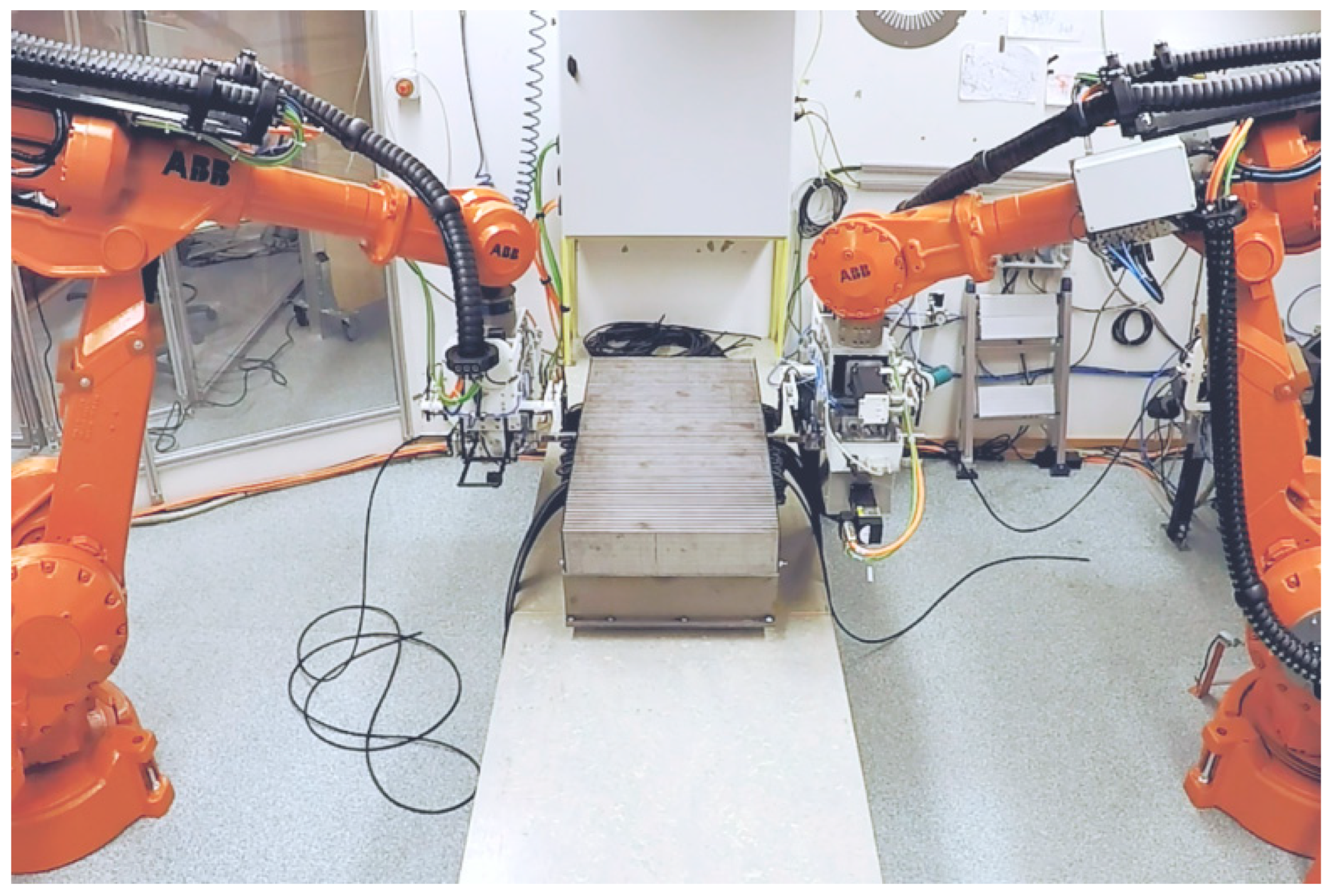
Figure 1.
Robotized stator cable winding validated in full scale on a linear wave energy converter generator stator at UU in 2017, photo from [27].
Figure 1.
Robotized stator cable winding validated in full scale on a linear wave energy converter generator stator at UU in 2017, photo from [27].

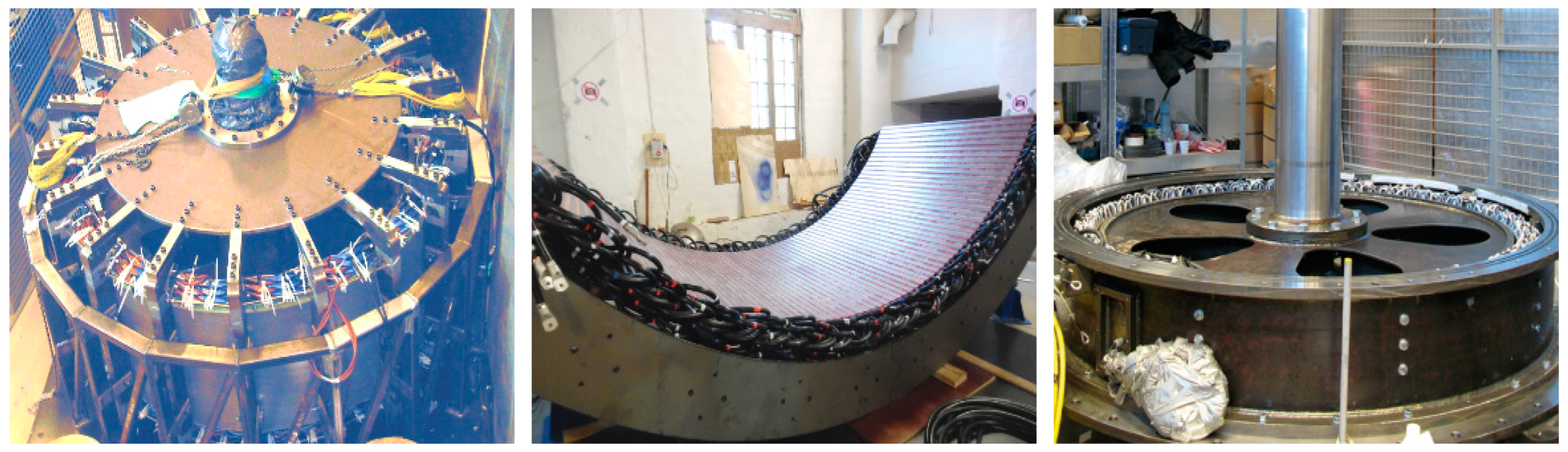
Figure 2.
The renewable energy conversion generators used as examples of a medium–large rotating cable wound electric machine in this paper: The wind energy generator S1a (left), photo from [39], a stator section from wind energy generator S1b (middle), photo from Vertical Wind AB, and the hydrokinetic energy generator S1c (right), photo from [42].

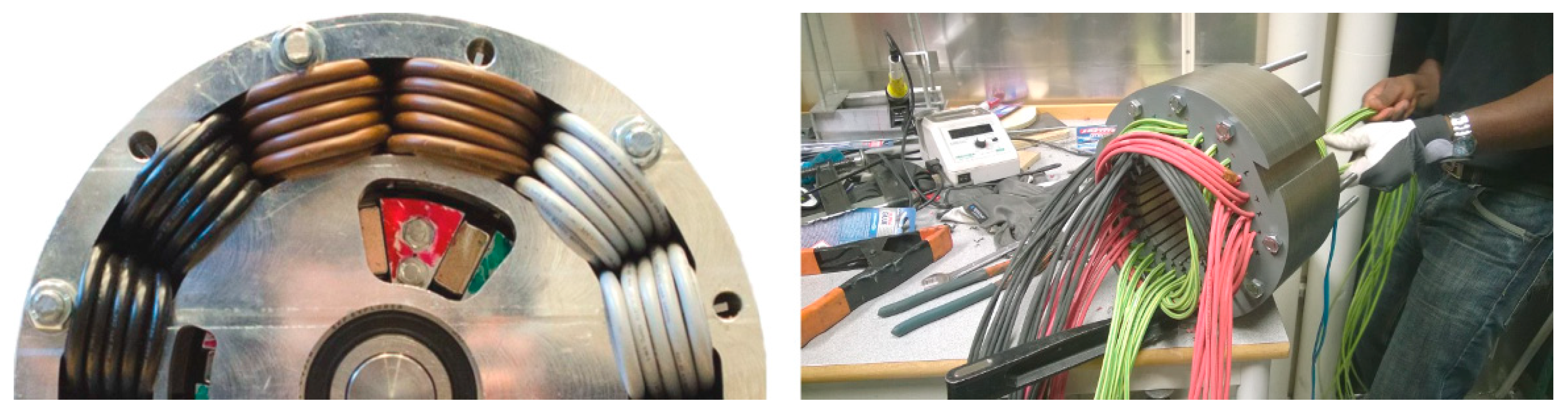
Figure 3.
The electric vehicle propulsion motors developed at UU and used as examples of smaller rotating cable wound electric machine in this paper: The vehicle propulsion motor S2a (left), photo from [45], and the vehicle propulsion motor S2b (right).
Figure 3.
The electric vehicle propulsion motors developed at UU and used as examples of smaller rotating cable wound electric machine in this paper: The vehicle propulsion motor S2a (left), photo from [45], and the vehicle propulsion motor S2b (right).

Figure 4.
Detailed illustrations of the PLC (left) and robot controller (right) processes for robotized stator cable winding, with the sub-procedures most critical to adjust to adapt to rotating machines highlighted. Original figures are from [27].
Figure 4.
Detailed illustrations of the PLC (left) and robot controller (right) processes for robotized stator cable winding, with the sub-procedures most critical to adjust to adapt to rotating machines highlighted. Original figures are from [27].

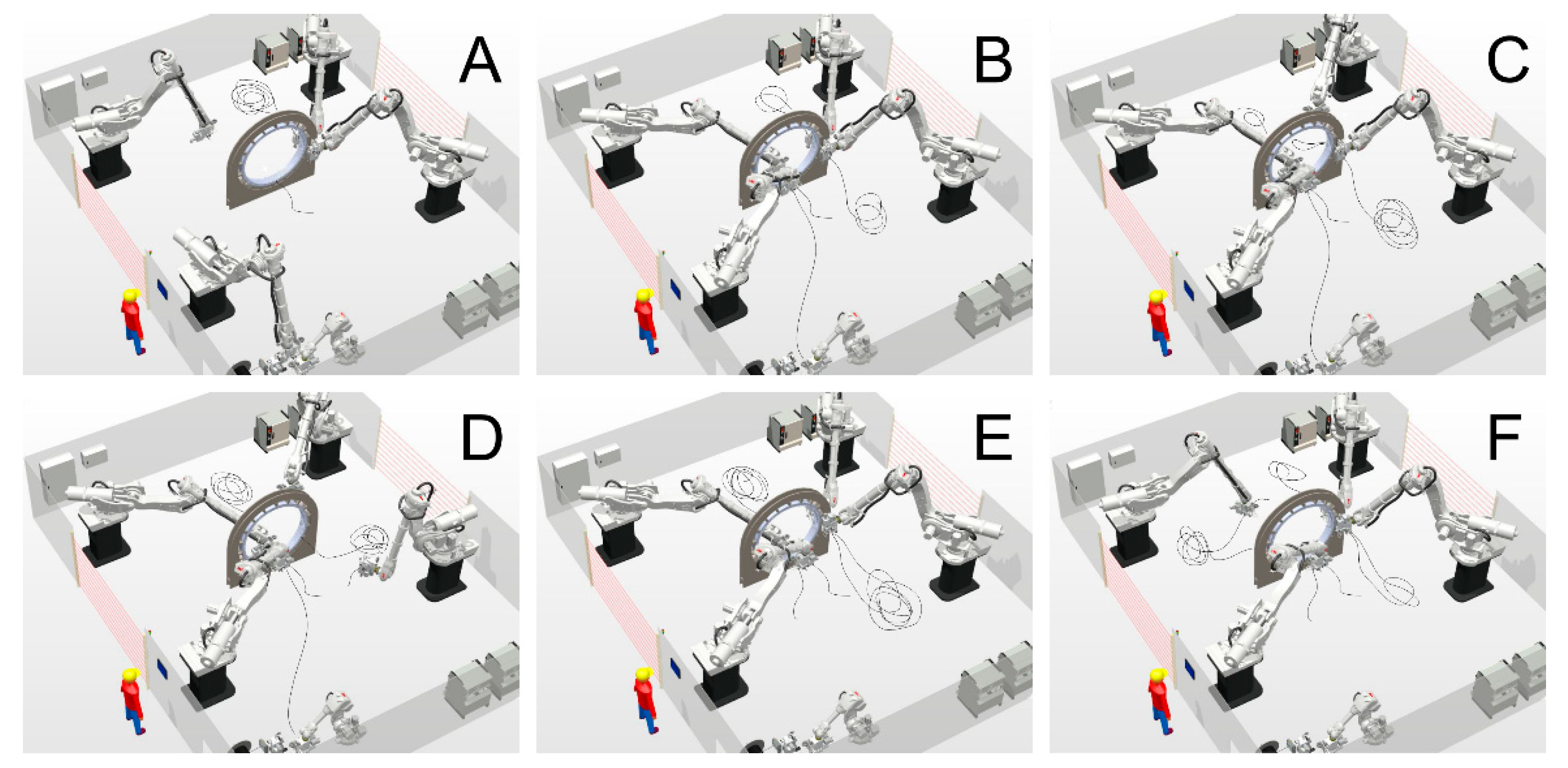
Figure 5.
Graphical illustrations of the simulated robotized stator cable winding process with S2c, with winding robot pair one (RP1) to the left and winding robot pair two (RP2) to the right. The process is repeated until the full stator is wound. Note that the cable positioning is only from process illustration. (A) The lower robot in RP1 fetches a prepared cable from the drum, and RP2 is positioned to start feeding through a new slot hole. (B) RP1 is positioned to start feeding through a new slot hole and RP2 has started to feed cable. (C) RP1 has started to feed cable and the lower robot in RP2 is pulling the end winding as the upper robot has dropped the cable. (D) RP1 has fed most of the cable, and the lower robot in RP2 is finding the cable end by feeding the cable backwards out on the floor. (E) The lower robot in RP1 has dropped the cable as it is cut off at the drum, and RP2 is positioned to feed through a new slot hole. (F) The upper robot in RP1 is finding the cable by feeding the cable backwards out on the floor end and RP2 has started to feed the cable.

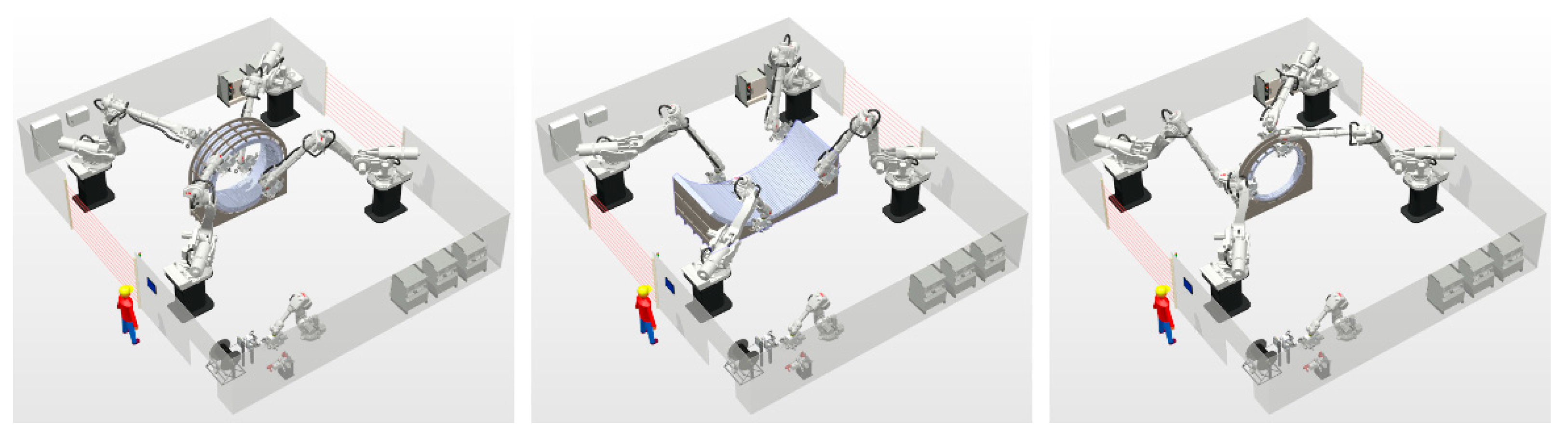
Figure 6.
Graphical illustrations from simulations of the robotized stator cable winding of the larger rotating electric machine designs S1a (left), S1b (middle) and S1c (right).
Figure 6.
Graphical illustrations from simulations of the robotized stator cable winding of the larger rotating electric machine designs S1a (left), S1b (middle) and S1c (right).

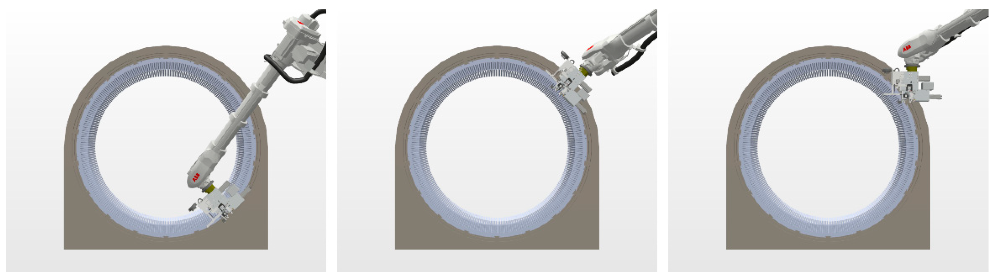
Figure 7.
Robot tool positioning during winding, with the cable feeder directed radially from the inside of the stator at lower slots (left), radially from the outside of the stator at higher slots (middle) and vertical for cable dropping (right).
Figure 7.
Robot tool positioning during winding, with the cable feeder directed radially from the inside of the stator at lower slots (left), radially from the outside of the stator at higher slots (middle) and vertical for cable dropping (right).

Figure 8.
Estimated robot winding cycle time results for complete S1a–c stators in winding development scenarios W0–2, divided into feeding time, other time and WOCS time.
Figure 8.
Estimated robot winding cycle time results for complete S1a–c stators in winding development scenarios W0–2, divided into feeding time, other time and WOCS time.

Figure 9.
Estimated assembly costs for manual stator cable winding relative to robotized stator cable winding of S1a–c in winding development scenarios W0–2, for P1–2.
Figure 9.
Estimated assembly costs for manual stator cable winding relative to robotized stator cable winding of S1a–c in winding development scenarios W0–2, for P1–2.

Figure 10.
Graphical illustrations from simulations of the robotized stator cable winding with one smaller rotating electric machine designs S2a (left) and S2b (middle), and of the extended robot cell for winding two S2 machines simultaneously (right).
Figure 10.
Graphical illustrations from simulations of the robotized stator cable winding with one smaller rotating electric machine designs S2a (left) and S2b (middle), and of the extended robot cell for winding two S2 machines simultaneously (right).

Figure 11.
Robot tool positioning during winding, with the cable feeder directed radially from the outside of S2a (left) and vertically perpendicular from above of S2b (right).
Figure 11.
Robot tool positioning during winding, with the cable feeder directed radially from the outside of S2a (left) and vertically perpendicular from above of S2b (right).

Figure 12.
Estimated robot winding cycle time results for complete S2a–b stators in winding development scenarios W0–2, divided into feeding time, other time and WOCS time.
Figure 12.
Estimated robot winding cycle time results for complete S2a–b stators in winding development scenarios W0–2, divided into feeding time, other time and WOCS time.

Figure 13.
Estimated assembly costs for manual stator cable winding and conventional automated stator winding references scenarios from [4] relative to robotized stator cable winding of S2a–b in winding development scenarios W0–2, for P1–2 with manual winding and for P1 with conventional automation. References 1–2 are highly automated high throughput insert winding and hairpin winding, and Reference 3 is simpler lower throughput insert winding.

Figure 14.
Graphical illustrations from simulations of robotized stator cable winding of two smaller rotating electric machine designs S2a (left) and a linear UU Wave Energy Converter stator section (right) in the robot cell developed for the larger rotating electric machine designs S1a–c.
Figure 14.
Graphical illustrations from simulations of robotized stator cable winding of two smaller rotating electric machine designs S2a (left) and a linear UU Wave Energy Converter stator section (right) in the robot cell developed for the larger rotating electric machine designs S1a–c.

Figure 15.
Illustrated extension to rotating stator designs of the GUI previously implemented on an operator touch screen for control, supervision and service of the robot stator cable winding process.
Figure 15.
Illustrated extension to rotating stator designs of the GUI previously implemented on an operator touch screen for control, supervision and service of the robot stator cable winding process.


Table 1.
Geometric and winding characteristics for S1a–c.
| Parameter | S1a | S1b | S1c |
|---|---|---|---|
| inner diameter | 2054 mm | 4500 mm | 1635 mm |
| outer diameter | 2367 mm | 4800 mm | 1800 mm |
| slot length | 848 mm | 1840 mm | 197 mm |
| end winding | 320 mm | 300 mm | 50 mm |
| slots | 270 | 225 | 420 |
| feeds per slot | 6 | 6 | 6 |
| electric phases | 3 | 3 | 3 |
| cables per phase | 6 | 18 | 6 |
| winding pattern | wave | wave | wave |
| cable diameter | 13.6 mm | 25 mm | 7.2 mm |
| stator sections | 1 | 3 | 1 |
| manual winding | 160 h | 120 h | 30 h |
| winding personnel | 5 | 2 | 2 |
| floor space 1 | 45 m2 | 60 m2 | 30 m2 |
1 Rough estimations for the assembly cost analysis in this work only, per manual winding station.
Table 2.
Geometric and winding characteristics for S2a–b.
| Parameter | S2a | S2b |
|---|---|---|
| inner diameter | 154 mm | 120 mm |
| outer diameter | 270 mm | 260 mm |
| slot length | 130 mm | 118 mm |
| end winding | 130 mm 1 | 200 mm |
| slots | 12 | 30 |
| feeds per slot | 20 | 8 |
| electric phases | 3 | 3 |
| cables per phase | 2 | 10 |
| winding pattern | concentrated | distributed |
| cable diameter | 6.2 mm | 4.7 mm |
| stator sections | 1 | 1 |
| manual winding | 6 h | 10 h |
| winding personnel | 2 | 2 |
| floor space 2 | 10 m2 | 10 m2 |
1 Include winding through the rotor end plates and bearings. 2 Rough estimations for the assembly cost analysis in this work only, per manual winding station.
Publisher’s Note: MDPI stays neutral with regard to jurisdictional claims in published maps and institutional affiliations. |
© 2022 by the author. Licensee MDPI, Basel, Switzerland. This article is an open access article distributed under the terms and conditions of the Creative Commons Attribution (CC BY) license (https://creativecommons.org/licenses/by/4.0/).
Share and Cite
MDPI and ACS Style
Hultman, E. Introducing Robotized Stator Cable Winding to Rotating Electric Machines. Machines 2022, 10, 695. https://doi.org/10.3390/machines10080695
AMA Style
Hultman E. Introducing Robotized Stator Cable Winding to Rotating Electric Machines. Machines. 2022; 10(8):695. https://doi.org/10.3390/machines10080695
Chicago/Turabian StyleHultman, Erik. 2022. "Introducing Robotized Stator Cable Winding to Rotating Electric Machines" Machines 10, no. 8: 695. https://doi.org/10.3390/machines10080695
Note that from the first issue of 2016, this journal uses article numbers instead of page numbers. See further details here.