Article

Active Control of Torsional Vibration during Mode Switching of Hybrid Powertrain Based on Adaptive Model Reference

1
School of Intelligent Manufacturing, Chongqing University of Arts and Sciences, Chongqing 402160, China
2
School of Mechanical and Electrical Engineering, Chongqing Jiaotong University, Chongqing 400074, China
3
School of Mechanical Engineering, Beijing Institute of Technology, Beijing 100081, China
*
Author to whom correspondence should be addressed.
Machines 2022, 10(8), 647; https://doi.org/10.3390/machines10080647
Submission received: 4 July 2022 / Revised: 27 July 2022 / Accepted: 31 July 2022 / Published: 4 August 2022
(This article belongs to the Special Issue Noise and Vibration Control in Dynamic Systems)

Abstract

:
When the energy management and coordinated control of the hybrid electric vehicle power system are not proper, torsional vibration problems will occur in various working states, especially in the mode switching process. These vibrations will affect the comfort, economy and emission of vehicles. In order to suppress the torsional vibration, this paper studied the active vibration control algorithm for the hybrid powertrains under the switching process of pure electric mode to hybrid mode. Primarily, the clutch combination process was divided into five stages and the dynamic models of the transmission system of each stage were established, respectively. Moreover, the principle of model reference adaptive control was analyzed. The applicability of the method to the torsional vibration of the driveline during mode switching was described. Furthermore, the clutch free displacement phase was used as the reference model. A model reference adaptive torsional vibration controller was built based on the controlled model. Finally, the efficacy of this active method for vibration reduction was simulated. The simulation results show that torsional vibration is most likely to occur in the speed coordination stage and the full participation stage. In these two stages, the designed controller can reduce the fluctuation of motor speed by 93.2% and 97.5%, respectively, the engine speed by 79.6% and 77.4%, respectively, the motor acceleration by 96.7% and 82.3%, respectively, and the engine acceleration by 88.9% and 82.3%, respectively. In addition, the controller can reduce the impact degree of the transmission system to within ±1 m/s3.

1. Introduction and State-of-Art

Compared with traditional fuel vehicles, hybrid vehicles have more advantages in economy and power. But at the same time, there are more challenges in driving comfort and safety. Power transmission system is the core component of hybrid drive, and its complexity is mainly determined by two aspects [1,2]. Firstly, when the hybrid vehicle starts, shifts gears, brakes, mode switching caused by energy management strategy, etc., the transmission system is stimulated by multiple sources, which will produce a great dynamic load. Torsional vibration of transmission system is prominent. Secondly, the engine is the main source of torsional vibration of the transmission system. If the structural parameters of the transmission system are not designed properly, noise and resonance will be generated, and the shock absorber will be damaged seriously. At the same time, although the motor in the hybrid car can speed up the response, it also leads to the instability of power transmission, which affects the reliability and durability of the gearbox system components. Therefore, the torsional vibration control of the transmission system of hybrid electric vehicle becomes an urgent problem to be solved.
As the P2 hybrid electric vehicle has the particularity of two clutches, the motor can be used as the power source of the transmission system and start the engine. During the mode switching from pure electric power to hybrid power, the motor drives the clutch driven disk to move through the driving shaft. During the clutch combination process, the engine crankshaft is first dragged to idle speed, then coordinated with the engine driving speed until the clutch is fully combined, and finally the speed synchronization is achieved to drive the automobile together. In the above process, due to the coordinated output of multiple power sources and the discontinuity, nonlinearity and uncertainty of the clutch system, various torsional vibration problems will occur in the transmission system. Therefore, the vibration suppression problem centered on power quality optimization caused by frequent switching of multiple power sources and modes needs further study.
The active damping control method is widely studied to control the torsional vibration of hybrid electric vehicles. Related research focuses on the following two aspects:
i.
Active vibration reduction by feedback control and frequency correction
Many scholars used series correction or feedback control method to produce damping effect to reduce the vibration near the resonance frequency. Valenzuela [3] made active damping injection through the principle of zero-pole cancellation in frequency domain, which effectively reduced the vibration transmissibility near the resonance frequency. Liu [4] proposed a method of combining reference adaptive control with pole assignment to control the torsional vibration under the condition of parameter uncertainty, and suppressed the torque ripple of the output shaft under the impact condition. Fu [5] and Zhang [6], respectively, adopt a Linear Quadratic Regulator (LQR) with a parameter estimation to control the body shaking and torsional vibration of electric vehicles during rapid acceleration. Berri [7] took the engine speed as the feedback input, and improved the damping and attenuation effect of the resonance point of the transmission system by introducing band-pass filter series correction. Zhao et al. [8] put forward a control scheme of active vibration reduction and feedforward correction based on feedback control to effectively attenuate the fluctuation impact of an EV mode hybrid transmission system. Zhou [9] proposed a feedforward–feedback control strategy considering nonlinear backlash, which can be regarded as an effective approach to attenuate driveline oscillation and thus improve ride comfort on launch condition.
In addition, feedback control based on time domain index has also attracted much attention. In this method, the difference between the rotational speed of the power source and the rotational speed of the vehicle is used as the feedback signal, and the minimization of the rotational speed difference is used as the control objective to set the active damping compensation torque. Syed [1] and Walker [10] commanded the motor to output compensation torque to eliminate the speed difference, thus realizing active damping. Kou [11] Li also designed a sliding mode controller based on the principle of speed difference compensation. The speed difference was transmitted to the motor through the positive feedback controller, and the motor was ordered to output the corresponding compensation torque. This damping control method generates generalized damping to solve the weak damping problem of transmission system. Gao et al. [12] proposed a sliding mode controller to coordinate the dynamic performance for HEV during mode switching. Chao Yang [13] studied an adaptive dual-loop control framework for the clutch engagement in a parallel HEV, which not only determined the engagement time of the clutch, but also effectively controlled the vehicle jerk.
ii.
Dynamic coordinated control of torque disturbance compensation
In essence, the dynamic coordinated control of torque disturbance is to compensate for the slow response of engine torque through the quick response of motor torque, and its basic principle is to use the torque of multiple power sources to peak load and valley load [14]. Tomura [15] and Chen [16] produced compensation torque through the power coupling of the motor to offset the pulsating torque of the internal combustion engine. The torque of internal combustion engine was effectively controlled by using the observer with crank speed as input. The vibration problem when the engine starts and stops in the neutral state was solved. Yong [17] designed an anti-vibration impact controller, which is composed of an active damping method to generate the reverse torque opposite to the vibration phase and a torque profile method to limit the torque gradient. Similar research has been conducted by Morandin et al. [18] by controlling the permanent magnet synchronous motor as an active torque damping system. The reverse torque sequence is applied to the engine crankshaft to smooth the rotation speed oscillation.
Multi-power source coordinated control is mainly to used ensure the power and smooth performance of the vehicle before and after the state switch. Crolla et al. [19,20] discussed the torsional vibration in the process of mode switching. The fluctuation in engine output torque was predicted. The least square method was used to identify the components’ parameters, thus reasonably restraining the torque fluctuation. Similarly, Cauet et al. adopted linear variable parameter control [21], model reference control [22], waveform superposition control strategy [23] and model prediction control [24,25] to reduce the engine torque ripple by controlling the torque of the permanent magnet synchronous motor. Wang [26] designed the optimal starting control strategy of the engine based on a dynamic programing algorithm. The ride comfort of HEV during mode switching is optimized.
The above studies have proposed effective solutions to the torsional vibration problems of HEV. The existing feedback correction vibration suppression strategy can suppress the torsional vibration of a hybrid power transmission system to a certain extent. However, most of them are only effective for vibration suppression in specific or limited frequency bands. Although torque compensation vibration damping control can also play a certain damping effect. As the exciting force, the engine torque fluctuation and the multi-working conditions and parameter uncertainty of the transmission system make the hybrid transmission system show strong nonlinear characteristics. Therefore, considering the nonlinear characteristics, the vibration suppression of a hybrid vehicle with wide-band adaptive parameters should be further investigated. In this paper, an adaptive torsional vibration active control method is studied to dampen the driveline vibration for P2 hybrid electric powertrains during the switching process of EV-HEV.
This paper is organized as follows: In Section 2, the architecture and dynamic modeling of the hybrid vehicle drive system is constructed. In Section 3, the principle of Model Reference Adaptive Control (MRAC) was analyzed. The applicability of MRAC to the torsional vibration of the driveline during mode switching was described. Furthermore, the clutch free displacement phase was used as the reference model. A model reference adaptive torsional vibration controller was built based on the controlled model. In Section 4, the simulation of the adaptive torsional vibration control algorithm is performed and its stability is evaluated. In Section 5, conclusions and future works are discussed.

2. Powertrain Modeling

2.1. P2 Hybrid Powertrain Architecture

In this paper, the P2 configuration hybrid electric vehicle without a dual-mass flywheel is taken as the research object. Its structure is shown in Figure 1. The system mainly includes a traditional engine, a reversible motor that can be used as both a motor and a generator, two clutches and an automatic transmission. It is possible to cut off the power output of the engine or prevent the motor torque from being transmitted to the engine by controlling the separation of clutch 1. Clutch 2, which is connected to the automatic transmission, can switch between different states according to the gear position.

2.2. Dynamic Model

In order to focus on the dynamic characteristics of both ends of the clutch plate and simplify the design of the controller, according to the characteristics of the mode switching process, the transmission system model is adjusted to only consider the engine, clutch and motor, as shown in Figure 2.
Where Je and Jm are the moment of inertia of the engine part and the motor part, respectively; ωe and ωm represent engine speed and motor speed, respectively; Te and Tm represent engine torque and motor torque, respectively; Tr is the equivalent load torque of the motor output shaft, which is distributed by the energy management system according to the driver’s demand; Tc is the maximum friction torque that the clutch can provide, which can be expressed as follows:
T c = μ c R c F b N c s i g n ( ω m ω e )
where μc, Rc, Fb and Nc are the friction coefficient, effective radius, number and pressure of clutch plates, respectively.
It can be known from Formula (1). that when the input torque of the clutch is greater than the maximum friction torque, the transmission torque of the clutch is equal to the maximum friction torque. When the input torque of the clutch is less than the maximum friction torque, the transmission torque of the clutch is equal to the input torque.
In the process of mode conversion, the engine needs to be engaged into the power train through the clutch slip phase. At the same time, the motor must increase its output torque to start the engine and provide driving force. Mode conversion performance depends on clutch engagement. Therefore, in order to better describe the powertrain model in this process, this paper divides the clutch engagement into five stages, as shown in Figure 3.
i.
Clutch free displacement stage
The model of clutch free displacement stage is shown in Figure 4. At this stage, the driven disc of the clutch starts to move, but still does not contact with the driving disc of the clutch. The motor outputs torque and drives the clutch driven disk to rotate through the transmission shaft. At this stage, the engine speed is zero. Therefore, the dynamic model of the transmission system can be written as:
J m ω ˙ m = T m T r
ii.
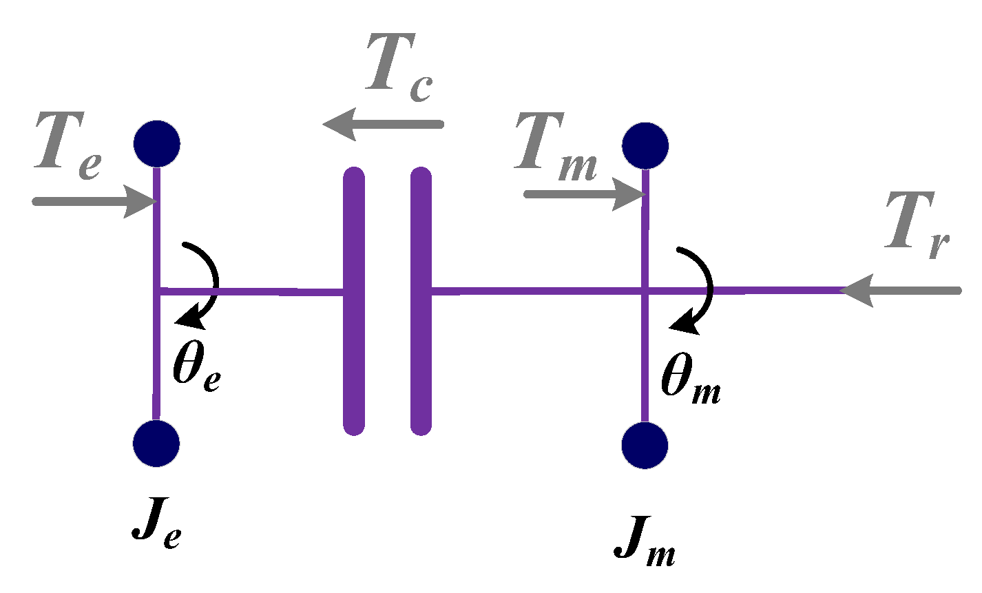
The first stage of clutch slip
A first stage model of clutch slip is shown in Figure 5. The clutch driven plate and the driving plate begin to contact and slip. However, since the starting resistance torque of the engine transmitted at this time is still greater than the clutch torque, the clutch driven plate on the motor side is rotating, while the clutch driving plate on the engine side is still in a stationary state. The engine is still stationary. The powertrain dynamics model for this phase is:
J m ω ˙ m = T m T r T c
iii.
The second stage of clutch slip
The second stage model of clutch slip is shown in Figure 6. When the torque transmitted by the clutch gradually increases to exceed the starting resistance torque of the engine, the crankshaft of the engine is driven to rotate when the clutch slips. The engine is kept in a non-ignition state until it reaches idle speed. Tsr represents the starting resistance torque of the engine, which can be obtained by referring to the table of steady-state experimental characteristics of the engine. The transmission system dynamics model of the above process is as follows:
{ J e ω ˙ e = T c T s r J m ω ˙ m = T m T r T c
iv.
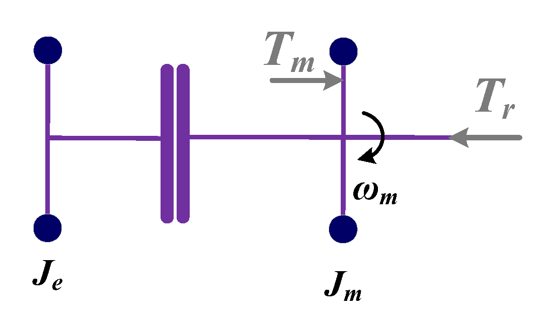
Speed synchronization stage
The synchronization phase model is shown in Figure 7. When the engine speed exceeds the idle speed, the engine will receive the ignition command from the advanced controller and begin to output torque. At the same time, the clutch actuator is controlled to push the clutch driven disk. At this stage, the engine speed is still lower than the motor speed, so there is still a speed difference between the two sides of the clutch. This phase continues until the engine speed is coordinated with the clutch engagement speed. The dynamic model of the transmission system in this stage is:
{ J e ω ˙ e = T e + T c J m ω ˙ m = T m T r T c
v.
Full participation stage
The full-scale participation model is shown in Figure 8. When the speed difference between the engine and the motor drops to a given range, the clutch is engaged at the maximum engagement speed, and the engine will start to actively output driving torque. At this time, the mode switching process from pure electric drive to hybrid drive is completed by the joint output torque of engine and motor. The dynamic model of the transmission system at this stage is:
( J e + J m ) ω ˙ m = T e + T m T r
For the hybrid transmission system studied in this paper, as a result of the rotating speeds of the friction plates at both ends of the clutch being different in the mode switching process, and the clutch having two degrees of freedom, the speed at both ends of the clutch will be used as two output variables of the control system in the sliding process. According to the established dynamic model, it can be known that in the process of power conversion, the input variables of the control system include motor torque, engine torque and clutch torque. At this time, the number of input variables of the system is greater than the number of output variables, showing an overdrive system state, which theoretically has infinite solutions. Therefore, appropriate constraints should be added, and a reasonable control model should be constructed to adjust the input variables, so that the system tends to be stable. When the speed phase is switched to the full participation phase, the friction torque of the clutch is switched from sliding friction torque to static friction torque, and its nonlinear characteristics are introduced into the whole transmission system. If the control is unreasonable, the friction torque will be discontinuous and abrupt, which will affect the stability of the transmission system.

3. Active Control Algorithm

3.1. Basic Principle of Controller

The model used in this paper refers to MRAC (Model Reference Adaptive Control), according to which the torsional vibration and the impact of the transmission system during mode switching can be controlled. The structure and working mechanism of the model reference adaptive control system are shown in Figure 9. The system mainly includes three parts, namely the reference model, the adjustable system and the adaptive mechanism. Their respective working principles are as follows:
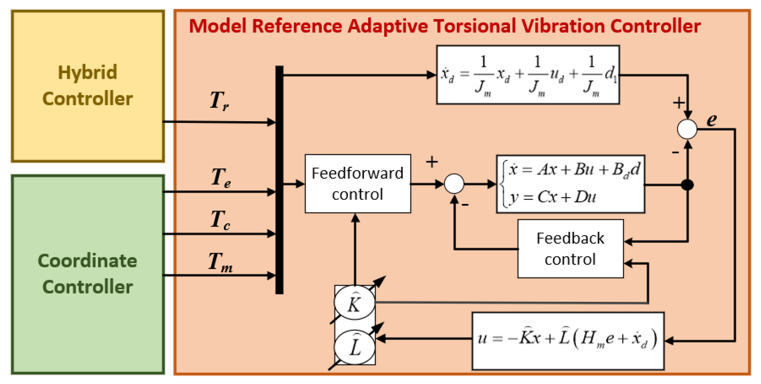
  • Reference model refers to an ideal system with a stable structure and constant parameters, and its output represents the expected performance. Under the influence of the reference input r of the control system, the output y of the model is set to adjust the output state of the controlled object in real time according to the ideal output ym of the reference model.
  • The adjustable system consists of the controlled object, the front controller and the feedback controller. The state characteristic requirements of the adjustable system are given by reference models such as overshoot, damping performance, transition time and passband.
  • Affected by external influences and random changes of the internal structure of the system (parameter deviation, etc.), there will be a deviation e between the actual output y of the controlled object and the ideal output ym. When the adaptive mechanism receives the speed deviation signal, it will adjust the control parameters of the control system according to the pre-designed adaptive law. As such, this will either mobilize the feedforward controller and feedback controller, or generate the auxiliary input to eliminate errors, so that the process output is consistent with the reference model output.
After in-depth analysis of the dynamic characteristics of the transmission system with pure electric-hybrid mode switching, it can be known that the transmission system is most prone to impact when the clutch slips in the second stage and the speed synchronization stage is switched to the full participation stage. Therefore, the control goal of this paper is to ensure the smooth operation of the transmission system during the engine start-up and clutch sliding. When the ideal state is mode switching, the dynamic performance of the vehicle is exactly the same as that of the vehicle in pure electric mode under the same external conditions. Therefore, in this paper, the reference model is set as the transmission system dynamics model in the clutch free displacement stage.

3.2. The Scheme of Torsional Vibration Controller

The torsional vibration controller consists of four parts as shown in Figure 10. The torsional vibration controller receives the engine torque Te, the clutch friction torque Tc and the motor torque Tm measured from the mode switching coordination controller, the target torque Tr sent by the hybrid controller. When the motor controller receives the target torque command and the target speed command from the hybrid controller, the hybrid adaptive torsional vibration controller is executed and a control torque command is sent to the motor.

3.2.1. Derivation of Controller

Set the dynamic model of clutch free displacement stage as the reference model of this controller. The dynamic equation of the reference model is as follows:
J m ω ˙ m = T m T r
where ωm is the required rotational speed calculated by the reference model; Tm is the equivalent driver demand torque.
Let the state variable xd = ωm, the input variable ud = Tm, the output variable yd = ωm, and the disturbance variable d1 = −Tr. Then the state space equation of the reference model is:
x ˙ d = 1 J m x d + 1 J m u d + 1 J m d 1
Given the actual state x and ideal state xd of the system, the tracking error of the system and its reciprocal can be obtained as follows:
{ e = x x d e ˙ = x ˙ x ˙ d
The state space equation of the control system is brought into the Equation (9). The dynamic error equation of the system can be obtained as follows:
e ˙ = A x + B u x ˙ d
The matrix Hm∈R2×2 is defined as any Hurwitz matrix and the above formula can be transformed into:
e ˙ = H m e + B [ u + K * x L * ( H m e + x ˙ d ) ]
where K*∈R2×2 and L*∈R2×2 and their relationship is shown in the following formula:
{ B K * = A B L * = I
In the formula, I∈R2×2 is identity matrix.
The control rate and dynamic error of the control system can be obtained from Equation (11) as follows:
u = K * x + L * ( H m e + x ˙ d )
{ e ˙ = H m e lim t e ( t ) = 0
In the control rate, neither K* nor L* can be directly obtained by calculation. Therefore, it is necessary to estimate the unknown parameters of the system control rate, and the estimation error is:
{ K ˜ = K K * L ˜ = L L *
where, K and L are the estimated values of K* and L*, respectively.
By replacing the unknown parameters of the system in the control rate with their estimated values, the adaptive control rate can be obtained as follows:
u = K x + L ( H m e + x ˙ d )
By combining Formulas (10) and (11) and Formulas (15) and (16), the dynamic error equation of the system can be rewritten as:
e ˙ = H m e + L * 1 [ K ˜ x + L ˜ ( H m e + x ˙ d ) ]
The matrix ω is defined as the Formula (18). When the matrix L* is positive or negative, ρ = 1. So Ω is always a positive matrix.
Ω = inv ( L * ) ρ

3.2.2. Proof of Stability

In this paper, Lyapinov direct method is used to prove the stability of the adaptive control rate. In order to build a more effective parameter regulation system and ensure that the controller eventually tends to converge stably, it is important to match a reasonable Lyapinov function for the controller. The Lyapinov function defined in this paper is:
V = e T P e + tr ( K ˜ T Ω K ˜ + L ˜ T Ω L ˜ )
where P and Ω are positive definite matrices; tr is the trace of the matrix.
According to Hurwitz matrix properties, it can be concluded that:
H m T P + P H m = Q
where Q is a positive definite symmetric matrix, and it is arbitrary.
The reciprocal of Lyapinov matrix can be obtained by taking derivative of Equation (19) as follows:
V ˙ = e ˙ T P e + e T P e ˙ + d dt tr ( K ˜ T Ω K ˜ + L ˜ T Ω L ˜ )
The Formula (20) is brought into the Formula (21) to obtain that:
V ˙ = { H m e + L * 1 [ x + L ˜ ( H m e + x ˙ d ) ] } T P e + P { H m e + L * 1 [ K ˜ x + L ˜ ( H m e + x ˙ d ) ] } + d dt tr ( K ˜ T Ω K ˜ + L ˜ T Ω L ˜ )
After the Equation (22) is simplified:
V ˙ = e T ( H m T + P H m ) e + 2 e T P L * 1 [ K ˜ x + L ˜ ( H m e + x ˙ d ) ] + d dt tr ( K ˜ T Ω K ˜ + L ˜ T Ω L ˜ )
According to the properties of matrix trace derivation, it can be obtained that:
d dt tr ( K ˜ T Ω K ˜ + L ˜ T Ω L ˜ ) = 2 tr ( K ˜ T Ω K ˜ + L ˜ T Ω L ˜ )
The Formula (24) is brought into the Formula (23) to obtain that:
V ˙ = e T ( H m T + P H m ) e + 2 e T P L * 1 [ K ˜ x + L ˜ ( H m e + x ˙ d ) ] + 2 tr ( K ˜ T Ω K ˜ + L ˜ T Ω L ˜ )
According to the properties of matrix trace and confrontation matrix, it can be obtained that:
e T P L * 1 K ˜ x = tr ( K ˜ T L * 1 P e x T )
e T P L * 1 L ˜ ( H m e + x ˙ d ) = tr [ L ˜ T L * 1 P e ( H m e + x ˙ d ) T ]
The reciprocal of the final Lyapinov matrix can be obtained by bringing Formula (26) and Formula (27) into Formula (25) as follows:
V ˙ = e T Q e + 2 tr ( K ˜ T Ω K ˜ + L ˜ T Ω L ˜ K ˜ T L * 1 P e x T ) + 2 tr [ L ˜ L * 1 P e ( H m e + x ˙ d ) T ]
To ensure that the V ˙ is negative, the change laws K and L are controlled as follows:
K ˙ = P e x T sign ( ρ )
L ˙ = P e ( H m e + x ˙ d ) T sign ( ρ )
Vertical Formulas (28)–(30) can obtain that:
V ˙ e T Q e 0
As V 0 and V ˙ 0 , the adaptive control law designed in this paper can keep the variable parameters and state variables of the controller system bounded in finite time. The tracking error approaches zero, and the control system tends to be stable.

4. Result and Discussion

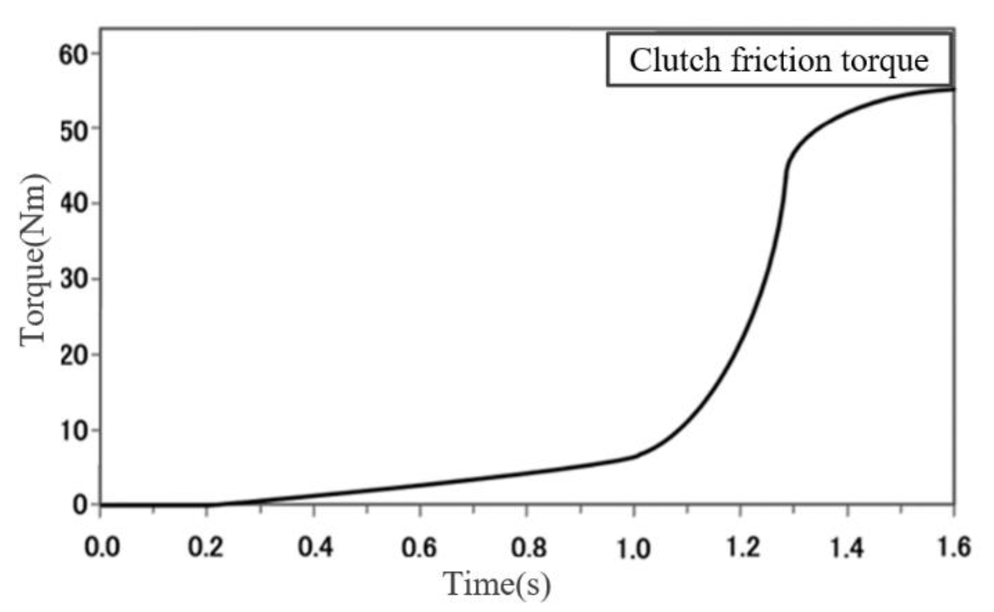
4.1. Simulation Environments

The parameters of the model are shown in Table 1. The engine torsional vibration model and clutch friction model used in this simulation are built in AMEsim. Clutch friction torque is shown in Figure 11. Based on the traditional coordinated controller, a model reference adaptive controller is built in Simulink. Through the joint simulation of AMEsim and Simulink, the damping effect of the controller designed in this chapter can be verified. This is achieved by the following: setting the simulation condition to enter the mode switching stage from 0 s; setting the equivalent initial speed of the motor output shaft to 1000 r/min; and setting the idle speed of the engine to 550 r/min. By comparing the speed and torque of motor and engine with or without torsional vibration control in the simulation results, the control effect is determined.

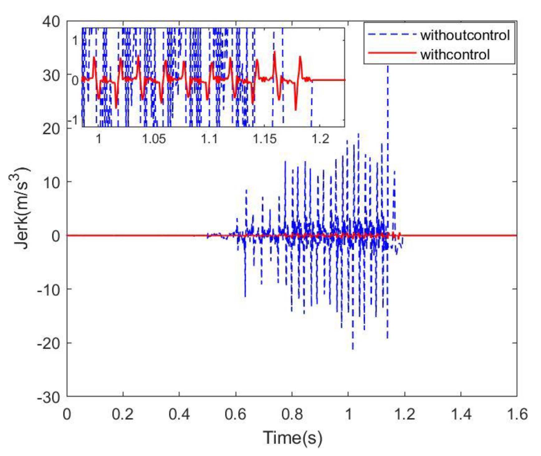
4.2. Simulation Results

The simulation results of output torque of the engine and motor are shown in Figure 12. In the process of mode switching, the target torque of the engine and the driving motor are directly given by the energy management strategy, meaning 0–0.2 s is the clutch free displacement stage. As the driven disc of the clutch has not made contact with the driving disc at this stage, the values of the friction torque of the engine and the clutch have not changed. As the clutch driven disk continues to move, the clutch driven disk begins to slip. From 0.2 s onwards, the friction torque of the clutch gradually increases, and the motor speed begins to fluctuate slightly under this influence. Due to the static friction, the driving disk has not moved yet, so the speed of the engine output shaft remains at zero. After 0.3 s, the clutch driving disc starts to move and drives the engine crankshaft to rotate to idle speed. At this stage, the clutch and the engine crankshaft are equivalent to the extra load of the motor. Therefore, in order to achieve the total torque of the vehicle, the motor torque increases to ensure the power output.
After the engine speed rises to 550 r/min, the engine ignites and burns to start outputting torque. It can be seen from Figure 13 that the engine speed after control rises to idle speed slowly, so the engine ignition time after control is later than that before control. The torque comparison diagram of the corresponding stage shows that the engine output torque will fluctuate greatly before control due to the non-uniformity of combustion after ignition. Under the action of the controller, the motor outputs compensation torque to compensate the torque fluctuation in the engine and clutch. Therefore, the fluctuation in engine torque after control is obviously attenuated.
In the phase of speed coordination, the engine speed is gradually increased to coordinate with the motor speed under the interaction of friction discs at both ends of the clutch. The uneven transmission torque of the clutch is caused by the fluctuation in engine output torque, resulting in the fluctuation in motor output torque. After this stage control, the maximum deviation in motor speed decreased by 93.2% compared with that before control. After control, the maximum deviation in engine speed decreased by 79.6% compared with that before control. When the difference between engine speed and motor speed drops to 50 r/min, the clutch is fully engaged and enters the full participation stage. Furthermore, the engine motor outputs torque according to the instructions distributed by the energy management system. At this stage, the engine speed is equal to the motor speed. After the control, the maximum deviation of rotational speed decreased by 97.5% compared with that before the control. The maximum deviation in engine torque after control is 77.4% lower than that before control.
Comparison of simulation results of engine and motor acceleration is shown in Figure 14. It can be seen that the effective control rate of the controller to the maximum deviation in engine acceleration fluctuation in the speed coordination stage and the speed synchronization stage is 88.9% and 82.3%, respectively. Before the speed synchronization stage, the control efficiency of the controller to the maximum deviation of motor acceleration reached 96.7%. After entering the speed synchronization stage, the amplitude of motor acceleration fluctuation increased due to the influence of engine output torque fluctuation, but the control efficiency still reached more than 80%. The analysis of the effective control rate of the engine-motor unit in the controller speed coordination stage and full participation stage is shown in Table 2. As shown in Figure 15, it can be observed that after the engine speed is increased to idle speed, the controller can reduce the impact of the transmission system to within ±1 m/s3, reaching the German recommended impact value of ±10 m/s3.
To sum up, in the time domain, the model reference adaptive controller built in this paper has a good control effect on the fluctuation in engine output torque and the fluctuation in engine and motor speed and acceleration. Then the torque fluctuation in the input end of the transmission is attenuated, thus achieving the purpose of vibration reduction in the whole transmission system.
Except from the perspective of time domain, the performance of the controller can also be measured from the perspective of frequency domain. Fourier transform is performed on the rotation speeds of the engine and the motor to obtain a spectrum, as shown in Figure 16. In the figure, the x axis is time, and the y axis and the color bar represent frequency. The larger the value of the y axis is, and the closer the color is to blue, the more this indicates that the fluctuation amplitude of the rotating speed is smaller. On the contrary, the smaller the value of the y axis and the closer color is to red, the more this indicates that the fluctuation in the rotating speed is more severe. Through the observation of comparison charts for the A and B groups, it can be seen that the engine speed after 0.8 s control is closer to the blue range, which indicates that the controller can effectively control the engine speed fluctuation in the speed synchronization stage and the full participation stage. The blue range of the motor speed spectrum is larger after 0.3 s control, and in particular, the torsional vibration attenuation at the motor is more obvious in the speed synchronization stage after the engine is increased to idle speed. The results show that the designed model reference adaptive controller can effectively improve the ride comfort of the vehicle transmission system in the process of mode switching.

5. Conclusions and Future Work

An adaptive active vibration control algorithm that dampens the powertrain vibration is proposed in this work for hybrid electric vehicles during the mode switching process. Firstly, the hybrid system model of EV-HEV mode switching process is established. The clutch engagement process is divided into five stages, and the dynamic equilibrium equation of each stage is established. Secondly, the dynamic model of a clutch free displacement stage is set as the reference model, and the model reference adaptive torsional vibration controller is built based on the multi-stage dynamic model of a mode switching process. Finally, the control effects of the controller on the speed and torque of the transmission system in time domain and frequency domain are compared and analyzed. The simulation results show that in the process of mode switching, the most prone stages of torsional vibration are the speed coordination stage and the speed synchronization stage. In these two stages, the designed controller can reduce the fluctuation in motor speed by 93.2% and 97.5%, respectively, the engine speed by 79.6% and 77.4%, respectively, the motor acceleration by 96.7% and 82.3%, respectively, and the engine acceleration by 88.9% and 82.3%, respectively. In addition, the controller can reduce the impact degree of the transmission system to within ±1 m/s3, reaching the recommended value of impact degree in Germany. Besides, the controller can also significantly reduce the speed fluctuation in both the engine and motor in spectrum analysis.
On the basis of the coordinated control of power in the process of mode switching, this paper further discusses the torsional vibration in a transmission system caused by the fluctuation in engine output torque. Compared with common PID control and sliding mode control for dynamic coordination [12,13], adding adaptive model reference adaptive control can further attenuate the transmission system oscillation caused by the torque fluctuation in the engine. The effective control rate of motor speed vibration is over 90%, and the effective control rate of engine speed vibration is over 70%. This is a further study on the torsional vibration control of hybrid electric vehicle transmission system.
Although the parameter uncertainty of the model and the uncertainties of real-time traffic might bring some difficulties for the application of the AMRC algorithm, using the AMRC algorithm is still a potential method for the vibration control strategy of hybrid electric vehicles from an academic point of view. In the following areas, additional studies may be carried out: the multi-working conditions; and wide speed range torsional vibration reduction problems of the hybrid powertrain under mode switching will be considered; a torsional vibration control strategy of hybrid electric vehicles combined with energy management strategies will also be considered; future research shall focus either on bench test or on real vehicle operation.

Author Contributions

Conceptualization, X.C., W.W. and X.Z.; Data curation, X.C. and D.P.; Formal analysis, X.C.; Funding acquisition, X.C.; Investigation, D.P., H.L. and X.Z.; Methodology, D.P., W.W., H.L. and X.Z.; Resources, X.C.; Software, D.P.; Writing—original draft, X.C. and D.P.; Writing—review and editing, X.C. and D.P. All authors have read and agreed to the published version of the manuscript.

Funding

This research was funded by [National Natural Science Foundation of China] grant number [No. U1764257], [Science and Technology Research Program of Chongqing Municipal Education Commission] grant number [No. KJZD-K202101301], [Natural Science Foundation of Chongqing] grant number [No. cstc2019jcyj-msxmX0740], [Open Foundation of the State Key Laboratory of Mechanical Transmission of China] grant number [No. SKLMT-KFKT- 201804], and [Tower Foundation Project of Chongqing University of Arts and Sciences] grant number [No. R2021SZZ01].

Informed Consent Statement

Not applicable.

Conflicts of Interest

The authors declared no potential conflicts of interest with respect to the research, authorship, and/or publication of this article.

References

  1. Syed, F.U.; Kuang, M.L.; Ying, H. Active Damping Wheel-Torque Control System to Reduce Driveline Oscillations in a Power-Split Hybrid Electric Vehicle. IEEE Trans. Veh. Technol. 2009, 58, 4769–4785. [Google Scholar] [CrossRef]
  2. Su, Y.; Hu, M.; Su, L.; Qin, D.; Zhang, T.; Fu, C. Dynamic coordinated control during mode transition process for a compound power-split hybrid electric vehicle. Mech. Syst. Signal Process. 2018, 107, 221–240. [Google Scholar] [CrossRef]
  3. Valenzuela, M.A.; Bentley, J.M.; Villablanca, A.; Lorenz, R.D. Dynamic compensation of torsional oscillation in paper machine section. IEEE Trans. Ind. Appl. 2019, 41, 1458–1466. [Google Scholar] [CrossRef]
  4. Liu, H.; XZhang Chen, Y.; Taha, M.; Xu, H. Active damping of driveline vibration in power-split hybrid vehicles based on model reference control. Control Eng. Pract. 2019, 91, 104085.1–104085.9. [Google Scholar] [CrossRef]
  5. Fu, H.; Tian, G.; Chen, H. Research on torsional vibration control of motor-transmission integrated drive system. Automot. Eng. 2010, 32, 596–600. [Google Scholar]
  6. Zhang, X.; Liu, H.; Yin, Q.C. Active Damping of Torsional Vibration on the Powertrain of Power-split Vehicle. Energy Procedia 2017, 105, 2898–2903. [Google Scholar] [CrossRef]
  7. Berriri, M.; Chevrel, P.; Lefebvre, D. Active damping of automotive powertrain oscillations by a partial torque compensator. Control Eng. Pract. 2008, 16, 874–883. [Google Scholar] [CrossRef]
  8. Zhao, Z.; Wang, C.; Zhang, T.; Li, M. Feedforward correction and active damping anti-shake control of pure electric Tip-In/Out. Automot. Eng. 2018, 40, 19–27. [Google Scholar]
  9. Zhou, Z.; Guo, R. A Disturbance-Observer-Based Feedforward-Feedback Control Strategy for Driveline Launch Oscillation of Hybrid Electric Vehicles Considering Nonlinear Backlash. IEEE Trans. Veh. Technol. 2022, 71, 3727–3736. [Google Scholar] [CrossRef]
  10. Walker, P.D.; Zhang, N. Active damping of transient vibration in dual clutch transmission equipped powertrains: A comparison of conventional and hybrid electric vehicles. Mech. Mach. Theory 2014, 77, 1–12. [Google Scholar] [CrossRef]
  11. Kou, Y.S.; Weslati, F. Development of a Hybrid Powertrain Active Damping Control System via Sliding Mode Control Scheme. SAE International Paper No. 01-0486. In Proceedings of the 2013 SAE International, Detroit, MI, USA, 16–18 April 2013. [Google Scholar]
  12. Gao, A.; Fu, Z.; Tao, F. Dynamic Coordinated Control Based on Sliding Mode Controller during Mode Switching with ICE Starting for an HEV. IEEE Access 2020, 8, 60428–60443. [Google Scholar] [CrossRef]
  13. Yang, C.; Shi, Y.; Li, L.; Wang, X. Efficient Mode Transition Control for Parallel Hybrid Electric Vehicle with Adaptive Dual-Loop Control Framework. IEEE Trans. Veh. Technol. 2019, 69, 1519–1532. [Google Scholar] [CrossRef]
  14. Wang, K. Research on Torsional Vibration of Hybrid Electric Vehicle Transmission System; Shanghai Jiaotong University: Shanghai, China, 2013. [Google Scholar]
  15. Tomura, S.; Ito, Y. Development of Vibration Reduction Motor Control for Series-Parallel Hybrid System. SAE Technical Paper No. 01-1125. In Proceedings of the 2006 SAE World Congress, Detroit, MI, USA, 3–6 April 2006. [Google Scholar]
  16. Chen, J.S.; Ying, H. Engine automatic start-stop dynamic analysis and vibration reduction for a two-mode hybrid vehicle. Proc. Inst. Mech. Eng. Part D J. Automob. Eng. 2013, 227, 1303–1312. [Google Scholar] [CrossRef]
  17. Yong, S.K.; Park, J.; Park, T.W.; Bang, J.S.; Sim, H.S. Anti-Jerk Controller Design with a Cooperative Control Strategy in Hybrid Electric Vehicle. In Proceedings of the 8th International Conference on Power Electronics—ECCE Asia, Jeju, Korea, 30 May–3 June 2011. [Google Scholar]
  18. Morandin, M.; Bolognani, S.; Faggion, A. Active Torque Damping for an ICE-Based Domestic CHP System with an SPM Machine Drive. IEEE Trans. Ind. Appl. 2015, 51, 3137–3146. [Google Scholar] [CrossRef]
  19. Crolla, D.A.; Cao, D. The impact of hybrid and electric powertrains on vehicle dynamics, control systems and energy regeneration. Veh. Syst. Dyn. 2012, 50, 95–109. [Google Scholar] [CrossRef] [Green Version]
  20. Liu, L.; Liang, X.; Zuo, M.J. Vibration signal modeling of a planetary gear set with transmission path effect analysis. Measurement 2016, 85, 20–31. [Google Scholar] [CrossRef]
  21. Cauet, S.; Coirault, P.; Njeh, M. Diesel engine torque ripple reduction through LPV control in hybrid electric vehicle powertrain: Experimental results. Control Eng. Pract. 2013, 21, 1830–1840. [Google Scholar] [CrossRef]
  22. Hwang, H.Y.; Lan, T.S.; Chen, J.S. Control Strategy Development of Driveline Vibration Reduction for Power-Split Hybrid Vehicles. Appl. Sci. 2020, 10, 1712. [Google Scholar] [CrossRef] [Green Version]
  23. Zhu, X.; Zhang, H.; Cao, D.; Fang, Z. Robust control of integrated motor-transmission powertrain system over controller area network for automotive applications. Mech. Syst. Signal Process. 2019, 58, 15–28. [Google Scholar] [CrossRef]
  24. Chen, X.; Peng, D.; Hu, J.; Li, C.; Zheng, S.; Zhang, W. Adaptive torsional vibration active control for hybrid electric powertrains during start-up based on model prediction. Proc. Inst. Mech. Eng. Part D J. Automob. Eng. 2021, 236, 09544070211056176. [Google Scholar] [CrossRef]
  25. Ogawa, H.; Takahashi, Y. Echo State Network Based Model Predictive Control for Active Vibration Control of Hybrid Electric Vehicle Powertrains. Appl. Sci. 2021, 11, 6621. [Google Scholar] [CrossRef]
  26. Wang, B.; Zhang, Z.; Xu, Z. Optimal starting control strategy of compound power-split system based on dynamic programing algorithm. Proc. Inst. Mech. Eng. Part D J. Automob. Eng. 2022, 7, 09544070221110977. [Google Scholar] [CrossRef]
Figure 1. P2 hybrid vehicle structure.
Machines 10 00647 g001
Figure 2. Model of hybrid transmission system with mode switching.
Machines 10 00647 g002
Figure 3. Schematic diagram of mode switching process.
Machines 10 00647 g003
Figure 4. Clutch free displacement stage model.
Machines 10 00647 g004
Figure 5. Model of the first stage of clutch slip.
Machines 10 00647 g005
Figure 6. Model of the second stage of clutch slip.
Machines 10 00647 g006
Figure 7. Model of speed synchronization stage.
Machines 10 00647 g007
Figure 8. Model of full participation stage.
Machines 10 00647 g008
Figure 9. Model reference adaptive control schematic diagram.
Machines 10 00647 g009
Figure 10. Scheme of torsional vibration control system.
Machines 10 00647 g010
Figure 11. Clutch friction torque.
Machines 10 00647 g011
Figure 12. Torque comparison diagram of engine and motor.
Machines 10 00647 g012
Figure 13. Comparison diagram of engine and motor speed.
Machines 10 00647 g013
Figure 14. Comparison diagram of acceleration of engine and motor.
Machines 10 00647 g014
Figure 15. Comparison diagram of impact degree.
Machines 10 00647 g015
Figure 16. Spectrum analysis diagram of rotating speed.
Machines 10 00647 g016aMachines 10 00647 g016b
Table 1. Parameters of model.
SymbolValue
Je0.121 (kg·m2)
Jm0.167 (kg·m2)
μc0.1
Rc80 (mm)
Fb3
Table 2. Control effect analysis.
Control ParametersEfficiency of Controller in Speed Coordination StageEfficiency of Controller in Full Participation Stage
Motor speed93.2%97.5%
Engine speed79.6%77.4%
Motor acceleration96.7%82.3%
Engine acceleration88.9%82.3%
Publisher’s Note: MDPI stays neutral with regard to jurisdictional claims in published maps and institutional affiliations.

