
Research on 4WS Agricultural Machine Path Tracking Algorithm Based on Fuzzy Control Pure Tracking Model

Abstract
:1. Introduction
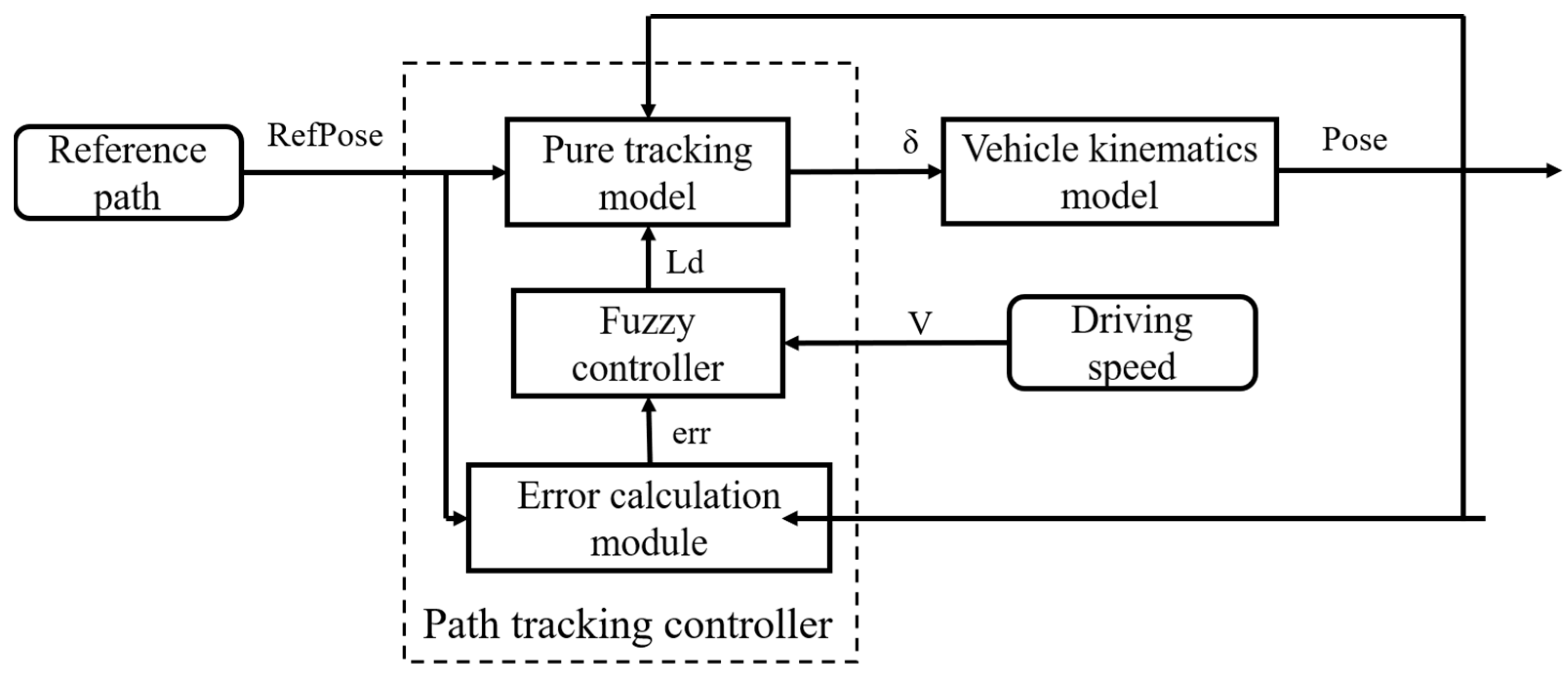
2. Path Tracing Model and Control Algorithm
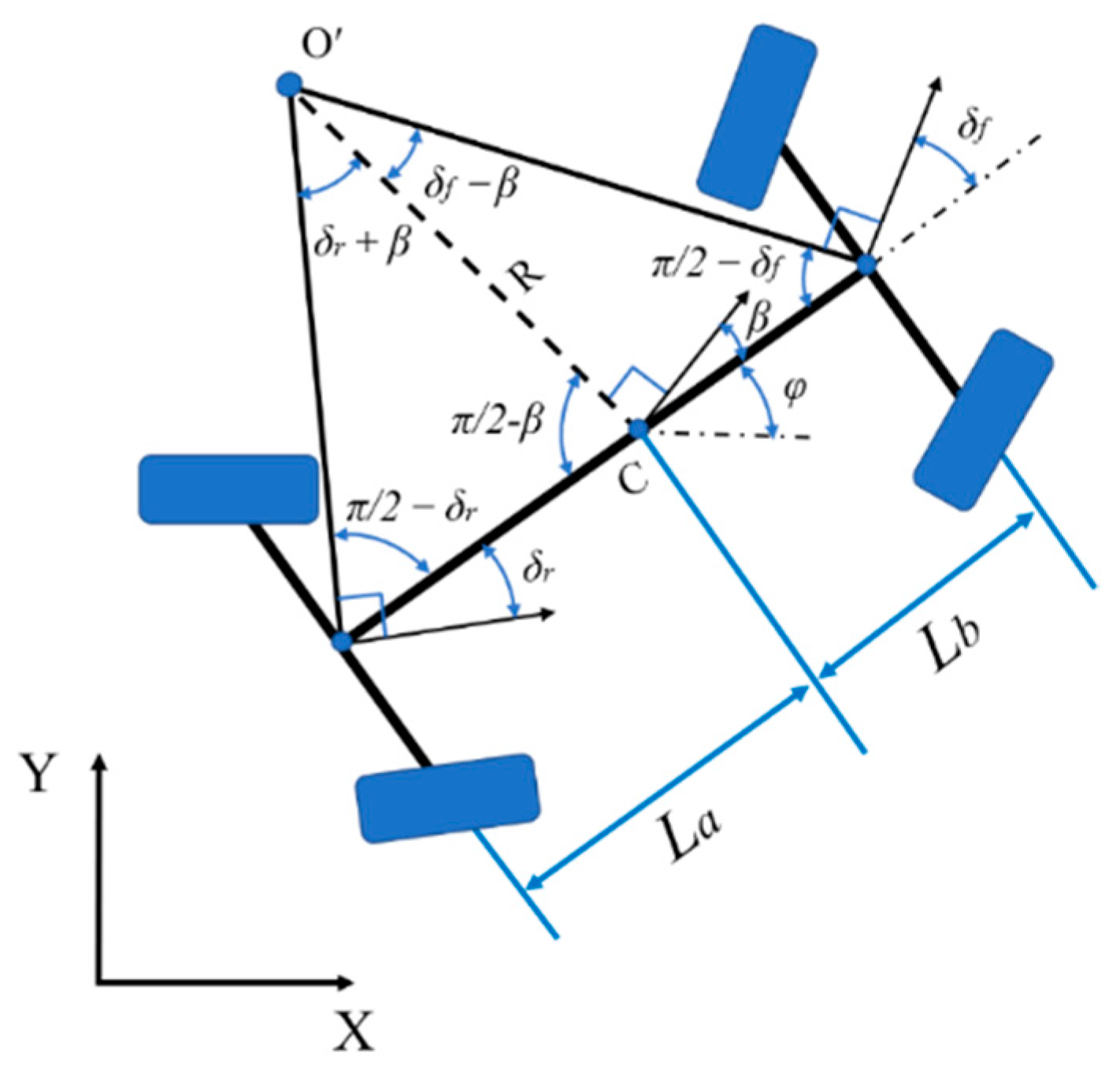
2.1. Establishment of 4WS Vehicle Kinematics Model
- Assume that the vehicle is a moving object on a two-dimensional plane;
- Assuming that the tires on both sides of the vehicle have the same speed and steering angle during driving, the left and right tires of the vehicle are regarded as one tire, and the same is true for the rear wheels;
- It is assumed that the speed of the vehicle changes slowly, and the transfer of the front and rear axle loads is ignored;
- Assume that the vehicle is a rigid body;
- It is assumed that the vehicle steering is four-wheel steering.
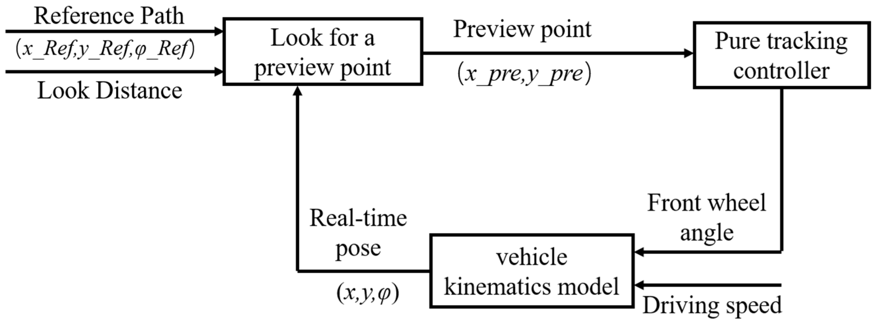
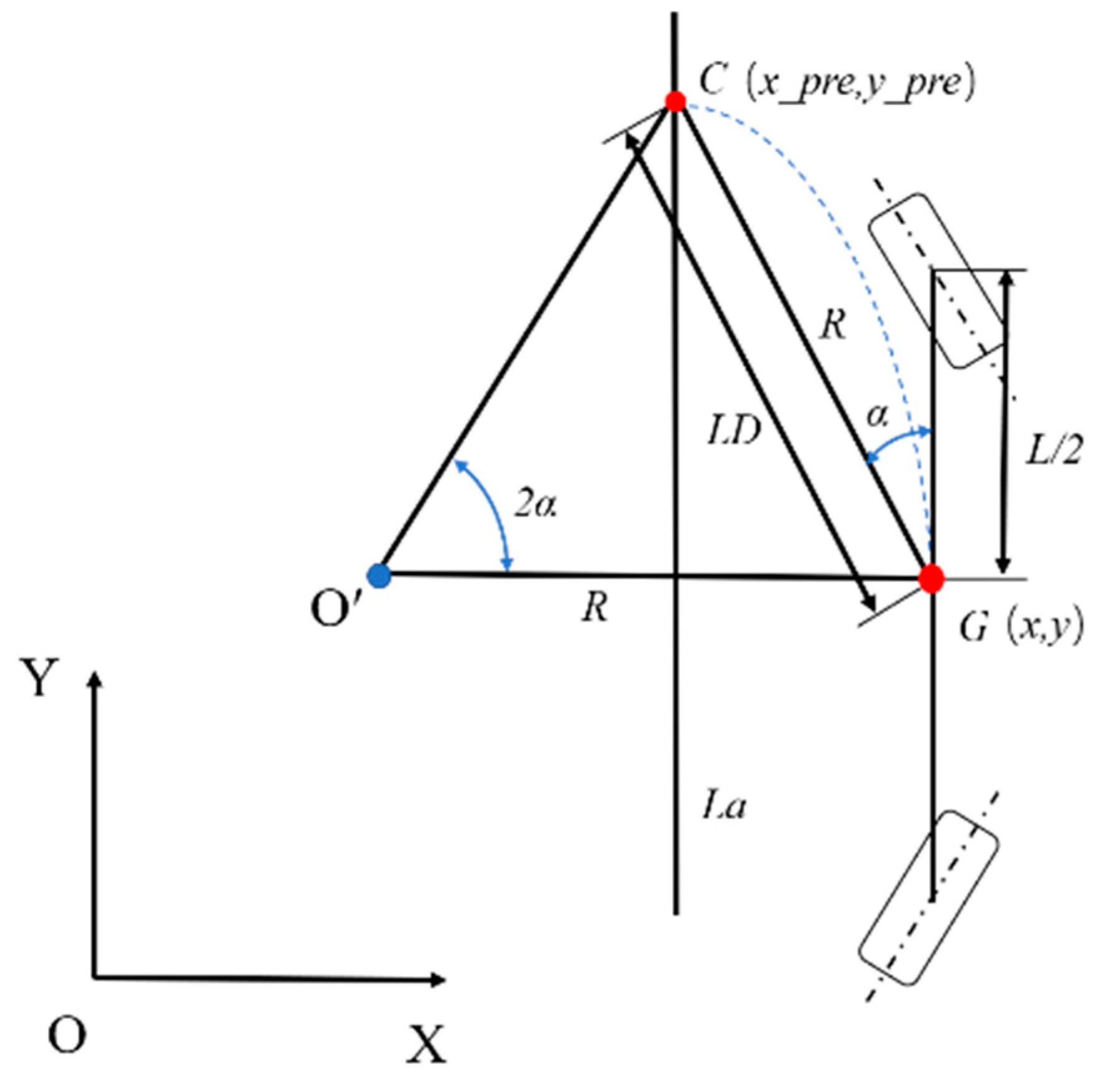
2.2. 4WS Pure Tracking Algorithm Control Principle
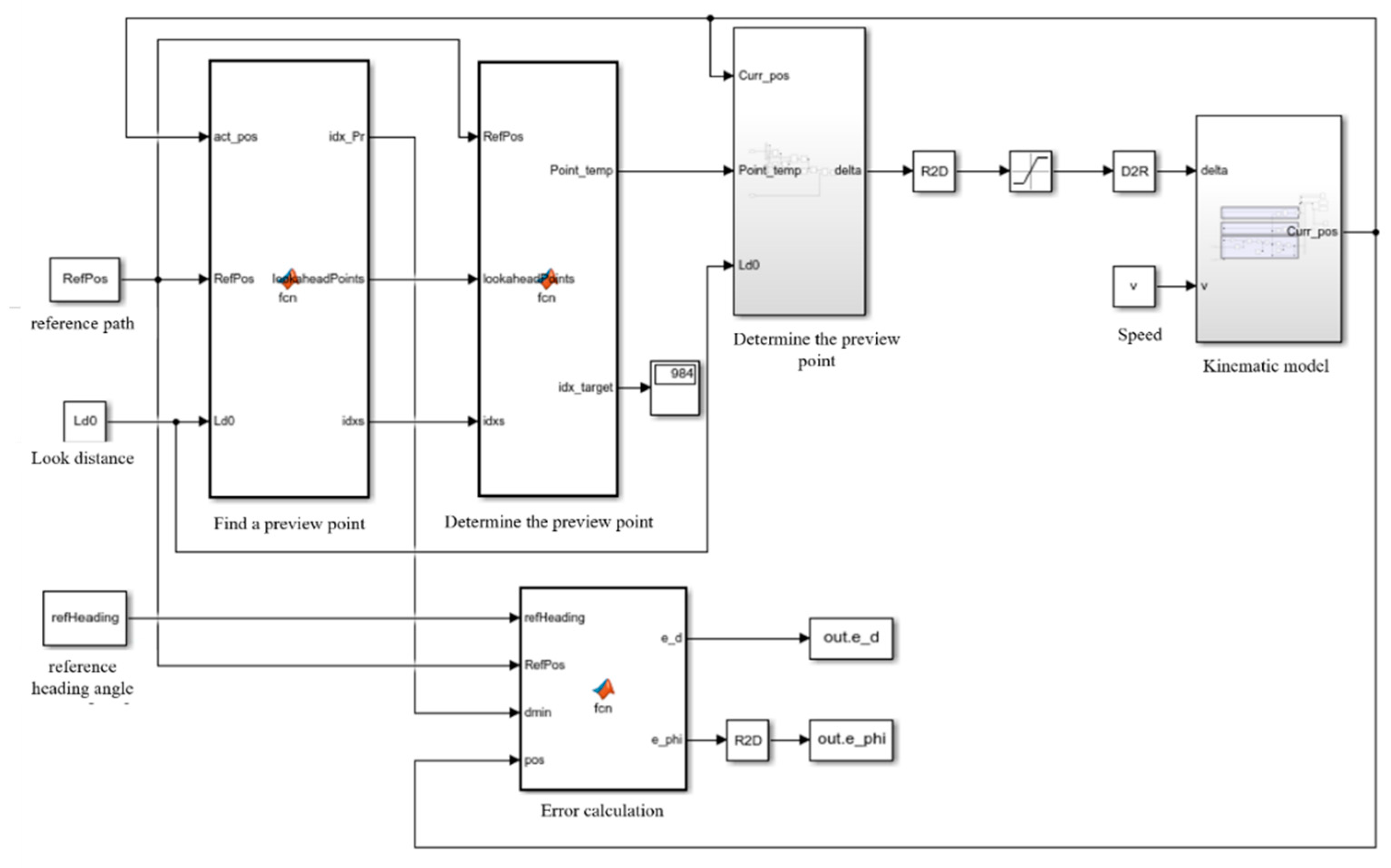
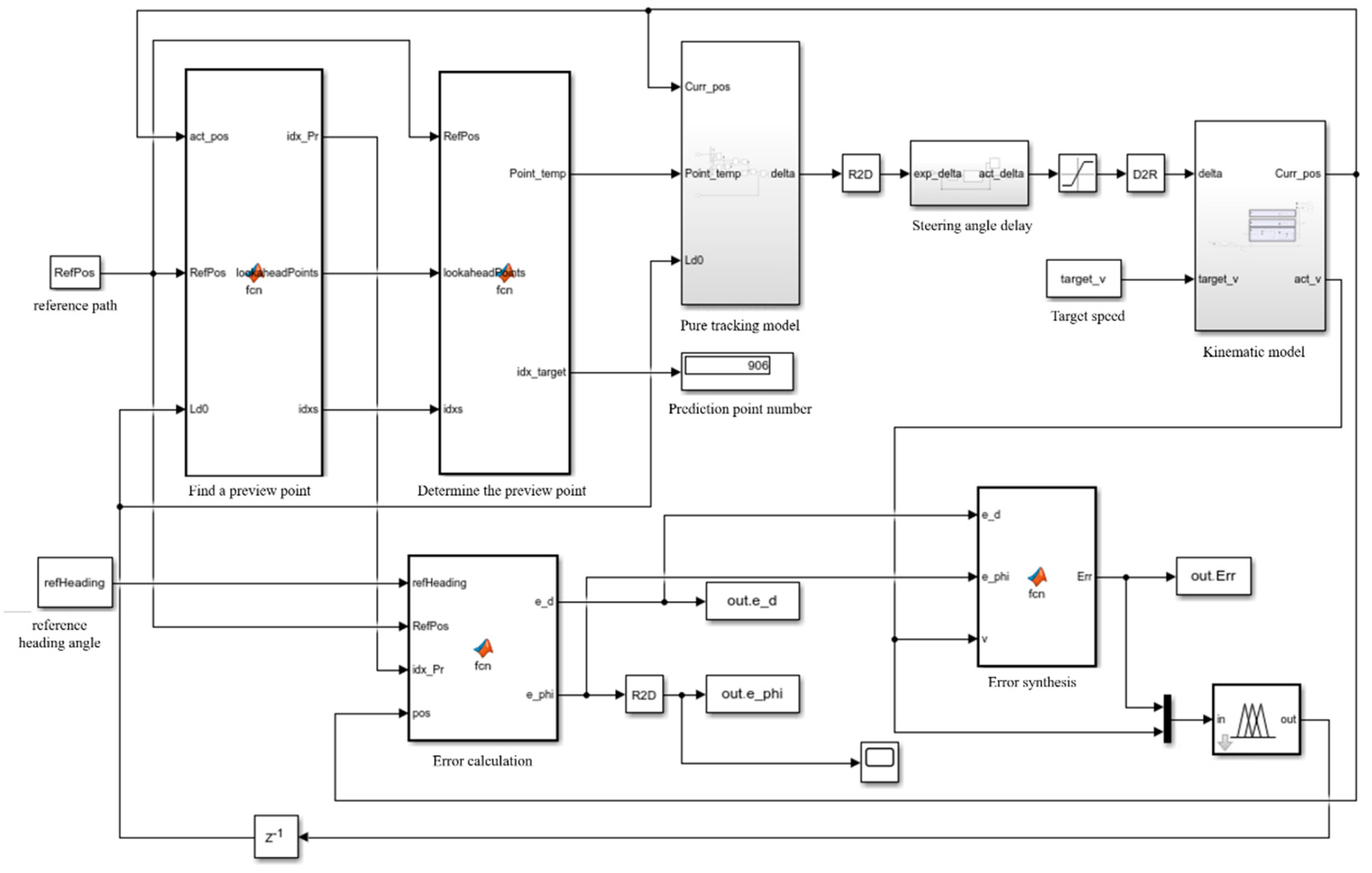
2.3. Simulation of 4WS Pure Tracking Algorithm
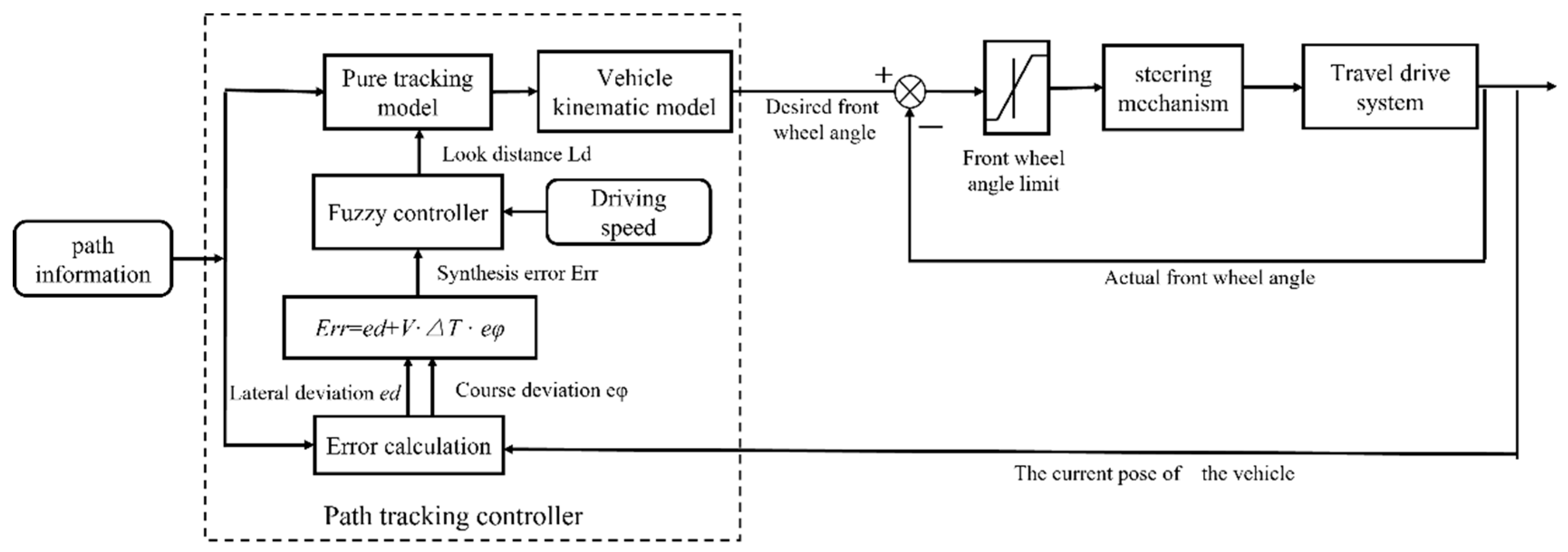
3. Improvement of Pure Tracking Algorithm Based on Fuzzy Control
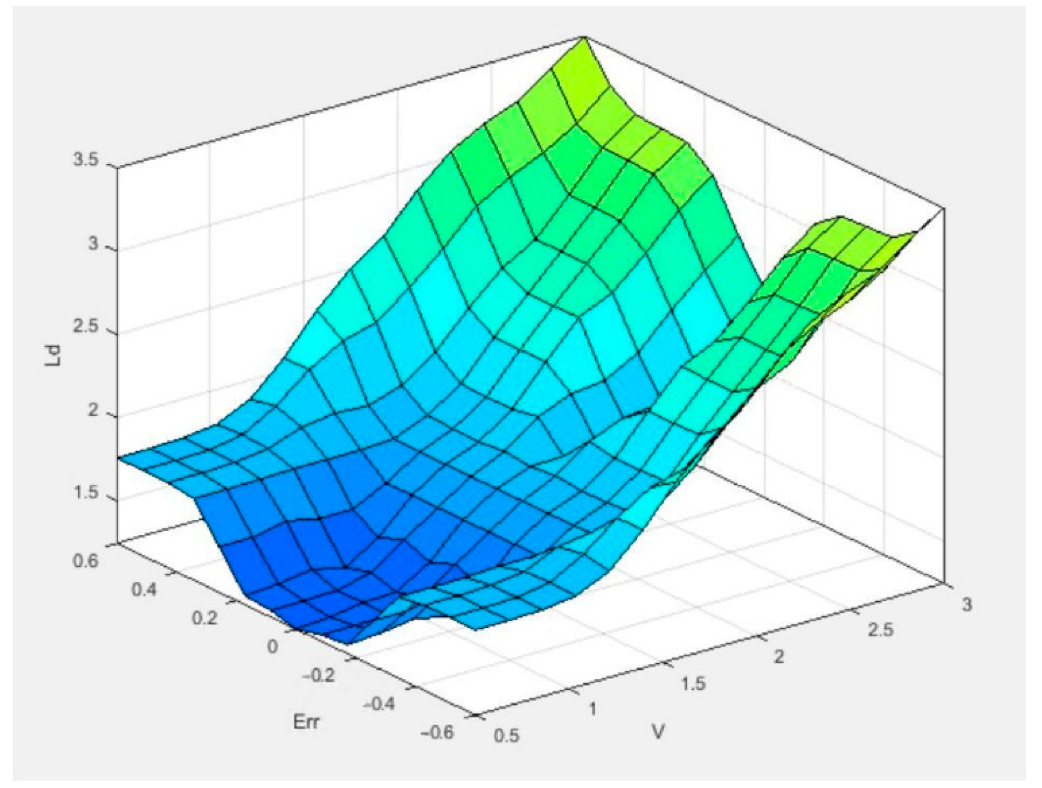
3.1. Design of Fuzzy Control Input and Output
- (1)
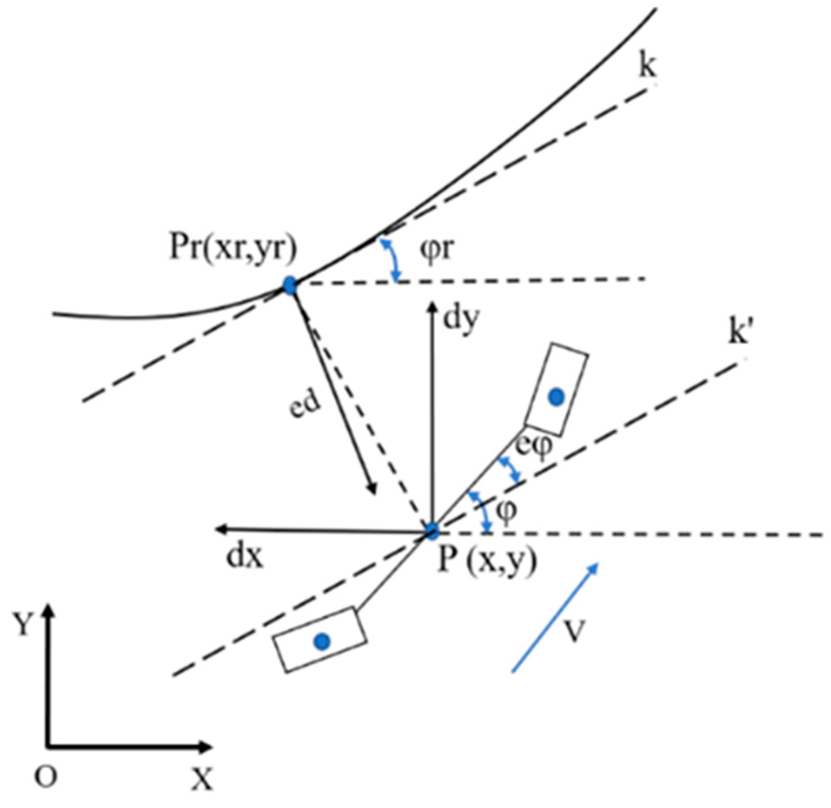
- Synthesis error
- (2)
- System universe design
3.2. Design of Fuzzy Control Rules
3.3. Simulation of Pure Tracking Algorithm for Fuzzy Control
3.4. Work Path Planning
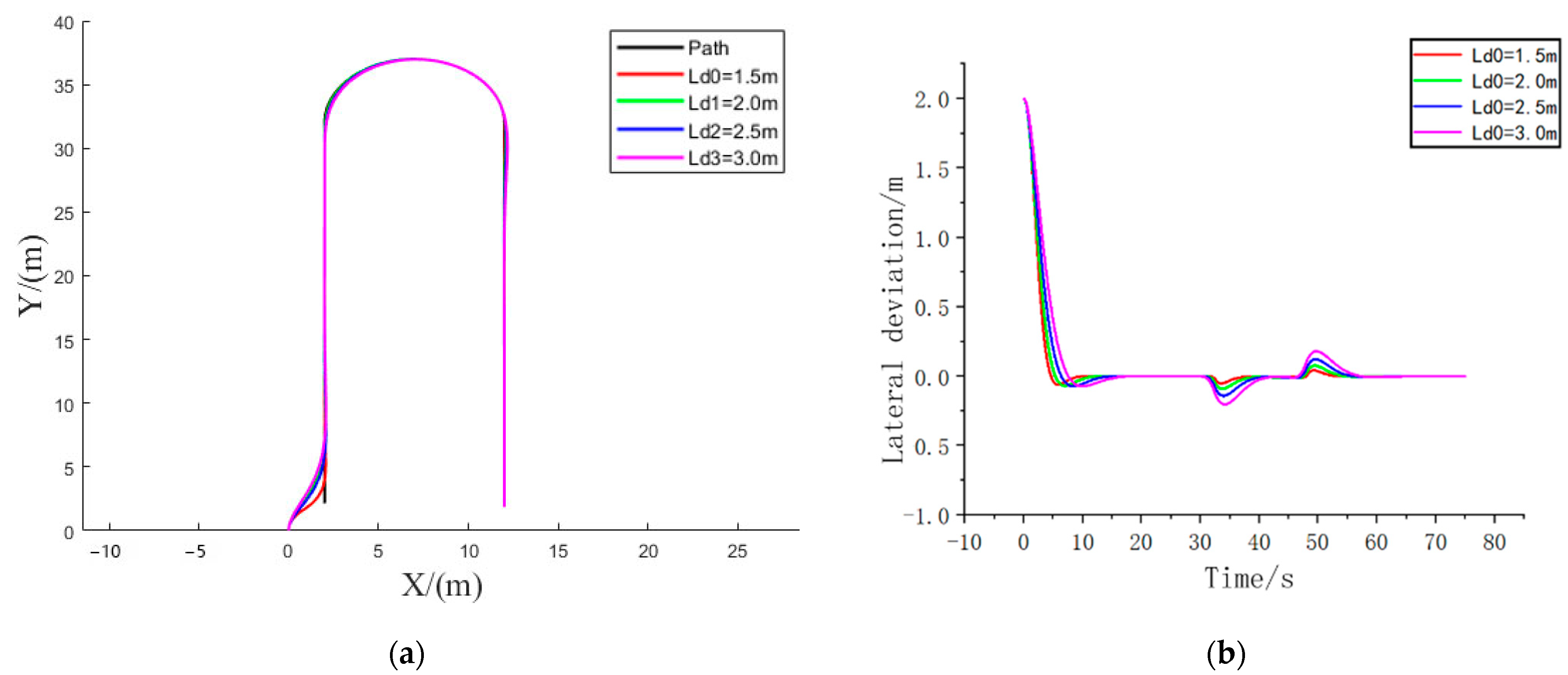
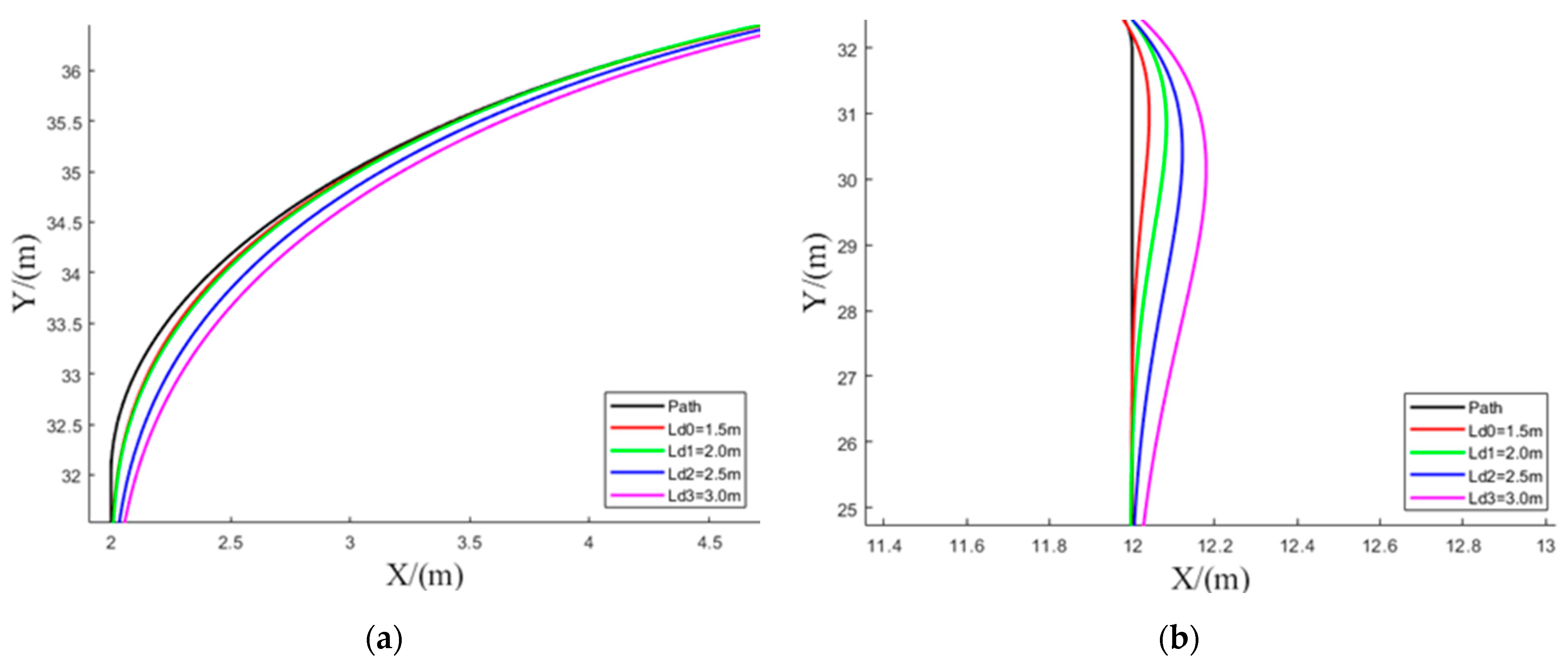
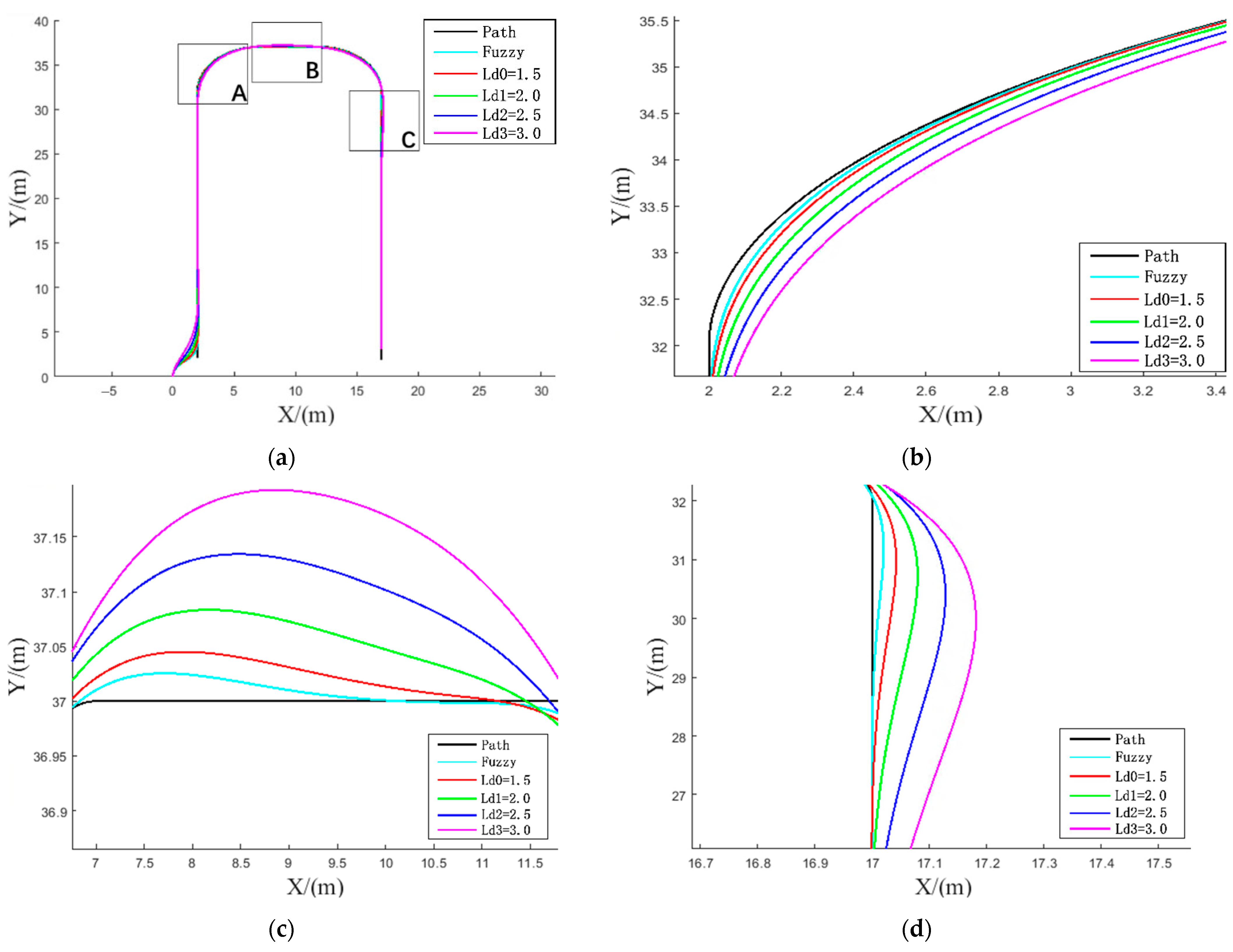
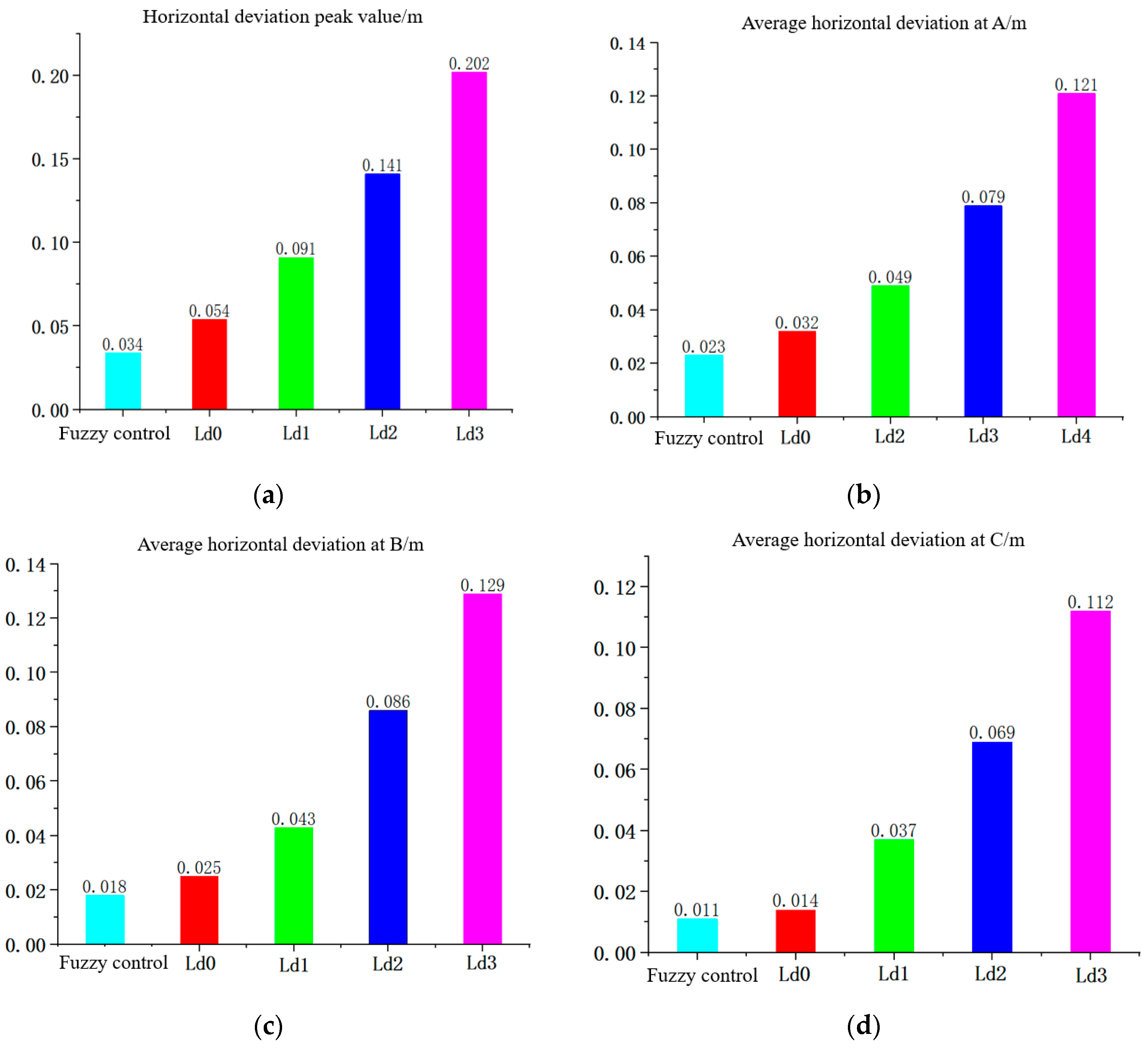
3.5. Analysis of Simulation Results
4. Real Vehicle Test and Result Analysis
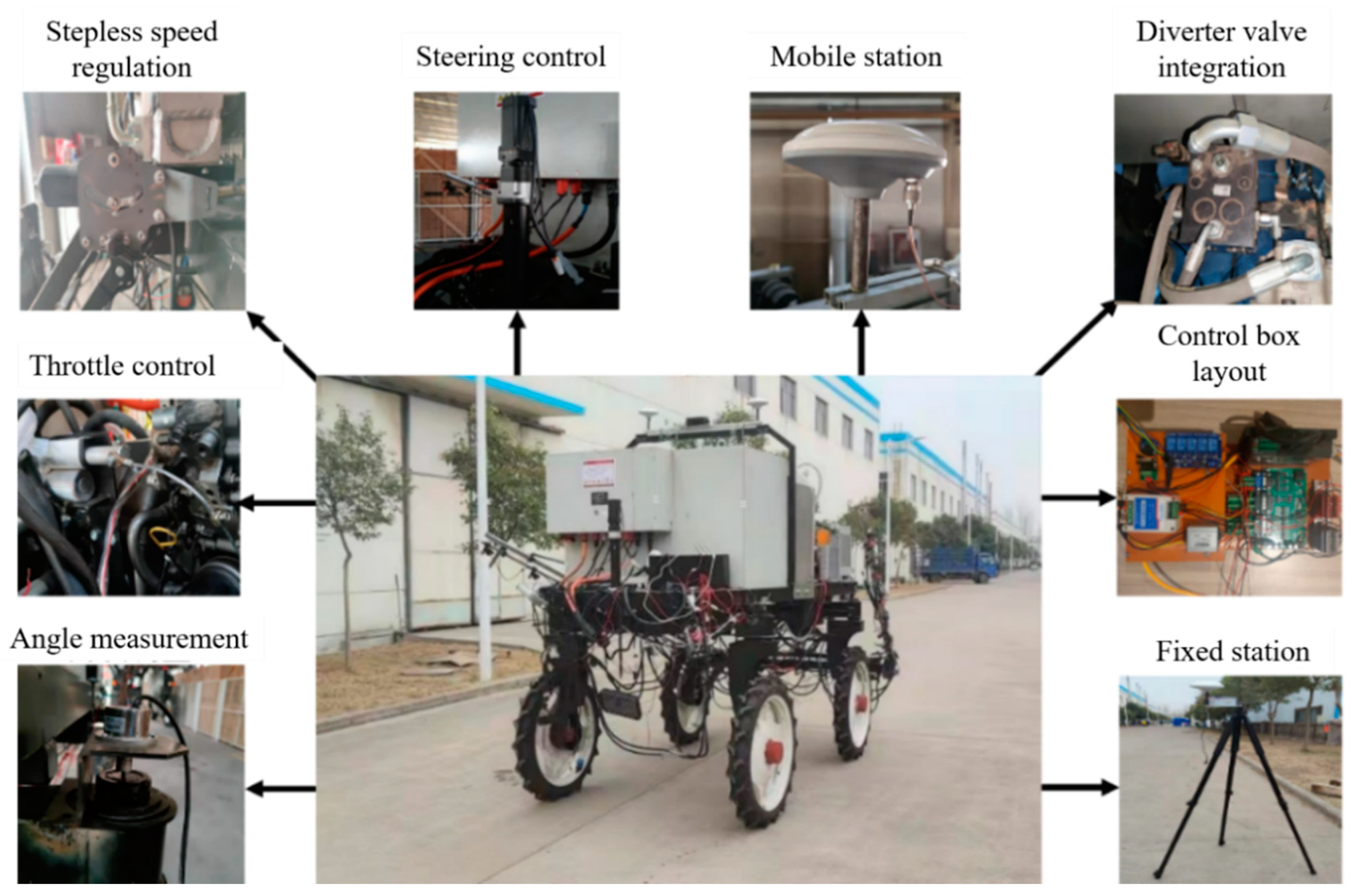
4.1. 4WS Agricultural Machinery TEST Platform
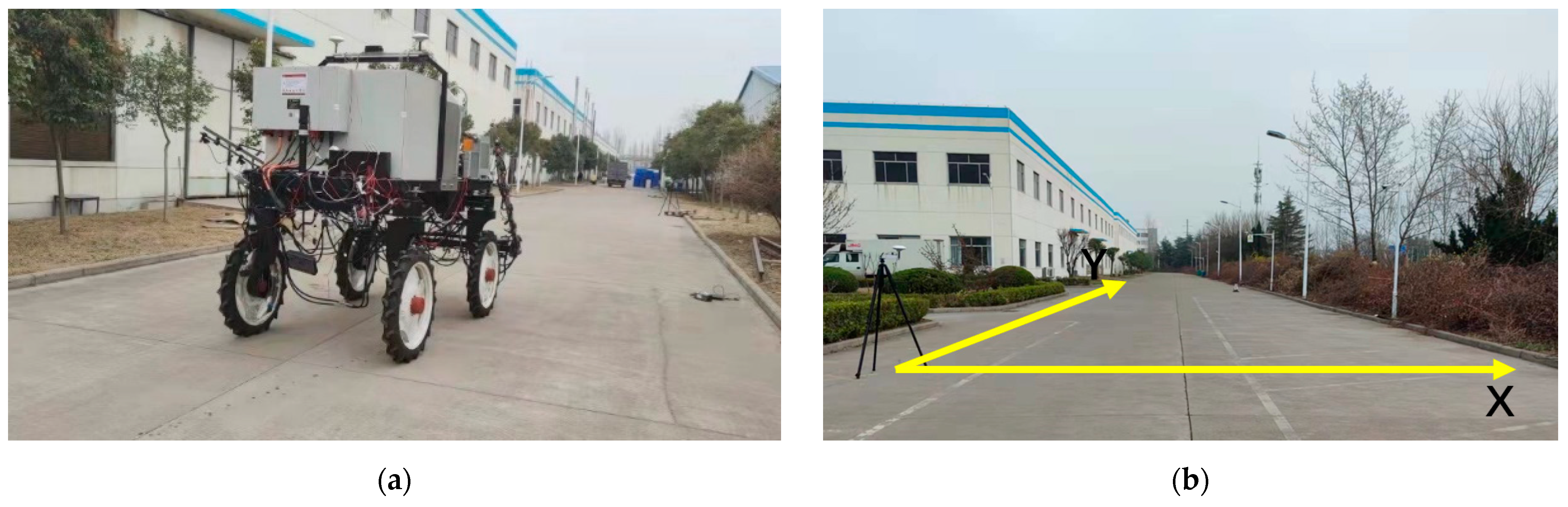
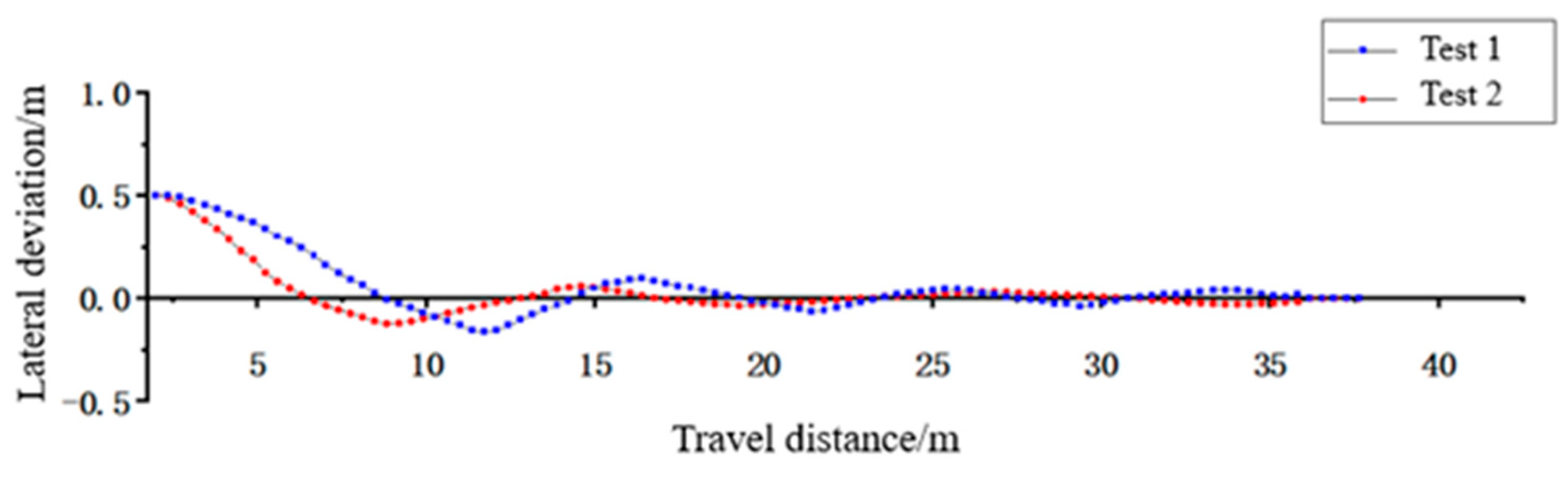
4.2. Straight Line Path Tracking Test
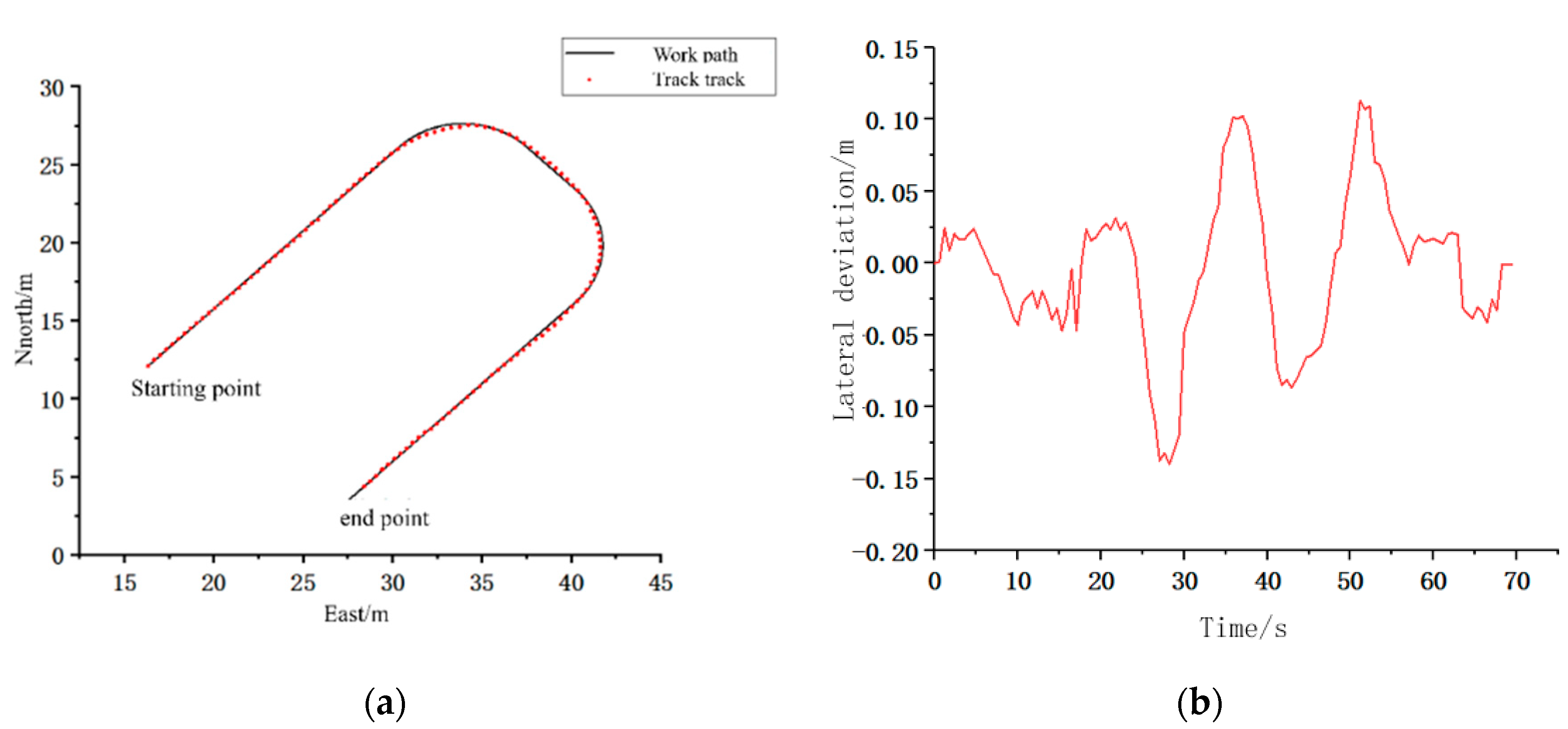
4.3. Turning Path Tracking Test
5. Discussion
- 1.
- Traditional pure tracking algorithm comparison
- 2.
- Comparison of four-wheel steering and two-wheel steering
- 3.
- Comparison with other pure tracking algorithms
6. Conclusions
Author Contributions
Funding
Institutional Review Board Statement
Informed Consent Statement
Data Availability Statement
Conflicts of Interest
References
- Luo, X.; Liao, J.; Zou, X. Information technology to enhance agricultural mechanization. J. Agric. Eng. 2016, 20, 1–14. [Google Scholar]
- Liu, Z.; Zhang, Z.; Luo, X. Design of GNSS automatic navigation operation system for Leivol ZP9500 upland gap sprayer. J. Agric. Eng. 2018, 34, 15–21. [Google Scholar]
- Li, S.; Xu, H.; Ji, Y.; Cao, R.; Zhang, M.; Han, L. Development of a following agricultural machinery automatic navigation system. Comput. Electron. Agric. 2019, 158, 335–344. [Google Scholar] [CrossRef]
- Hu, J.; Gao, L.; Bai, X. Research progress of automatic navigation technology for agricultural machinery. J. Agric. Eng. 2015, 31, 1–10. [Google Scholar]
- Ji, C.; Zhou, J. Analysis of the development of agricultural machinery navigation technology. J. Agric. Mach. 2014, 45, 44–54. [Google Scholar]
- Xie, B.; Liu, J.; He, M.; Cai, L.; Xu, Z.; Cui, B. Improved AOA model for the design of unmanned navigation parameter detection system for farm machinery in large fields. J. Agric. Eng. 2021, 37, 40–51. [Google Scholar]
- Tang, L. Research on automatic navigation technology for agricultural mechanization. Agric. Mach. Sci. Technol. Promot. 2020, 20, 18–19. [Google Scholar]
- Zhai, W.; Wang, D.; Chen, Z.; Dong, L.; Zhao, X.; Wu, C. Autonomous operation path planning method for unmanned agricultural machines. J. Agric. Eng. 2021, 37, 1–7. [Google Scholar]
- Lan, Y.; Zhao, D.; Zhang, Y.; Zhu, J. Exploration and development prospect of eco-unmanned farm model. J. Agric. Eng. 2021, 37, 312–327. [Google Scholar]
- Wang, H.; Wang, G.; Luo, X.; Zhang, Z.; Gao, Y.; He, J.; Yue, B. A pre-targeting tracking model-based path tracking control method for agricultural machine navigation. J. Agric. Eng. 2019, 35, 11–19. [Google Scholar]
- Duan, X.; Tao, J.; Qin, C.; Cai, D.; Li, Y.; Liu, C. Stable control method for path tracking of agricultural machinery under variable speed conditions. J. Agric. Mach. 2019, 50, 18–24+32. [Google Scholar]
- Bai, X.; Meng, P.; Wang, Z.; Shi, J. A navigation control method for agricultural machinery based on motion characteristics. J. Agric. Mach. 2021, 52, 21–27. [Google Scholar]
- Chai, S.; Yao, L.; Xu, L.; Chen, Q.; Xu, T.; Yang, Y. Research on path tracking of greenhouse farm machinery based on dynamic forward-looking distance pure tracking model. Chin. J. Agric. Mach. Chem. 2021, 42, 58–64+79. [Google Scholar]
- Jiang, H. Research on Automatic Navigation System of Agricultural Machinery Based on RTK Technology; Zhejiang University: Hangzhou, China, 2019. [Google Scholar]
- Bayar, G.; Bergerman, M.; Koku, A.B. Improving the trajectory tracking performance of autonomous orchard vehicles using wheel slip compensation. Biosyst. Eng. 2016, 146, 149–164. [Google Scholar] [CrossRef] [Green Version]
- Morales, J.; Martinez, J.; Mandow, A.; Garcia-Cerezo, A.J. Steering the last trailer as a virtual tractor for reversing vehicles with passive on-and off-axle hitches. IEEE Trans. Ind. Electron. 2013, 60, 5729–5736. [Google Scholar] [CrossRef]
- Lenain, R.; Thuilot, B.; Cariou, C.; Martinet, P. Adaptive and Predictive path tracking control for off-road mobile Robots. Eur. J. Control. 2007, 13, 419–439. [Google Scholar] [CrossRef]
- Backman, J.; Oksanen, T.; Visala, A. Navigation system for agricultural machines: Nonlinear model predictive path tracking. Comput. Electron. Agric. 2012, 82, 32–43. [Google Scholar] [CrossRef]
- Thrun, S.; Montemerlo, M.; Dahlkamp, H. Stanley: The robot that won the DARPA grand challenge. J. Field Robot. 2006, 23, 661–692. [Google Scholar] [CrossRef]
- Hiraoka, T.; Nishihiara, O.; Kumamo, H. Automatic path-tracking controller of a four-wheel steering vehicle. Veh. Syst. Dyn. 2009, 47, 1205–1227. [Google Scholar] [CrossRef]
- Tan, X.; Liu, D.; Xiong, H.; Yin, W.; Pan, Y. 4WS vehicle steering decoupling for dual-point tracking control. Control. Theory Appl. 2022, 3, 32–39. [Google Scholar]
- Guo, B.; Du, X.; Tao, X. Algorithm improvement based on pure tracking model. Automot. Pract. Technol. 2019, 15, 32–34. [Google Scholar]
- Kapsalis, D.; Sename, O.; Milanes, V.; Molina, M. Design and Experimental Validation of an LPV Pure Pursuit Automatic Steering Controller. IFAC-PapersOnLine 2021, 54, 63–68. [Google Scholar] [CrossRef]
- Li, T.; Hu, J.; Gao, L.; Liu, X.; Bai, X. Agricultural machine path tracking method based on fuzzy adaptive pure pursuit model. Nongye Jixie Xuebao/Trans. Chin. Soc. Agric. Mach. 2013, 44, 205–210. [Google Scholar]
- Wang, K.; Liu, Y.; Li, Y. Model-based prediction of transverse sway and lateral stability control. Beijing Automot. 2018, 4, 10–13. [Google Scholar]
- Li, Y.; Li, S.; Wu, C.; Chen, G. Pure tracking trajectory control based on hardware-in-the-loop simulation implementation. Agric. Mach. Use Maint. 2021, 4, 47–48. [Google Scholar]
- Xie, F.; Li, J.; Li, Z.; Lin, Z. Research on path planning and trajectory tracking control of orchard mowing robot. China Trop. Agric. 2021, 26, 16–24. [Google Scholar]
- Yu, L.; Yan, X.; Kuang, Z.; Chen, B.; Zhao, Y. Driverless bus path tracking based on fuzzy pure pursuit control with a front axle reference. Appl. Sci. 2019, 10, 230. [Google Scholar] [CrossRef] [Green Version]
- Ni, T.; Li, W.; Zhang, H.; Kong, Z. Pose rediction of autonomous full tracked vehicle based on 3D sensor. Sensors 2019, 19, 5120. [Google Scholar] [CrossRef] [PubMed] [Green Version]
- Wang, H.; Liu, B.; Qiao, J. Advanced High-Speed Lane Keeping System of Autonomous Vehicle with Sideslip Angle Estimation. Machines 2022, 10, 257. [Google Scholar] [CrossRef]


| Look Distance Ld | Synthesis Error Err | |||||||
|---|---|---|---|---|---|---|---|---|
| NB | NM | NS | O | PS | PM | PB | ||
| Car speed V | VS | S | S | VS | VS | VS | S | S |
| S | S | S | VS | VS | VS | S | S | |
| M | M | S | S | S | S | S | M | |
| B | B | M | M | S | M | M | B | |
| VB | VB | B | B | M | B | B | VB | |
| Main Parameters | Parameters |
|---|---|
| Drive method | Four-wheel drive |
| Steering method | Four-wheel steering |
| Dimension | 3050 mm × 1300 mm × 2000 mm |
| Quality | 2000 kg |
| Tire radius | 400 mm |
| Wheelbase | 1800 mm |
| Front Wheelbase | 1300 mm |
| Rear wheelbase | 1300 mm |
| Working speed | 3~6 Km/h |
| Maximum travel speed | 10 Km/h |
| Group | Travel Speed/(m/s) | Look Distance/(m) | Maximum Overshoot/(m) | Maximum Lateral Deviation/(m) | Steady-State Deviation/(m) | Average Deviation/(m) |
|---|---|---|---|---|---|---|
| 1 | 1.2 | 1.5 | 0.164 | 0.094 | 0.061 | 0.085 |
| 2 | Variable speed | Non-fixed | 0.123 | 0.058 | 0.039 | 0.064 |
Publisher’s Note: MDPI stays neutral with regard to jurisdictional claims in published maps and institutional affiliations. |
© 2022 by the authors. Licensee MDPI, Basel, Switzerland. This article is an open access article distributed under the terms and conditions of the Creative Commons Attribution (CC BY) license (https://creativecommons.org/licenses/by/4.0/).
Share and Cite
Zhang, C.; Gao, G.; Zhao, C.; Li, L.; Li, C.; Chen, X. Research on 4WS Agricultural Machine Path Tracking Algorithm Based on Fuzzy Control Pure Tracking Model. Machines 2022, 10, 597. https://doi.org/10.3390/machines10070597
Zhang C, Gao G, Zhao C, Li L, Li C, Chen X. Research on 4WS Agricultural Machine Path Tracking Algorithm Based on Fuzzy Control Pure Tracking Model. Machines. 2022; 10(7):597. https://doi.org/10.3390/machines10070597
Chicago/Turabian StyleZhang, Chengliang, Guanlei Gao, Chunzhao Zhao, Lei Li, Changpu Li, and Xiyuan Chen. 2022. "Research on 4WS Agricultural Machine Path Tracking Algorithm Based on Fuzzy Control Pure Tracking Model" Machines 10, no. 7: 597. https://doi.org/10.3390/machines10070597