Article

Systematic Design of a 3-DOF Dual-Segment Continuum Robot for In Situ Maintenance in Nuclear Power Plants

1
School of Mechanical Engineering and Automation, Beihang University, Beijing 100191, China
2
Nuclear Power Institute of China, Chengdu 610041, China
*
Author to whom correspondence should be addressed.
Machines 2022, 10(7), 596; https://doi.org/10.3390/machines10070596
Submission received: 23 June 2022 / Revised: 13 July 2022 / Accepted: 18 July 2022 / Published: 21 July 2022
(This article belongs to the Section Electromechanical Energy Conversion Systems)

Abstract

:
In situ maintenance works for nuclear power plants are highly beneficial as they can significantly reduce the current maintenance cycle and cost. However, removing absorber balls in a constrained environment through an inspection port is fairly challenging. In this article, a 3-DOF dual-segment continuum robot system is proposed which is equipped with an end-effector to remove absorber balls by pneumatic conveying. Then, according to the symmetrical layout of actuation ropes, the kinematics of the single-segment continuum robot are extended, and the kinematics equation which is universal to the continuum robot with the dual segment is summarized. In addition, some special kinematics solutions can be obtained according to opposite-bending and feeding characteristics. Finally, the functions of the device are verified by tests. The results show that the continuum robot can smoothly pass through the divider plug and reach any position at the bottom of a ball-storage tank where absorber balls are located with only two segments. In a gas environment, the efficiency of absorber ball removal can reach 58.96 kg/h with a lift of 7.5 m and 48.54 kg/h with a lift of 10 m. This result undoubtedly paves the way for the in-service maintenance of nuclear power plants.

1. Introduction

To ensure the safe operation of a nuclear power plant, it must be equipped with two sets of independent reactivity control systems with different principles [1,2]. The absorber ball shutdown system is the second shutdown system of a high-temperature gas-cooled reactor (HTR) which is used for the emergency shutdown of the HTR when the control rod emergency shutdown system (the first shutdown system) fails [3,4]. Generally speaking, when the absorber ball in the shutdown system reaches the end of service life, it is necessary to disassemble the absorber ball shutdown system to replace the ineffective absorber balls for it to run normally again, which takes a lot of time and money. Therefore, it is of great significance to use the existing detachable inspection port for in situ maintenance in service.
Considering the radioactive hazards of the nuclear environment, remote robotic manipulators have always been the first choice for performing tasks in nuclear environments [5,6,7]. Nuclear operations in open areas are usually carried out by conventional serial robots [8], but they are too big to function in confined spaces. Continuum robots, which can also be controlled remotely, are the best choice [9,10,11]. By virtue of its high length-to-diameter ratio, the continuum robot can pass through the inspection port and bypass obstacles to enter the reactor, inspect the internal components, and retract along its entry path without disturbing the environment. These characteristics are also an important guarantee for in situ maintenance of nuclear power plants in service. The origin of the continuum robot can be traced back to 1999, when the researchers Robinson and Davies [12] used the term “continuum manipulator” for the first time, which is equivalent to the “continuous morphology manipulator” defined by Chirikjian [13]. In the past 30 years, the continuum robot, expect for in the nuclear industry [14], has been widely used in aviation maintenance [15,16], medical surgery [17,18,19,20], space [21], oceans [22], and other fields [23], especially in aviation maintenance [24] and minimally invasive surgery [25,26].
Many research institutions have designed a variety of continuum robots to be used in nuclear reactors [27,28,29,30] (see Appendix A for details). Qin, G. et al. developed a remote operating system with a continuum robot as the main body and conducted simulation experiments to verify the feasibility of working in a narrow vacuum chamber [9]. Keogh K. et al. designed a continuum robot system with end-effectors for laser cutting and welding for in bore use in EU-DEMO service pipes [10]. However, most of these studies remain in the laboratory and practical applications in nuclear environments are still rare. Among them, the continuum robots of OC Robotics have been successfully applied in the maintenance of nuclear reactors [31], such as pipeline maintenance of the Ringhals 1 nuclear power plant in 2003 and feed pipe inspection of the deuterium uranium reactor in Canada in 2010. They have also been deployed in other applications for largely noncontact operations in narrow and constrained spaces, such as the interiors of airframes [32].
Starting from the actual engineering requirements, in order to solve the problem of removing absorber balls from absorber ball shutdown systems, a 3-DOF dual-segment continuum robot system has been designed. The distal end of the robot is equipped with an end-effector to remove the absorber ball in the ball-storage tank by pneumatic conveying. In addition, in order to ensure that the continuum robot can reach any position at the bottom of the tank where the absorber balls are located and remove as many absorber balls as possible, a universal kinematics equation for the dual-segment continuum robot was obtained based on the kinematics of the single-segment continuum robot, and the relationship between the length of actuation ropes and the spatial pose of the continuum robot was clarified. On this basis, the workspace of the two-segment continuum robot around the ball-falling column in the ball-storage tank was simulated. Finally, a series of validation tests were carried out to check the key features of the prototype.

2. Mechanism Design

2.1. Design Requirements of the Continuum Robot

The inspection port is shown in Figure 1(a.ii), which is also the port through which absorber balls are injected into the ball-storage tank, for which reason it is called the ball-falling column. The ball-falling column is a hollow slender column (length: 2600 mm); the narrowest diameter of the inner hole is only 50 mm, and a rectangular notch is opened in the middle (see Figure 1(a.iii)). Therefore, the removal operation requires the device to enter the ball-falling column through the inspection port first and then enter the ball-storage tank through the divider plug (see Figure 1(a.iv)), which requires the device to have a high length–diameter ratio and high flexibility. Moreover, in the initial study, it was found that the removal performance of the steerable catheter could not meet the engineering requirements. These requirements provide a good platform for the application of continuum robots in the nuclear industry.
In this article, a novel in situ inspection and repair technology for HTRs is proposed. In its practical application, the working scene is shown in Figure 1(a.i). The specific workflow (i–vi) is shown in Figure 1b. In addition to the removal operation, the end-effector shall also have a video function to monitor the removal process.

2.2. Design of the Dual-Segment Continuum Robot

According to the design requirements and considering the comprehensive working performance of the continuum robot, a dual-segment continuum robot with rolling joints in series is proposed, as shown in Figure 2a. The parameters of the continuum robot are shown in Table 1. The arm body of the continuum robot is divided into the movable part and the supporting part. The movable part, which is divided into two segments—the proximal segment and the distal segment—provides two degrees of freedom. The supporting part is composed of two identical, straight, hollow columns in series, which are used to carry the movable part of the continuum robot through the divider plug. This is only used for feeding, not for bending motions.
As is shown in Figure 2(b.i), the movable part of the continuum robot is composed of 60 identical rolling joints. Its basic configuration is obtained by cutting a cylinder from two circles ( R = 25   mm ) on the mutually perpendicular datum plane (see Figure 2(b.ii)). When the joint bends at half of the limit angle, the bending angle can reach 54° (see Figure 2(b.iii)) to ensure that the end arm of the continuum robot has an angle sufficient for it to pass through the divider plug. In addition, the joint is a hollow structure for the laying of the ball-sucking tube and lines.
The structure of the end-effector is shown in Figure 2c. It integrates the endoscope, the collision detection device, and the ball-sucking tube. In the collision detection device, the contact sensing plate and the micro-contact switch are coupled by flexible springs. When the end-effector touches the divider plug or absorber balls, the contact sensing plate is forced to compress the spring and then trigger the micro-contact switch to realize the collision detection, which guarantees the automated removal operation. The micro-contact switch and the flexible spring are evenly distributed on the circumference of the rolling joint in a staggered manner of 120°. The endoscope integrated into the end-effector can image in real time to monitor the ball-sucking process. In addition, the outer part of the arm body is covered with a woven net that serves as a “skin” (see Figure 2c) to ensure that the outer surface is smooth and can freely enter and exit at the divider plug.

3. Kinematic Analysis of the Dual-Segment Continuum Robot

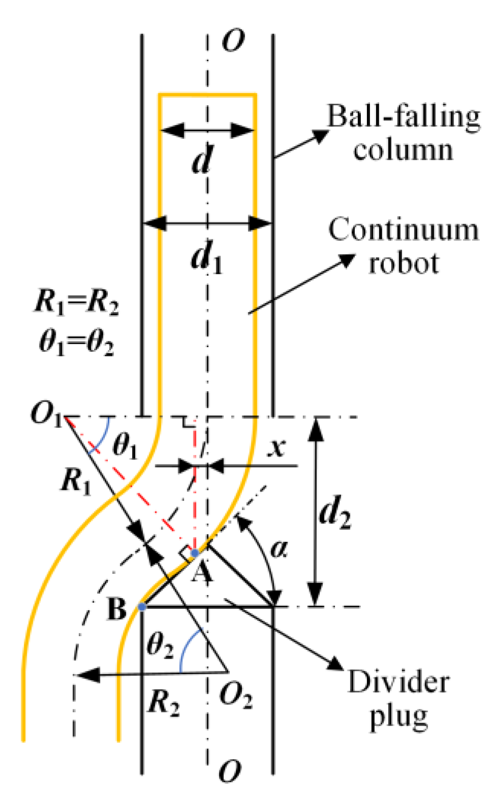
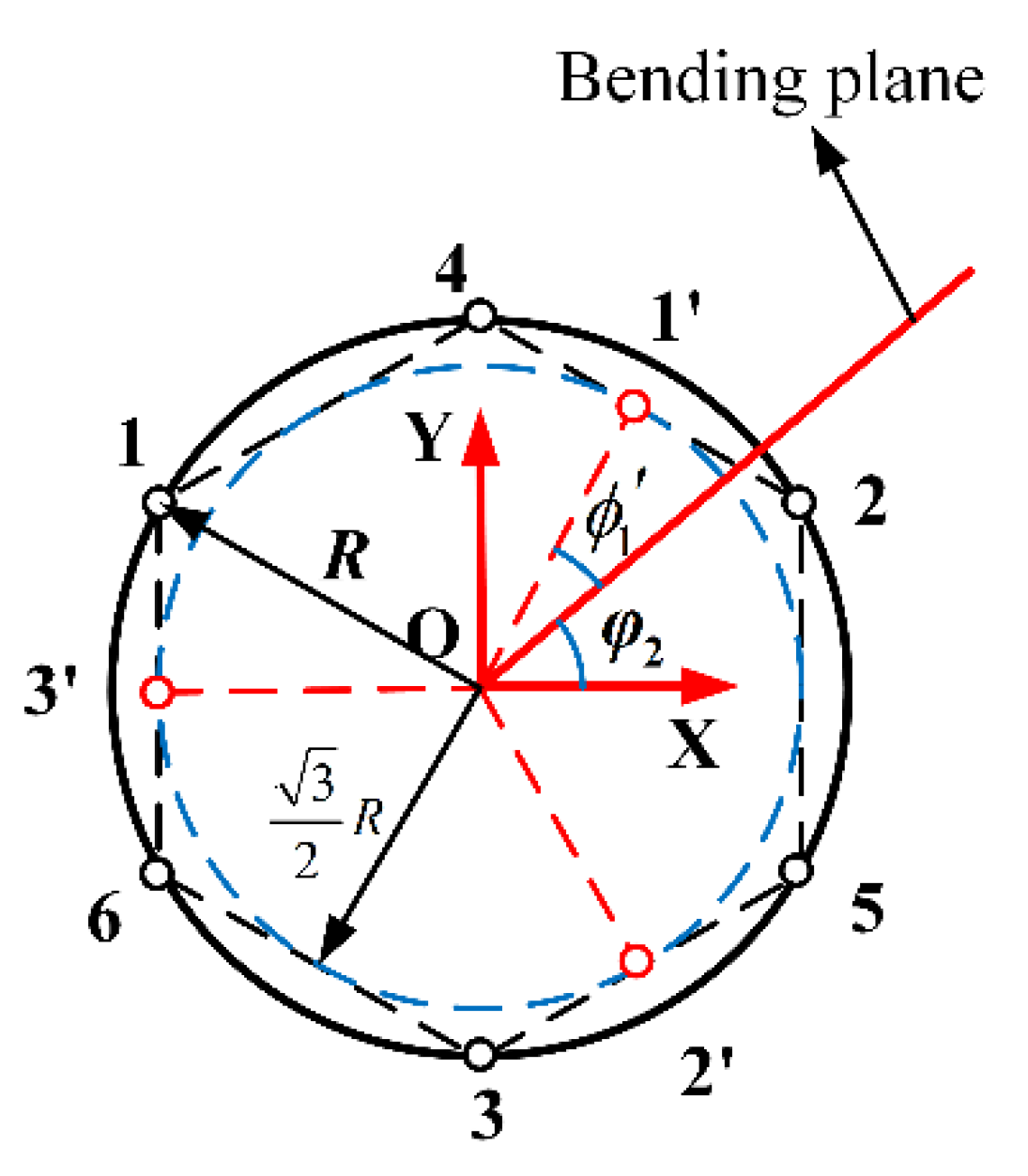
3.1. Passive Flexible Deformation

When the continuum robot passes through the divider plug, only the end arm needs to actively bend at a certain angle (θ1, θ2). Due to its hyper-redundant characteristics, the residual arm can pass through the divider plug in the passive flexible deformation pose without active bending, as shown in Figure 3. In contrast, the rigid continuum robot needs to control each rigid joint separately when passing through the divider plug, so such robots are usually bulky, complicated, and costly.
When the continuum robot moves down at the divider plug, it presents opposite-bending (equal curvature) and feeding characteristics. In this case, the end-effector is always vertically down, and the two segments of the continuum robot are bent in the same plane, so the bending angles of the arms on both sides of the divider plug must be equal, i.e., θ 1 = θ 2 . Additionally, assume that the bending radius R 1 = R 2 .
So, the formula of the bending radius can be expressed as:
R 1 = [ d 2 ( d 1 2 tan α x ) ] tan α + x
In the geometric relationship shown in Figure 3, the value of x is proportional to the bending radius of the arm. When x = 0, the arm body and the divider plug form the tangent at the tip (point A) of the divider plug and the bending radius is the smallest. The mapping relationship can be expressed as:
R 1 min = lim x 0 R 1 = ( d 2 d 1 2 tan α ) tan α
The angle θ1 at which the arm needs to actively bend can be calculated as:
θ 1 = d 1 4 cos α R 1 + ( π 2 α )

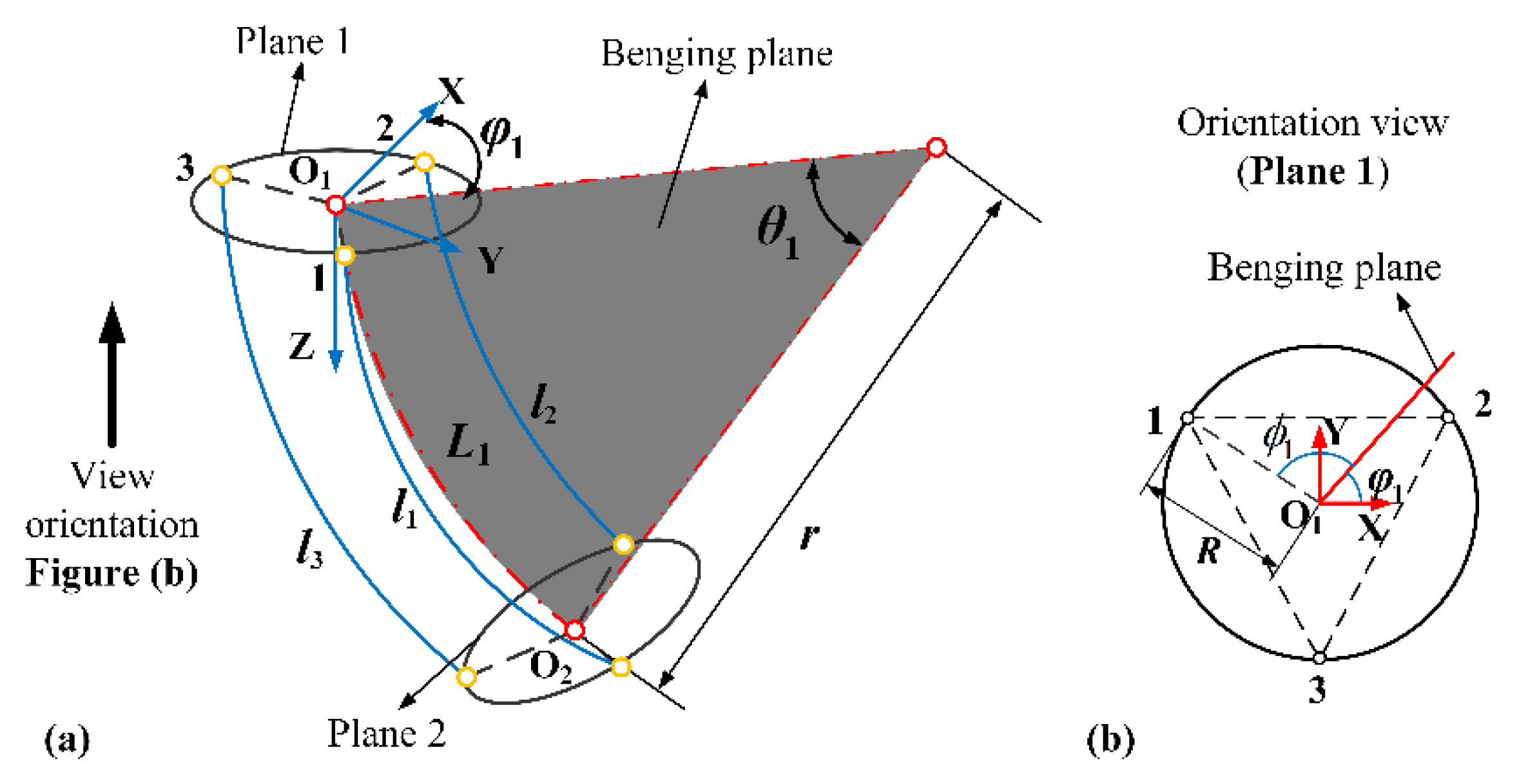
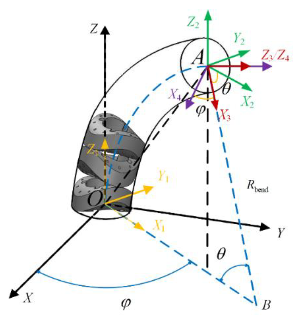
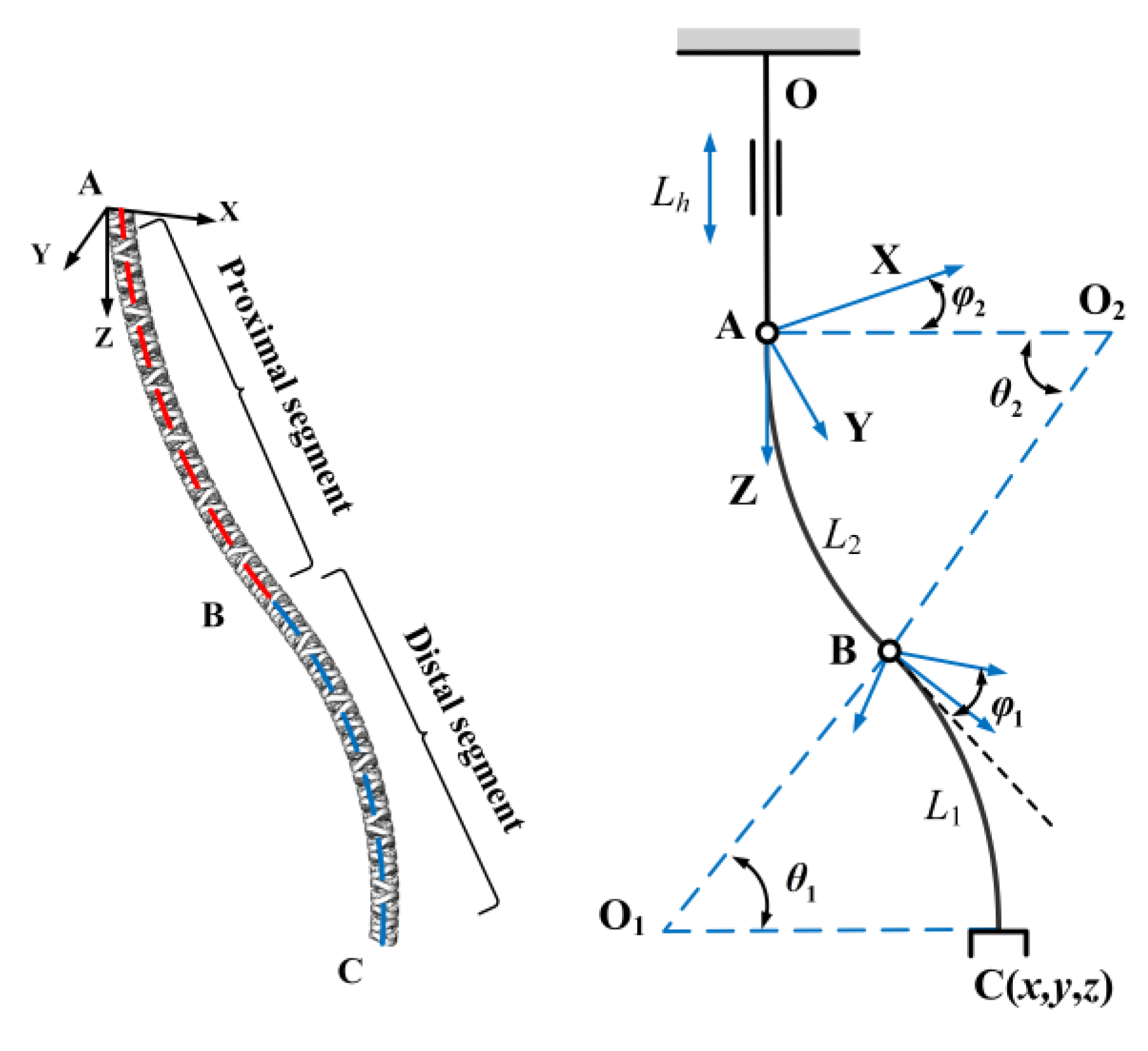
3.2. Forward Kinematics

Firstly, the mapping relationship between the cable length l i ( i = 1 , 2 , 3 ) of the distal segment and the joint space ( θ 1 , φ 1 ) is analyzed. The distal segment is driven by three actuation cables, with its own length of L 1 , as shown in Figure 4a. The positional layout of the actuation cables in the coordinate system is shown in Figure 4b. Furthermore, it is assumed that the angle between the points at which the cables are located and the bending plane is ϕ i .
This can be obtained from the geometric relationship shown in Figure 4.
l i = L 1 θ 1 R cos ϕ i
{ r 1 r 2 = R ( cos ϕ 1 cos ϕ 2 ) r 3 r 2 = R ( cos ϕ 3 cos ϕ 2 ) r 3 r 1 = R ( cos ϕ 3 cos ϕ 1 )
Substituting i = 1 , 2 , 3 into Equation (4), respectively, by setting up the equations in parallel and eliminating the parameter ϕ , the length of distal segment L 1 can be expressed as:
L 1 = l 1 + l 2 + l 3 3
In addition, the positional relationship between the actuation cable hole and the bending plane is as follows:
{ ϕ 1 = 5 π / 6 φ 1 ϕ 2 = φ 1 π / 6 ϕ 3 = π / 2 + φ 1
Combining Equations (5) and (7), the direction angle φ 1 can be obtained:
φ 1 = tan 1 ( ( l 1 + l 2 2 l 3 ) 3 ( l 1 l 2 ) )
According to the proportional relationship, there are:
r = L 1 θ 1
By combining Equations (4) and (9) above, the following can be obtained:
r = L 1 R cos ϕ i L 1 l i
Substituting i = 1   or   2   or   3 into Equation (10), then:
r = ( l 1 + l 2 + l 3 ) R sin φ 1 2 l 3 l 1 l 2
where
sin φ 1 = y y 2 + x 2 = tan φ 1 tan 2 φ 1 + 1
Substituting Equations (8) and (12) into Equation (11), the following can be obtained:
r = 3 R L 1 2 l sqrt
Further, the bending angle θ 1 of the distal segment can be expressed as:
θ 1 = 2 l s q r t 3 R
where
l sqrt = l 1 2 + l 2 2 + l 3 2 l 1 l 2 l 2 l 3 l 1 l 3
Next, the mapping relationship between the cable length l i ( i = 4 , 5 , 6 ) of the proximal segment and the joint space ( θ 2 , φ 2 ) is solved. Since the proximal segment of the continuum robot is driven by three actuation cables and another three coupled cables, which is equivalent to a total of six actuation cables, the above method cannot simultaneously use the length of six actuation cables to represent the configuration parameters of the continuum robot. However, due to the symmetry in the position of the actuation cables, the configuration can be simplified: replace two adjacent cables with one cable, as shown in Figure 5. In the mapping of the driving space to the joint space, the effect is the same before and after simplification.
According to the geometric relationship shown in Figure 5, the following can be obtained:
{ l 1 = ( l 2 + l 4 ) / 2 l 2 = ( l 1 + l 6 ) / 2 l 3 = ( l 3 + l 5 ) / 2
{ ϕ 1 = π / 3 φ 2 ϕ 2 = φ 2 + π / 3 ϕ 3 = π φ 2
The equivalent simplified three cables are located above a circle whose radius can be defined as the equivalent radius R .
R = 3 2 R
Similar to the previous method, the length of the proximal segment L 2 of the continuum robot is:
L 2 = l 1 + l 2 + l 3 + l 4 + l 5 + l 6 6
In the same way, the direction angle φ 2 of the proximal segment can be obtained.
φ 2 = tan 1 ( 3 ( l 1 l 2 ) 2 l 3 l 1 l 2 ) = tan 1 ( 3 ( l 2 + l 4 l 1 l 6 ) 2 l 3 + 2 l 5 l 1 l 2 l 4 l 6 )
Similarly, by substituting i = 1   or   2   or   3 and Equation (19) into Equation (10), the bending radius r of the proximal segment can be obtained.
r = 3 R L 2 2 l sqrt
Therefore, the bending angle θ 2 of the proximal segment is:
θ 2 = 2 l s q r t 3 R
where
l sqrt = l 1 2 + l 2 2 + l 3 2 l 1 l 2 l 2 l 3 l 1 l 3
In this section, the kinematics of the continuum robot is analyzed based on the piecewise constant curvature theory. Based on this, when the single segment continuum robot bends and deforms, the bending angle of each joint is equal and the bending direction is the same. The pose transformation is shown in Figure 6: firstly, the bending segment rotates around the z-axis with φ; secondly, the arm translates along the x-axis with L i ( 1 cos θ i ) / θ i , along the z-axis with L i sin θ i / θ i , and rotates around the y-axis with θ. Furthermore, we need to post-multiply the homogeneous matrix with the rotation matrix R z ( φ ) . The homogeneous transformation matrix T i 1 i can be expressed as:
T i 1 i ( θ i , φ i , L i ) = [ R z ( φ i ) 0 0 1 ] [ R y ( θ i ) P 0 1 ] [ R z ( φ i ) 0 0 1 ]
Accordingly, the homogeneous transformation matrix P 0 n of the whole continuum robot can be expressed as:
P 0 n = ( i = 1 n T i 1 i ) P 0
where P 0 is the homogeneous coordinate of the end point of the continuum robot in the initial state (assuming that the vertical state of the continuum robot is its initial state, θ i = 0 ).
In particular, when θ = θ 1 = θ 2 (i.e., i = 2), according to the opposite-bending and feeding characteristics of the continuum robot:
φ 1 = φ 2 + π
The terminal coordinates of the continuum robot can be expressed as:
{ x = ( L 1 + L 2 ) cos φ 2 ( 1 cos θ ) θ y = ( L 1 + L 2 ) sin φ 2 ( 1 cos θ ) θ z = ( L 1 + L 2 ) sin θ θ

3.3. Inverse Kinematics

In inverse kinematics, it is necessary to solve the drive cable lengths { l 1 , l 2 , l 3 , l 4 , l 5 , l 6 } from the given end-effector coordinates X R 6 , where the transformation is from the task space to the drive space. As shown in Figure 7, in the absorber ball removal operation, the continuum robot needs to move down first (OA section), then pass through the divider plug (point A) and enter the tank (AC section), and its end-effector remains vertical and downward during operation. Assume that the desired end position and orientation of the continuum robot is X and that the difference between the desired and the actual position and orientation is d X . According to the mapping between the joint space and the operating space, namely, the Jacobian matrix J, there is:
X · = J ( q ) q · = J ( θ , φ ) [ θ 1 · φ 1 · θ 2 · φ 2 · ] T
where θ i , η i are the bending angle and the bending direction of each segment, respectively.
The partial derivatives of X to each element of q make up the Jacobian matrix from the configuration space to the workspace.
J i , j ( q ) = X i q j , i = 1 , 2 6 ; j = 1 , 2 , 3 , 4
Consulting the linear equation theory, the inverse kinematics can be written as:
q · = J + ( q ) X · + ( I J ( q ) J + ( q ) ) w
where J + ( q ) is the generalized inverse matrix of J ( q ) , ( I J ( q ) J + ( q ) ) w is the projection w of on the null space of J + ( q ) , which is an additional item caused by the redundant degree of freedom of the continuum robot, allowing the continuum robot to reach the same point in several poses. If w = 0 , a minimal norm solution of q · can be obtained. According to Equation (28):
d q = J + ( q ) d X
According to Equation (4), the equations of actuation cable length l i can be obtained:
{ l 1 = i = 1 2 [ L i θ i R cos ( 5 π / 6 φ i ) ] = L 1 θ R cos ( 5 π / 6 φ 1 ) + L 2 θ R cos ( 5 π / 6 φ 2 ) l 2 = i = 1 2 [ L i θ i R cos ( φ i π / 6 ) ] = L 1 θ R cos ( φ 1 π / 6 ) + L 2 θ R cos ( φ 2 π / 6 ) l 3 = i = 1 2 [ L i θ i R cos ( π / 2 + φ i ) ] = L 1 θ R cos ( π / 2 + φ 1 ) + L 2 θ R cos cos ( π / 2 + φ 2 ) l 4 = L 2 θ R cos ( π / 2 φ 2 ) l 5 = L 2 θ R cos ( π / 6 + φ 2 ) l 6 = L 2 θ R cos ( 5 π / 6 + φ 2 )
In the same way, when θ = θ 1 = θ 2 , there are:
{ φ 2 = tan 1 ( y x ) φ 1 = tan 1 ( y x ) + π
The function sin θ of the third term of Equation (25) can be expanded by Taylor:
sin θ θ θ 3 9
The bending angle θ of the continuum robot can be obtained:
θ = 3 1 z L 1 + L 2

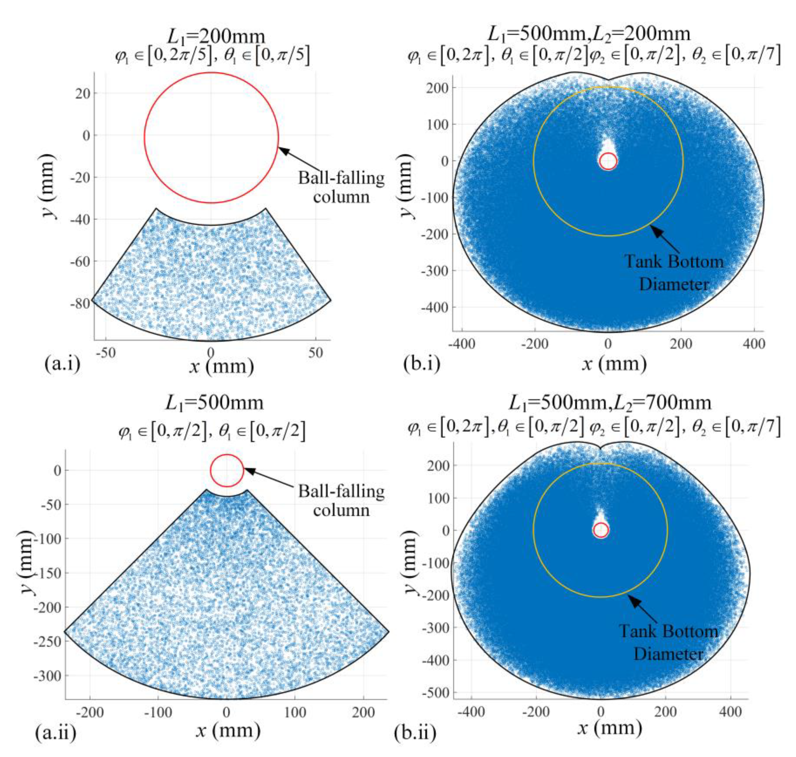
3.4. Workspace Simulation Analysis

The workspace of the continuum robot does not need to cover any position in the ball-storage tank. When the robot enters the tank and starts to suck the ball, a pit will form at the initial suction position. Due to the height difference, the absorber ball at other positions will gradually slide to the bottom along the slope of the pit, and then, under the action of negative pressure, the absorber ball will be transported to the external ball-storage tank along the ball-sucking tube. During this process, as the continuum robot keeps feeding, the height of the absorber balls inside the tank drops until the end-effector moves to the bottom of the tank. So, in order to remove all the absorber balls, the workspace of the continuum robot only needs to be able to reach any position at the bottom of the tank where the absorber balls are located. The remaining positions only need the end arm to stir to destroy the stability of the accumulation of the absorber balls and ensure the continuity of the removal operation.
Based on the search method, the spatial configuration parameters of the continuum robot are set. When the distal segment of the continuum robot passes through the divider plug, the parameters of the distal segment can be set as: φ 1 [ 0 , π / 2 ] , θ 1 [ 0 , π / 2 ] . Select two points on the distal segment—the middle point (in this case, L1 = 200 mm) and the end point (in this case, L1 = 500 mm)—and calculate their respective working spaces, and the workspace of the distal segment under each group of parameters can be obtained, as shown in Figure 8(a.i)–(a.ii). It can be seen that when there is only one arm, the continuum robot can only move on one side of the ball-falling column and cannot move behind it. When the proximal segment of the continuum robot passes through the divider plug, the parameters of the dual-segment continuum robot can be set as: φ 1 [ 0 , 2 π ] , θ 1 [ 0 , π / 2 ] , φ 2 [ 0 , π / 2 ] , and θ 2 [ 0 , π / 2 ] . The workspace of the dual-segment continuum robot under each group of parameters is shown in Figure 8(b.i)–(b.ii). It can be seen that when the length of the proximal arm reaches 200 mm (in this case, L1 = 500 mm, L2 = 200 mm) or more, the dual-segment continuum robot can be in the “S” shape, around the column 180° on the left and right, and the end-effector of the robot can be wound to the back of the ball-falling column to remove absorber balls anywhere on the bottom of the ball-storage tank.

4. Test Prototype

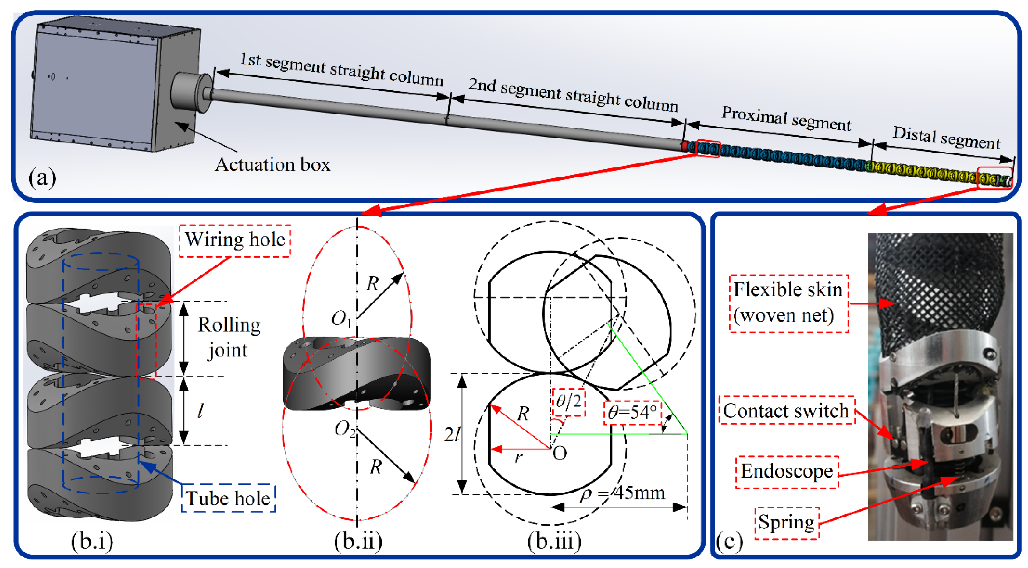
4.1. Prototype of the Dual-Segment Continuum Robot

According to the actual application scenario, the modular and lightweight design of the absorber ball-removal device was carried out and a prototype was manufactured, as shown in Figure 9. The prototype was designed to remove absorbers ball from the ball-storage tank and consists of the continuum robot body, the actuation system, and the absorber ball-removal and control system. In addition, the four corners of the bottom of the ball-storage tank were equipped with weight sensors to weigh the removed absorber balls so as to monitor the removal process (see Figure 9b).
During the installation of the device, in order to ensure the airtightness of the absorber ball shutdown system, the following operations were performed: Firstly, the flange interface was installed with the gas protection device and covered with inner sealing film to form a seal to ensure the airtightness of the shutdown system before the installation of the absorber ball removal device, as shown in Figure 9c. After that, the gas protection device was removed, the device was installed on the flange interface, and the outer sealing film was covered to form a double-layer seal with the inner sealing film. When the continuum robot enters the ball-falling column, the inner sealing film can be torn manually or mechanically.

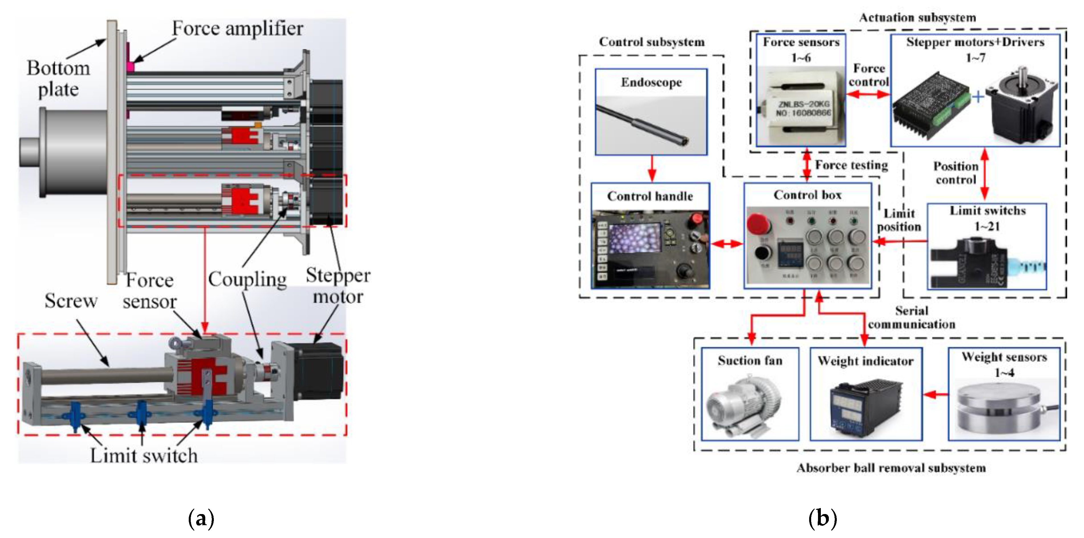
4.2. Actuation and Control System

The actuation and control system mainly includes the actuation box, the control box, and the control handle, with a total of seven motors. Among them, six groups of “stepping motors + screw sliding tables” are used to control the continuum robot, the seventh stepping motor driving the up and down movement of the robot through the synchronous belt and guide rail. To detect the tensile force on the actuation cables for accurate control and overload protection of the continuum robot, a force sensor was installed on each screw slide table and connected with the cable. In addition, limit switches were installed for the calibration and correction of motor travel, as shown in Figure 10a.
The control system can be independently controlled by the control box and the control handle. The control box also integrates the real-time monitoring and display function of the weight sensor, as shown in Figure 10b. In addition, the screen of the control handle can display the endoscope image in real time to assist the ball-suction operation.

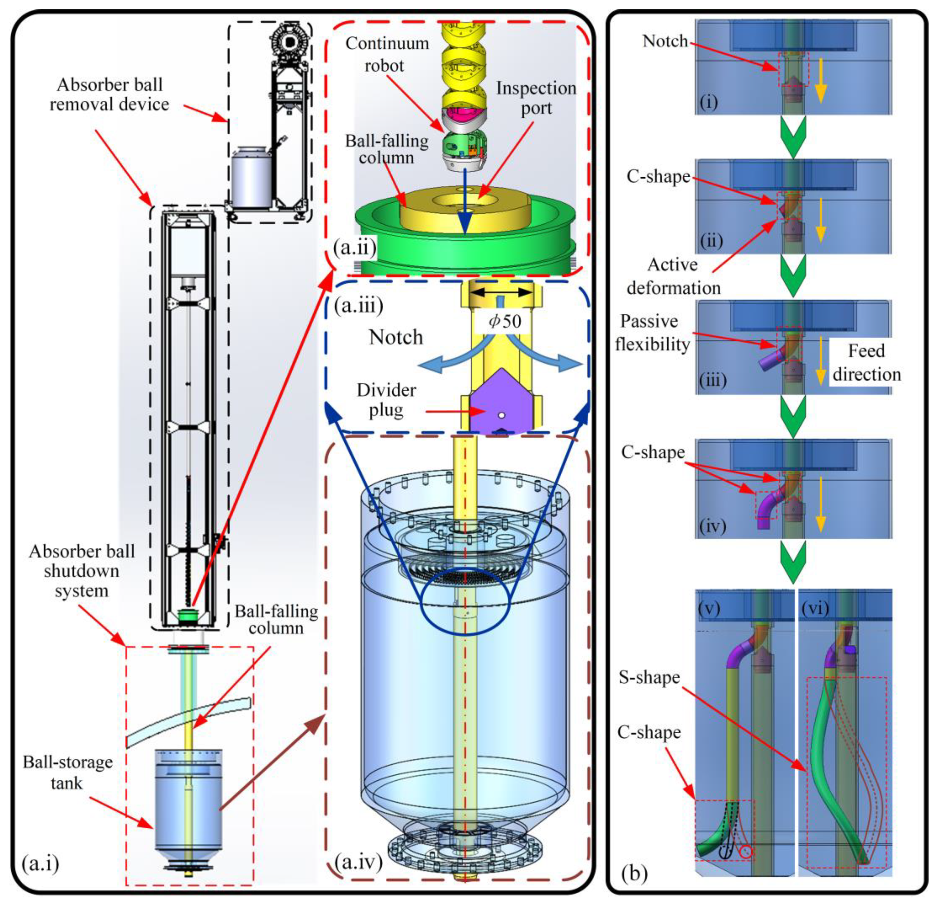
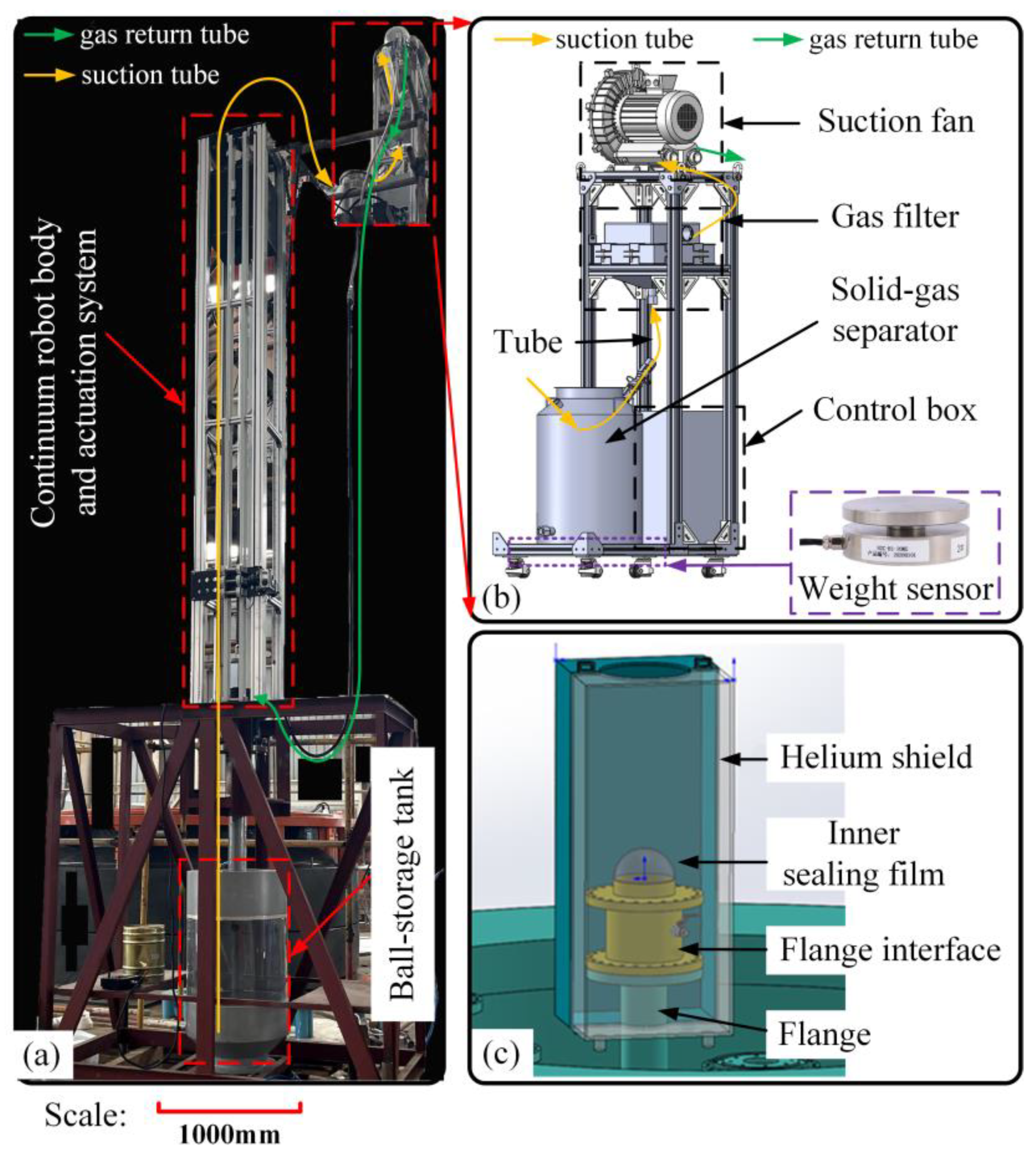
4.3. Absorber Ball Removal System

Negative pressure removal is also known as suction pneumatic conveying mode. As shown in Figure 9a,b, a centrifugal suction fan (YASHIBA (Zhejiang YASHIBA Fan Co., LTD., Taizhou, China): HG-2200; negative pressure: 33 kPa) was adopted as the air source equipment, which is located at the end of the whole conveying system. When the suction fan runs, the whole system creates negative pressure and the absorber balls are sucked into the suction tube along with the gas and transported to the separator to realize the separation of balls and gas. Then, the fine powder particles that have not been separated enter the high-efficiency filter with the airflow for purification along with the purified gas are returned to the reactor by the suction fan through the gas return tube for reuse.
As the whole process is a closed loop, while sucking the absorber balls there will be no negative pressure formed inside the reactor, which effectively protects the high-purity gas environment in the reactor.

5. Prototype Test Verification

To verify a series of functions of the absorber ball-removal device, a functional verification was carried out to determine whether the device can enter and exit a ball-storage tank smoothly (Function 1), whether it can reach any position at the bottom of a ball-storage tank where the absorber balls are located and completely remove the absorber balls (Function 2), and whether the removal efficiency can meet the requirements of the practical engineering application (Function 3). The test requirements were as follows:

5.1. Tests for Functions 1 and 2

The key to function 1 is whether the continuum robot can pass through the divider plug smoothly. The key to function 2 is whether the continuum robot can reach the back of the ball-falling column from the left and right sides, respectively. If so, the robot can reach any position at the bottom of a ball-storage tank where the absorber balls are located and remove all absorber balls. Therefore, the main aims of the test are to control the continuum robot such that it is able to pass through the divider plug and realize left and right 180° movement around the ball-falling column.
Firstly, the continuum robot is controlled to move downwards and the collision detection device of the end-effector is triggered at the divider plug. Then the robot can actively bend towards the notch of the ball-falling column at a given angle to pass through the divider plug. Finally, the end arm of the continuum robot returns to the vertical state and continues to move downwards (passive flexible deformation pose) until the collision detection device is triggered again, stopping the movement, and then the balls start to be sucked. The process is shown in Figure 11. Moreover, due to the existence of the woven net, the outer surface of the robot is smooth and the passive flexible deformation is also smooth so that the device does not get stuck in the divider plug.
After the continuum robot passes through the divider plug and starts to suck the ball, with the gradual removal of the absorber ball, the accumulation line of the absorber ball in the ball-storage tank will gradually move down. On account of this, the continuum robot only needs to move its end arm in a small range, such as a circular-trajectory motion (see Figure 12) and a sector-scanning motion (see Figure 13), the continuous removal of the absorber ball can be ensured by feeding downward in turn. When the end-effector reaches the bottom of the ball-storage tank, the continuum robot needs to realize left and right 180° movement around the ball-falling column to ensure that it can reach any position at the bottom of the ball-storage tank where the absorber balls are located and complete the removal of all of the absorber balls. The movement effect is shown in Figure 14.

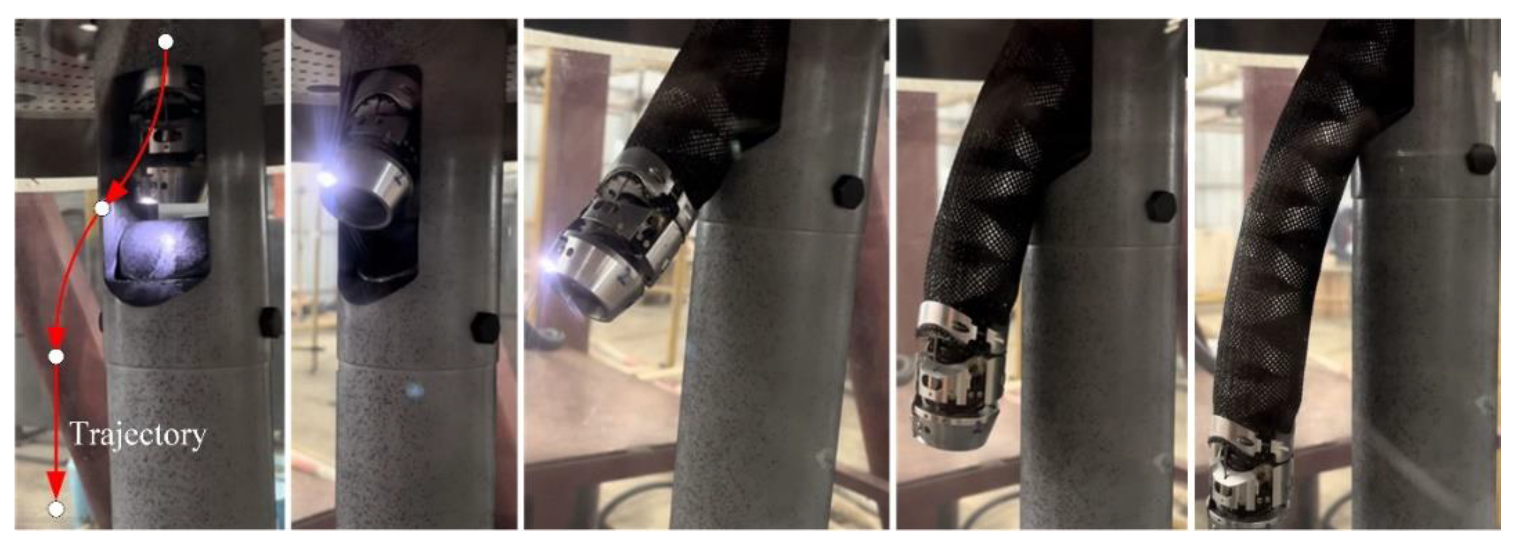
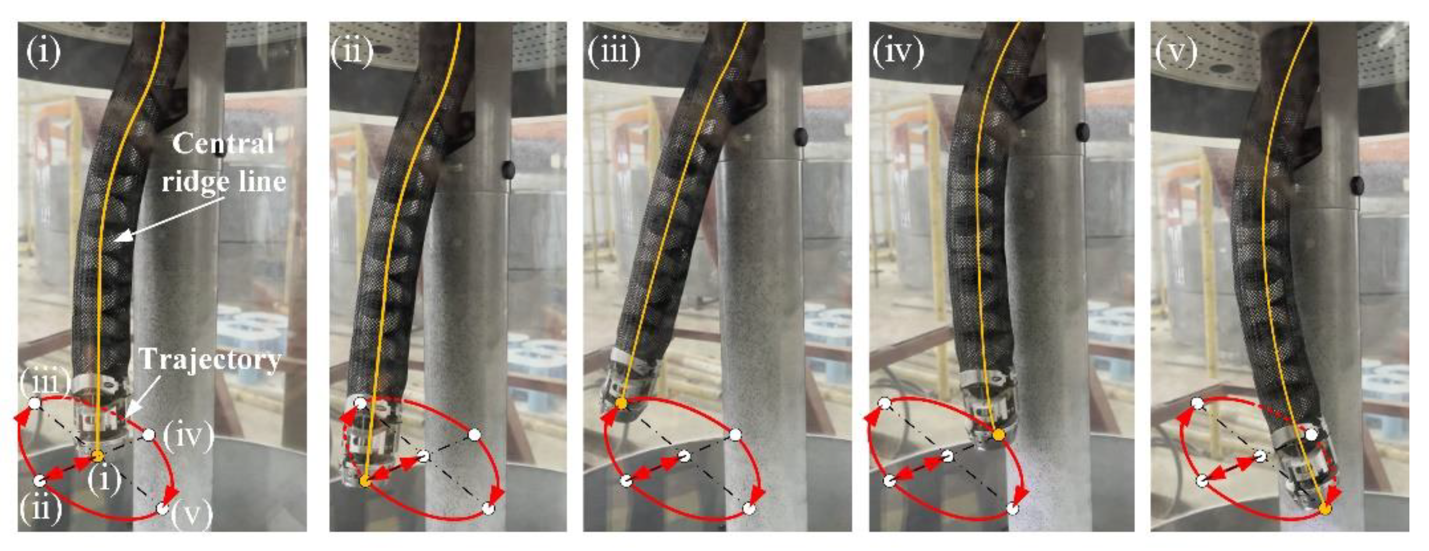
5.2. Test for Function 3

In the engineering test environment, absorber ball-removal efficiency was tested with lift ≥ 6 m. It can be seen from Table 2 and Figure 15 that the efficiency of absorber ball removal is related to the lift, tube material, and diameter. The test results show that, within the test range, the tube diameter is directly proportional to the removal efficiency (Tests 1, 2, 3; 4, 5, 6; 7, 8, 9; 10, 11, 12; 13, 14, 15), while the lift is inversely proportional to the removal efficiency (Tests 10, 13; 11, 14; 12, 15). Among them, the ball-sucking tube of “PVC + steel wire” has the highest removal efficiency in each of their respective groups. However, due to the high viscosity of the tube inner wall, when the suction fan stops running, the absorber ball still in the tube will be blocked in the falling process, affecting the subsequent removal operation. Furthermore, the removal efficiency of the PU tube is the lowest due to the limitation of tube diameter, with which it is easy to form a local vacuum environment in the pipeline. Moreover, the PU tube and “PU + steel wire” tube has strong toughness, which will hinder the passive flexible deformation of the robot arm at the divider plug.
Regarding tube diameter and removal efficiency, the removal efficiency of the EVA tube is higher. Moreover, its material is soft and easy to bend and it can axially expand and contract within a certain range. In addition, considering the limitation of joint inner diameter (25 mm), the EVA tube with a size of 16 × 22 mm can be selected as the ball-sucking tube. It can be seen that the highest efficiency of absorber ball removal can reach 58.96 kg/h with a lift of 7.5 m and 48.54 kg/h with a lift of 10 m in the gas environment, which greatly reduces the cost and time of removing absorber balls.

5.3. Discussion

In this section, we have verified the motion performance (Section 5.1) of the continuum robot and the removal efficiency (Section 5.2) of absorber balls. The field tests showed that the continuum robot was able to smoothly pass through the obstacle (the divider plug) and achieve 180° left and right movements around the column, which enabled the continuum robot to enter the work scene (the ball-storage tank) smoothly and allowed it to remove all of the absorber balls (as it was able to reach any position at the bottom of the ball-storage tank where absorber balls were located; see Figure 8 and Figure 15). Continuum robots have more degrees of freedom, better maneuverability, and a larger sweep area than the steerable catheters commonly used in medical contexts. Usually, the catheters are composed of a single segment with a two-degrees-of-freedom structure which cannot realize movement around the column. Therefore, the catheters need to enter the ball-storage tank from the notch on both sides of the divider plug twice, which increases the complexity of the removal operation. In addition, considering the radioactivity of absorber balls, the material of the steerable catheters is not suitable for multiple reuse in the removal task, which undoubtedly greatly increases maintenance costs. In contrast, the continuum robot is more like a platform with a suction tube that can be changed periodically. Compared to steerable catheters, the cost of simply replacing the suction tube is negligible. This is one of the reasons we chose the right tube and tested its removal efficiency (Section 5.2). Therefore, it is a good choice to use a continuum robot equipped with a ball-suction tube to remove absorber balls with negative pressure.
The device also demonstrated excellent removal capability and high lift (10 m) for pneumatic conveying, which ensured that the device could be operated remotely in a nuclear environment. The results show that this device represents an effective way of developing low-cost, short-cycle, and high-performance robotic systems for nuclear power maintenance tasks, including damage detection of equipment, in bore inspection of pipes, sampling detection of parts of nuclear materials, etc. To our knowledge, this work has produced the first continuum robot system for the the removal of absorber balls, expanding the continuum of robot application scenarios in the nuclear industry.

6. Conclusions

In this article, a new type of in situ inspection and repair technology for HTR nuclear power plants has been proposed for use in the removal of absorber balls from reactor vessels. The main body of the device is a 3-DOF dual-segment continuum robot with a high length-to-diameter ratio (the ratio of the working part is 30 and the overall ratio is 75) based on rolling joints. The distal end of the continuum robot is equipped with an end-effector to perform the removal of absorber balls by pneumatic conveying. In addition, the arm of the continuum robot is covered with a woven net as a “skin”, which has the following flexible deformation ability and can enhance the travelability of the continuum robot in unstructured environments. Compared with the rigid continuum robot, the designed flexible continuum robot only needs two segments to remove absorber balls, which greatly simplifies the control complexity and reduces the cost. It has the following characteristics:
(i)
The lift of pneumatic conveying can reach 10 m and it can realize movement with three degrees of freedom (up and down, left and right, front and back);
(ii)
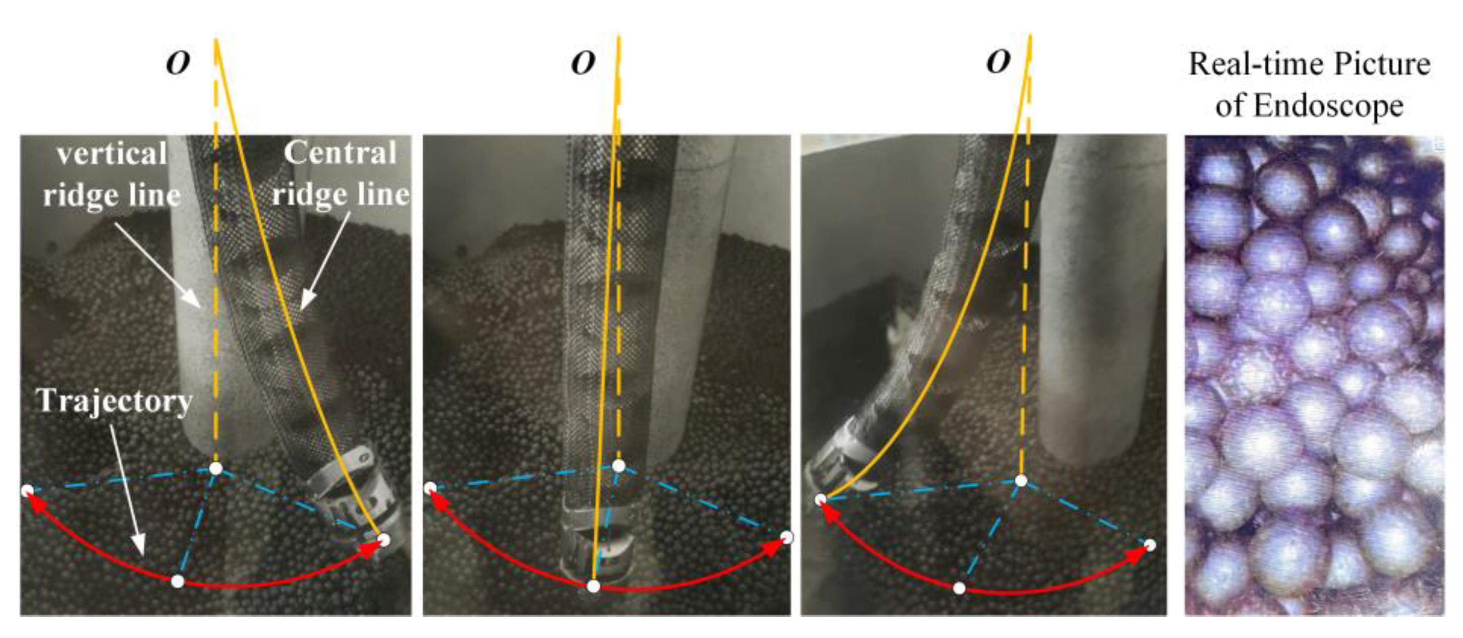
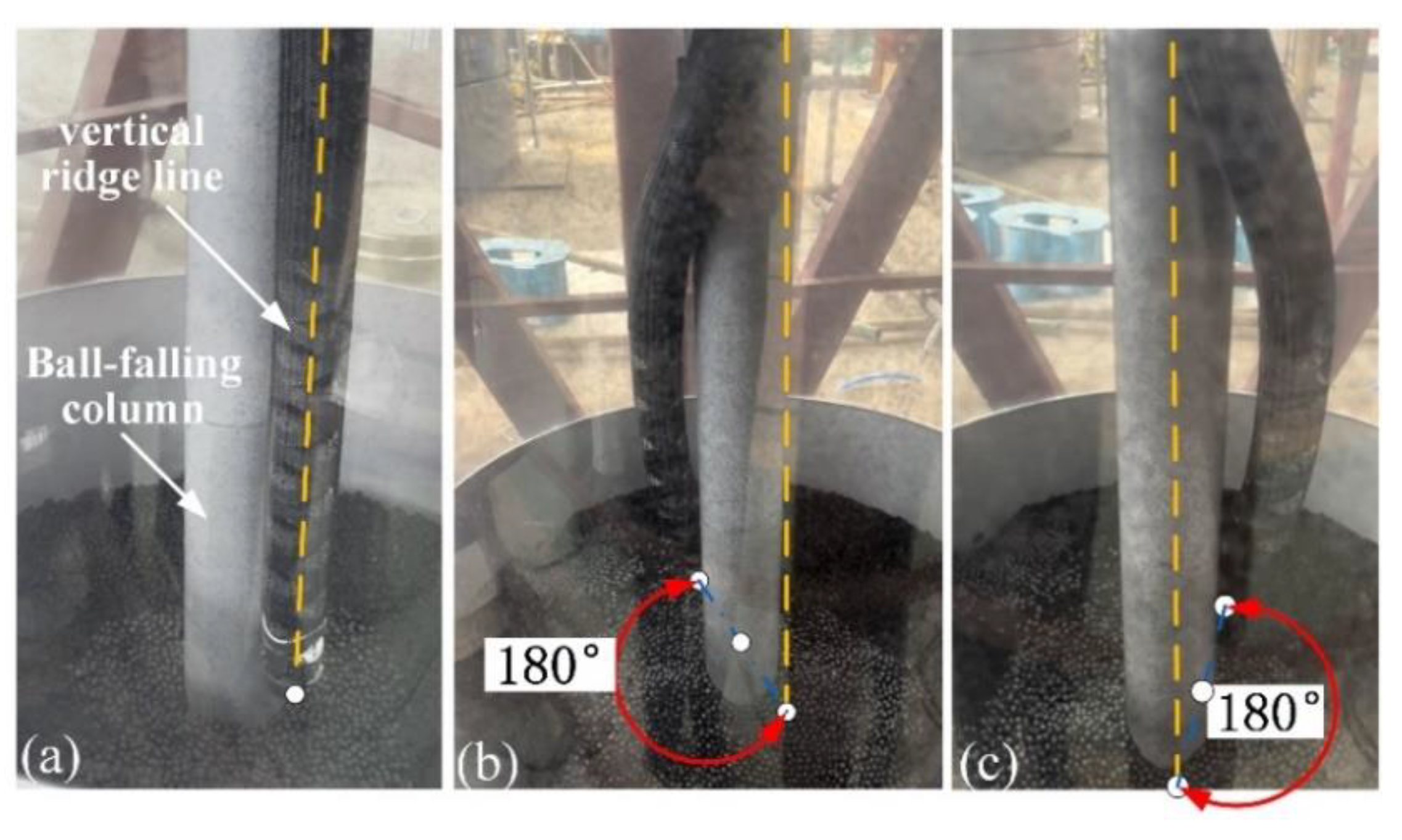
It can pass through the divider plug and realize 360° movement around the ball-falling column;
(iii)
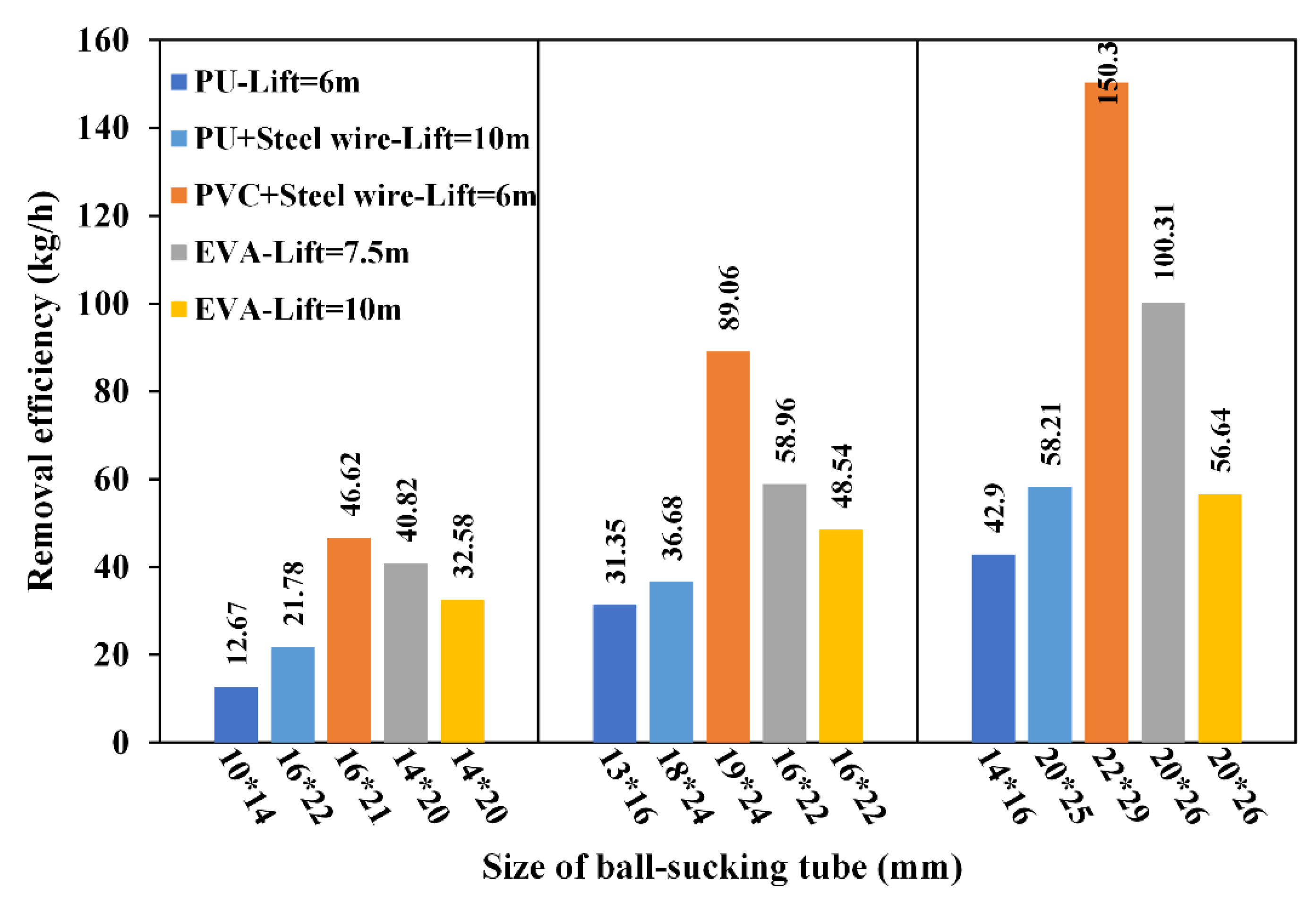
It can realize the function of removing absorber balls and monitor the weight of absorber balls removed;
(iv)
The end-effector is equipped with a light and has a visual function, allowing observation of the removal of absorber balls in real time.
Due to the high flexibility and hyper-redundancy of the continuum robot, the dual-segment continuum robot, which is also the most widely used, has been shown to be able to travel in a general unstructured environment. In order to better complete the removal of absorber balls, the kinematics equation between the length of the actuation ropes l i and the spatial pose θ i , φ i of the dual-segment continuum robot was generalized. Finally, the functions of the absorber ball removal device were verified. The continuum robot can smoothly pass through the divider plug and reach any position at the bottom of a tank where absorber balls are located to complete the removal of the absorber balls. In addition, the removal efficiency of absorber balls can reach 58.96 kg/h with a lift of 7.5 m and 48.54 kg/h with a lift of 10 m in a gas environment. Further, the device can be considered to increase the negative pressure of the tube by connecting the suction fans in series so as to improve removal efficiency.

Author Contributions

G.L.: methodology, writing—original draft preparation; J.Y. (Jingjun Yu): writing—review and editing; D.D.: visualization, investigation; H.W.: software; S.C.: conceptualization; J.P.: data curation; X.P.: writing—review and editing; X.H.: supervision; J.Y. (Jianqing Yi): visualization, investigation. All authors have read and agreed to the published version of the manuscript.

Funding

This research was funded by [the National Natural Science Foundation of China] grant number [No. U1813221] and [the National Key R&D Program of China] grant number [No. 2019YFB1311200].

Conflicts of Interest

The authors declare no conflict of interest.

Appendix A

Table A1. Comparison of relevant characteristics of different continuum robots for nuclear applications.
Driving MethodArm Body StructureApplication ScenariosFunctionCharacteristicsValidation Method
Snake arm maintainer [9]Cable-drivenMulti-segment structure with multi-jointVacuum chamber Platform with end toolsPrinciple of layered drive; reverse foldingComputer simulation
EMMATM manipulator [27,29]Cable-drivenMulti-segment structure with multi-jointWaste Storage Tank Inspection and remediationHigh payload capacity;
oversized body
Practical application
CT Arm [28]Cable-drivenMulti-link structureNuclear reactorMaintenanceCoupled drive; connected differential mechanismComputer simulation
KSI tentacle manipulator [30]Hybrid electric–pneumatic actuationMulti-segment structure with pneumatic bellowsNuclear hot cell decontaminationTeleoperated vacuuming and spray washingExtensibility/retractability in length.Patented
Snake-arm robot (OC Robotics) [31]Cable-drivenMulti-segment structure with single jointNuclear power
plant
Inspection and repair operationsThe only general purpose continuum robot commercially availablePractical application
Proposed robotCable-drivenMulti-segment structure with multi-jointAbsorber ball shutdown systemRemove absorber ballsPneumatic conveying; opposite-bending and feedingEngineering experiment

References

  1. Boustani, E.; Khakshournia, S.; Khalafi, H. A pragmatic approach towards designing a second shutdown system for tehran research reactor. Nucl. Technol. Radiat. Protect. 2016, 31, 28–36. [Google Scholar] [CrossRef] [Green Version]
  2. Zhang, Z.; Dong, Y.; Li, F.; Zhang, Z.; Wang, H.; Huang, X.; Li, H.; Liu, B.; Wu, X.; Wang, H.; et al. The Shandong Shidao Bay 200 MWe High-Temperature Gas-Cooled Reactor Pebble-Bed Module (HTR-PM) Demonstration Power Plant: An Engineering and Technological Innovation. Engineering 2016, 2, 112–118. [Google Scholar] [CrossRef] [Green Version]
  3. Li, T.J.; Zhang, H.; Kuang, S.B.; Yan, H.; Diao, X.Z.; Huang, Z.Y.; Bo, H.L.; Dong, Y.J. Experimental and numerical study of coarse particle conveying in the small absorber sphere system: Overview and some recent CFD-DEM simulations. Nucl. Eng. Des. 2020, 357, 110420. [Google Scholar] [CrossRef]
  4. Li, T.; Zhang, H.; Liu, M.; Huang, Z.; Bo, H.; Dong, Y. DEM study of granular discharge rate through a vertical pipe with a bend outlet in small absorber sphere system. Nucl. Eng. Des. 2017, 314, 1–10. [Google Scholar] [CrossRef]
  5. Trevelyan, J.; Hamel, W.R.; Kang, S.-C. Robotics in hazardous applications. In Springer Handbook of Robotics; Siciliano, B., Khatib, O., Eds.; Springer International Publishing: Cham, Switzerland, 2016; pp. 1521–1548. [Google Scholar]
  6. Grazioso, S.; di Gironimo, G.; Siciliano, B. Modeling and vibration control of flexible mechanical systems for DEMO remote maintenance: Results from the FlexARM project. Fusion Eng. Des. 2019, 146, 1423–1425. [Google Scholar] [CrossRef]
  7. Angrisani, L.; Grazioso, S.; Gironimo, G.D.; Panariello, D.; Tedesco, A. On the use of soft continuum robots for remote measurement tasks in constrained environments: A brief overview of applications. In Proceedings of the 2019 IEEE International Symposium on Measurements & Networking (M&N), Catania, Italy, 8–10 July 2019; pp. 1–5. [Google Scholar]
  8. Liu, Y.; Yan, Q.; Zhang, Q.; Guo, W.; Odbal; Wu, B.; Wang, Z. Control system design and implementation of flexible multi-joint snake-like robot for inspecting vessel. In Proceedings of the 14th International Conference on Intelligent Autonomous Systems (IAS), Shanghai, China, 3–7 July 2016; pp. 1037–1047. [Google Scholar]
  9. Qin, G.; Cheng, Y.; Pan, H.; Zhao, W.; Shi, S.; Ji, A.; Wu, H. Systematic design of snake arm maintainer in nuclear industry. Fusion Eng. Des. 2022, 176, 113049. [Google Scholar] [CrossRef]
  10. Keogh, K.; Kirk, S.; Suder, W.; Farquhar, I.; Tremethick, T.; Loving, A. Laser cutting and welding tools for use in-bore on EU-DEMO service pipes. Fusion Eng. Des. 2018, 136, 461–466. [Google Scholar] [CrossRef] [Green Version]
  11. Silva Rico, J.A.; Endo, G.; Hirose, S.; Yamada, H. Development of an actuation system based on water jet propulsion for a slim long-reach robot. ROBOMECH J. 2017, 4, 8. [Google Scholar] [CrossRef]
  12. Robinson, G.; Davies, J.B.C. Continuum robots—A state of the art. In Proceedings of the International Conference on Robotics and Automation (ICRA ‘99), Detroit, MI, USA, 10–15 May 1999; pp. 2849–2854. [Google Scholar]
  13. Chirikjian, G. Theory and Applications of Hyper-Redundant Robotic Manipulators; California Institute of Technology: Pasadena, CA, USA, 1992. [Google Scholar]
  14. Buckingham, R.; Graham, A. Snaking around in a nuclear jungle. Ind. Robot. Int. J. 2005, 32, 120–127. [Google Scholar] [CrossRef]
  15. Axinte, D.; Dong, X.; Palmer, D.; Rushworth, A.; Guzman, S.C.; Olarra, A.; Arizaga, I.; Gomez-Acedo, E.; Txoperena, K.; Pfeiffer, K.; et al. Miror-miniaturized robotic systems for holistic in-situ repair and maintenance works in restrained and hazardous environments. IEEE ASME Trans. Mechatron. 2018, 23, 978–981. [Google Scholar] [CrossRef]
  16. Dong, X.; Axinte, D.; Palmer, D.; Cobos, S.; Raffles, M.; Rabani, A.; Kell, J. Development of a slender continuum robotic system for on-wing inspection/repair of gas turbine engines. Rob. Comput. Integr. Manuf. 2017, 44, 218–229. [Google Scholar] [CrossRef] [Green Version]
  17. Qi, F.; Chen, B.; Gao, S.; She, S. Dynamic model and control for a cable-driven continuum manipulator used for minimally invasive surgery. Int. J. Med. Rob. Comput. Assisted Surg. 2021, 17, e2234. [Google Scholar] [CrossRef] [PubMed]
  18. Zhong, Y.; Hu, L.H.; Xu, Y.S. Recent advances in design and actuation of continuum robots for medical applications. Actuators 2020, 9, 142. [Google Scholar] [CrossRef]
  19. Kim, Y.; Parada, G.A.; Liu, S.; Zhao, X. Ferromagnetic soft continuum robots. Sci. Rob. 2019, 4, eaax7329. [Google Scholar] [CrossRef] [PubMed]
  20. Burgner-Kahrs, J.; Rucker, D.C.; Choset, H. Continuum robots for medical applications: A survey. IEEE Trans. Rob. 2015, 31, 1261–1280. [Google Scholar] [CrossRef]
  21. Nahar, D.; Yanik, P.M.; Walker, I.D. Robot tendrils: Long, thin continuum robots for inspection in space operations. In Proceedings of the IEEE Aerospace Conference, Big Sky, MT, USA, 4–11 March 2017. [Google Scholar]
  22. Liljeback, P.; Mills, R. Eelume: A flexible and subsea resident IMR vehicle. In Proceedings of the Oceans Aberdeen Conference, Aberdeen, UK, 19–22 June 2017. [Google Scholar]
  23. Lee, K.; Wang, Y.; Zheng, C. Twister hand: Underactuated robotic gripper inspired by origami twisted tower. IEEE Trans. Rob. 2020, 36, 488–500. [Google Scholar] [CrossRef]
  24. Wang, M.; Dong, X.; Ba, W.; Mohammad, A.; Axinte, D.; Norton, A. Design, modelling and validation of a novel extra slender continuum robot for in-situ inspection and repair in aeroengine. Rob. Comput. Integr. Manuf. 2021, 67, 102054. [Google Scholar] [CrossRef]
  25. Simaan, N.; Taylor, R.; Flint, P. A dexterous system for laryngeal surgery. In Proceedings of the IEEE International Conference on Robotics and Automation, New Orleans, LA, USA, 26 April–1 May 2004; pp. 351–357. [Google Scholar]
  26. Chitalia, Y.; Jeong, S.; Yamamoto, K.K.; Chern, J.J.; Desai, J.P. Modeling and control of a 2-dof meso-scale continuum robotic tool for pediatric neurosurgery. IEEE Trans. Rob. 2021, 37, 520–531. [Google Scholar] [CrossRef]
  27. Bostelman, R.V.; Albus, J.S.; Graham, R.E. Robocrane and EMMA applied to waste storage tank remediation. In Proceedings of the American Nucelar Society Seventh Topical Meeting on Robotics and Remote Systems, Augusta, GA, USA, 27 April–1 May 1997; pp. 708–713. [Google Scholar]
  28. Ma, S.; Hirose, S.; Yoshinada, H. Development of a hyper-redundant multijoint manipulator for maintenance of nuclear reactors. Adv. Rob. 1994, 9, 281–300. [Google Scholar] [CrossRef]
  29. Marschke, S.F. West Valley Demonstration Project, Waste Management Area# 3—Closure Alternative I; Environmental Measurements Laboratory (EML): New York, NY, USA, 2000. [Google Scholar] [CrossRef]
  30. Immega, G.; Antonelli, K. The KSI tentacle manipulator. In Proceedings of the 1995 IEEE International Conference on Robotics and Automation, Nagoya, Japan, 21–27 May 1995; pp. 3149–3154. [Google Scholar] [CrossRef]
  31. Buckingham, R.; Graham, A. Nuclear snake-arm robots. Ind. Robot. Int. J. 2012, 39, 6–11. [Google Scholar] [CrossRef]
  32. Buckingham, R.; Chitrakaran, V.; Conkie, R.; Ferguson, G.; Graham, A.; Lazell, A.; Lichon, M.; Parry, N.; Pollard, F.; Kayani, A. Snake-Arm Robots: A New Approach to Aircraft Assembly; SAE Technical Paper; SAE International: Warrendale, PA, USA, 2007. [Google Scholar] [CrossRef]
Figure 1. Working scene of the continuum robot. (a.i) Working scene. (a.ii) Inspection port. (a.iii) Divider plug and rectangular notch. (a.iv) Ball-storage tank. The continuum robot system is mounted on the reserved detachable interface and performs the removal operation. (b) Access (in/out) strategy. (i) The continuum robot enters at the inspection port and moves down to the divider plug. (ii) The end arm of the continuum robot actively bends at a certain angle towards the notch on one side of the divider plug and (iii,iv) continues to move downward, the residual arm of continuum robot passing through the divider plug in the passive flexible deformation pose. Then, the end arm will actively bend to the original state (vertical downward) and continue to move downward, these constituting the opposite-bending and feeding characteristics. (v,vi) When it reaches the bottom of the tank, the continuum robot will produce C-shape and S-shape bending to remove the absorber ball ( d = 6   mm , m 0.24   g ) at the bottom plane of the ball-storage tank.
Machines 10 00596 g001
Figure 2. Design of the dual-segment continuum robot: (a) whole configuration; (b.i) the way the joints are combined; (b.ii) the basic configuration of the rolling joint; (b.iii) the reachable bending angles of the rolling joints (half stroke); (c) the structure and composition of the end-effector.
Machines 10 00596 g002
Figure 3. Passive flexible deformation of the robot arm. Points A and B are the intersection points between the continuum robot and the inclined plane of the divider plug, and point A is the tangent point. d and d1 are the diameters of the ball-falling column and the continuum robot, respectively, and d2 is the height of the rectangular notch. x is the distance between point A and the center line O–O.
Machines 10 00596 g003
Figure 4. Mapping between the driving space and the joint space of the distal segment. (a) Bending configuration of the distal segment. (b) Positional layout of the actuation cables.
Machines 10 00596 g004
Figure 5. Equivalent diagram of the actuation cables at the proximal segment.
Machines 10 00596 g005
Figure 6. Pose transformation based on the constant curvature model.
Machines 10 00596 g006
Figure 7. Inverse kinematics model of the continuum robot.
Machines 10 00596 g007
Figure 8. Reachable workspace of the continuum robot: (a.i,a.ii) workspace of the distal segment ( L 1 = 200   mm   and   500   mm ); (b.i,b.ii) workspace of the dual-segment continuum robot ( L 1 = 500   mm , L 2 = 200   mm   and   700   mm ).
Machines 10 00596 g008
Figure 9. Test prototype of the continuum robot. The yellow arrow indicates the suction tube and the green arrow indicates the gas return tube. (a) Test prototype. (b) Negative pressure-removal and control system. (c) Helium protection device.
Machines 10 00596 g009
Figure 10. The actuation and control system. (a) Structure and composition of the actuation box. (b) Block diagram of the control system.
Machines 10 00596 g010
Figure 11. Trajectory for passing through the divider plug.
Machines 10 00596 g011
Figure 12. Circular-trajectory motion of the suction ball. (i–v) Points of the selected circular trajectory.
Machines 10 00596 g012
Figure 13. Sector-scanning motion of the suction ball.
Machines 10 00596 g013
Figure 14. Test of the continuum robot around the column: (a) initial state; (b) 180° left around the column; (c) 180° right around the column.
Machines 10 00596 g014
Figure 15. Removal efficiency of absorber balls in the gas environment.
Machines 10 00596 g015
Table 1. The parameters of the continuum robot.
ParameterSymbolValue
Total lengthL3000 mm
Length of the distal segmentL1500 mm
Length of the proximal segmentL2700 mm
Length of the straight columnLs900 mm
Joint outer radiusr40 mm
Joint inner radius---12.5 mm
Joint lengthl20 mm
Number of jointsn60
Length–diameter ratio---75
Table 2. Removal efficiency tests for absorber ball removal in a gas environment.
TestSuction Fan/WLift/mMaterialSize */mmTime/s
112006PU10 *1460
213 *1660
314 *1660
4220010PU
+
Steel wire
16 *2260
518 *2460
620 *2560
722006PVC
+
Steel wire
16 *2130
819 *2430
922 *2930
1022007.5EVA
(corrugated shape)
14 *2030
1116 *2230
1220 *2630
1322001014 *2030
1416 *2230
1520 *2630
Size *: inner diameter *outer diameter of the ball-sucking tube. (The following statements are the same).
Publisher’s Note: MDPI stays neutral with regard to jurisdictional claims in published maps and institutional affiliations.

