
Thruster Fault Diagnostics and Fault Tolerant Control for Autonomous Underwater Vehicle with Ocean Currents

Abstract
:1. Introduction
2. Mathematical Models of AUV
2.1. Problem Description
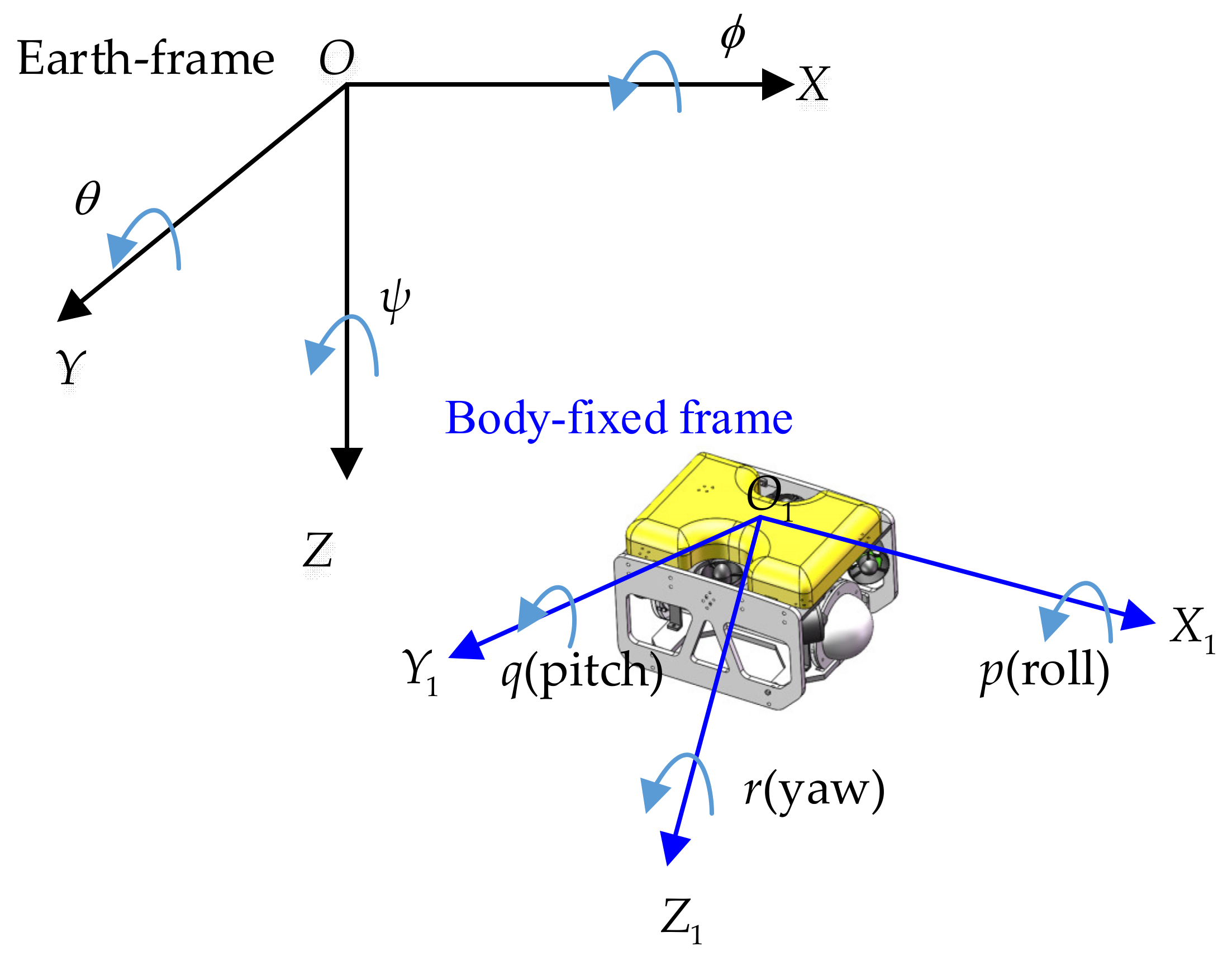
2.2. AUV KINEMATIC model
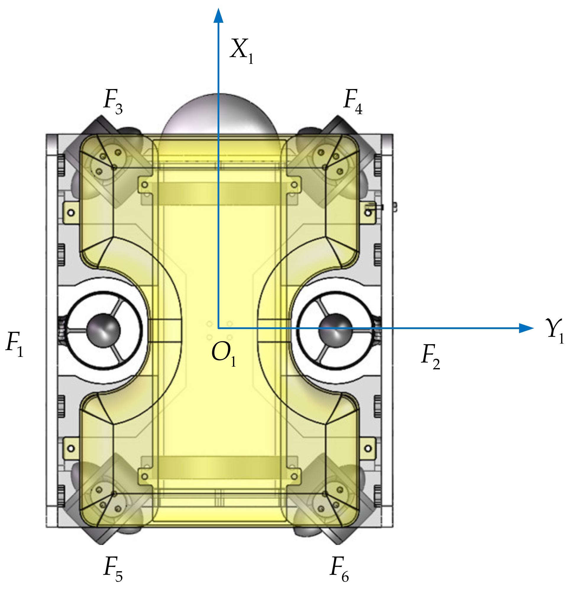
2.3. AUV Dynamic Model
3. Thruster Fault Diagnostics and Fault Tolerant Control
3.1. Thruster Fault Diagnostics for AUV
3.2. Fault Tolerant Control for AUV
3.3. Robust Optimization for AUV
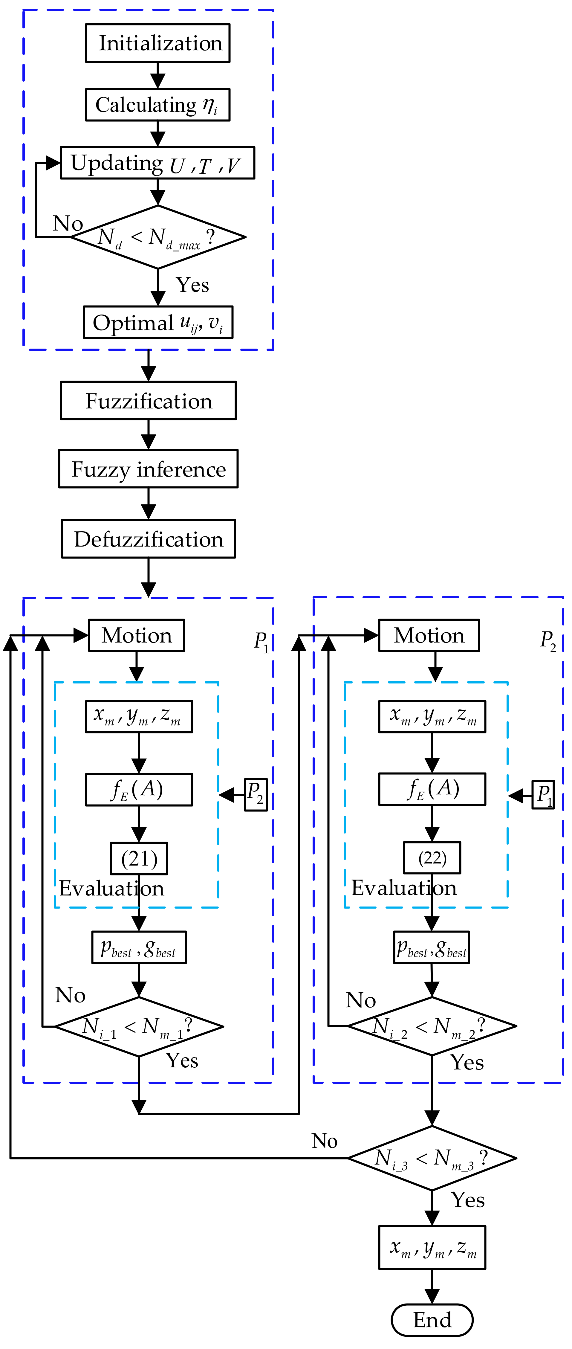
3.4. Thruster Fault Diagnostics and Fault Tolerant Control Algorithm
| Algorithm 1: Thruster fault diagnostics and fault tolerant control for AUV |
| 1: Initializing the parameters , , , , and so on for thruster fault diagnostics; |
| 2: Calculating the penalty factor based on Equation (14), updating , , based on Equations (15)–(17) respectively; |
| 3: If the iterations are smaller than the given maximum number of times (), obtaining the final , , ; else if go to Step 2. |
| 4: Considering the effects of ocean currents, establishing the robust optimization model for AUV fault tolerant control systems. |
| 5: Establishing the models of the evaluation functions (21) and (22) for and respectively. |
| 6: Initializing the two populations randomly, evaluating each population co-evolutionarily by using (21) and (22), respectively. |
| 7: Evolving the population based on (21); replacing the global best () and personal best () particle positions. |
| 8: If the iterations () is smaller than the given maximum number of times (), go to the next step, else if go to Step 7. |
| 9: Evolving the population based on (22); replacing and particle positions. |
| 10: If the iterations are smaller than the given maximum number of times (), go to the next step, else if, go to step 9. |
| 11: If the iterations are smaller than the given maximum number of times (), obtaining the optimal parameters of the membership function, then getting the final tracking points, end the program; else if go to Step 6. |
4. Simulation and Experiment Analysis
5. Conclusions
Author Contributions
Funding
Institutional Review Board Statement
Informed Consent Statement
Data Availability Statement
Conflicts of Interest
References
- Yin, B.; Zhang, M.; Lin, X.; Fang, J.; Su, S. A fault diagnosis approach for autonomous underwater vehicle thrusters using time-frequency entropy enhancement and boundary constraint–assisted relative gray relational grade. Proc. Inst. Mech. Eng. Part I J. Syst. Control. Eng. 2019, 234, 512–526. [Google Scholar] [CrossRef]
- Yuan, J.; Wan, J.; Zhang, W.; Liu, H.; Zhang, H.; Syahputra, R. An Underwater Thruster Fault Diagnosis Simulator and Thrust Calculation Method Based on Fault Clustering. J. Robot. 2021, 2021, 6635494. [Google Scholar] [CrossRef]
- Kadiyam, J.; Parashar, A.; Mohan, S.; Deshmukh, D. Actuator fault-tolerant control study of an underwater robot with four rotatable thrusters. Ocean Eng. 2020, 197, 106929. [Google Scholar] [CrossRef]
- Che, G. Single critic network based fault-tolerant tracking control for underactuated AUV with actuator fault. Ocean Eng. 2022, 254, 111380. [Google Scholar] [CrossRef]
- Sun, Y.; Ran, X.; Li, Y.; Zhang, G.; Zhang, Y. Thruster fault diagnosis method based on Gaussian particle filter for autonomous underwater vehicles. Int. J. Nav. Archit. Ocean. Eng. 2016, 8, 243–251. [Google Scholar] [CrossRef] [Green Version]
- Jiang, Y.; Feng, C.; He, B.; Guo, J.; Wang, D.; Lv, P. Actuator fault diagnosis in autonomous underwater vehicle based on neural network. Sens. Actuators A Phys. 2021, 324, 112668. [Google Scholar] [CrossRef]
- Yu, D.; Zhu, C.; Zhang, M.; Liu, X. Experimental Study on Multi-Domain Fault Features of AUV with Weak Thruster Fault. Machines 2022, 10, 236. [Google Scholar] [CrossRef]
- Xia, S.; Zhou, X.; Shi, H.; Li, S.; Xu, C. A fault diagnosis method based on attention mechanism with application in Qianlong-2 autonomous underwater vehicle. Ocean Eng. 2021, 233, 109049. [Google Scholar] [CrossRef]
- Raanan, B.Y.; Bellingham, J.; Zhang, Y.; Kemp, M.; Kieft, B.; Singh, H. Detection of unanticipated faults for autonomous underwater vehicles using online topic models. J. Field Robot. 2017, 35, 705–716. [Google Scholar] [CrossRef] [Green Version]
- Liu, X.; Zhang, M.; Yao, F. Adaptive fault tolerant control and thruster fault reconstruction for autonomous underwater vehicle. Ocean Eng. 2018, 155, 10–23. [Google Scholar] [CrossRef]
- Liu, F.; Tang, H.; Luo, J.; Bai, L.; Pu, H. Fault-tolerant control of active compensation toward actuator faults: An autonomous underwater vehicle example. Appl. Ocean. Res. 2021, 110, 102597. [Google Scholar] [CrossRef]
- Zhu, C.; Huang, B.; Zhou, B.; Su, Y.; Zhang, E. Adaptive model-parameter-free fault-tolerant trajectory tracking control for autonomous underwater vehicles. ISA Trans. 2021, 114, 57–71. [Google Scholar] [CrossRef] [PubMed]
- Lv, T.; Zhou, J.; Wang, Y.; Gong, W.; Zhang, M. Sliding mode based fault tolerant control for autonomous underwater vehicle. Ocean Eng. 2020, 216, 107855. [Google Scholar] [CrossRef]
- Li, X.; Chao, H.; Wang, J.; Xu, Q.; Yang, K.; Mao, D. An Iterative Learning Extended-State Observer-Based Fuzzy Fault-Tolerant Control Approach for AUVs. Mar. Technol. Soc. J. 2021, 55, 33–46. [Google Scholar] [CrossRef]
- Che, G.; Yu, Z. Neural-network estimators based fault-tolerant tracking control for AUV via ADP with rudders faults and ocean current disturbance. Neurocomputing 2020, 411, 442–454. [Google Scholar] [CrossRef]
- Wang, L.; Liu, L.; Qi, J.; Peng, W. Improved Quantum Particle Swarm Optimization Algorithm for Offline Path Planning in AUVs. IEEE Access 2020, 8, 143397–143411. [Google Scholar] [CrossRef]
- Cao, X.; Sun, H.; Jan, G.E. Multi-AUV cooperative target search and tracking in unknown underwater environment. Ocean Eng. 2018, 150, 1–11. [Google Scholar] [CrossRef]
- Taheri, E.; Ferdowsi, M.H.; Danesh, M. Closed-loop randomized kinodynamic path planning for an autonomous underwater vehicle. Appl. Ocean. Res. 2019, 83, 48–64. [Google Scholar] [CrossRef]
- Mahmoud Zadeh, S.; Yazdani, A.M.; Sammut, K.; Powers, D.M.W. Online path planning for AUV rendezvous in dynamic cluttered undersea environment using evolutionary algorithms. Appl. Soft Comput. 2018, 70, 929–945. [Google Scholar] [CrossRef] [Green Version]
- Karkoub, M.; Wu, H.-M.; Hwang, C.-L. Nonlinear trajectory-tracking control of an autonomous underwater vehicle. Ocean Eng. 2017, 145, 188–198. [Google Scholar] [CrossRef]
- Chen, H.; Chai, Z.; Dogru, O.; Jiang, B.; Huang, B. Data-Driven Designs of Fault Detection Systems via Neural Network-Aided Learning. IEEE Trans. Neural Netw. Learn. Syst. 2021; ahead of print. [Google Scholar] [CrossRef]
- Chen, H.; Li, L.; Shang, C.; Huang, B. Fault Detection for Nonlinear Dynamic Systems With Consideration of Modeling Errors: A Data-Driven Approach. IEEE Trans. Cyber. 2022, 1–11. [Google Scholar] [CrossRef] [PubMed]
- Chen, J.; Zhang, H.; Pi, D.; Kantardzic, M.; Yin, Q.; Liu, X. A Weight Possibilistic Fuzzy C-Means Clustering Algorithm. Sci. Programm. 2021, 2021, 9965813. [Google Scholar] [CrossRef]
- Fazel Zarandi, M.H.; Sotodian, S.; Castillo, O. A New Validity Index for Fuzzy-Possibilistic C-Means Clustering. Sci. Iran. 2021, 28, 2277–2293. [Google Scholar] [CrossRef]
- Askari, S. Fuzzy C-Means clustering algorithm for data with unequal cluster sizes and contaminated with noise and outliers: Review and development. Expert Syst. Appl. 2021, 165, 1–27. [Google Scholar] [CrossRef]
- Ran, G.; Liu, J.; Li, C.; Lam, H.-K.; Li, D.; Chen, H. Fuzzy-Model-Based Asynchronous Fault Detection for Markov Jump Systems with Partially Unknown Transition Probabilities: An Adaptive Event-Triggered Approach. IEEE Trans. Fuzzy Syst. 2022. [Google Scholar] [CrossRef]
- Ran, G.; Li, C.; Rathinasamy, S.; Han, C.; Wang, B.; Liu, J. Adaptive Event-Triggered Asynchronous Control for Interval Type-2 Fuzzy Markov Jump Syst with Cyber-Attacks. IEEE Trans. Control. Netw. Syst. 2022, 9, 88–99. [Google Scholar] [CrossRef]
- Ran, G.; Chen, H.; Li, C.; Ma, G.; Jiang, B. A Hybrid Design of Fault Detection for Nonlinear Syst Based on Dynamic Optimization. IEEE Trans. Neural Netw Learn. Syst. 2022. [Google Scholar] [CrossRef]
- Cramer, A.M.; Sudhoff, S.D.; Zivi, E.L. Evolutionary Algorithms for Minimax Problems in Robust Design. IEEE Trans. Evol. Comput. 2009, 13, 444–453. [Google Scholar] [CrossRef]
- Tian, Q.; Zhao, D.; Li, Z.; Zhu, Q. A two-step co-evolutionary particle swarm optimization approach for CO2 pipeline design with multiple uncertainties. Carbon Manag. 2018, 9, 333–346. [Google Scholar] [CrossRef]


| NB | NM | NS | ZO | PS | PM | PB | |
|---|---|---|---|---|---|---|---|
| NB | NB | NB | NM | NS | NS | ZO | PM |
| NM | NB | NM | NS | ZO | ZO | PS | PM |
| NS | NB | NM | NS | ZO | PS | PS | PM |
| ZO | NB | NM | NS | ZO | PS | PM | PB |
| PS | NM | NS | NS | ZO | PS | PM | PB |
| PM | NM | NS | ZO | ZO | PS | PM | PB |
| PB | NM | ZO | PS | PS | PM | PB | PB |
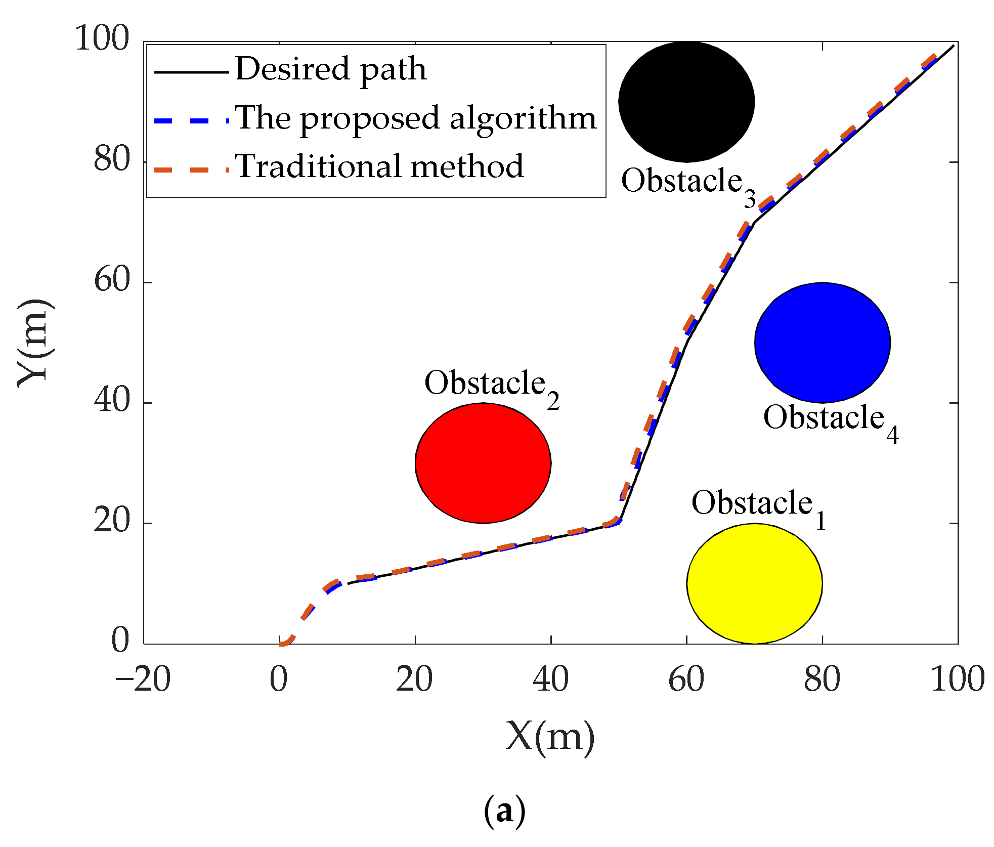
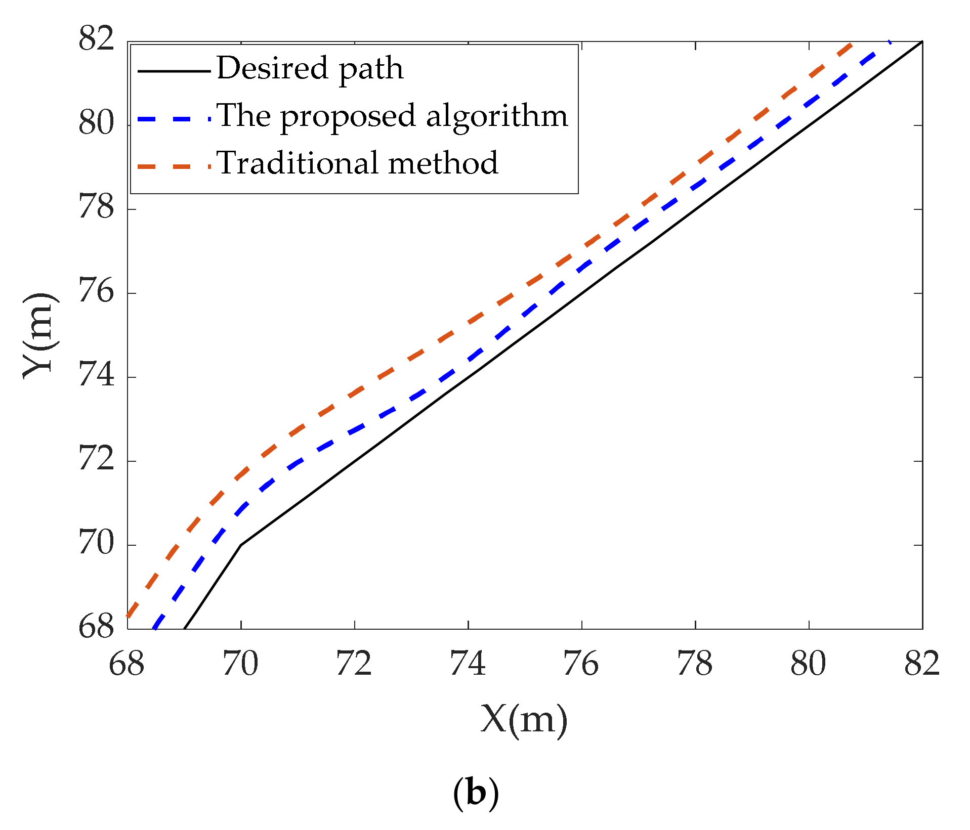
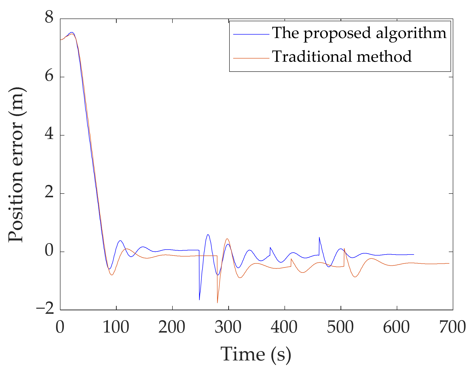
| Method | Path Length (m) | Mean Tracking Error (m) | Standard Deviation (m) |
|---|---|---|---|
| The proposed algorithm | 150.54 | 0.78 | 0.18 |
| Traditional method | 152.71 | 0.92 | 0.22 |
Publisher’s Note: MDPI stays neutral with regard to jurisdictional claims in published maps and institutional affiliations. |
© 2022 by the authors. Licensee MDPI, Basel, Switzerland. This article is an open access article distributed under the terms and conditions of the Creative Commons Attribution (CC BY) license (https://creativecommons.org/licenses/by/4.0/).
Share and Cite
Tian, Q.; Wang, T.; Liu, B.; Ran, G. Thruster Fault Diagnostics and Fault Tolerant Control for Autonomous Underwater Vehicle with Ocean Currents. Machines 2022, 10, 582. https://doi.org/10.3390/machines10070582
Tian Q, Wang T, Liu B, Ran G. Thruster Fault Diagnostics and Fault Tolerant Control for Autonomous Underwater Vehicle with Ocean Currents. Machines. 2022; 10(7):582. https://doi.org/10.3390/machines10070582
Chicago/Turabian StyleTian, Qunhong, Tao Wang, Bing Liu, and Guangtao Ran. 2022. "Thruster Fault Diagnostics and Fault Tolerant Control for Autonomous Underwater Vehicle with Ocean Currents" Machines 10, no. 7: 582. https://doi.org/10.3390/machines10070582