Article

Stiffness-Tuneable Segment for Continuum Soft Robots with Vertebrae

1
Hefei Institutes of Physical Science, Chinese Academy of Sciences, Hefei 230031, China
2
University of Science and Technology of China, Hefei 230026, China
3
College of Mechanical and Electrical Engineering, Hohai University, Changzhou 213002, China
4
Changzhou Vocational Institute of Industry Technology, Changzhou 213164, China
*
Author to whom correspondence should be addressed.
These authors contributed equally to this work.
Machines 2022, 10(7), 581; https://doi.org/10.3390/machines10070581
Submission received: 8 June 2022 / Revised: 3 July 2022 / Accepted: 13 July 2022 / Published: 18 July 2022
(This article belongs to the Special Issue Bio-Inspired Smart Machines: Structure, Mechanisms and Applications)

Abstract

:
In addition to high compliance to unstructured environments, soft robots can be further improved to gain the advantages of rigid robots by increasing stiffness. Indeed, realizing the adjustable stiffness of soft continuum robots can provide safer interactions with objects and greatly expand their application range. To address the above situation, we propose a tubular stiffening segment based on layer jamming. It can temporarily increase the stiffness of the soft robot in a desired configuration. Furthermore, we also present a spine-inspired soft robot that can provide support in tubular segments to prevent buckling. Theoretical analysis was conducted to predict the stiffness variation of the robot at different vacuum levels. Finally, we integrated the spine-inspired soft robot and tubular stiffening segment to obtain the tuneable-stiffness soft continuum robot (TSCR). Experimental tests were performed to evaluate the robot’s shape control and stiffness tuning effectiveness. Experimental results showed that the bending stiffness of the initial TSCR increased by more than 15× at 0°, 30× at 90°, and 60× in compressive stiffness.

1. Introduction

Compared to traditional rigid robots, the key advantages of continuum robots are that their weight is lower for the same output force and they are inherently compliant. The structural characteristics of the continuum determine that it has more degrees of freedom, higher dexterity, and can adapt to the shape of various objects, and their ends can be positioned to more 3D space positions. In addition, the simple structure and high compliance of continuum robots are beneficial to improve the safety of human–robot interaction and directly handle sensitive subjects. Continuum robots have also greatly enriched the application field of robots, such as exploration [1], object manipulation [2,3], and surgical applications [4,5]. The most remarkable and common application is invasive surgery. According to the structure, the continuum robots can be divided into two categories: multidisc and soft materials [6].
Although continuum robots have made significant contributions in reducing size and weight and increasing compliance, they suffer from a lack of structural stiffness when manipulating objects compared to rigid robots. More seriously, even small interaction forces can cause large undesired deformations, which are pronounced on long continuum robots. Controllable stiffness provides an opportunity to bridge the gap between soft robots and rigid robots. Therefore, it is a challenge to maintain the trade-off between compliance and stiffness in the design of continuum robots. To deal with this problem, we propose a stiffening segment to increase the current posture stiffness of continuum robots, which are made of soft materials. Our ultimate goal is to develop a stiffness-tuneable SCR that can work closely with humans, such as collaborative robotic arms.
Various methods have been proposed to address this limitation, such as materials with inherent stiffening properties and mechanical mechanisms. In most stiffening material configurations, three types of materials were considered: magnetorheological fluids (MR) [7,8], electro-active phase-change polymers [9,10], or shape memory alloys (SMAs) [11,12,13]. The stiffness of the stiffening segment employing magnetorheological fluids and electro-active phase-change polymers can be precisely controlled. However, they require strong magnetism and high voltage and current to remain active, so there is a safety risk in human–robot collaboration. Compared with magneto- or electro-active materials, the geometrical arrangement of the stiffening segment with SMAs is simple and the control is easy. The main disadvantage is that they cannot obtain high control precision. Furthermore, the response time of these mentioned materials limits their dynamic performance, which reduces their applicability.
On the contrary, the mechanically driven variable stiffness is more advantageous in obtaining fast reversible stiffening segments. These methods not only meet the requirements of rapid response, but also greatly improve the safety. Because they do not involve high temperatures and high currents, they can meet the basic requirements of human–robot collaboration. One of the most widely used methods is granular jamming, where a stiffening segment is created by packing movable particles into an elastic membrane [8,14]. Furthermore, under the action of negative pressure, the granular particles squeeze each other to form geometric constraints, so the stiffening segment is induced from the unjammed to jammed state. When the negative pressure is removed, the granular particles return to fluidity, so that the stiffening segment also returns to the unjammed state. The level of stiffness that can be achieved depends on the particle-to-particle and particle-to-membrane friction, which are affected by the jammed volume and the applied pressure [15].
Variable-stiffness actuators based on granular jamming have been extensively researched and tested in various robotic applications, including universal robotic grippers [16,17], minimally invasive surgical devices [18], wearable devices [19], and reconfigurable load-carrying structures [20], with some desired results. However, although the granular jamming actuators can resist compressive and shear forces, their resistance to tensile forces is fairly poor. When the tensile stress exceeds the applied pressure of the particle jamming devices, the particles will begin to dissociate and the stiffness of the device will decrease [21]. Due to the inability to effectively resist any significant tensile stress, universal grippers, medical and wearable devices with granular jamming, are designed to be bulky and have low bending loads. Furthermore, when the tensile stress exceeds the range that granular devices can bear in a jammed state, the membrane of the stiffening segment will become the main determinant of the overall stiffness of the actuator [15]. In addition, due to the uneven distribution of particles, buckling is likely to occur during the phase transition from unjammed to jammed state, and the overall stiffness of the device is also unevenly distributed, which greatly weakens the performance of the device. Moreover, the existence of these drawbacks leads to a certain potential risk in the use of granular jamming devices in the medical field.
Another method of structural stiffening that has received extensive attention is the jamming of thin layers of material by negative pressure, whose configurations mainly include planar [22,23], cylindrical [24], and special-shaped structures [25]. This mechanism was first proposed by Kim et al., and its tunable stiffness characteristics were verified by a hollow snake-like manipulator prototype [26]. The layer material of the prototype adopts a flap structure, which is connected by wires to form a tubular shape and then wrapped in a membrane. Compared to granular jamming, to achieve the same stiffness effect, layer jamming is more space-saving [27]. In addition, the tubular shape formed by the layer-jamming stiffening segment is convenient for assembling with the continuum robot. It is beneficial to the miniaturization of the variable-stiffness robot. At the same time, no buckling occurs in tension and compression. However, since the stiffness of the layer jamming depends on the close overlap of the layer materials in the plane, when the cylindrical stiffening segment bends, the deformation of the layer structure results in a decrease in the overall stiffness. In order to deal with this problem, some researches used rigid continuum robots, whose rigid parts can prevent the undesired buckling of the stiffening segment [28,29,30]. However, there is no related research in the literature that combines SCRs with a support structure and variable-stiffness technology based on layer jamming. It is beneficial to reduce undesired buckling while maintaining the advantages of both.
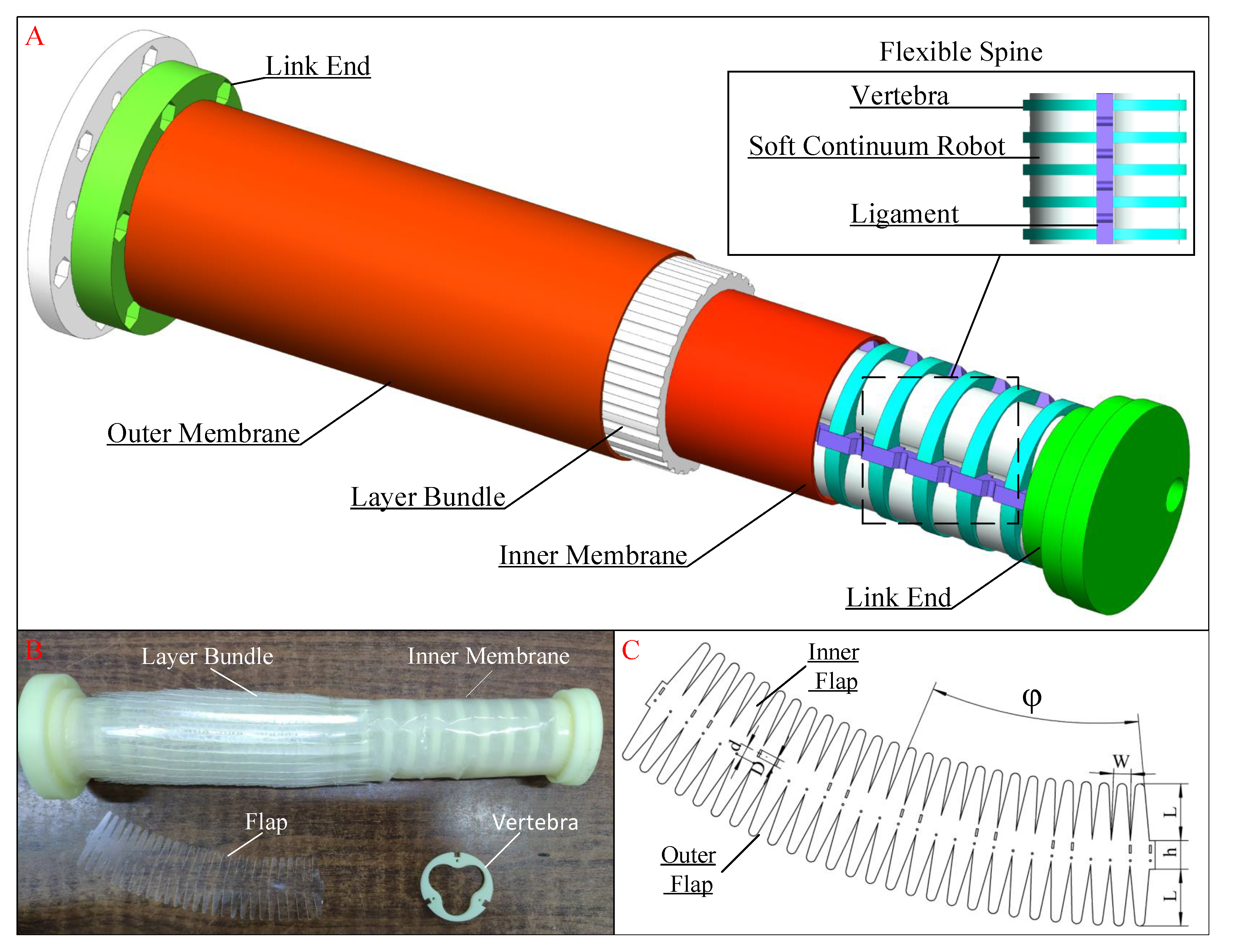
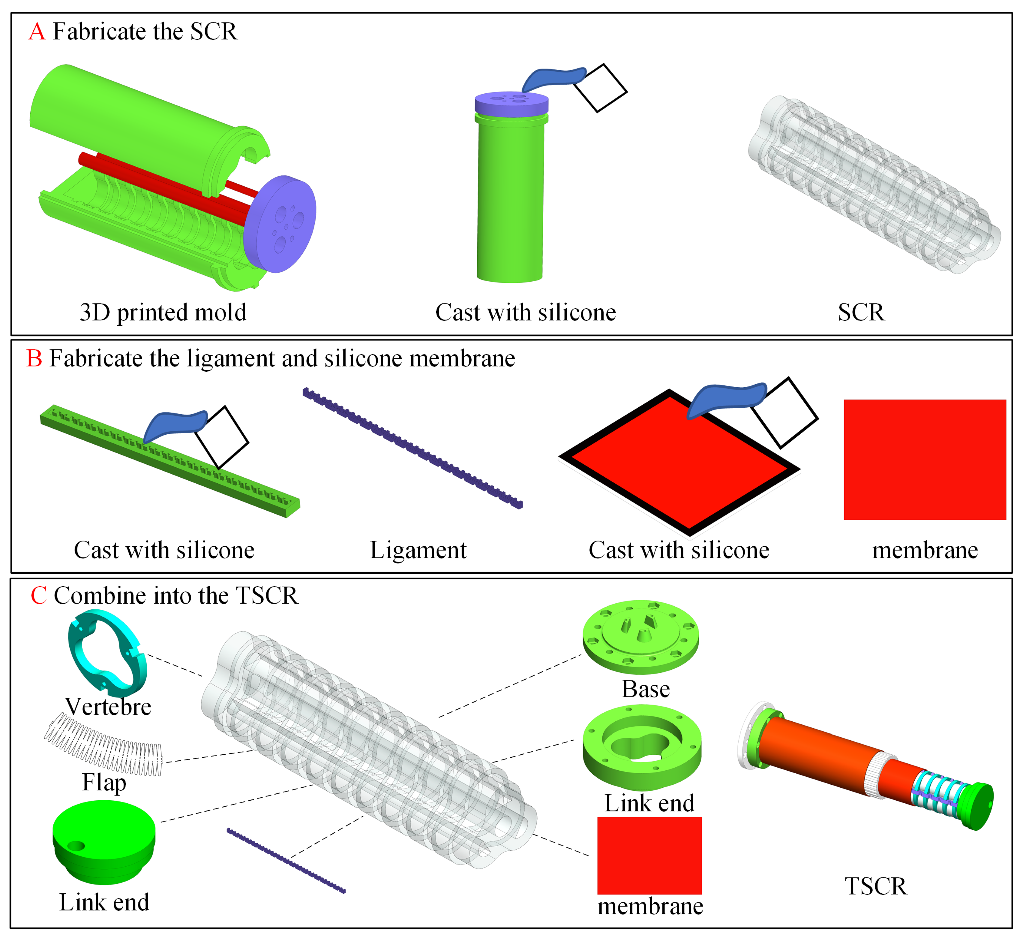
We combined a support structure and the SCR to propose a unique design, called the flexible drivable spine, which can reduce the undesired buckling of the layer jamming segment. The proposed mechanism was composed of several 3D-printed vertebrae made of acrylonitrile butadiene styrene (ABS) material and an SCR made of super-elastic material (Ecoflex 00-50; Smooth-on, Inc., Macungie, PA, USA), which has the advantage of being highly drivable and not impairing the layer jamming segment. Finally, we integrated the flexible drivable spine with the stiffening segment to obtain a novel tuneable-stiffness soft continuum robot (TSCR), as shown in Figure 1. Based on the design, the TSCR is endowed with bending shape control, as well as variable stiffness capabilities. In this paper, we present the design, performance, and experiments on the TSCR. The rest of the paper is organized as follows. Section 2 provides the details of the TSCR design, including the mechanical design and bio-inspired compliant spine mechanisms. Section 3 proposes an analytical model of a two-layer jamming structure, as well as extending predictions to many-layer jamming structures. Section 4 describes several experiments on the TSCR. Discussion and conclusions are presented in Section 5.

2. Robot Design

2.1. The Stiffening Segment Based on Layer Jamming

We employed existing layer jamming techniques to design the stiffening segment to construct the variable-stiffness SCR that can deform both aerodynamically and manually. The layer design featured the double-sided flap pattern proposed in [4], whose series parameters were the flap length L, the flap width W, the distance between the flaps on both sides h, and the central angle φ , as shown in Figure 1C. The flaps were connected and overlapped by nylon thread to form a conical tube through which the flexible drivable spine can pass. The layer property of the stiffening segment is to provide a frictional overlapping contact area, which depends on the length and width of the flaps, and the stiffening segment hardens through accumulated friction under compression. In addition, the number of layers overlapping each side of the flap is 6.5. The influence parameters on the maximum stiffness can be reflected by the maximum static friction force, which can be expressed as follows:
F = μ n P W L
where μ is the friction coefficient of the layer material, n is the number of contact surfaces between the layers at both ends, and P is the applied pressure. The stiffness of the stiffening segment can be tuned by pressure.
The layers were made of polyethylene terephthalate (PET) film, with thickness of 0.23 mm and a friction coefficient of 0.4, which is suitable for large-diameter stiffening segments as PET has high inherent rigidity. Moreover, a high-rigidity material ensures that the layers will not fail and buckle under the external force in the bending state. In order to construct the stiffening segment, the layers were joined together by a needle using 0.108 mm diameter strong nylon thread along the guide holes and slots. Moreover, the overall length and bending capacity of the stiffening segment depend on the length of the guide slot D and the center distance between hole and slot d. The length of the stiffening segment can be calculated as:
l = ( N 1 ) ( d ± D / 2 ) + h
and the bending angle can be expressed as
θ = ( N 1 ) arcsin D ϕ
where N is the number of the layers, ϕ is the diameter of the stiffening segment. The parameters of the stiffening segment can be seen in the Abbreviations and Parameters section, which also contains the parameters of the flap. According to Equation (2) and the Abbreviations and Parameters section, the adjustable length range of the stiffening segment can be calculated from 363.35 mm to 185.35 mm. The bending angle θ can reach 196 .
To activate the stiffening mechanism, the stiffening segment was wrapped in a sealed tubular membrane, which was made of hyperelastic material (Dragon Skin®10; Smooth-On) with a thickness of 0.3 mm, and then the layers of the segment were compressed together by vacuum. Based on the required parameters, a tubular sealing membrane was made by gluing the cut silicone sheet with glue, and was installed on the 3D-printed link ends with silicone-based adhesive (Sil-Poxy, Smooth-On). Furthermore, the tubular sealing membrane was connected to a vacuum pump through a 6mm PVC pipe on one of the TSCR ends to control the pressure inside the membrane.

2.2. The Flexible Drivable Spine

In order to prevent the potential risk of undesired buckling of the stiffening segment during bending, the flexible drivable spine was fabricated as inspired by the biological spine. It is an SCR with vertebrae that can maintain the constant diameter of the stiffening segment during operation. The spine consists of an SCR, ligaments, and 3D-printed rigid vertebrae, and is defined by the parameters of the gap between vertebrae G v , vertebra diameter D v , and vertebra height W v , as shown in Figure 1. To prevent the motion of the spine from impairing the overall bending performance of the stiffening segment, the ratio of rigid vertebrae to the overall length of the spine should be controlled at 50 % or lower to ensure that the spine can have the same or a greater range of tension and compression compared to the stiffening segment. The specifications of spine parameters are presented in the Abbreviations and Parameters section, from which the total length of vertebrae can be calculated as 76 mm. In addition, there are 10 mm rigid supports at both ends. The vertebrae were fitted into the grooves on the SCR in a linear array, and due to the special structural configuration of the SCR, there is no relative rotation with the vertebrae. In addition, a schematic diagram of TSCR fabrication is shown in Figure 2.
In this section, we give the design principles, key design parameters, functions of the stiffening segment, and the flexible drivable spine. In addition, we also introduce how the above two parts form the TSCR.

3. Minimal Model of Jamming Mechanism

To illustrate the relationship between the essential parameters and the jammed stiffness of the layer structure, a minimal mechanical model was constructed. There are two reasons for establishing this mechanical model. Fist, it is difficult to manufacture layer jamming specimens to test all possible parameter combinations in the design, so an analytical model helps to describe the general trend of stiffness changes as different parameters are adjusted. Second, the model can estimate suitable stiffness ranges of layer jamming to accomplish the design task, providing an efficient design tool.
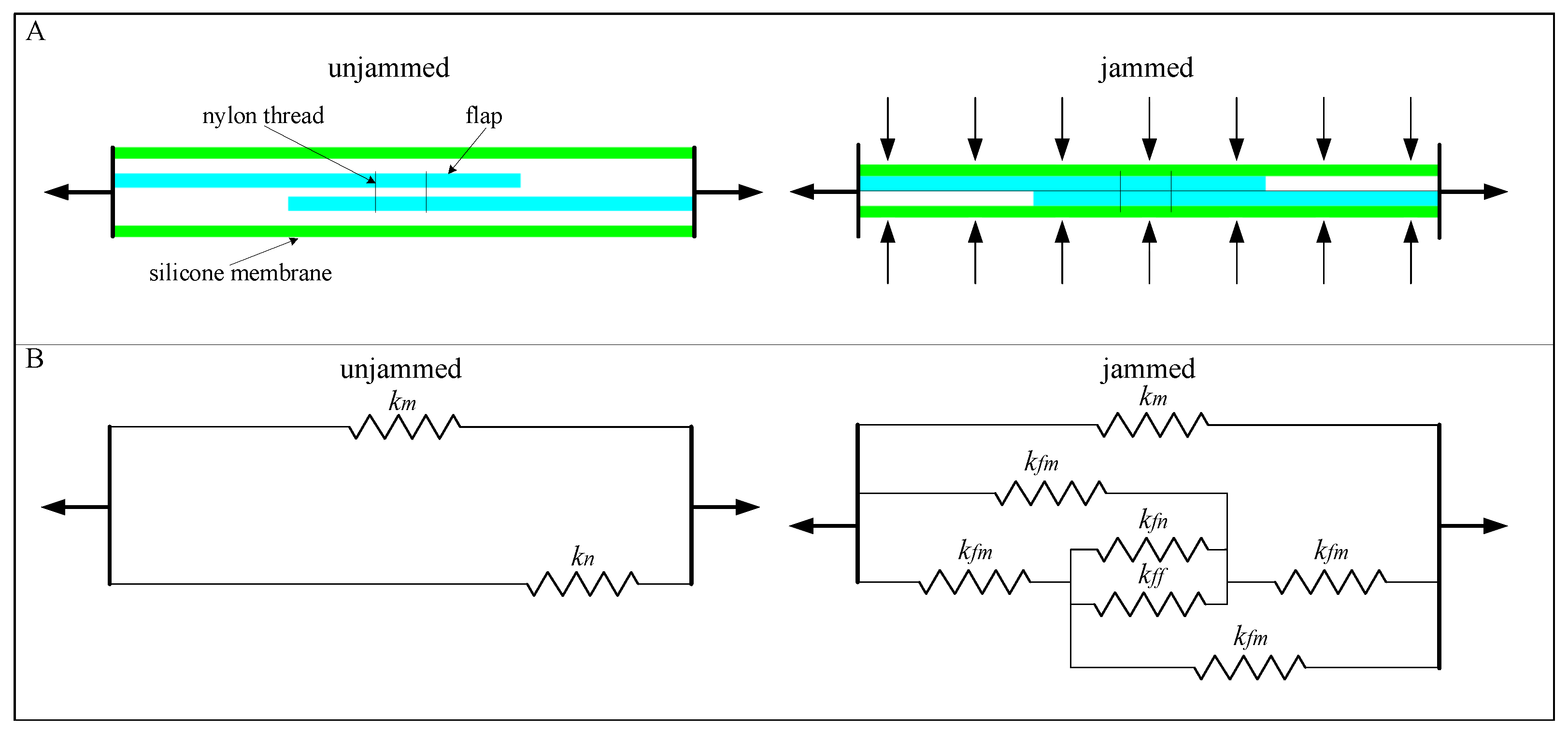
To simplify the analysis, the model only considers two layers of flaps and their interfaces, but at the end, we will further derive the model to include more flaps. Since the Young’s modulus of PET is much larger than that of the silicone membrane, we can assume that PET is inextensible. In the normal state, we assume that the initial friction between flaps is zero. Since PET is considered inextensible, the stiffness of the flaps in the tensile direction is only determined by the stiffness of the nylon thread ( k n ) used for stitching the flaps and the surrounding silicone membrane ( k m ), under the unjammed state. In the jammed state, the flaps are compressed together by external pressure ( Δ P ). The interfaces form between overlaps of flap–flap and flap–membrane. When pulled, shearing of these interfaces generates extra stiffness ( k f f and k f m , respectively). The parameters in the derivation refer to the schematic diagram in Figure 3.
We use the properties and dimensions of the nylon thread to define the stiffness parameters. The linear model for the tensile stiffness of a single nylon thread is as follows:
k n = E n A n L n
where E n is the Young’s modulus of the nylon thread, L n is the total length of the nylon thread, A n is the cross-section area of the nylon thread ( A n = π D n , circular-shaped cross-section, D n is the diameter of nylon thread). The tensile stiffness of a silicone membrane ( k m ) can also be established as a linear model as follows:
k m = E m A m L m
where E m is the Young’s modulus of the silicone membrane, L m is the total length of the silicone membrane, A m is the cross-section area of the silicone membrane ( A m = A m i + A m o , A m i is the cross-sectional area of the inner membrane, and A m o is the cross-sectional area of the outer membrane.). The shear stiffness of the flap–silicone membrane interface can be expressed as:
k f m = β G A f m t
where G = E m 1 + ϑ is the shear modulus of silicone ( ϑ is the Poisson ratio), A f m is the area between the flap and silicone membrane ( A f m = L f m d ), t is the thickness of the flap–silicone membrane, and β is a parameter to indicate that the contact area between flap and silicone membrane is not all under shear β 1 .
The mechanical properties of shear interfaces can be divided into a linear region and nonlinear region. In the linear region, it is linear with the displacement until the maximum force is reached. The nonlinear relationship is caused by slip. Therefore, the jammed state of the layer structure also can be divided into three regimes: pre-slip regime, transition regime, and full-slip regime.
In practice, the stiffening segment is subjected to a cantilevered condition, so the Euler–Bernoulli beam theory was employed for analysis. Since the overlapping part of the flaps can be approximated as an isosceles trapezoid, the area of the first moment of the cross-section of the top layer with respect to the interface between the layers can be expressed as J = 2 W L W x H 2 4 L . Furthermore, the area of the second moment of the cross-section can be expressed as I = 2 W L W x H 3 6 L . Specifically, the effective stiffness of the layer structure can be defined as the relationship between the distributed load and the deflection at the free end ( k = ω w x = L ).
Substituting I provided into the standard result derived from beam theory, we can obtain the equivalent expression for the pre-slip regime as follows:
w p r e x = 6 ω L 3 8 E W * H 3 x 2 + 6 ω L 2 12 E W * H 3 x 3 6 ω L 48 E W * H 3 x 4
where w is the transverse deflection of the layer structure within the interface, ω is the distributed load, H is the thickness of the flap, W * is 2 W L W x (W and L are the length and width of the flap, respectively). Substituting Equation (7) into the definition of stiffness, the effective shear stiffness of the flap–flap interface in the pre-slip regime is illustrated as:
k f f - p r e = α E W H 3 L 4
where α is the effective contact ratio of flaps (a parameter taking incomplete contact into account). Moreover, substituting I and J into the standard result derived from beam theory, the equivalent expression for the transition regime can be written as:
w t r a n ( x ) = w p r e x 81 ω L 5 128 E W * H 3 + 27 μ p L 3 16 E H 2 27 μ p L W * 16 E ω H + 3 μ p 3 W * 2 4 E ω 2 L μ p 4 W * 3 H 8 E ω 3 L 3
Substituting Equation (9) into the definition of stiffness, the effective shear stiffness of the flap–flap interface in the transition regime is illustrated as:
k f f - t r a n = 128 E W H 3 ω 4 48 μ p W H 4 192 ω L μ P W H 3 + 216 μ P ω W L H 2 129 ω 4 L 5
We modeled collections of flaps in parallel within the inner membrane and the outer membrane. For the system of the stiffening segment in the unjammed state, the only stiffness sources are k n and k m . Thus, the unjammed stiffness can be written as:
k u = N n k n + k m
where N n is the number of nylon threads in the stiffening segment. None of the various properties of the silicone membrane are varied; thus, k m is a constant.
In the jammed state, stiffness is contributed from all interfaces as well as the silicone membrane, flaps, and nylon (see Figure 3, right). The total stiffness can be derived from a combination of series and parallel stiffness. For a two-layer stiffening segment system, we can obtain the following equation:
k j , N = 2 = k f m 2 + k f m k f n + k f f 1 + k f n + k f f + k m
Since k f f and k f m are much larger compared to k f n , they dominate the stiffness of the system. By eliminating the k f n term, we can simplify Equation (12) to:
k j , N = 2 = k f m 2 + k f m k f f 1 + k f f + k m
To illustrate jamming layers with N > 2 , we observe that for each additional layer, each additional flap increases the number of flap–flap interfaces by one. Since these interfaces are parallel to each other and arrayed along the axis, the k f f term can directly multiply the number of interfaces, z = N 1 .
k j , N > 2 = k f m 2 + k f m z k f f 1 + k f f + k m
By observing that k f f and k f m are approximately equal in a certain pressure range, we can further simplify Equation (14) as:
k j = 1 + z z k f f + k m
According to the actual situation, the actual values will be used to replace z in the above formula, which can clarify an overall trend. In other words, the stiffness of the flap increases with the increase in the unit length, which is also fully proven by the experimental results.
In the jammed state, the stiffness of the model has been presented before slip. The nonlinear case occurs when the shear force in the interface exceeds the maximum static friction that the interface between adjacent flaps can withstand. The maximum static friction can be written as:
F f m a x Δ P = μ Δ P A f f
where μ is the coefficient of static friction, A f f is the area of shear between flap and flap ( A f f = W L ). After slip occurs, the equivalent expression for the full-slip regime can be written as:
w s l i p x = μ P L 3 H 2 E 3 ω L 2 E W H 3 x 2 2 ω L E W H 3 3 μ P E H 2 x 3 ω 2 E W H 3 x 4
Substituting Equation (17) into the definition of stiffness, the effective shear stiffness of the flap–flap interface in the full-slip regime decreases to:
k f f s l i p = 2 E W H 3 3 L 4
In addition, this stiffness is equal to the effective stiffness of the two-layer structure with no vacuum applied.
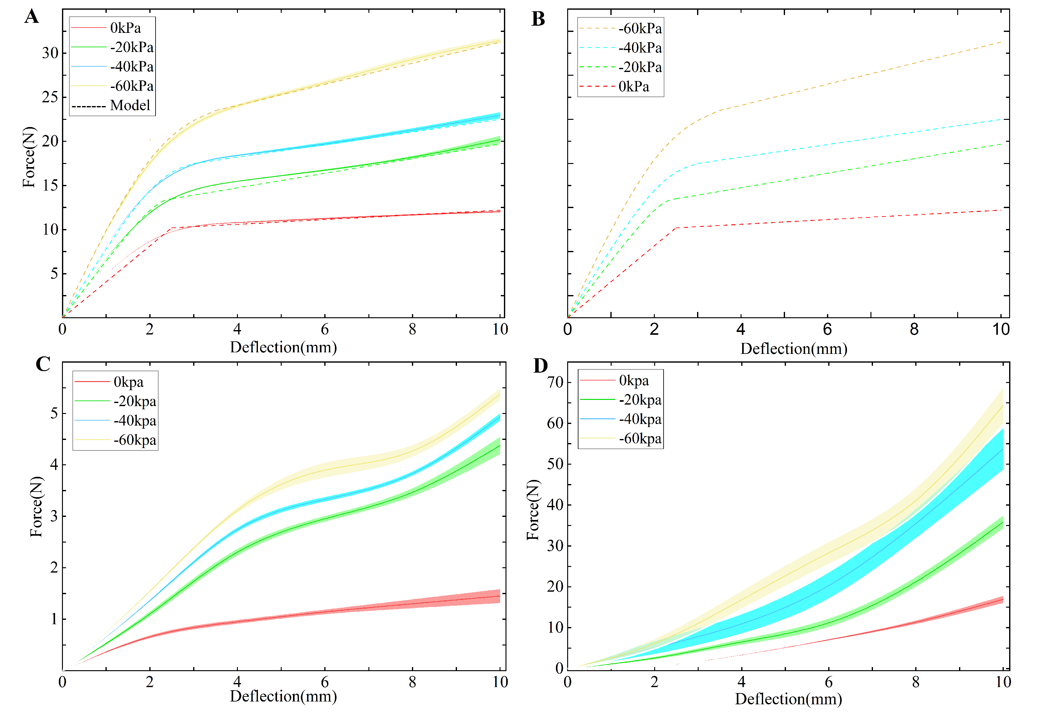
All the parameters in the minimal layer jamming model presented in the Abbreviations and Parameters section were used to generate the analytical prediction (dashed line) in Figure 4A. The values of parameters, including α and β , were determined by comparing the similarity between the data and model.
In this section, we construct a minimal mechanical model to illustrate the relationship between essential parameters and the jammed stiffness of the layer structure. The model covers the jammed and unjammed states of the layer structure. Furthermore, the jammed state of the layer structure also can be divided into three regimes: pre-slip regime, transition regime, and full-slip regime. In addition, we also consider the case in which the flaps are not fully in contact.

4. Results and Experimental Setup

Based on the analysis results, the constructed stiffening segment prototype was assembled to the pneumatic the flexible drivable spine and evaluated to demonstrate its applicability. In addition, the stiffness improvement of the flexible spine with the stiffening segment was evaluated.
Having quantified the effect of the essential design parameters on the jamming layer’s stiffness, we evaluated the TSCR in three ways. First, to evaluate stiffness and flexibility of the TSCR, we conducted the lateral deflecting experiments at 0 and 90 configurations, as well as the axial compression experiments. Second, in order to evaluate the ability of TSCR to resist abnormal deformation in applications, we manually bent the TSCR from 0 to 180 in 45 
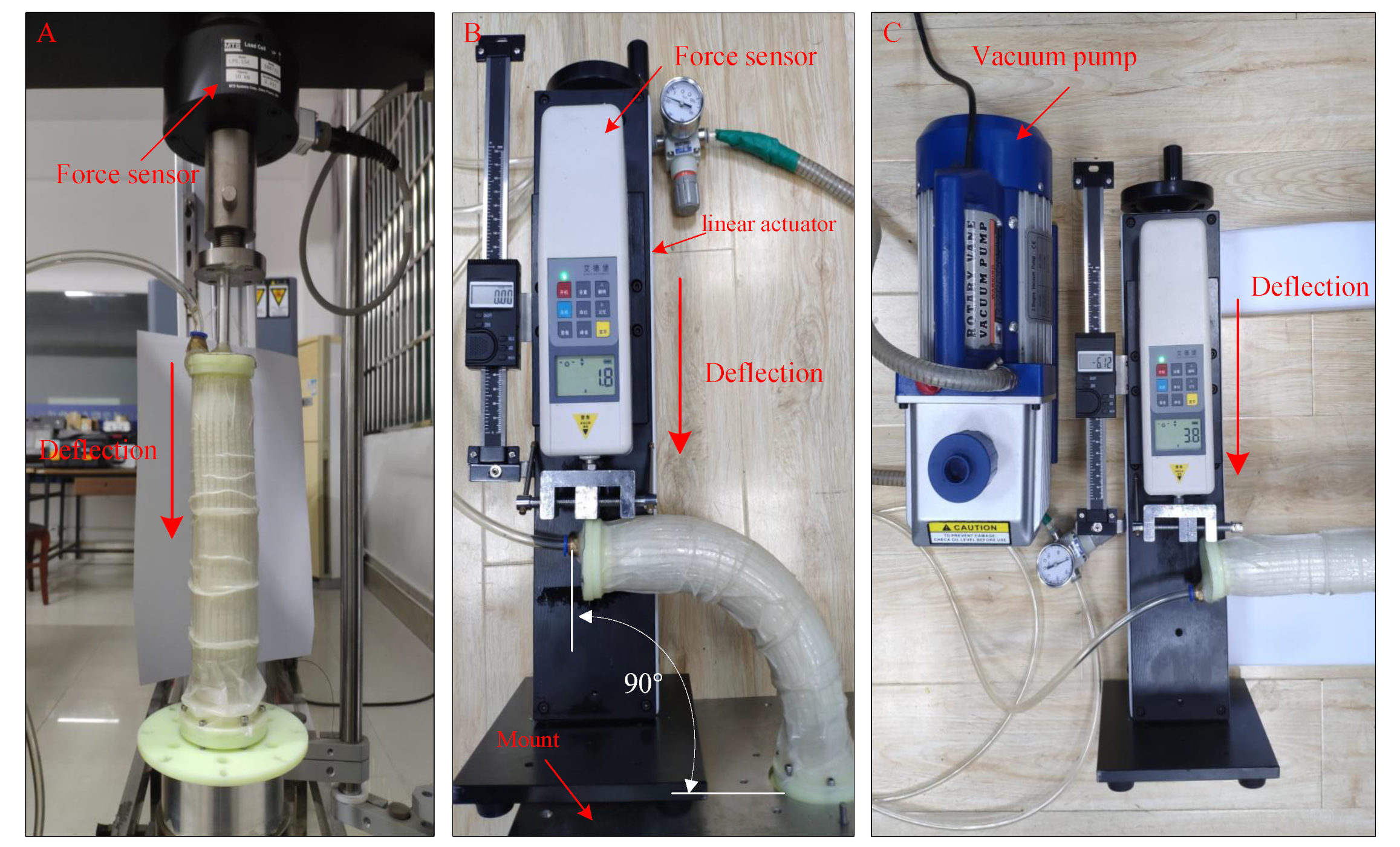
increments. The ratio of change in the diameter of the TSCR center at each incremental point can be used as an evaluation criterion. Third, to evaluate the actual performance of the TSCR, we conducted grasping and loading experiments. The experimental platform configuration is shown in Figure 5. It is composed a linear actuator and a force sensor (WD-500, Aidebao Co, Wenzhou, China) mounted on an axially moving slide. The vacuum pressure applied to the stiffening segment was from 0 kPa to −60 kPa with a gradient of −20 kPa (VP 280, 2-stage vacuum pump).

4.1. Evaluation of the TSCR’s Stiffness and Flexibility

In the experiments, the tested TSCR was mounted on an aluminum plate with a fixed position relative to the linear actuator. The initial relative position of the force sensor to the TSCR is that the force sensor touches the TSCR but no force is detected, and the displacement is 0 mm. During the experiment, the force sensor pushes the TSCR along the axial direction to deflect the required distance. For the lateral deflection experiment, the tested distances for each different position include 2 cm, 4 cm, 8 cm, and 10 cm (Figure 5B,C). For the compression experiment, the axial compression distance is also from 0 cm to 10 cm with a gradient of 2 cm (Figure 5A). We performed 50 cycles of various test protocols in both the unjammed and jammed states. For each test, the required force for the desired deflection needed to be recorded separately.
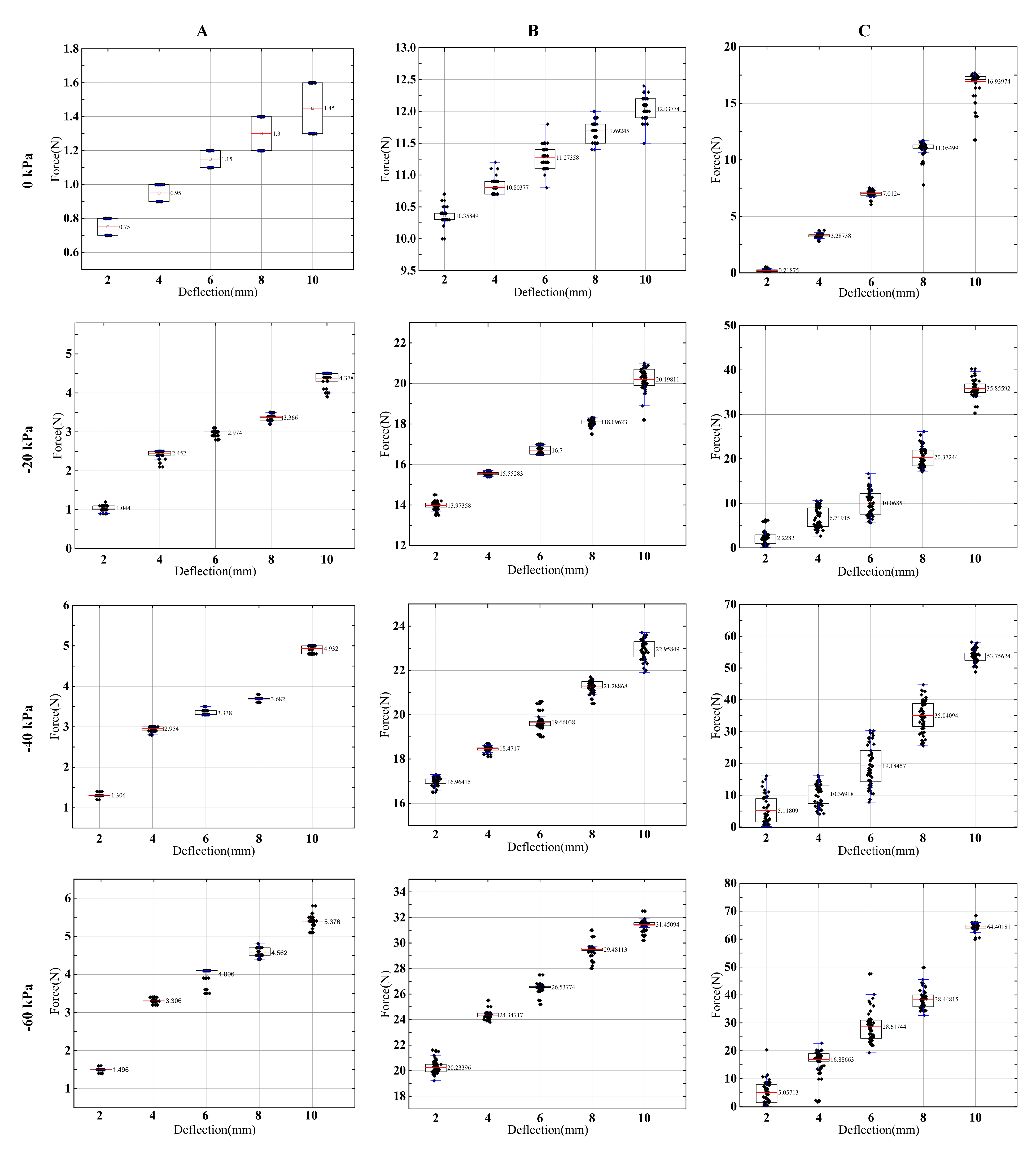
Here, we adopt a boxplot, which displays the minimum, median, and maximum, the first and third quartile, along with outliers of peak force, for the axial compression experiments as well as lateral deflecting experiments at 0 and 90 configurations, recorded in the measurement; results are summarized in Figure 6. The force–deflection diagrams for the axial compression experiments as well as lateral deflecting experiments at 0 and 90 configurations are shown in Figure 4.
From the results of the lateral deflection experiment in Figure 6, we can observe that the TSCR reached a much higher stiffness in the jammed state, which is up to 60 times higher compared with the initial TSCR. In the 0° configuration, the maximum average deflection force and average axial compression force can reach 5 N and 64 N, respectively. In the 90° configuration, the maximum average deflection force can reach 31 N. Due to the existence of the backbone, the TSCR can maintain high stiffness, instead of decreasing stiffness caused by buckling under the 90° configuration.
It can be seen from Figure 4 that the stiffening segment based on layer jamming bends under compressive force, and the stiffening segment exhibits unstable behavior due to the sudden slip between the flaps. In the unjammed state, the force–displacements of the TSCR are linear, which indicates higher compression for higher stiffness. In Figure 4A, except for some points, the minimum coefficient of determination ( R 2 ) between experimental and model data is 0.9525. Factors that cause discrepancies between the model and the collected results are errors generated during testing, uneven negative pressure distribution, non-standard flap overlap, and small gas leaks. In Figure 4A, the slope of the curve should reflect the change in stiffness. The area where the stiffness changes significantly is located in the transition regime, and the stiffness is a constant in the pre-slip and full-slip regions. In addition, at 60 kPa, the overlap rate between flaps is much higher than at 40 kPa. Therefore, the curve interval between −60 kpa and −40 kpa in Figure 4A is larger than the curve interval between 20 kPa and 40 kPa. Furthermore, the finite element results in Figure 4B are in good agreement with the analytical model results in Figure 4A.
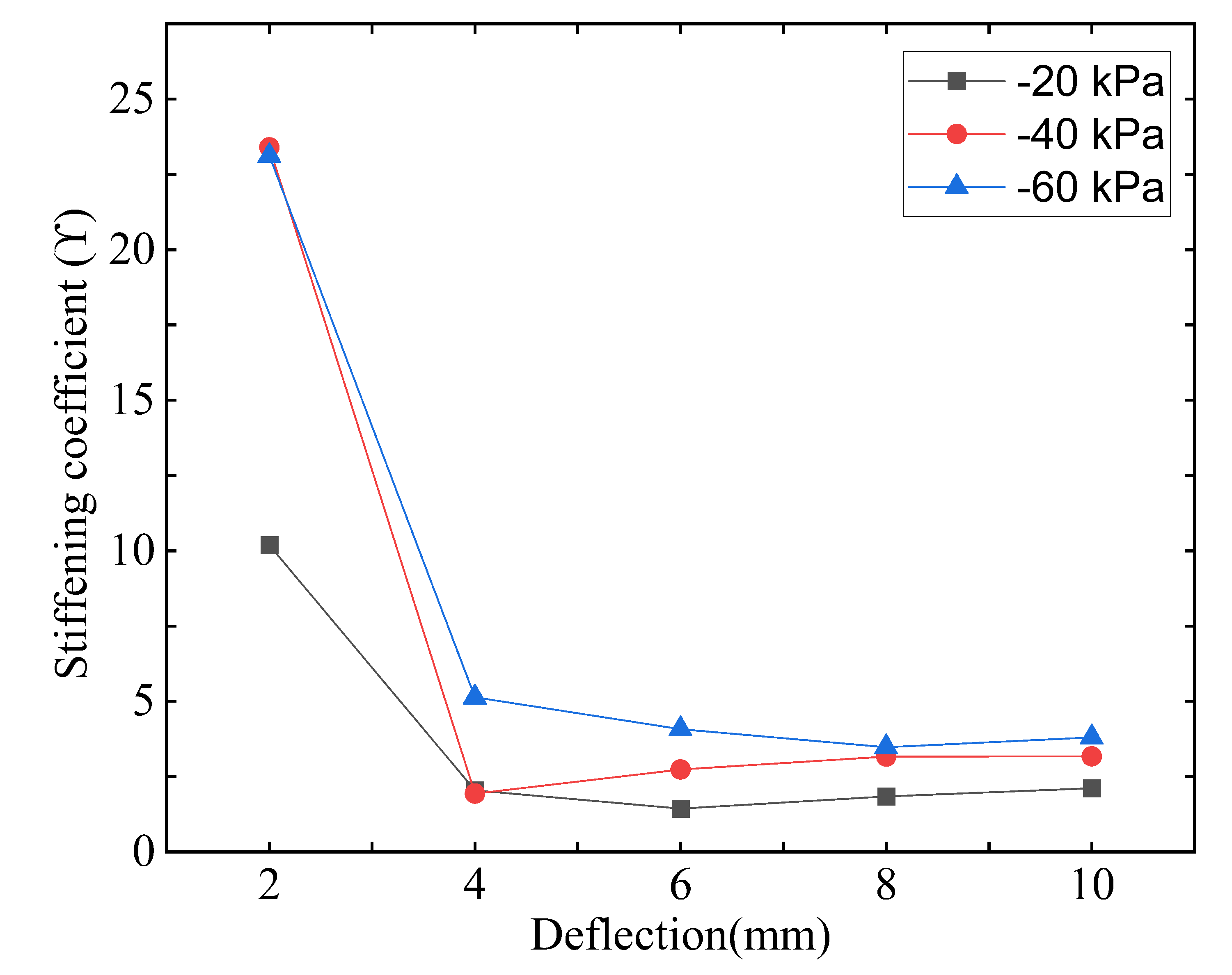
Noticeably, the stiffness increases dramatically in the high-stiffness region, because of the increase in the overlapping area. This also illustrates that the stiffness is positively correlated with the amount of axial compression within a certain range. In order to quantify the stiffening effect of the stiffening segment on the TSCR, a stiffening coefficient γ was proposed as follows:
γ = F ¯ j a m m e d / F ¯ u n j a m m e d
where F ¯ represents the average of forces measured in each type of axial compression experiment.
Figure 7 shows the stiffness coefficients for various amounts of axial compression. Compared with the soft continuum robot, the TSCR has comparable stiffness in the unjammed state, which can be indicated by the sudden change in stiffening coefficient in Figure 7. It is clear that the stiffening coefficient and the amount of axial compression within a certain range are positively correlated.
According to the results of these experiments, we can achieve a good balance between stiffness and compliance with the stiffening segment based on layer jamming. Although the stiffening segment is limited to a certain compliance, the stiffness improvement of the SCR is very significant. Sufficient repeatable stiffness of the TSCR was also observed in the examination, and its bending flexibility was not compromised. In addition, at the limit of the length of the stiffening segment, the nylon thread restricts the movement of the flaps. Furthermore, when compressed, the TSCR also showed a tendency to buckle. However, once the vacuum was released, the buckling deformation was reversible.

4.2. Evaluation of the TSCR Central Diameter

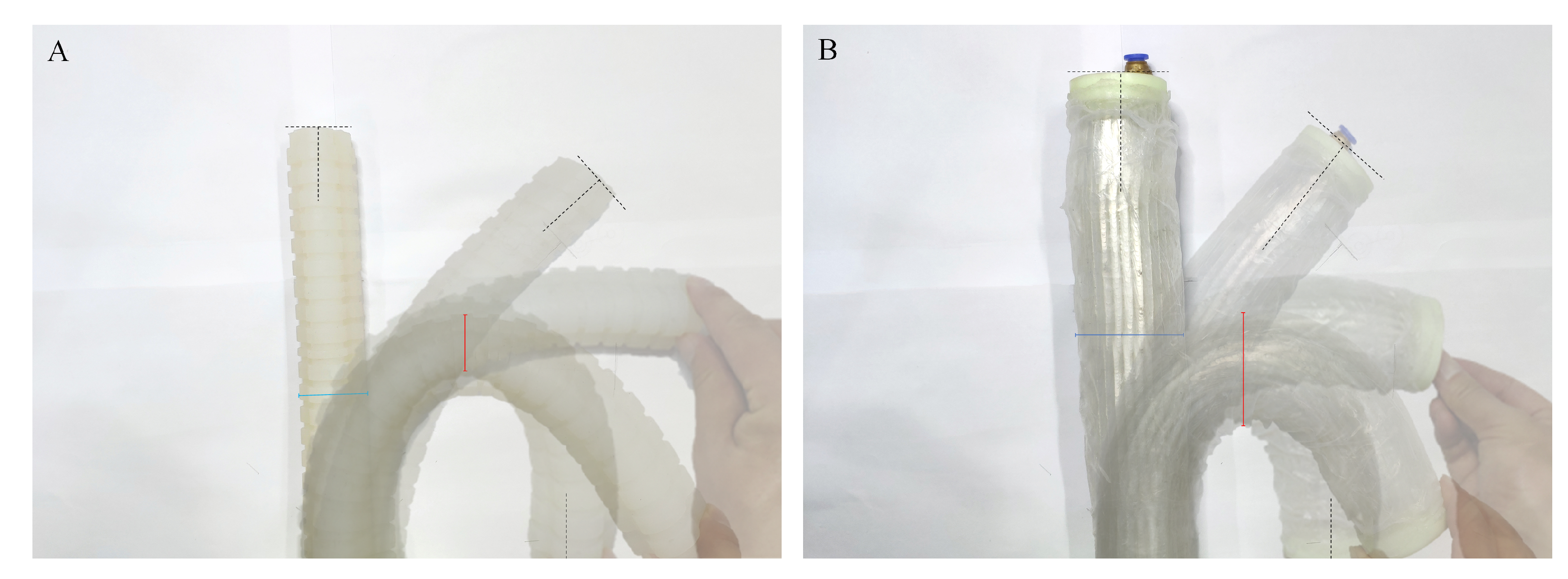
The constant diameter of the soft continuum robot facilitates simplified theoretical analysis, precise position control, and the avoidance of buckling, all of which are important for SCR operation. In particular, under the large structural bending state, the central diameter change is a critical consideration.
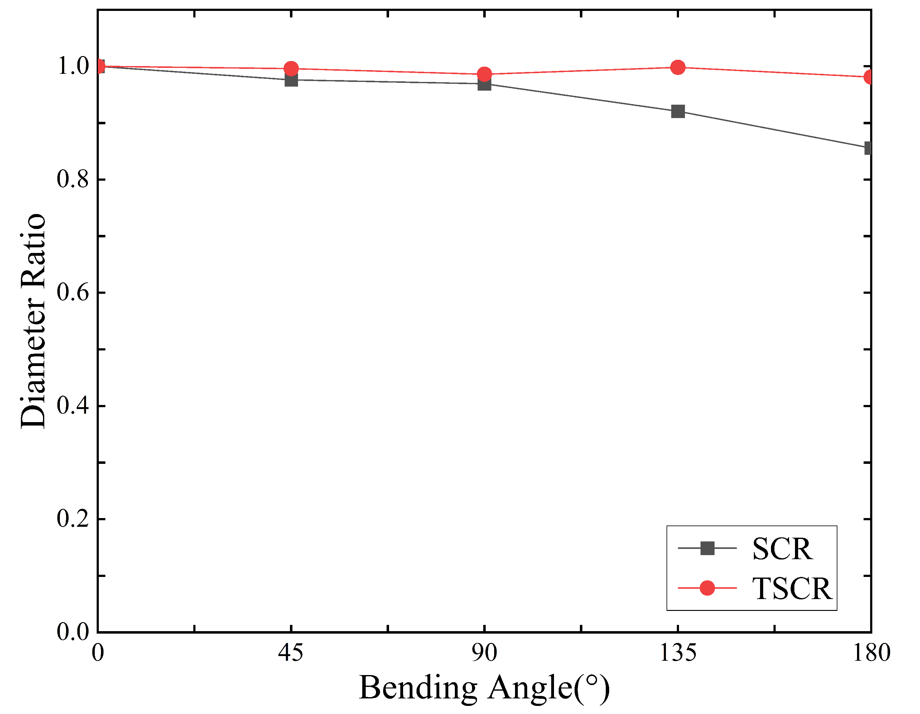
Figure 8 shows the effect of the bending angle configuration on the TSCR and SCR diameter. The ratio of the diameter of the TSCR and SCR configurations at each angle to the diameter of the 0° configuration (highlighted green, and highlighted red in 180° configuration on Figure 8) was used as a quantification factor. Then, in order to indicate the relationship between the diameter ratio and the bending angle, the diameter ratio and the bending angle were plotted correspondingly, as shown in Figure 9. The SCR exhibited buckling in a 0.856 ratio at 180°. The TSCR presented the highest diameter ratio in 0.981 at 180°. Therefore, TSCR is significantly better than SCR in center diameter retention. This situation is very beneficial for subsequent control.
The above experimental results show that the stiffening segment based on layer jamming endows the TSCR with a good balance between compliance and stiffness. Although the axial load capacity of the TSCR is significantly higher than that of other configurations, the minimum load that other configurations can withstand also reaches 5 N. In addition, after repeated testing, the TSCR has shown sufficient repeatable stiffness.

4.3. Evaluation of TSCR by Comparing with Different Actuators

In order to further illustrate the availability of the TSCR, we compare it with representative different actuators from five aspects, such as bending angle, pressure, force, weight, and cost.
From Table 1, we can see that the pressure of most actuators has only a single value, indicating that they can only achieve stiffness changes or other functions. In terms of bending angle and force, the TSCR also has obvious advantages. The continuum robot [28] has the closest performance to the TSCR. However, since the robot is tendon-driven, it cannot extend itself as with TSCR and has an inherent risk of buckling.
In this section, we introduce the results of experimental evaluations about the TSCR’s stiffness and flexibility. Experiments show that the stiffening segment can indeed greatly improve the stiffness of the SCR. Furthermore, the experimental results are in good agreement with the model. In addition, the experimental results also show that central diameter of the TSCR is well maintained, indicating that the vertebrae can indeed prevent the buckling of the stiffening segment during operation. In addition, the performance of the TSCR is significantly improved compared to other representative actuators. All parameters in this section are shown in the Abbreviations and Parameters section.

5. Conclusions

In this paper, we proposed a stiffness-tuneable segment for soft continuum robots with vertebrae to improve the stiffness in certain desired configurations. The potential undesired buckling of the stiffness-tuneable segment during operation can be prevented by the vertebrae on the SCR. We also have derived an analytical model for jamming structures over three major phases of deformation and effective stiffness, and extracted critical design parameters. We also conducted several experimental evaluations, which illustrated that the effective stiffness improvement by 15× to 60× compared to the initial TSCR could be achieved. In addition, the factors that cause a slight deviation between the jamming model and the experimental results may come from small damage during the production of the silicone membrane, irregular flap stacking, and uneven vacuum distribution.
In future work, miniaturization of the TSCR should be considered for interventional medicine, while the current TSCR can be used for exoskeleton rehabilitation robots. In order to obtain a better compromise between rigidity and flexibility, we can design flaps based on the principle of bionics, and the bionic objects can be scaled objects such as pangolins and fish. In addition, the weaving patterns and materials of flaps can also be used as further research directions. When building the TSCR controller, it is necessary to quantify the hysteresis effect of the loading and unloading of the stiffening segment.
To conclude, we illustrate the mechanics of layer jamming, provide an efficient design tool for jamming structures, and provide references for creating variable robots and mechanisms.

Author Contributions

Conceptualization, Z.L. and L.X.; methodology, Z.L.; software, X.L.; validation, Z.L., L.X. and J.L.; formal analysis, Z.L.; investigation, L.X.; resources, J.L.; data curation, X.L.; writing—original draft preparation, Z.L.; writing—review and editing, L.X.; visualization, X.L.; supervision, L.X.; project administration, L.X. All authors have read and agreed to the published version of the manuscript.

Funding

This research was funded by a Jiangsu Special Project for Frontier Leading Base Technology, grant number BK20192004; Suzhou Key Industrial Technology Innovation Forward-Looking Application Research Project, grant number SYG202143; Fundamental Research Funds for Central Universities, grant number B220201025; Changzhou Key Research and Development Projects, grant number CJ20210040, and the General Project of the Natural Science Foundation of Colleges and Universities of Jiangsu Province, grant number 21KJB460006.

Institutional Review Board Statement

Not applicable.

Informed Consent Statement

Not applicable.

Data Availability Statement

The data presented in this study are available on request from the authors.

Acknowledgments

The authors thank Hefei Institutes of Physical Science, Chinese Academy of Sciences, for the experimental setup.

Conflicts of Interest

The authors declare no conflict of interest.

Abbreviations and Parameters

The following abbreviations and parameters are used in this manuscript:
Abbreviations
SCRSoft continuum robot
TSCRTuneable-stiffness soft continuum robot
ParametersDescription
WWidth of flap
LLength of flap
DLength of the guide slot
dCenter distance between hole and slot
ϕ Diameter of stiffening segment
hDistance between the flaps on both sides
NNo. of layers
nNo. of layers overlapping each side
μ Friction coefficient
lThe length of stiffening segment
θ The bending angle of stiffening segment
D v Vertebra diameter
W v Vertebra height
G v Gap between vertebrae
N v No. of vertebrae
L s Initial length of SCR
L n Total length of the nylon thread
k n The stiffness of nylon thread
E n Young’s modulus of nylon thread
A n Cross-section area of nylon thread
D n Diameter of nylon thread
Δ P Diameter of nylon thread
k m The tensile stiffness of silicone membrane
E m Young’s modulus of membrane
L m Total length of the silicone membrane
A m Cross-section area of the silicone membrane
A m o Cross-sectional area of outer membrane
A m i Cross-sectional area of inter membrane
EYoung’s modulus of PET
GShear modulus of silicone
ν Poisson’s ratio of membrane
k f m Shear stiffness of the flap–silicone membrane interface
A f m         Area between flap and membrane
t        Thickness of flap–silicone membrane
β         Ratio of contact between flap and membrane
k f f         Shear stiffness of the flap–flap interface
A f f         Area between flap and flap
k f f - p r e         Shear stiffness of the flap–flap interface in pre-slip regime
k f f - t r a n         Shear stiffness of the flap–flap interface in transition regime
k f f - s l i p         Shear stiffness of the flap–flap interface in full-slip regime
W p r e         Transverse deflection of the layer structure within the interface in pre-slip regime
W t r a n         Transverse deflection of the layer structure within the interface in transition regime
W s l i p         Transverse deflection of the layer structure within the interface in full-slip regime
α         Effective contact ratio of flaps
ω         Distributed load
H        Thickness of the flap
γ         Stiffening coefficient
F ¯ j a m m e d         Average of force at the jammed state
F ¯ u n j a m m e d         Average of force at the unjammed state

References

  1. Tur, J.M.M.; Garthwaite, W. Robotic devices for water main in-pipe inspection: A survey. J. Field Robot. 2010, 4, 491–508. [Google Scholar]
  2. Deimel, R.; Brock, O. A novel type of compliant and underactuated robotic hand for dexterous grasping. Int. J. Robot. Res. 2016, 35, 161–185. [Google Scholar] [CrossRef] [Green Version]
  3. Cheng, N.; Amend, J.; Farrell, T.; Latour, D.; Martinez, C.; Johansson, J.; McNicoll, A.; Wartenberg, M.; Naseef, S.; Hanson, W.; et al. Prosthetic jamming terminal device: A case study of untethered soft robotics. Soft Robot. 2016, 3, 205–212. [Google Scholar] [CrossRef] [PubMed]
  4. Degani, A.; Choset, H.; Wolf, A.; Ota, T.; Zenati, M.A. Percutaneous intrapericardial interventions using a highly articulated robotic probe. In Proceedings of the First IEEE/RAS-EMBS International Conference on Biomedical Robotics and Biomechatronics, 2006, BioRob 2006, Pisa, Italy, 20–22 February 2006; IEEE: Piscataway, NJ, USA, 2006; pp. 7–12. [Google Scholar]
  5. Burgner-Kahrs, J.; Rucker, D.C.; Choset, H. Continuum robots for medical applications: A survey. IEEE Trans. Robot. 2015, 31, 1261–1280. [Google Scholar] [CrossRef]
  6. Kolachalama, S.; Lakshmanan, S. Continuum robots for manipulation applications: A survey. J. Robot. 2020, 2020, 4187048. [Google Scholar] [CrossRef]
  7. Pettersson, A.; Davis, S.; Gray, J.O.; Dodd, T.J.; Ohlsson, T. Design of a magnetorheological robot gripper for handling of delicate food products with varying shapes. J. Food Eng. 2010, 98, 332–338. [Google Scholar] [CrossRef]
  8. Jaeger, H.M. Celebrating soft matter’s 10th anniversary: Toward jamming by design. Soft Matter 2015, 11, 12–27. [Google Scholar] [CrossRef]
  9. Loeve, A.J.; Bosma, J.H.; Breedveld, P.; Dodou, D.; Dankelman, J. Polymer rigidity control for endoscopic shaft-guide ‘Plastolock’—A feasibility study. J. Med. Devices 2010, 4, 045001. [Google Scholar] [CrossRef] [Green Version]
  10. Lathrop, E.; Adibnazari, I.; Gravish, N.; Tolley, M.T. Shear strengthened granular jamming feet for improved performance over natural terrain. In Proceedings of the 2020 3rd IEEE International Conference on Soft Robotics (RoboSoft), New Haven, CT, USA, 15 May–15 July 2020; IEEE: Piscataway, NJ, USA, 2020; pp. 388–393. [Google Scholar]
  11. Shintake, J.; Schubert, B.; Rosset, S.; Shea, H.; Floreano, D. Variable stiffness actuator for soft robotics using dielectric elastomer and low-melting-point alloy. In Proceedings of the 2015 IEEE/RSJ International Conference on Intelligent Robots and Systems (IROS), Hamburg, Germany, 28 September–2 October 2015; IEEE: Piscataway, NJ, USA, 2015; pp. 1097–1102. [Google Scholar]
  12. Nasab, A.M.; Sabzehzar, A.; Tatari, M.; Majidi, C.; Shan, W. A soft gripper with rigidity tunable elastomer strips as ligaments. Soft Robot. 2017, 4, 411–420. [Google Scholar] [CrossRef]
  13. Yang, B.; Lin, Q. A latchable microvalve using phase change of paraffin wax. Sens. Actuators A Phys. 2007, 134, 194–200. [Google Scholar] [CrossRef]
  14. Wang, L.; Yang, Y.; Chen, Y.; Majidi, C.; Iida, F.; Askounis, E.; Pei, Q. Controllable and reversible tuning of material rigidity for robot applications. Mater. Today 2018, 21, 563–576. [Google Scholar] [CrossRef]
  15. Jiang, A.; Ranzani, T.; Gerboni, G.; Lekstutyte, L.; Althoefer, K.; Dasgupta, P.; Nanayakkara, T. Robotic granular jamming: Does the membrane matter? Soft Robot. 2014, 1, 192–201. [Google Scholar] [CrossRef]
  16. Li, Y.; Chen, Y.; Yang, Y.; Wei, Y. Passive particle jamming and its stiffening of soft robotic grippers. IEEE Trans. Robot. 2017, 33, 446–455. [Google Scholar] [CrossRef]
  17. Zhou, J.; Chen, Y.; Hu, Y.; Wang, Z.; Li, Y.; Gu, G.; Liu, Y. Adaptive variable stiffness particle phalange for robust and durable robotic grasping. Soft Robot. 2020, 7, 743–757. [Google Scholar] [CrossRef]
  18. Cianchetti, M.; Ranzani, T.; Gerboni, G.; Nanayakkara, T.; Althoefer, K.; Dasgupta, P.; Menciassi, A. Soft robotics technologies to address shortcomings in today’s minimally invasive surgery: The STIFF-FLOP approach. Soft Robot. 2014, 1, 122–131. [Google Scholar] [CrossRef]
  19. Choi, J.; Lee, D.Y.; Eo, J.H.; Park, Y.J.; Cho, K.J. Tendon-driven jamming mechanism for configurable variable stiffness. Soft Robot. 2021, 8, 109–118. [Google Scholar] [CrossRef]
  20. Keller, S.; Jaeger, H.M. Aleatory architectures. Granul. Matter 2016, 18, 29. [Google Scholar] [CrossRef] [Green Version]
  21. Jadhav, S.; Majit, M.R.A.; Shih, B.; Schulze, J.P.; Tolley, M.T. Variable stiffness devices using fiber jamming for application in soft robotics and wearable haptics. Soft Robot. 2022, 9, 173–186. [Google Scholar] [CrossRef]
  22. Narang, Y.S.; Vlassak, J.J.; Howe, R.D. Mechanically versatile soft machines through laminar jamming. Adv. Funct. Mater. 2018, 28, 1707136. [Google Scholar] [CrossRef] [Green Version]
  23. Narang, Y.S.; Degirmenci, A.; Vlassak, J.J.; Howe, R.D. Transforming the dynamic response of robotic structures and systems through laminar jamming. IEEE Robot. Autom. Lett. 2017, 3, 688–695. [Google Scholar] [CrossRef]
  24. Santiago, J.L.C.; Godage, I.S.; Gonthina, P.; Walker, I.D. Soft robots and kangaroo tails: Modulating compliance in continuum structures through mechanical layer jamming. Soft Robot. 2016, 3, 54–63. [Google Scholar] [CrossRef]
  25. Ou, J.; Yao, L.; Tauber, D.; Steimle, J.; Niiyama, R.; Ishii, H. jamSheets: Thin interfaces with tunable stiffness enabled by layer jamming. In Proceedings of the 8th International Conference on Tangible, Embedded and Embodied Interaction, Munich, Germany, 16–19 February 2014; pp. 65–72. [Google Scholar]
  26. Kim, Y.J.; Cheng, S.; Kim, S.; Iagnemma, K. Design of a tubular snake-like manipulator with stiffening capability by layer jamming. In Proceedings of the 2012 IEEE/RSJ International Conference on Intelligent Robots and Systems, Vilamoura-Algarve, Portugal, 7–12 October 2012; IEEE: Piscataway, NJ, USA, 2012; pp. 4251–4256. [Google Scholar]
  27. Clark, A.B.; Rojas, N. Stiffness-tuneable limb segment with flexible spine for malleable robots. In Proceedings of the 2019 International Conference on Robotics and Automation (ICRA), Montreal, QC, Canada, 20–24 May 2019; IEEE: Piscataway, NJ, USA, 2019; pp. 3969–3975. [Google Scholar]
  28. Langer, M.; Amanov, E.; Burgner-Kahrs, J. Stiffening sheaths for continuum robots. Soft Robot. 2018, 5, 291–303. [Google Scholar] [CrossRef] [PubMed]
  29. Kim, Y.J.; Cheng, S.; Kim, S.; Iagnemma, K. A stiffness-adjustable hyperredundant manipulator using a variable neutral-line mechanism for minimally invasive surgery. IEEE Trans. Robot. 2013, 30, 382–395. [Google Scholar] [CrossRef] [Green Version]
  30. Yoon, H.S.; Yi, B.J. A 4-DOF flexible continuum robot using a spring backbone. In Proceedings of the 2009 International Conference on Mechatronics and Automation, Changchun, China, 9–12 August 2009; IEEE: Piscataway, NJ, USA, 2009; pp. 1249–1254. [Google Scholar]
Figure 1. ( A ) Sectional view of a pneumatic-actuated TSCR. ( B ) Structure of TSCR prototype. ( C ) Flap pattern used for stiffening segment based on layer jamming.
Machines 10 00581 g001
Figure 2. Fabrication of TSCR. ( A ) Fabricate the SCR. Cast uncured silicone (Ecoflex 00-50; Smooth-on, Inc.) into 3D-printed mold. Let the silicone cure to obtain SCR. ( B ) Fabricate the ligament and silicone membrane. Cast uncured silicone (Dragon Skin10®10; Smooth-On) into 3D-printed mold on a flat surface. Let the silicone cure to achieve the ligament and membrane of even thickness. ( C ) Combine all the mentioned components into TSCR.
Machines 10 00581 g002
Figure 3. Schematic of analytical model of structural jamming. ( A ) Schematic showing the flap behavior in the unjammed and jammed cases. Only two layers are shown for simplicity. ( B ) Stiffness model of the unjammed and jammed cases of two-layer system.
Machines 10 00581 g003
Figure 4. Mechanical characterization of TSCR from 0 kPa to −60 kPa. Each solid line represents the average behavior of the TSCR. Clouds indicate 1 SD from the mean. ( A ) Lateral bending experiment at 90°. Dashed lines are predictions from the analytical model. ( B ) Dashed lines are predictions from the finite element. ( C ) Lateral bending experiment at 0°. ( D ) Compression experiment with straight TSCR.
Machines 10 00581 g004
Figure 5. Experimental setups to evaluate the stiffness and flexibility of the TSCR. ( A ) Compression experiment with straight TSCR. ( B ) Lateral bending experiment at 90°. ( C ) Lateral bending experiment at 0°.
Machines 10 00581 g005
Figure 6. Boxplots of forces displaying the minimum and maximum, the median and the first and third quartile (red line and box) of forces recorded from experimental measurements from 0 kPa to −60 kPa. ( A ) Compression experiment with straight TSCR (left column). ( B ) Lateral bending experiment at 90° (middle column). ( C ) Lateral bending experiment at 0° (right column).
Machines 10 00581 g006
Figure 7. Stiffening coefficient γ for stiffening segment in the axial compression experiment under −20 kPa to −60 kPa state.
Machines 10 00581 g007
Figure 8. Deformation of centeral diameter under bending. ( A ) Bending experiment of the SCR. ( B ) Bending experiment of the TSCR.
Machines 10 00581 g008
Figure 9. Central diameter ratio: soft continuum robot (SCR) and tuneable-stiffness soft continuum robot (TSCR).
Machines 10 00581 g009
Table 1. Multidimensional comparison of different actuators.
NameBending Angle [ ]Pressure [kPa]Force [N]Weight [g]Cost
Underactuated robotic hand [2]160600.24No dataMedium
Soft gripper [12]10700.0263No dataHigh
Soft robotic gripper [16]45200.36966Medium
Particle phalange [17]90−15 and 15018460High
Variable stiffness device [21]Spiral−900.5No dataLow
Versatile soft machine [22]90−7110No dataLow
Kangaroo tail [24]90No data9.8No dataHigh
Snake-like manipulator [26]No data−1012No datalow
Stiffness-tuneable limb segment [27]187−6031.33No dataLow
Continuum robot [28]90No data16No dataHigh
TSCR196±6031.45440Low
Publisher’s Note: MDPI stays neutral with regard to jurisdictional claims in published maps and institutional affiliations.

