Review

A Review of Key Technologies for Friction Nonlinearity in an Electro-Hydraulic Servo System

Key Laboratory of Advanced Manufacturing and Intelligent Technology, Ministry of Education, College of Mechanical and Power Engineering, Harbin University of Science and Technology, Harbin 150080, China
*
Author to whom correspondence should be addressed.
Machines 2022, 10(7), 568; https://doi.org/10.3390/machines10070568
Submission received: 24 June 2022 / Revised: 13 July 2022 / Accepted: 13 July 2022 / Published: 14 July 2022
(This article belongs to the Special Issue Feature Review Papers on Automation Systems)

Abstract

:
In a high-precision servo system, the nonlinear friction link is the key factor affecting the system performance. Reasonable solving of the friction link in servo systems has become a focus of current research. This paper summarizes the friction nonlinearity that affects the control performance of servo systems. First, the characteristics of friction are summarized, and the advantages and disadvantages of typical friction models in recent years are analyzed. Subsequently, existing friction model parameter identification methods are introduced and evaluated. On this basis, the development level of the friction nonlinear control strategy is analyzed from three aspects: friction model-based control, friction model-free control, and compound control. Finally, the objective advantages and disadvantages of the existing technology are summarized, and the future development direction of the friction model and selection reference for the nonlinear friction control strategy are comprehensively discussed.

1. Introduction

Friction is a complex nonlinear physical phenomenon originating from the contact interfaces of relatively moving objects. For centuries, the phenomenon of friction has attracted many scholars to conduct in-depth research and discussions [1]. It is evident that friction properties exhibit two aspects. On the one hand, people use friction for practical engineering applications, such as car brakes, tires, clutches, and gripping actions of robotic arms [2]. However, for high-precision servo systems, the existence of friction nonlinearity significantly affects system performance and control accuracy.
In high-precision electro–hydraulic servo systems, friction nonlinearity is common [3], and has a significant influence on the dynamic and static performance of the servo system. In addition, factors such as the viscosity and compressibility of the hydraulic oil, machining accuracy of the servo cylinder, and temperature of the hydraulic oil affect the motion performance of the servo system. Compared with these factors, the influence of mechanical friction is greater, which is an obstacle to improving the performance of the system. The influence of the friction link on the dynamic performance of the system is mainly manifested as crawling jitter in the low-speed stage, which produces a zero dead zone [4]. The influence on the static performance of the system is manifested as a static difference phenomenon or steady-state limit cycle oscillation phenomenon. In severe cases, the wear of mechanical parts is aggravated, and nonlinear effects such as vibration and noise are generated, which affect the stability of the system and shorten the service life of machinery. In addition, friction increases the temperature of the machine, resulting in a reduction in the mechanical strength of the parts and may even cause thermal deformation, fatigue, and wear, thereby disrupting the normal operation of the machine [5]. Similarly, with the rapid development of industry, the requirements for electro–hydraulic servo systems are increasing. Reducing friction, reducing the adverse effects of friction, and improving the dynamic and static performance of electro–hydraulic servo systems have become the focus of current research.
A suitable friction model is not only conducive to correctly understanding the mechanism of friction and effectively predicting the development trend of friction motion [6], but also plays a key role in analyzing system reliability, controlling motion, and compensating for overshoot. The form and magnitude of the frictional force depend on the physical structure and properties of the two surfaces in contact, pressure between the surfaces, relative speed, lubrication, and a series of other factors [7]. A nonlinear relationship exists between these parameters that is difficult to quantify. Establishing accurate mathematical models to describe the friction phenomena has long been an important topic in the fields of tribology, mechanical engineering, and control. Currently, friction control strategies are primarily divided into compensation controls based on friction models and friction model-free controls. Establishing an accurate system friction model and formulating the corresponding friction control strategy are currently the focus of some scholars.
The remainder of this paper is organized as follows. Section 2 elaborates the causes and effects of nonlinear friction. Section 3 provides a brief overview of the friction model and its identification strategy. Section 4 reviews nonlinear friction control strategies, that are mainly divided into friction model-based control, friction model-free control, and composite control. Section 5 discusses the key technologies of friction nonlinearity in detail, and provides ideas and research directions for future friction models and control strategies. The full text of this paper is summarized in Section 6.

2. Friction Characteristics

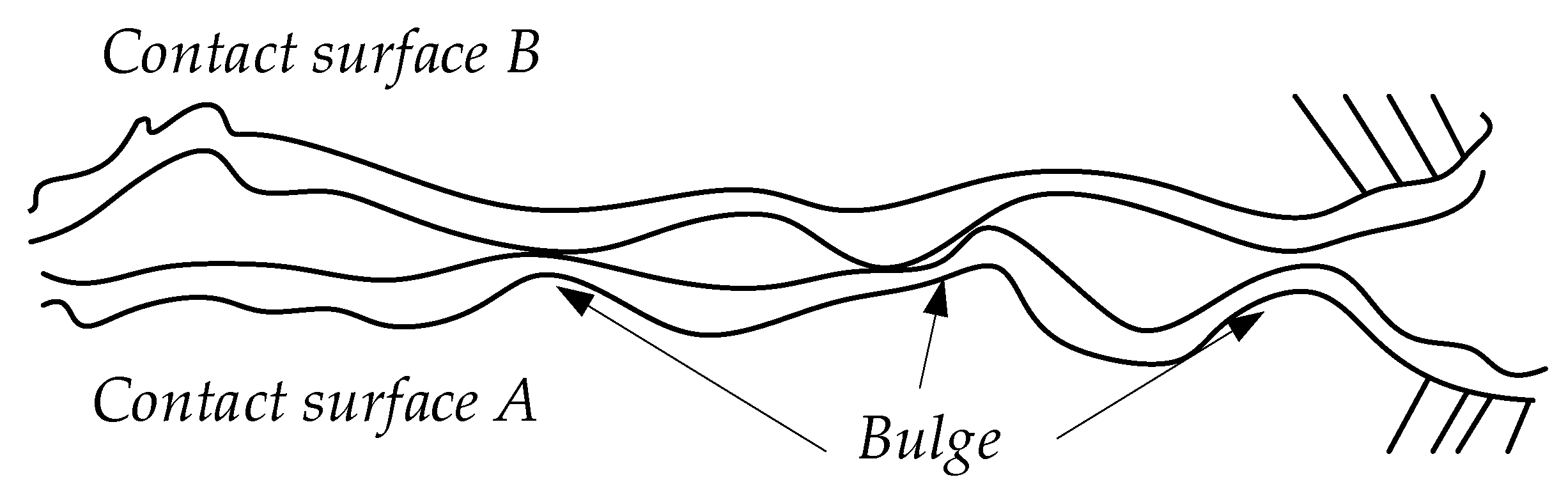
2.1. Causes of Friction

After a long period of research, it has been found that friction is a relatively complex phenomenon with many types and very different characteristics. When there is relative motion between the two contact surfaces, a friction force is generated between the contact surfaces, and the magnitude of the friction force is related to the characteristics of the contact surfaces. Because the contact surface of an object cannot be absolutely smooth, the friction characteristic is the contact of some tiny points protruding from the surface, which are called bulges [8], as shown in Figure 1.
In general, friction is a nonlinear time-varying physical quantity that is affected by many factors, and its characteristics can be divided into static and dynamic [9]. Coulomb friction, static friction, and the Stribeck effect are static characteristics, whereas dynamic characteristics include pre-slip displacement and friction hysteresis.

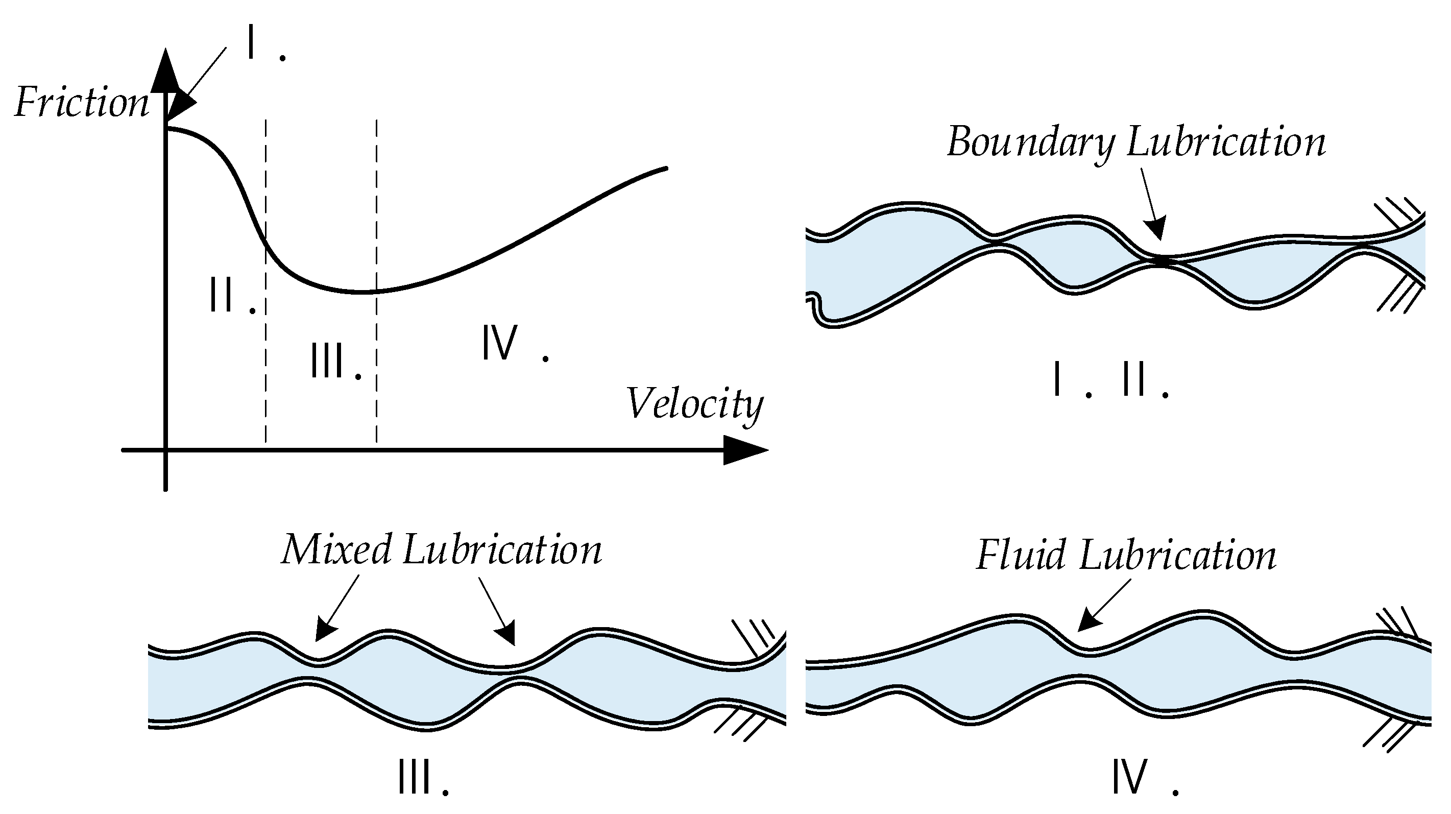
2.2. Static Characteristics of Friction

Stribeck [10,11] found that many frictions have static properties, as shown in Figure 2. By summarizing the observed friction phenomena, the friction characteristics were described as Stribeck curves. When the contact surface moves from rest to start, the friction as a function of velocity can be divided into four stages: static friction, boundary lubrication, partial fluid lubrication, and full fluid lubrication.
In the first stage, static friction is independent of velocity and can be identified as being generated by elastic deformation, which, from a control point of view, leads to increased static friction. At this time, the object is subjected to force but does not produce relative motion. Because the contact surface is deformed, the frictional force on the object at this time is equal to the external force, and the direction is the opposite. In the second stage, the relative speed of motion between the contacting surfaces is so low that a liquid film cannot be established between them, and the frictional force is caused by the shearing effect between the solids. Meanwhile, the frictional force significantly interferes with the motion response of the system, such as the low-speed crawling phenomenon. In the third stage, relative motion causes a liquid film to form between the contact surfaces. However, because of normal pressure, part of the lubricating liquid is squeezed out of the contact surfaces. Therefore, there are still some areas of solid contact, and the friction force decreases as the speed increases. In the fourth stage, the liquid film is fully formed and there are no longer areas of solid contact, therefore, the friction force decreases; however, with an increase in the relative motion speed, the effect of viscous friction becomes increasingly obvious, which becomes the main factor affecting the performance of the system.
Figure 2 shows the relationship between the friction force and the steady speed, which is a static characteristic of friction. Friction does not strictly follow this relationship when the speed and external force vary, but has other characteristics.

2.3. Dynamic Characteristics of Friction

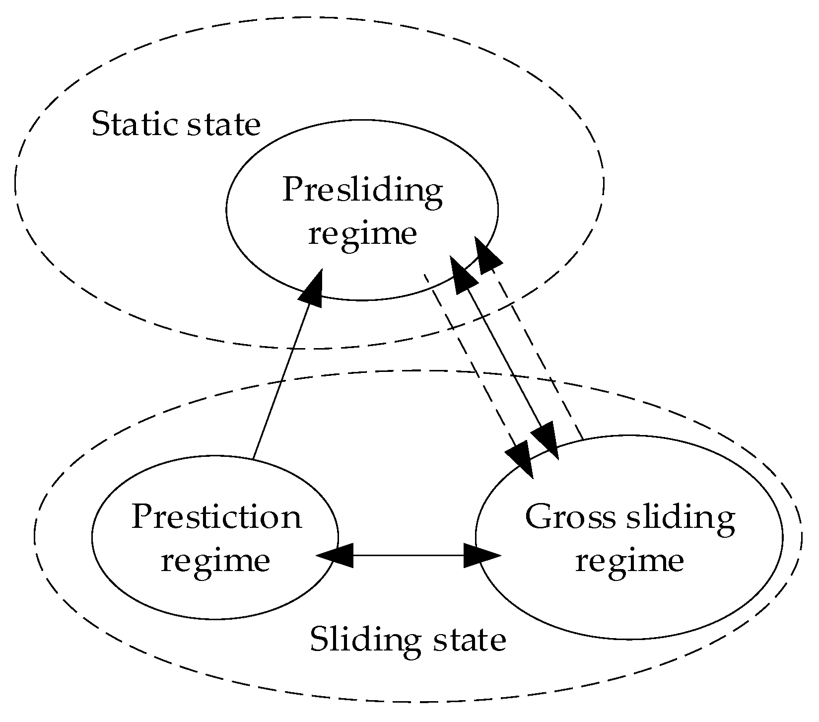
2.3.1. Pre-Sliding Displacement

This phenomenon was discovered by Dahl [12] and is shown in Figure 3a. When the object is in the static friction stage, although the object does not move, there is a small positional deviation owing to the deformation of the contact surface, which is called pre-displacement [13]. When the external force is removed, the object cannot completely return to its original position, and a certain residual displacement is retained.

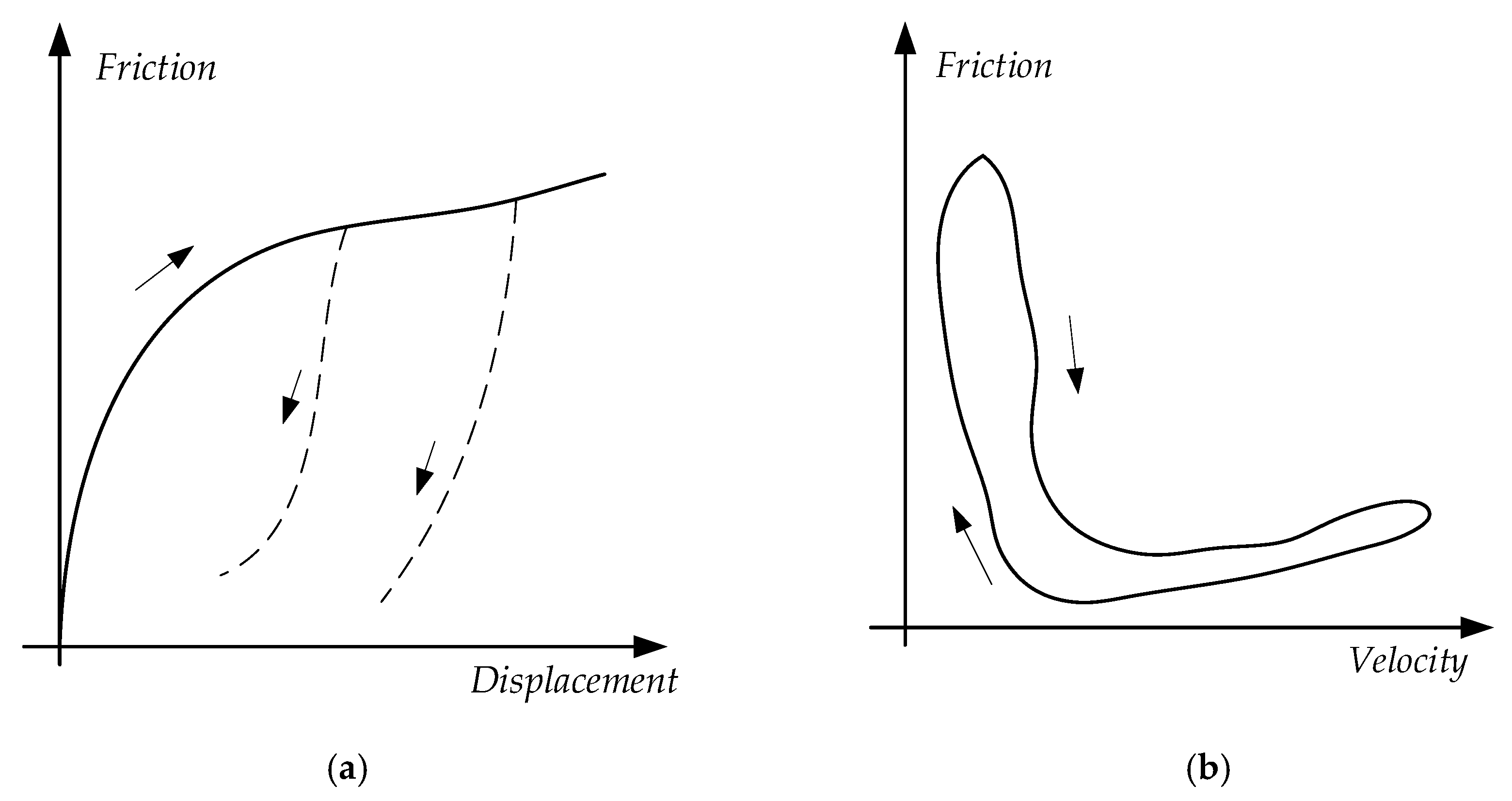
2.3.2. Friction Hysteresis

Frictional hysteresis [14,15,16] is also known as a frictional memory. As shown in Figure 3b, the friction force curves do not coincide when the speed gradually increases or decreases. The friction force during deceleration is lower than that during acceleration, forming a hysteresis loop, and the width of the hysteresis loop is proportional to the rate of speed change.

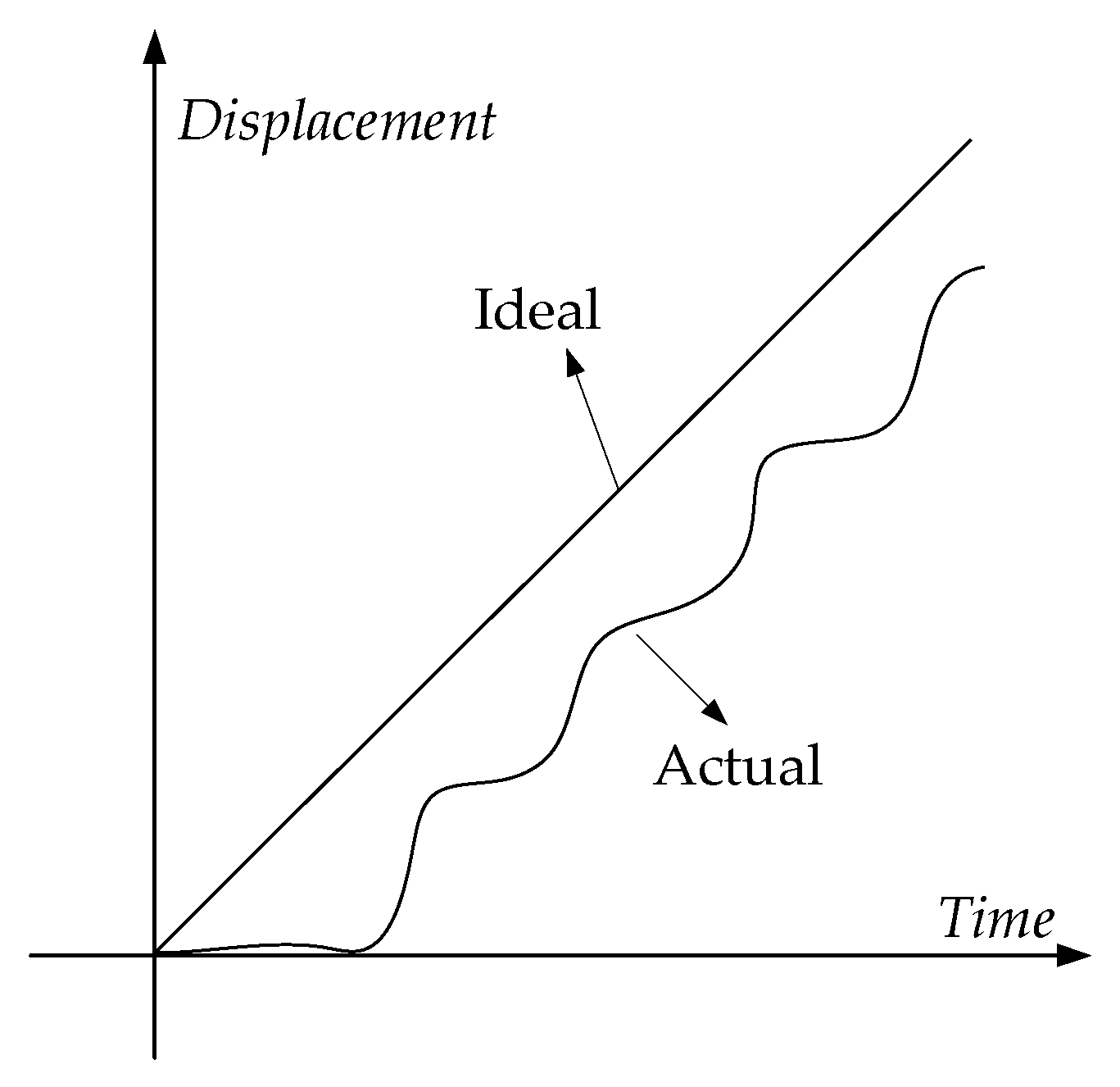
2.3.3. Crawling Phenomenon

As shown in Figure 4, crawling [17] indicates that when the operating speed of the system is lower than a certain critical value, its movement speed pulsates, which is also called low-speed jitter or low-speed instability. The essence of the crawling phenomenon is that when an object moves at a relatively low speed on a sliding surface, the phenomenon of alternating stopping and sliding under certain conditions is a type of discontinuous vibration. Typically, a slight degree of crawling is a vibration that is imperceptible to the eye, whereas a significant crawling is a large jump. The existence of frictional vibration destroys the uniformity of system motion, which not only produces impact, but also affects the accuracy of the control system.

2.3.4. Variable Static Friction

In the static friction range, the magnitude of the friction force is related to the growth rate of the external force, and the friction force decreases nonlinearly with increasing speed. Rabinowicz [18] determined the relationship between friction and displacement before the start of sliding, and found that the maximum friction force that was overcome by objects from relative static motion to relative motion was the maximum static friction force, as shown in Figure 5a. Johannes et al. [19] pointed out that the maximum static friction is not constant, but depends on the application rate of the external force, as shown in Figure 5b.
In addition, owing to the multi-valued, non-linear, negative slope, and other characteristics of the friction force, the servo system may produce unstable motion. The tracking accuracy of the speed signal and the position signal is affected, and even top distortion of the sinusoidal position signal and low-speed crawling occur. This affects the tracking performance of the servo systems. Therefore, it is necessary to study and control the friction characteristics of servo systems.

3. Friction Model and Its Identification Strategy

3.1. Friction Model

Scholars have conducted extensive research on friction models to accurately reflect the aforementioned friction characteristics. Currently, research on friction modeling has a history of hundreds of years, and dozens of friction models have been proposed. Depending on whether the friction phenomenon is described by differential equations, friction models can be roughly divided into two categories: static and dynamic [20].
Static models mainly include the Coulomb friction model [21], viscous friction and Coulomb friction model [22], static friction and Coulomb friction and viscous friction model [23], Stribeck model [24], and Karnopp model [25]. The static friction model uses a mathematical function whose independent variable is the relative velocity to represent the friction force, and has the advantages of a simple structure and easy parameter determination. To a certain extent, it can meet the requirements of control performance. However, it lacks the ability to explain the hysteresis effect and dynamic characteristics of friction. Dynamic models include the reset integral model [26], Bliman and Sorine model [27], Bristle model [28], LuGre model [29], Dahl model [30], Leuven friction model [31], Hsieh friction model [32] and Maxwell-slip friction model [33]. The dynamic friction model depicts friction as a function of the relative velocity and displacement. It can describe the static and dynamic characteristics of friction. Therefore, the dynamic model can more realistically describe the interface friction state.
Usually, only linear friction–viscous friction is considered in the model, whereas nonlinear friction is ignored. However, friction is an important aspect of many high-precision servo controls. It causes tracking errors, limits cycles, and crawl, and it affects system dynamics more than other nonlinear factors. To compensate for friction effects without high gains, a suitable friction model must be built to predict and compensate for friction. At the same time, better friction models are required for stability analysis, prediction of limit cycles, determination of control gains, and system simulation. Several friction models commonly used in the field of servo system control are briefly introduced in Table 1.

3.2. Friction Model Identification Algorithm

In general, the dynamic friction model has better continuous characteristics than the static friction model, and can better describe the nonlinear behavior of friction. However, the more comprehensive the description of the friction behavior, the more parameters and the more complex the structure. Consequently, several friction model parameter identification strategies have been developed. It is essentially a modeling method, and the main principle is to establish a system equivalent to an observation system based on input and output observations. In practical applications, a model is selected from a set of models. According to a certain standard, the model can describe the dynamic and static characteristics of the system observed in the test more accurately. By identifying the parameter data with small order of magnitude that are difficult to display in the model, the relevant data of the established friction model are corrected so that the simulation is closer to the real measurement result, and the operating index of the servo system can be detected more accurately. Currently, applied parameter identification methods are classified into classical and intelligent identification methods.
In general, the classical friction model parameter identification method has certain limitations. For example, the input signal must be high and the input signal must be changed over a large range such that the classical system identification method can effectively estimate the model parameters. In addition, classical identification methods are limited to linear links, whereas intelligent identification methods are used for nonlinear friction characteristics.

3.2.1. Classical Identification Methods

  • Least squares parameter estimation method.
Classical identification methods mainly use the Lyapunov function method, least squares method, and spectral analysis method to identify the friction parameters. The least squares parameter estimation method is simple in principle, small in calculation amount, fast in convergence speed, easy to implement, and widely used in friction model parameter identification. The least squares method, which was generalized by Dempster et al. [38] in 1977, is one of the most classical and basic parameter estimation methods. This includes batch processing least squares, recursive least squares, forgetting factor recursive least squares, and recursive augmented least squares.
Considering the problem of complex parameters of the friction model, in [39], a new refactored multiple innovation least squares (RMILS) method was constructed by introducing intermediate step size updates and decomposing innovation updates into sub-innovation updates. The inverse problem of the covariance matrix was solved and the recognition performance was improved. Lee et al. [40] proposed a fast parameter identification algorithm based on recursive least squares (RLS) for identifying the feed drive mass and sliding friction. Data processing was avoided, and a two-step identification technology was adopted to improve the identification accuracy and convergence rate. Liang and Zhou [41] used the separable least squares (SLS) method to perform nonlinear optimization in the servo drive mechanism, which significantly reduced the computational cost, did not require any inertial information, and avoided the noise introduced by the acceleration estimation. Simultaneously, these identification methods could be extended to other nonlinear mechanical systems to maintain their favorable characteristics.
2.
Parameter estimation method for experimental data.
The experimental data parameter estimation method is significantly different from the least squares parameter estimation method. The basic idea is to test the estimated values of the model parameters according to the specific experimental data until the experimental effect reaches the best state. In [42], a method based on the limit cycle characteristics of a mechanical system during vibration was proposed, and the oscillation amplitude was determined by adjusting the controller parameters to determine the static and Coulomb friction coefficients of the system. However, in real systems, friction is strongly nonlinear and varies with many factors such as posture, speed, and temperature. Therefore, all friction models deviate from the actual values, which reduces the recognition accuracy.
Wu et al. [43] proposed an identification method using substrate force sensors, which first identified the inertial parameters and then calculated the joint friction value by subtracting the inertial torque from the joint torque, which did not require a priori friction model. Yoo et al. [44] used a 90° phase relationship between acceleration and velocity in position control. The mechanical parameters were obtained from the integral value of the product of the torque, velocity, and position, and the moment of inertia and friction components were fully considered to effectively estimate the moment of inertia, viscous friction coefficient, and Coulomb friction in the offline state. Simulation and experimental results demonstrated that the proposed method was effective, accurate, simple to implement, and could easily be applied in industry.
The experimental data parameter estimation method has defects, such as a large amount of calculation and a complicated method, but the recognition accuracy is high, and it can fit the actual friction characteristics well.

3.2.2. Intelligent Identification Method

  • Neural network identification method.
The parameter identification method based on neural networks is more suitable for the establishment and control of complex models, and the nonlinear friction model can be identified by the method’s characteristics of infinite approximation of nonlinear mapping. The self-learning and self-adaptive abilities of neural networks are also very convenient for engineering applications. Lu et al. [45] combined direct backpropagation (BP) and neural dynamic programming (NDP) with particle swarm optimization (PSO), to construct a direct BP neural dynamic programming heuristic PSO (NDPSO). In NDPSO, the critic BP neural network was trained to balance the Bellman equation, whereas the action BP neural network was used to train the inertia weight, cognitive coefficient, and social coefficient of the PSO algorithm. The training goal was to make the critic BP neural network output close to the goal of final success. The experimental results clearly showed that NDPSO is effective in identifying static friction torque parameters in servo control systems and outperforms SPSO and GA.
As traditional static friction models cannot uniformly represent all friction situations, a backpropagation neural network (BPNN) was proposed to weaken the requirements of traditional static friction models. The relative velocities of the interacting surfaces and joint loads were typically considered as the inputs to the BPNN, and its output was the predicted static friction. Furthermore, to speed up convergence and improve the global generalization ability of the BPNN, a genetic algorithm (GA) was used to optimize the initial values of weights and thresholds. All training samples followed a reciprocating constant velocity experiment with friction under changes in joint speed and load. The experimental results showed that using the GA to optimize the initial values of the weights and thresholds was beneficial for improving the convergence rate and prediction accuracy of the network. Compared with the traditional static friction model, the BPNN model had higher prediction accuracy and excellent generalization ability [46].
Servo systems are also affected by other nonlinear factors in actual work. Liao et al. [47] constructed a nonlinear servo system with limits, dead zones, and correction coefficients caused by unknown factors. A neural network was used to identify the linear parameters, and the nonlinear parameters were determined based on the flow characteristic curve. Compared with the linear model without nonlinear factors, the fitting degree of the door opening was 98.445%, the power was 96.986%, and the output of the nonlinear model was in good agreement with the actual output. When the relative error of the stable result was 5% for valve opening and 1.58% for power, the error of the linear model was larger. The simulation results of the proposed method showed that the nonlinear factors of high-power units could not be ignored, and that the nonlinear model of the servo system was more accurate.
Neural networks can be effectively applied to the identification of nonlinear static or dynamic systems. There are two types of classical neural networks: multi-layer and recurrent. Multi-layer neural networks are mostly used in static nonlinear systems, whereas recurrent neural networks are used in dynamic nonlinear feedback systems. In more complex systems, both types of neural network are included. The advantage of the neural network identification method is that there is no need to establish a systematic identification format, and the learning algorithm determines the convergence speed of the identification. It can be applied to online identification to solve nonlinear problems of the system.
2.
Metaheuristics
To solve complex optimization problems that are difficult to solve using traditional optimization algorithms, researchers have proposed meta-heuristic algorithms inspired by biological and natural physical phenomena. A meta-heuristic algorithm is a type of stochastic optimization algorithm that simulates the behavior of social insects or animal swarms. Individuals in the algorithm can solve complex problems using simple behavior rules. Compared with the traditional optimization method, the swarm intelligence algorithm is independent of the initial value, gradient information, low function requirements, and good solution performance. Currently, the most common swarm intelligence algorithms include the ant colony algorithm (ACO) [48], artificial bee colony algorithm (ABC) [49], and glowworm swarm optimization (GSO) [50]. With the rise of meta-heuristic algorithms and the improvement in servo system control accuracy in recent years, many scholars have turned to meta-heuristic algorithms to identify friction model parameters.
Wang and Wang [51] proposed a novel identification method for the LuGre model, based on an evolutionary algorithm (EA) and statistical logic. The friction parameters were identified using a two-step method, the static parameters were identified using an isokinetic experiment, and the dynamic parameters were identified using the pre-slip process in the separation experiment. In addition, the asymmetry of the friction in the positive and negative rotation directions was considered. EA was used to enhance the optimal estimation of the friction parameters, which verified the effectiveness of the proposed identification method. As shown in Figure 6, in [52], a friction compensation control strategy based on the differential evolution algorithm was proposed and applied to the position control system of a pneumatic finger cylinder. However, this two-step method was not used for identification. Finally, the comparison results of this strategy with the traditional proportional derivative (PD) and friction compensation strategies showed that using the friction compensation strategy based on the differential evolution algorithm to optimize the local parameters could improve the position accuracy of the finger cylinder position control system.
As shown in Figure 7, Wong and Erkorkmaz [53] captured a series of motion data from a computer numerical control (CNC), and completed the rapid identification of a stability-constrained system based on a genetic algorithm. Compared with the Lagrangian multiplier solution, the GA was successfully used to predict the tracking and contour errors for different part-programs in a virtual process–planning environment. GA was recognized faster and improved by 2–3 orders of magnitude, making it more suitable for industrial use.
Chen et al. [54] proposed a parameter identification method based on the fireworks algorithm (FWA). According to the experimental data of the damper dynamic characteristics and the simulation data of the Bouc–Wen model, the FWA was used to identify the seven parameters of the Bouc–Wen model. Compared with the genetic algorithm (GA), differential evolution (DE) algorithm, and particle swarm optimization (PSO) algorithm, FWA had the advantages of fast convergence speed, short calculation time, and high stability in solving high-order parameter identification problems. Under the three types of harmonic excitations, the average calculation accuracies of the identified model reached 88.64%, 90.45%, and 81.28%, respectively, and the dynamic characteristic curve of the model was consistent with the experimental results.
As shown in Table 2, the standard meta-heuristic algorithm is increasingly being applied to friction parameter identification owing to its superior optimization performance. Inevitably, meta-heuristic algorithms have certain limitations such as slow convergence, easy precociousness, and falling into local optimal solutions. Many scholars have made in-depth improvements in this regard.
Yu et al. [55] constructed an improved Drosophila optimization algorithm (IFFOA) by adding an adaptive step-based transfer factor to a three-dimensional search space. The convergence rate of the algorithm was improved, local optima were avoided, and the algorithm was applied to the improved LuGre friction model parameter identification. Finally, experimental measurements of the device displacement, velocity, and shear force were used to validate the performance of the proposed model and the IFFOA. Shao et al. [56] combined chaos search and a Gaussian mutation operator into a traditional artificial fish swarm algorithm and proposed an improved artificial fish swarm algorithm (IAFSA) method. The effectiveness of the IAFSA was verified through steady-state response and dynamic friction experiments. A comparison of simulations performed at different frequencies and amplitudes showed that the proposed LuGre friction model with acceleration-dependent partial and nonlinear continuous switching functions could accurately simulate the dynamic friction characteristics of solenoid-valve actuator systems. The proposed modeling and parameter identification methods were applicable to many other high-speed mechanical systems with friction.
It can be seen from the above literature analysis that the improvement in the identification strategy is mainly reflected in the combined improvement of the friction model and meta-heuristic algorithm, which often has strong pertinence. With the surge in workload, some scholars have turned to purely algorithmic improvements to improve the universality of identification technology. Hung et al. [57] used constrained particle swarm optimization (CPSO) to estimate the parameters of a three-mass resonant servo control system based on the LuGre friction model to allow machines to operate simultaneously. Through parameter estimation and feedforward compensation of the model, the main effect of current variation in the mechanical system was successfully reflected. Gao et al. [58] improved the sparrow search algorithm using a multi-strategy method, optimized the local search ability of the algorithm, and applied it to the parameter identification of the friction model of the servo system. Chen et al. [59] analyzed the motion trajectory of the flower pollination algorithm for the first time, improved the equations of the algorithm exploration and utilization stages through the chaotic mapping method and optimal information-guided search, and proposed an enhanced global flower pollination algorithm (GFPA). The experimental results showed that GFPA had a better recognition effect.
The advantage of the intelligent identification method is that it does not depend on the characteristics of the model itself, the identification results can be obtained quickly, and good results can be achieved in the application. The classical identification strategy is simple in principle, convenient to implement, and fast in convergence. The characteristics of each identification strategy are presented in Table 3. In practical engineering, the identification strategy should be comprehensively selected in combination with the actual work requirements.
Table 2. Common meta-heuristics.
TitleAdvantageDisadvantageCommon Areas
Evolutionary Algorithms (EA) [46,51,52,53,60]Group and expandability.Programming is complex and its parameter dependence is high.Neural networks, data mining, parameter estimation, etc.
Particle Swarm Optimization (PSO) [45,57]Memory, fast search speed, few parameters, simple structure, etc.The optimization speed is slow, the convergence accuracy is not high, and the optimization results fluctuate significantly.Function optimization, neural network training, stochastic optimization problems, etc.
Artificial Fish Swarm Algorithm (AFSA) [56]The requirements for the properties of the objective function and parameter settings are low.The structure is complex, the optimization speed is slow, and the convergence accuracy is low.Job shop scheduling, function optimization.
Fireworks Algorithm (FWA) [54]The structure is simple, there are few parameters, and the robustness is strong.It is easy to mature prematurely, and the convergence precision is low.Topology optimization problems, reducer, spring problems, etc.
Fruit Fly Optimization Algorithm (FOA) [55]The process is simple, the control parameters are few, and it is easy to implement.The convergence speed is slow and highly dependent on the initial conditions, which are not conducive to high-dimensional processing.Structural engineering design optimization problems, wireless sensor network layouts, etc.
Flower Pollination Algorithm (FPA) [59]Few parameters, is easy to implement, and has strong global optimization ability.The optimization accuracy is low, the convergence speed is slow, and it easily falls into local minima.Function optimization, text clustering, etc.
Sparrow Search Algorithm (SSA) [58]The adjustment parameters are small, convergence accuracy is high, and robustness is good.Poor local search ability.Engineering optimization design problems, multi-classifier coefficient optimization, etc.

4. Friction Nonlinear Control Strategy

Research on friction identification strategy aims to accurately describe the friction characteristics of the servo system and establish a friction model that conforms to the servo system. Friction is treated as soon as it occurs to avoid its adverse effect on the servo system, thereby improving the control accuracy and fast response performance of the servo system. However, there are other nonlinearities in actual servo systems. When the output flow of the flow servo valve and the input signal cannot form a linear proportional relationship, that is, the common saturation and dead zone nonlinearity, it needs to be further studied using the control strategy and compensation method. Common basic compensation methods include model-based, model-free, and composite control strategies.

4.1. Control Strategy Based on Friction Model

The model-based friction compensation method is essentially feedforward compensation; however, it relies on the accuracy of the friction model and has uncertainties in the critical lubrication stage in the low-speed section; therefore, its application is limited. This method can be divided into two categories: fixed model and adaptive friction compensation.

4.1.1. Fixed Model Compensation

The fixed model compensation method can be described as follows: first, a friction compensation controller with fixed parameters is added to the standard control algorithm for fusion, and then the friction parameters are further obtained by offline identification. Cong et al. [60] designed an improved Stribeck friction model, based on actual experimental data, and identified its parameters using a genetic algorithm. As shown in Figure 8, based on the improved model, the inertial stabilization platform and feedforward control of the velocity stabilization loop in the closed-loop control system were designed to avoid chatter and limit cycle problems caused by changes in motion direction and excessive friction compensation. The experimental results showed that the vibration isolation performances of the tracking system and carrier turbulent vibration isolation system were better than those of the corresponding control system without the proposed nonlinear friction model compensation.
Aguilar-Avelar et al. [61] were the first to discuss modeling, identifying, and compensating for the effects of nonlinear friction on flywheel control. A new algorithm for stabilizing the pendulum in an upward unstable position and a feedback linearization-based controller with friction compensation were proposed. The experimental results showed that the proposed dynamic model of the asymmetric Coulomb friction component better characterized the real experimental platform of the system and yielded better stability and control performance with lower power consumption. Li et al. [62] proposed an improved Stribeck friction model (SFM) and an optimization algorithm that was consistent with the positioning platform. A compensator based on the friction model and disturbance observer (DOB) was simulated. The simulation results showed that the friction-model-based compensator (velocity recovery of 10.66%) showed better performance after adding perturbation compared with the DOB compensator (velocity recovery of 5.19%). In addition, a compensation comparison between Coulomb friction, traditional SFM, and modified SFM was performed. The experimental results showed that, compared with the Coulomb friction compensation, the following errors of the modified SFM compensation at 0.005 m/s and 0.05 m/s speed were increased by 67.67% and 51.63%, respectively.
The friction model-based control strategy includes a fixed-friction model compensation term. As the compensation term is a fixed friction model, it does not change during the entire control process. Therefore, the requirements for the accuracy of the friction model are extremely high; however, the actual system has time, temperature, and other factors that affect the friction, and the fixed friction compensation term inevitably has errors.
Therefore, the method of fixed friction compensation, on the one hand, needs to meet the high requirements of the accuracy of the model. However, it needs to be in an actual situation where the influence of the environment is extremely low, so that the fixed friction compensation can have a better effect.

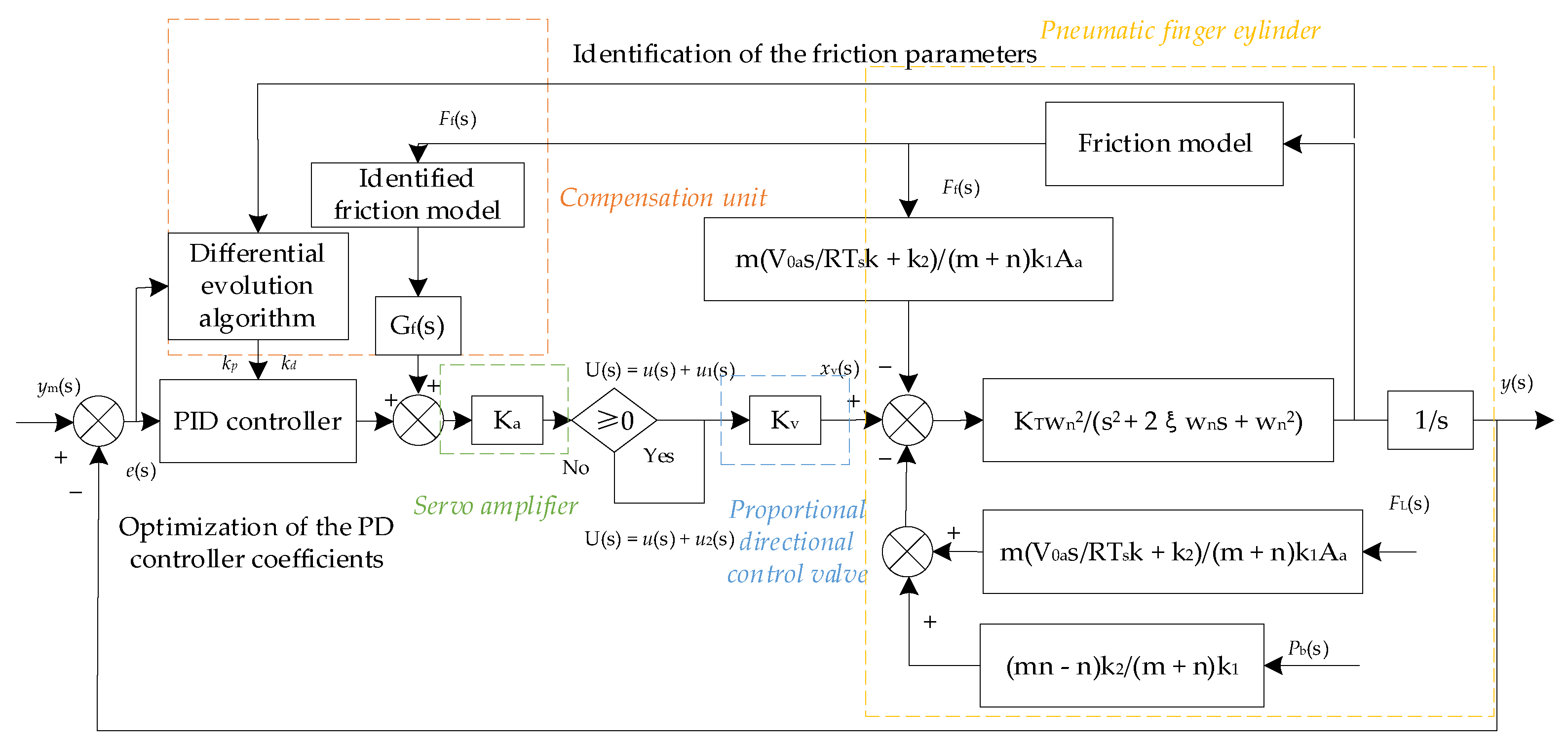
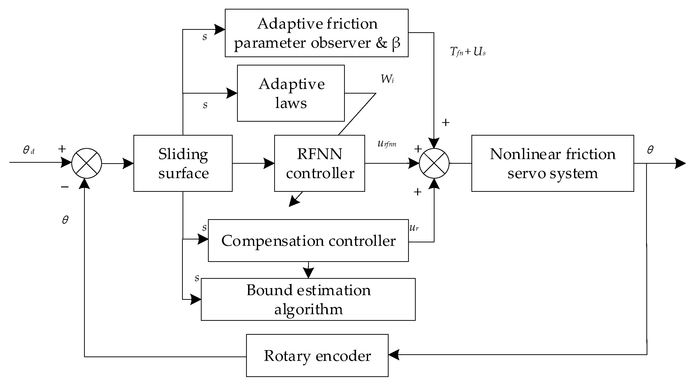
4.1.2. Adaptive Model Compensation

The adaptive model compensation method is described as follows. First, a specific static or dynamic friction model is selected. Then, the friction parameters are obtained through online estimation, and the system continuously adapts to the changes in the friction parameters to obtain the expected compensation effect. Li et al. [63] proposed an improved nonlinear friction compensation identification method with two degrees of freedom to guarantee accurate estimation of the frequency response of the underlying linear dynamics in practice. Then, an adaptive robust controller (ARC) with gain adjustment rules was synthesized to obtain guaranteed a robust performance in the presence of various uncertainties, improving the control performance achievable in practice.
Sancak and Bayraktaroglu [64] applied a Luenberger-like observer (LLO) and an extended state observer (ESO) to the experimental study of friction compensation in the high-precision tracking control of parallel manipulators. The performance of the proposed observer-based friction compensator was compared with that of a model-based compensator in terms of the computational torque control. The experimental results showed that the observer-based compensator significantly improved the tracking performance for high-speed motions. Among the surveyed observers, the ESO resulted in the smallest RMS error in position tracking. Improvements in position tracking upon velocity reversal of individual leg movements were also observed with observer-based compensation. The observer error dynamics were exponentially stable, and the convergence speed was arbitrarily increased by adjusting the observer gain.
The adaptive compensation scheme combines the determined controller with online model parameter estimation. The parameters of the friction model are obtained via online estimation. Online correction is performed according to the uncertainty of parameters under a specific model or the time-varying situation of parameters to solve the changes in friction parameters with time, temperature, and system operation. Good performance control of the electro–hydraulic servo system is obtained under the condition that the friction and object model parameters are constantly changing. Therefore, the adaptive model compensation is widely used in practical applications.

4.2. Friction Model-Free Control Strategy

From the perspective of system and control, there are many non-linear determinants of friction, and it is often difficult to establish a dynamic model that can reflect friction behavior. For example, in discontinuities near speed zero, flat tops, etc., these effects are difficult to predict and, therefore, difficult to counteract using traditional control laws. Furthermore, advanced control strategies are used to change the control parameters or structures, thereby improving the disturbance-suppression capability of the servo system. One part is the mechanical structure used to offset friction, and the other part is the model-free friction control strategy.

4.2.1. Mechanical Structure

The essence of the pulse control method is to compensate for a certain pulse signal in the input of the system so that the system can enter the dynamic friction state in advance and reduce the loss. In [65], the authors found that saturation occurred when the ratio of the two natural frequencies of a system with quadratic nonlinearity was approximately 2:1 and the system was excited at frequencies close to its higher natural frequency. The nonlinear factors can be suppressed by saturating the nonlinearity and paying special attention to the influence of dry friction on the stability boundary. The results showed that dry friction tends to shrink the stable region in some parts, but expanded other parts of the stable region. Friction, particularly its nonlinear component, could degrade the tracking performance of the robot. In the same year, Mei et al. [66] proposed a new nonlinear friction compensation method based on Kang’s method, which improved upon the traditional nonlinear friction compensation method. The enhanced tracking performance was verified under the SCARA robotics experimental platform using Windows NT and VenturCom real-time extension module (RTX) environment. Figure 9 shows a control block diagram of the nonlinear friction compensation method.
Torque feedback control involves installing a sensor of the measured motor output on the coupling shaft and forming a loop through feedback to achieve control. To overcome this problem, Carneiro and de Almeida [67] explored the use of a pneumatic actuation solution, that is, the pneumatic linear peristaltic actuator (PLPA). Experiments showed that, contrary to what happens with low-friction actuators, the use of integral action does not limit cycles. Furthermore, a zero steady-state control error was obtained in the closed-loop step response, suggesting that the proposed method may lead to a low-cost and simple motion control solution. In contrast to previous studies on this frictional active control mode, Benad et al. [68] devoted themselves to a theoretical analysis of sliding friction under the influence of in-plane oscillations perpendicular to the sliding direction. The effects of the frictional contact stiffness and displacement control system were considered in detail. The results showed that the contact stiffness plays a central role for small amplitudes, in which case the macroscopic friction coefficient was a function of two dimensionless parameters: the dimensionless sliding velocity and dimensionless oscillation amplitude.

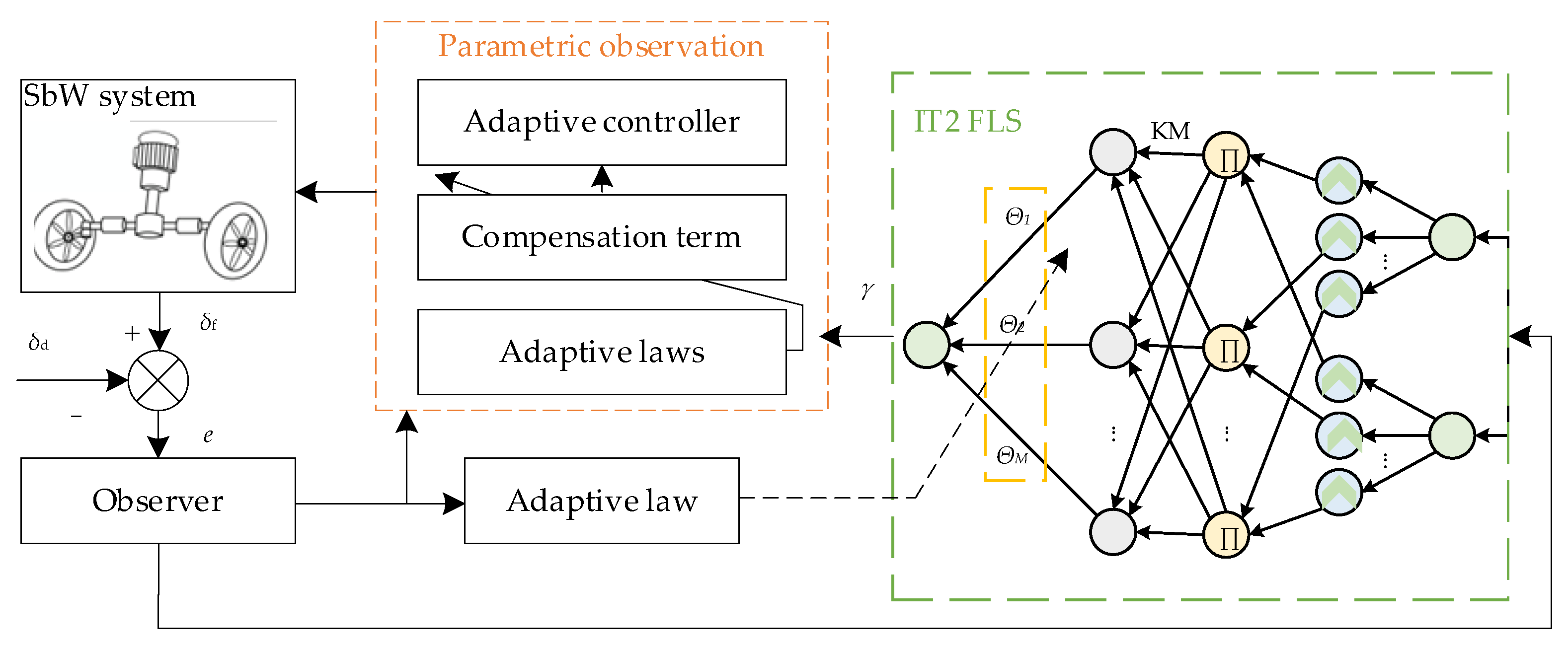
4.2.2. Model-Free Friction Compensation Methods

The principle of the model-free friction compensation method is that it regards friction as an external disturbance and improves the ability of the system to suppress disturbances and friction by changing the control structure or parameters. Compensation methods include the high-frequency vibration method, high-gain PD/PID control, variable structure control, disturbance observer design, impulse control, and robust control.
He et al. [69] proposed an adaptive robust dead-time compensation controller based on a backstepping method for an electro–hydraulic servo system (EHSS) with an unknown dead band and uncertain system parameters. Treating the variable load as the sum of the constant and variable parts, the constant part as one parameter of the system was estimated in real time, and the variable part, together with the friction as a disturbance. Therefore, robust terms in the controller can be used to reject them. Compared with the traditional dead-time compensation method, a dead-time compensator was added to the EHSS without constructing a dead-time inverse. Combined with the backstepping method, an adaptive robust controller (ARC) with dead-time compensation was developed. An easy-to-use ARC tuning method was proposed after further analysis of the ARC structure. The simulation results showed that the method had a good tracking performance, all uncertain parameters could be estimated, interference was suppressed, and dead zone terms were well estimated and compensated.
Yue and Li [70] designed an adaptive sliding mode control algorithm based on neural network friction compensation for optoelectronic tracking systems under friction and external disturbances. A neural network controller was used to identify nonlinear friction and integrate it into an adaptive sliding-mode control system under the Lyapunov framework. Experiments showed that the adaptive sliding mode controller with friction compensation could effectively reduce the influence of nonlinear friction and external disturbances of the optoelectronic tracking system using neural network approximation. Chuei and Cao [71] built an extreme learning machine-based hyper-twist repetitive control (ELMSTRC) based on an extreme learning machine hyper-twisting algorithm, repetitive control, and stable extreme learning machine-based hyper-twist control. Simulations and experiments showed that the nonlinear periodic perturbations, parameter uncertainty, nonlinear friction, and backlash were well controlled.
Wang et al. [72] introduced weighting factors to design model-based and model-free adaptive friction-compensation controllers. The role of friction in the control process was determined according to the weighting factor, and the damping characteristics of friction were fully utilized. On the one hand, it compensated for the friction that was detrimental to stability, and on the other hand, it utilized beneficial friction to improve the control performance. Numerical simulations demonstrated that the robust control problem of robotic manipulator systems with uncertain dynamics was well resolved. In the same year, Lee and Ryu [73] proposed a robust controller design for rotary motion control systems, which included a proportional–integral–derivative (PID) controller, disturbance observer, and friction compensator. A disturbance observer (DOB) based on simple and effective robust control theory enabled rotary motion control systems to be “robust” against inertia/load changes, external torque disturbances, and some frictional forces. The performance of the robust DOB-based motion control system was further enhanced by adding a friction compensator and was experimentally verified.
Xu et al. [74] proposed a backstep integral non-singular fast terminal sliding mode control method based on an extended state observer for trajectory tracking control of robotic manipulators with LuGre friction. An integral fast terminal sliding surface was introduced to improve the convergence speed and tracking accuracy. An appropriate saturation function was designed for the control input to avoid singularity, and the uncertainty and disturbance were estimated by the extended state observer and compensated by the control law to effectively eliminate jitter. The control input of the system was designed using the backstepping method to guarantee global asymptotic stability based on the Lyapunov criterion. Compared with other control methods, the simulation results demonstrated the effectiveness and superiority of this control scheme.
Model-free friction compensation treats friction effects as external disturbances and provides a new method to solve nonlinear friction problems in servo systems. The core control concept is to improve the ability of the system to suppress disturbances. The friction model was combined with other disturbances, and there was no exact friction model compensation. In the control term, the control structure and parameters were changed to ensure the accuracy of the system.

4.3. Composite Control Strategy

In [75], the authors classified the friction state into three states: the pre-slip state, total slip state, and predicted state. The relationships between these three states are shown in Figure 10. Comparative trajectory tracking experiments were conducted using an inertial-stabilized platform simulator for three control schemes: single proportional derivative (PD) control, PD based on LuGre model compensation, and PD with a compensator based on the proposed model. The experimental results showed that the control scheme based on this model had the best tracking performance, which reduced the peak-to-peak (PPV) of the tracking error to 0.2 m/rad, which was nearly 50% higher than the PD based on LuGre model compensation. Compared with the single PD control, the PPV error was reduced by 66.7%. It has been demonstrated that any control model has unique strengths and weaknesses. With advancements in science and technology, the requirements for precision are increasing, and a single control compensation method can no longer meet the needs of the researchers. Therefore, researchers have attempted to combine research models, give play to their advantages, remove the shortcomings of the models, take essence, and remove the dross, to form a composite control method.
A state observer [76] is to estimate the state signal of the system that cannot be directly measured according to the measurable output signal of the system. The observation of friction generally adopts this form. As shown in Figure 11, Han et al. [77] established a robust localization-control scheme using a friction parameter observer and a recurrent fuzzy neural network based on sliding mode control. The nonlinear dynamic friction was fully captured by the friction state observer, and an approximation method of the system uncertainty was developed using recursive fuzzy neural network technology to improve the positioning accuracy. Simulations and experiments were conducted to verify the performance of the proposed robust control scheme. Meng et al. [78] constructed an adaptive robust controller for dynamic friction compensation, based on the LuGre model. Online recursive least squares estimation (RLSE) was employed to reduce the degree of parameter uncertainty, and a sliding mode control method was employed to mitigate the effects of parameter estimation errors, unmodeled dynamics, and disturbances. An improved dual-observer structure was built to ensure the specified transient performance and final tracking accuracy of motion tracking. The recursive inference method was used to compensate for the uncertainty of the system model. To resolve the conflict between the sliding-mode control design and adaptive control design, projection mapping was used to adjust the RLSE algorithm to maintain parameter estimates within a known bounded convex set. The test results showed that the tracking performance of sinusoidal trajectories and smooth square trajectories under different loads and burst disturbances was very good, especially when tracking 0.5 Hz sinusoidal trajectories; the maximum tracking error was 0.96 mm, and the average tracking error was 0.45 mm.
Wu and Yue [79] synthesized a continuously differentiable nonlinear friction model of an electro–optic gyro-stabilized platform system by modifying the traditional piecewise continuous LuGre model and combining it with an adaptive robust controller to reduce the influence of measurement noise. Furthermore, the proposed controller theoretically guaranteed asymptotic output-tracking performance even in the presence of modeling uncertainty, thereby achieving the expected high control performance. Jiang et al. [80] considered the dynamic friction compensation problem of a networked Lagrangian system, designed a synchronous controller with better performance, and introduced the LuGre friction model to obtain an accurate description of friction. A tracking control algorithm for some uncertain parameters was provided, the control algorithm for some parameters had a lower computational complexity, and the control algorithm for uncertain parameters had the ability to adapt to changes by learning the tracking error. Both the control algorithms can achieve fast synchronization, and the simulation showed the effectiveness of the proposed tracking algorithm.
To eliminate the adverse effects of friction torque on the SbW system, Luo et al. [81] proposed an observer-based adaptive interval type two fuzzy logic system controller, as shown in Figure 12. First, the front wheel angular velocity was estimated by the observer, thereby reducing the sensitivity of the system to measurement noise, hardware cost, and structural complexity. The friction torque was then identified using an interval type two fuzzy logic system (IT2 FLS). Finally, an adaptive interval type two fuzzy logic system controller was proposed to achieve good tracking performance. The tracking error was guaranteed to asymptotically converge to zero using Lyapunov stability theory. Numerical simulations and hardware-in-the-loop (HIL) experiments verified the effectiveness and superiority of the proposed friction modeling method and control strategy.
When friction compensation is performed on an electro–hydraulic servo system, in general, to avoid unnecessary high gain, a single control compensation scheme should not be used [82,83]. Instead, various compensation methods should be integrated according to the specific conditions of the system to form a composite compensation control method, which is the development trend in friction and compensation research in electromechanical servo systems.

5. Discussion

5.1. Discussion of Friction Models

In comparison, the static friction model has a simple structure and easy parameter identification, but cannot describe the dynamic characteristics of friction; the dynamic friction model can describe the friction phenomenon comprehensively, but its structure is relatively complex and the parameter identification is difficult. Different mechanical systems require different degrees of difficulty for friction models, which are related to the essential characteristics of their respective problems. The accuracy of the friction model should be high when the sensitivity of the solution is significantly affected by the friction model. By contrast, a simple model was selected. At present, there are still some deficiencies in the research on friction modeling and the application of friction models, and further work should be carried out in the following aspects:
(1)
The establishment of the friction model should not simply describe the friction phenomenon but should be combined with the dynamic equation of the actual servo system, to comprehensively model it. A coupling relationship exists between the system and friction models. An unsuitable friction model may prevent the correct achievement of the expected behavior of the system dynamics model, and similarly, an unsuitable system dynamics model may limit the accuracy of the friction model;
(2)
When establishing a friction model, the software and hardware conditions for parameter identification should be considered, and the difficulty and practicability of friction parameter identification should be comprehensively considered. For a complex friction model, even if the friction phenomenon is described comprehensively, it is difficult to achieve parameter identification, which is undesirable, and a compromise solution should be chosen between practicability and complexity;
(3)
Most current verification methods for the accuracy of friction models are based on ideal conditions. However, the purpose of friction modeling is to apply the research results to practical mechanical systems to solve problems in their design, analysis, and control. Therefore, the applicability and feasibility of the friction model under the actual operating conditions must be verified.

5.2. Discussion on Friction Control Strategy

As friction compensation occupies a key position in the design of high-precision and high-performance servo systems, it has become a research hotspot for servo system control strategies. As shown in Table 4, the friction compensation for the servo system has different purposes, according to the different control requirements of the servo system.
Overall, regardless of the control strategy used, it is necessary to enable the servo system to achieve the corresponding performance index. Therefore, it is necessary to select the corresponding control strategy according to the performance index. If the performance index has high-accuracy requirements, sometimes a single control strategy cannot satisfy the requirements of the performance index. In particular, for a servo system with a relatively complex system, it is necessary to combine multiple control strategies to solve a situation in which a single control strategy does not satisfy the requirements. A summary of the friction-control strategy analysis is presented in Table 5.

6. Conclusions

Friction exists widely in electro–hydraulic servo systems and has a significant influence on the power mechanism of an electro–hydraulic servo system. To improve the accuracy of the power mechanism of the electro–hydraulic servo system, it is necessary to focus on the influence of friction on it. This study reviews the friction nonlinearity of servo systems, including the friction characteristics, friction model, friction model identification strategy, and friction nonlinear control strategy. The published friction model control strategies can be classified into three types: friction model-based, friction model-free, and composite controls. On this basis, the research direction of the friction model was proposed, and the advantages and limitations of the friction nonlinear control strategy were analyzed to provide ideas and solutions to the problem of poor performance of the servo system owing to nonlinear friction factors.

Author Contributions

Conceptualization, B.G., W.S., L.Z. and W.Z.; writing—original draft preparation, B.G., W.S. and H.Z.; writing—review and editing, B.G., W.S. and W.Z.; supervision, B.G. and L.Z.; project administration, B.G. All authors have read and agreed to the published version of the manuscript.

Funding

This research was funded by the Natural Science Foundation of Heilongjiang Province of China (grant no. LH2019E064), and the National Natural Science Foundation of China (grant no. 52075134).

Institutional Review Board Statement

Not applicable.

Informed Consent Statement

Not applicable.

Data Availability Statement

Not applicable.

Acknowledgments

The authors would like to thank the anonymous reviewers and academic editor for their valuable and constructive comments, which greatly improved the quality and integrity of this manuscript.

Conflicts of Interest

The authors declare no conflict of interest.

References

  1. Yao, J. Model-based nonlinear control of hydraulic servo systems: Challenges, developments and perspectives. Front. Mech. Eng. 2018, 13, 179–210. [Google Scholar] [CrossRef]
  2. Pennestrì, E.; Rossi, V.; Salvini, P.; Valentini, P.P. Review and comparison of dry friction force models. Nonlinear Dyn. 2016, 83, 1785–1801. [Google Scholar] [CrossRef]
  3. Gao, B.; Shen, W.; Guan, H.; Zhang, W.; Zheng, L. Review and Comparison of Clearance Control Strategies. Machines 2022, 10, 492. [Google Scholar] [CrossRef]
  4. Meng, Y.; Xu, J.; Jin, Z.; Prakash, B.; Hu, Y. A review of recent advances in tribology. Friction 2020, 8, 221–300. [Google Scholar] [CrossRef] [Green Version]
  5. Marques, F.; Flores, P.; Claro, J.C.; Lankarani, H.M. Modeling and analysis of friction including rolling effects in multibody dynamics: A review. Multibody Syst. Dyn. 2019, 45, 223–244. [Google Scholar] [CrossRef]
  6. Nguyen, K.T.; La, N.T.; Ho, K.T.; Ngo, Q.H.; Chu, N.H.; Nguyen, V.D. The effect of friction on the vibro-impact locomotion system: Modeling and dynamic response. Meccanica 2021, 56, 2121–2137. [Google Scholar] [CrossRef]
  7. Marques, F.; Woliński, Ł.; Wojtyra, M.; Flores, P.; Lankarani, H.M. An investigation of a novel LuGre-based friction force model. Mech. Mach. Theory 2021, 166, 104493. [Google Scholar] [CrossRef]
  8. Dai, W.; Yang, J.; Wiercigroch, M. Vibration energy flow transmission in systems with Coulomb friction. Int. J. Mech. Sci. 2022, 214, 106932. [Google Scholar] [CrossRef]
  9. Pan, Q.; Zeng, Y.; Li, Y.; Jiang, X.; Huang, M. Experimental investigation of friction behaviors for double-acting hydraulic actuators with different reciprocating seals. Tribol. Int. 2021, 153, 106506. [Google Scholar] [CrossRef]
  10. Márton, L.; Lantos, B. Identification and model-based compensation of striebeck friction. Acta Polytech. Hung. 2006, 3, 45–58. [Google Scholar]
  11. Hao, L.; Pagani, R.; Beschi, M.; Legnani, G. Dynamic and friction parameters of an industrial robot: Identification, comparison and repetitiveness analysis. Robotics 2021, 10, 49. [Google Scholar] [CrossRef]
  12. Dahl, P.R. Solid friction damping of mechanical vibrations. AIAA J. 1976, 14, 1675–1682. [Google Scholar] [CrossRef]
  13. Narayanaswami, V.; Tong, J.; Schifani, C.; Bloomfield, P.M.; Dahl, K.; Vasdev, N. Preclinical evaluation of TSPO and MAO-B PET radiotracers in an LPS model of neuroinflammation. PET Clin. 2021, 16, 233–247. [Google Scholar] [CrossRef] [PubMed]
  14. Hess, D.P.; Soom, A. Friction at a lubricated line contact operating at oscillating sliding velocities. ASME. J. Tribol. 1990, 112, 147–152. [Google Scholar] [CrossRef]
  15. Hu, J.; Song, H.; Sandfeld, S.; Liu, X.; Wei, Y. Multiscale study of the dynamic friction coefficient due to asperity plowing. Friction 2021, 9, 822–839. [Google Scholar] [CrossRef]
  16. Zhou, Z.; Zheng, X.; Wang, Q.; Chen, Z.; Sun, Y.; Liang, B. Modeling and simulation of point contact multibody system dynamics based on the 2D LuGre friction model. Mech. Mach. Theory 2021, 158, 104244. [Google Scholar] [CrossRef]
  17. Armstrong-Helouvry, B. Stick slip and control in low-speed motion. IEEE Trans. Autom. Control 1993, 38, 1483–1496. [Google Scholar] [CrossRef]
  18. Rabinowicz, E. The nature of the static and kinetic coefficients of friction. J. Appl. Phys. 1951, 22, 1373–1379. [Google Scholar] [CrossRef]
  19. Johannes, V.I.; Green, M.A.; Brockley, C.A. The role of the rate of application of the tangential force in determining the static friction coefficient. Wear 1973, 24, 381–385. [Google Scholar] [CrossRef]
  20. Kang, W.S.; Choi, C.K.; Yoo, H.H. Stochastic modeling of friction force and vibration analysis of a mechanical system using the model. J. Mech. Sci. Technol. 2015, 29, 3645–3652. [Google Scholar] [CrossRef]
  21. Armstrong-Hélouvry, B.; Dupont, P.; De Wit, C.C. A survey of models, analysis tools and compensation methods for the control of machines with friction. Automatica 1994, 30, 1083–1138. [Google Scholar] [CrossRef]
  22. Kelly, R.; Llamas, J.; Campa, R. A measurement procedure for viscous and coulomb friction. IEEE Trans. Instrum. Meas. 2000, 49, 857–861. [Google Scholar] [CrossRef]
  23. Virgala, I.; Frankovský, P.; Kenderová, M. Friction effect analysis of a DC motor. Am. J. Mech. Eng. 2013, 1, 1–5. [Google Scholar] [CrossRef] [Green Version]
  24. Xiang, W.; Yan, S.; Wu, J. Dynamic analysis of planar mechanical systems considering stick-slip and Stribeck effect in revolute clearance joints. Nonlinear Dyn. 2019, 95, 321–341. [Google Scholar] [CrossRef]
  25. Khan, Z.A.; Chacko, V.; Nazir, H. A review of friction models in interacting joints for durability design. Friction 2017, 5, 1–22. [Google Scholar] [CrossRef] [Green Version]
  26. Zhao, P.; Liu, J.; Li, Y.; Wu, C. A spring-damping contact force model considering normal friction for impact analysis. Nonlinear Dyn. 2021, 105, 1437–1457. [Google Scholar] [CrossRef]
  27. Jaiswal, S.; Sopanen, J.; Mikkola, A. Efficiency comparison of various friction models of a hydraulic cylinder in the framework of multibody system dynamics. Nonlinear Dyn. 2021, 104, 3497–3515. [Google Scholar] [CrossRef]
  28. Wei, Y.; Liu, S. Numerical analysis of the dynamic behavior of a rotor-bearing-brush seal system with bristle interference. J. Mech. Sci. Technol. 2019, 33, 3895–3903. [Google Scholar] [CrossRef]
  29. Lu, Y.; Zhang, J.; Yang, S.; Li, Z. Study on improvement of LuGre dynamical model and its application in vehicle handling dynamics. J. Mech. Sci. Technol. 2019, 33, 545–558. [Google Scholar] [CrossRef]
  30. Pennestri, E.; Valentini, P.P.; Vita, L. Multibody dynamics simulation of planar linkages with Dahl friction. Multibody Syst. Dyn. 2007, 17, 321–347. [Google Scholar] [CrossRef]
  31. Lampaert, V.; Swevers, J.; Al-Bender, F. Modification of the Leuven integrated friction model structure. IEEE Trans. Autom. Control 2002, 47, 683–687. [Google Scholar] [CrossRef] [Green Version]
  32. Lin, C.J.; Yau, H.T.; Tian, Y.C. Identification and compensation of nonlinear friction characteristics and precision control for a linear motor stage. IEEE/ASME Trans. Mechatron. 2012, 18, 1385–1396. [Google Scholar] [CrossRef]
  33. Ruderman, M. Presliding hysteresis damping of LuGre and Maxwell-slip friction models. Mechatronics 2015, 30, 225–230. [Google Scholar] [CrossRef]
  34. Wang, J.; Sui, Z.; Tian, Y.T.; Wang, X.; Fang, L. A speed optimization algorithm based on the contour error model of lag synchronization for CNC cam grinding. Int. J. Adv. Manuf. Technol. 2015, 80, 1421–1432. [Google Scholar] [CrossRef]
  35. Fu, G.; Zhou, L.; Lei, G.; Lu, C.; Deng, X.; Xie, L. A universal ensemble temperature-sensitive point combination model for spindle thermal error modeling. Int. J. Adv. Manuf. Technol. 2022, 119, 3377–3393. [Google Scholar] [CrossRef]
  36. Chen, X.; Jiang, S.; Wang, T. Dynamic modeling and analysis of multi-link mechanism considering lubrication clearance and flexible components. Nonlinear Dyn. 2022, 107, 3365–3383. [Google Scholar] [CrossRef]
  37. Das, J.; Mishra, S.K.; Saha, R.; Mookherjee, S.; Sanyal, D. Nonlinear modeling of an electrohydraulic actuation system via experiments and its characterization by means of neural network. J. Braz. Soc. Mech. Sci. Eng. 2018, 40, 58. [Google Scholar] [CrossRef]
  38. Dempster, A.P.; Schatzoff, M.; Wermuth, N. A simulation study of alternatives to ordinary least squares. J. Am. Stat. Assoc. 1977, 72, 77–91. [Google Scholar] [CrossRef]
  39. Li, L.; Zhang, H.; Ren, X. A modified multi-innovation algorithm to turntable servo system identification. Circuits Syst. Signal Process. 2020, 39, 4339–4353. [Google Scholar] [CrossRef]
  40. Lee, C.Y.; Hwang, S.H.; Nam, E.; Min, B.K. Identification of mass and sliding friction parameters of machine tool feed drive using recursive least squares method. Int. J. Adv. Manuf. Technol. 2020, 109, 2831–2844. [Google Scholar] [CrossRef]
  41. Liang, M.; Zhou, D. A Nonlinear Friction Identification Method Combining Separable Least Squares Approach and Kinematic Orthogonal Property. Int. J. Precis. Eng. Manuf. 2022, 23, 139–152. [Google Scholar] [CrossRef]
  42. Borsotto, B.; Godoy, E.; Beauvois, D.; Devaud, E. An identification method for static and coulomb friction coefficients. Int. J. Control Autom. Syst. 2009, 7, 305–310. [Google Scholar] [CrossRef]
  43. Wu, J.; Li, W.; Xiong, Z. Identification of robot dynamic model and joint frictions using a baseplate force sensor. Sci. China Technol. Sci. 2022, 65, 30–40. [Google Scholar] [CrossRef]
  44. Yoo, M.S.; Choi, S.C.; Park, S.W.; Yoon, Y.D. Identification of mechanical parameters for position-controlled servo systems using sinusoidal commands. J. Power Electron. 2020, 20, 1478–1487. [Google Scholar] [CrossRef]
  45. Lu, Y.; Yan, D.; Levy, D. Friction coefficient estimation in servo systems using neural dynamic programming inspired particle swarm search. Appl. Intell. 2015, 43, 1–14. [Google Scholar] [CrossRef]
  46. Tu, X.; Zhou, Y.; Zhao, P.; Cheng, X. Modeling the static friction in a robot joint by genetically optimized BP neural network. J. Intell. Robot. Syst. 2019, 94, 29–41. [Google Scholar] [CrossRef]
  47. Liao, J.L.; Yin, F.; Luo, Z.H.; Chen, B.; Sheng, D.R.; Yu, Z.T. The parameter identification method of steam turbine nonlinear servo system based on artificial neural network. J. Braz. Soc. Mech. Sci. Eng. 2018, 40, 165. [Google Scholar] [CrossRef]
  48. Liu, J.; Yang, J.; Liu, H.; Tian, X.; Gao, M. An improved ant colony algorithm for robot path planning. Soft Comput. 2017, 21, 5829–5839. [Google Scholar] [CrossRef]
  49. Zorarpacı, E.; Özel, S.A. Privacy preserving rule-based classifier using modified artificial bee colony algorithm. Expert Syst. Appl. 2021, 183, 115437. [Google Scholar] [CrossRef]
  50. Gao, B.; Shen, W.; Dai, Y.; Ye, Y.T. Parameter tuning of auto disturbance rejection controller based on improved glowworm swarm optimization algorithm. Assem. Autom. 2022. to be published. [Google Scholar] [CrossRef]
  51. Wang, X.; Wang, S. New approach of friction identification for electro-hydraulic servo system based on evolutionary algorithm and statistical logics with experiments. J. Mech. Sci. Technol. 2016, 30, 2311–2317. [Google Scholar] [CrossRef]
  52. Zhang, Y.; Li, K.; Xu, M.; Liu, J.; Yue, H. Medical Grabbing Servo System with Friction Compensation Based on the Differential Evolution Algorithm. Chin. J. Mech. Eng. 2021, 34, 107. [Google Scholar] [CrossRef]
  53. Wong, W.W.S.; Erkorkmaz, K. Constrained identification of virtual CNC drives using a genetic algorithm. Int. J. Adv. Manuf. Technol. 2010, 50, 275–288. [Google Scholar] [CrossRef]
  54. Chen, X.; Xu, L.; Zhang, S.; Zhao, S.; Liu, K. Parameter identification of the Bouc-Wen model for the magnetorheological damper using fireworks algorithm. J. Mech. Sci. Technol. 2022, 36, 2213–2224. [Google Scholar] [CrossRef]
  55. Yu, Y.; Li, Y.; Li, J. Parameter identification and sensitivity analysis of an improved LuGre friction model for magnetorheological elastomer base isolator. Meccanica 2015, 50, 2691–2707. [Google Scholar] [CrossRef]
  56. Shao, D.; Xu, S.C.; Du, A.M. Dynamic friction modeling and parameter identification for electromagnetic valve actuator. J. Cent. South Univ. 2018, 25, 3004–3020. [Google Scholar] [CrossRef]
  57. Hung, Y.H.; Lee, C.Y.; Tsai, C.H.; Lu, Y.M. Constrained particle swarm optimization for health maintenance in three-mass resonant servo control system with LuGre friction model. Ann. Oper. Res. 2022, 311, 131–150. [Google Scholar] [CrossRef]
  58. Gao, B.; Shen, W.; Guan, H.; Zheng, L.; Zhang, W. Research on Multi-Strategy Improved Evolutionary Sparrow Search Algorithm and its Application. IEEE Access 2022, 10, 62520–62534. [Google Scholar] [CrossRef]
  59. Chen, Y.; Pi, D.; Wang, B. Enhanced global flower pollination algorithm for parameter identification of chaotic and hyper-chaotic system. Nonlinear Dyn. 2019, 97, 1343–1358. [Google Scholar] [CrossRef]
  60. Cong, S.; Deng, K.; Shang, W.; Kong, D.; Shen, H. Isolation control for inertially stabilized platform based on nonlinear friction compensation. Nonlinear Dyn. 2016, 84, 1123–1133. [Google Scholar] [CrossRef]
  61. Aguilar-Avelar, C.; Rodríguez-Calderón, R.; Puga-Guzmán, S.; Moreno-Valenzuela, J. Effects of nonlinear friction compensation in the inertia wheel pendulum. J. Mech. Sci. Technol. 2017, 31, 4425–4433. [Google Scholar] [CrossRef]
  62. Li, F.T.; Ma, L.; Mi, L.T.; Zeng, Y.X.; Jin, N.B.; Gao, Y.L. Friction identification and compensation design for precision positioning. Adv. Manuf. 2017, 5, 120–129. [Google Scholar] [CrossRef]
  63. Li, C.; Chen, Z.; Yao, B. Identification and adaptive robust precision motion control of systems with nonlinear friction. Nonlinear Dyn. 2019, 95, 995–1007. [Google Scholar] [CrossRef]
  64. Sancak, K.V.; Bayraktaroglu, Z.Y. Observer-based friction compensation in heavy-duty parallel robot control. J. Mech. Sci. Technol. 2021, 35, 3693–3704. [Google Scholar] [CrossRef]
  65. Shoeybi, M.; Ghorashi, M. Nonlinear vibration control of a system with dry friction and viscous damping using the saturation phenomenon. Nonlinear Dyn. 2006, 45, 249–272. [Google Scholar] [CrossRef]
  66. Mei, Z.Q.; Xue, Y.C.; Yang, R.Q. Nonlinear friction compensation in mechatronic servo systems. Int. J. Adv. Manuf. Technol. 2006, 30, 693–699. [Google Scholar] [CrossRef]
  67. Carneiro, J.F.; de Almeida, F.G. Friction characteristics and servo control of a linear peristaltic actuator. Int. J. Adv. Manuf. Technol. 2018, 96, 2117–2126. [Google Scholar] [CrossRef]
  68. Benad, J.; Nakano, K.; Popov, V.L.; Popov, M. Active control of friction by transverse oscillations. Friction 2019, 7, 74–85. [Google Scholar] [CrossRef] [Green Version]
  69. He, Y.; Wang, J.; Hao, R. Adaptive robust dead-zone compensation control of electro-hydraulic servo systems with load disturbance rejection. J. Syst. Sci. Complex. 2015, 28, 341–359. [Google Scholar] [CrossRef]
  70. Yue, F.; Li, X. Adaptive sliding mode control based on friction compensation for opto-electronic tracking system using neural network approximations. Nonlinear Dyn. 2019, 96, 2601–2612. [Google Scholar] [CrossRef]
  71. Chuei, R.; Cao, Z. Extreme learning machine-based super-twisting repetitive control for aperiodic disturbance, parameter uncertainty, friction, and backlash compensations of a brushless DC servo motor. Neural Comput. Appl. 2020, 32, 14483–14495. [Google Scholar] [CrossRef]
  72. Wang, Q.; Zhuang, H.; Duan, Z.; Wang, Q. Robust control of uncertain robotic systems: An adaptive friction compensation approach. Sci. China Technol. Sci. 2021, 64, 1228–1237. [Google Scholar] [CrossRef]
  73. Lee, H.S.; Ryu, S. Design of a robust controller for a rotary motion control system: Disturbance compensation approach. Microsyst. Technol. 2021, 27, 2293–2302. [Google Scholar] [CrossRef]
  74. Xu, Z.; Yang, X.; Zhang, W.; Zhang, W.; Zhang, L.; Liu, P.X. Backstepping Sliding Mode Control Based on Extended State Observer for Robotic Manipulators with LuGre Friction. Int. J. Control Autom. Syst. 2022, 20, 2054–2066. [Google Scholar] [CrossRef]
  75. Li, Z.Q.; Zhou, Q.K.; Zhang, Z.Y.; Zhang, L.C.; Fan, D.P. Prestiction friction compensation in direct-drive mechatronics systems. J. Cent. South Univ. 2013, 20, 3031–3041. [Google Scholar] [CrossRef]
  76. Chan, J.C.L.; Lee, T.H. Sliding mode observer-based fault-tolerant secondary control of microgrids. Electronics 2020, 9, 1417. [Google Scholar] [CrossRef]
  77. Han, S.I.; Jeong, C.S.; Yang, S.Y. Robust sliding mode control for uncertain servo system using friction observer and recurrent fuzzy neural networks? J. Mech. Sci. Technol. 2012, 26, 1149–1159. [Google Scholar] [CrossRef]
  78. Meng, D.; Tao, G.; Liu, H.; Zhu, X. Adaptive robust motion trajectory tracking control of pneumatic cylinders with LuGre model-based friction compensation. Chin. J. Mech. Eng. 2014, 27, 802–815. [Google Scholar] [CrossRef]
  79. Wu, Y.; Yue, D. Desired compensation adaptive robust control of electrical-optical gyro-stabilized platform with continuous friction compensation using modified LuGre model. Int. J. Control Autom. Syst. 2018, 16, 2264–2272. [Google Scholar] [CrossRef]
  80. Jiang, N.; Xu, J.; Zhang, S. Distributed adaptive synchronization control with friction compensation of networked lagrange systems. Int. J. Control Autom. Syst. 2018, 16, 1038–1048. [Google Scholar] [CrossRef]
  81. Luo, G.; Wang, Z.; Ma, B.; Wang, Y.; Xu, J. Observer-based interval type-2 fuzzy friction modeling and compensation control for steer-by-wire system. Neural Comput. Appl. 2021, 33, 10429–10448. [Google Scholar] [CrossRef]
  82. Gao, B.; Shen, W.; Dai, Y.; Wang, W. A Kind of Electro-hydraulic Servo System Cooperative Control Simulation: An Experimental Research. Recent Adv. Electr. Electron. Eng. 2022. to be published. [Google Scholar] [CrossRef]
  83. Gao, B.; Shen, W.; Zhao, H.; Zhang, W.; Zheng, L. Reverse Nonlinear Sparrow Search Algorithm Based on the Penalty Mechanism for Multi-Parameter Identification Model Method of an Electro-Hydraulic Servo System. Machines 2022, 10, 561. [Google Scholar] [CrossRef]
  84. Dólleman, P.; Carneiro, J.F.; Gomes de Almeida, F. Exploring the use of two servo-valves for servo-pneumatic control. Int. J. Adv. Manuf. Technol. 2018, 97, 3963–3980. [Google Scholar] [CrossRef]
  85. Kim, H.M.; Han, S.I.; Kim, J.S. Precision position control of servo systems using adaptive back-stepping and recurrent fuzzy neural networks. J. Mech. Sci. Technol. 2009, 23, 3059–3070. [Google Scholar] [CrossRef] [Green Version]
  86. Hu, H.; Wang, Y.; Sun, G. Hybrid adaptive compensation control scheme for high-precision servo system. Trans. Tianjin Univ. 2013, 19, 217–224. [Google Scholar] [CrossRef]
Figure 1. Microgram of contact surface sketch.
Machines 10 00568 g001
Figure 2. Stribeck curve diagram: (Ⅰ) Static friction; (Ⅱ) Boundary lubrication; (Ⅲ) Partial fluid lubrication; (Ⅳ) Full fluid lubrication.
Machines 10 00568 g002
Figure 3. Friction properties: (a) Pre-sliding placement; (b) Friction hysteresis.
Machines 10 00568 g003
Figure 4. Crawling phenomenon.
Machines 10 00568 g004
Figure 5. Friction properties: (a) Maximum static friction force; (b) Variable static friction.
Machines 10 00568 g005
Figure 6. Control structure chart of friction identification compensation [52].
Machines 10 00568 g006
Figure 7. Overview of rapid identification scheme [53].
Machines 10 00568 g007
Figure 8. Open-loop nonlinear system model of velocity [60].
Machines 10 00568 g008
Figure 9. Block diagram of an implementation of a controller [66].
Machines 10 00568 g009
Figure 10. Transition diagram of friction regime [75].
Machines 10 00568 g010
Figure 11. Block diagram of the proposed control system [77].
Machines 10 00568 g011
Figure 12. Observer-based adaptive interval type two fuzzy logic system controller [81].
Machines 10 00568 g012
Table 1. Friction model and its description characteristics.
Friction ModelAdvantagesDisadvantageDescriptive Features
Classical model [21,22,23]It is simple and parameter identification is easy.Discontinuous, the friction characteristics are not accurately described.Based on the Coulomb friction model, it notes that there is static friction and that friction is related to speed.
Stribeck model [24]Obtains a smooth transition between static friction and viscous friction.Inability to describe friction dynamics.A relatively complete description of the static characteristics of friction.
Karnopp model [25]Embodies viscous damping, Coulomb friction, and static friction to avoid switching between viscous and sliding friction equations of state.It is difficult to determine the concept of a zero-speed interval, and it cannot reflect the dynamic characteristics.A small viscosity interval is constructed to reduce the low-speed detection requirements.
Dahl model [30]The pre-slip displacement and friction hysteresis are described more accurately.The Stribeck effect is not described.Partial differential equations are used to describe the dynamic friction process.
Bristle model [28]Microscopic description of bump characteristics.The number of calculations is large.An integral algorithm is used.
Bliman–Sorine model [27]It can describe the Stribeck effect when the motion is commutated.The Stribeck effect, friction memory, and variable static friction are not described.The two Dahl models with different orders work together.
Time lag model [34]Demonstrates frictional memory behavior.Descriptions of other friction phenomena are missing.Fitting of the relative sliding velocities.
Reset integral model [26]The stress of the joint is reflected, and the simulation is effective.Discontinuous.Additional state variable z.
LuGre model [29]More complete description of dynamic and static characteristics.Difficult to identify.An amount of bristle deformation z is introduced to synthesize the Stribeck effect.
Ensemble model [35]The dynamic and static characteristics are described qualitatively.This involves two state-interval switching problems, and the structure is complex.Friction-state model switching description.
Dynamic correction model [36]Modifies the above model.Its applicability is poor, and the scope of application is limited.The parameters change dynamically.
Neural network model [37]Friction model structure and parameter identification should be avoided.The training is difficult, time-consuming, and computationally intensive.Neural networks.
Table 3. Performance comparison of each identification method.
Identification MethodAccuracyComplexityLinearNonlinearApplicable ScopeAdvantagesDisadvantages
Classical methodLowHighHighLowHighThe principle is concise, the number of calculations is small, the convergence speed is fast, and it is easy to implement.The requirements for the input signal are relatively high, and the nonlinear system identification ability is poor.
Neural networksHighMediumHighHighMediumSelf-learning and self-adaptive abilities.There are many sample requirements, and the training time is long.
MetaheuristicsHighLowHighHighHighIt is widely used and does not depend on the characteristics of the model.The algorithm is not perfect, and there are problems, such as premature convergence to the local optimal solution.
Table 4. Purpose of friction compensation.
System CharacteristicsFriction EffectCompensation Purpose
Bidirectional operation [84]Discontinuity of speed zeroEliminate movement discontinuities
One-way, low-speed operation [85]Crawling phenomenonEliminate crawling
One-way, high-speed operation [86]Large following errorReduce/eliminate following error
Table 5. Comprehensive analysis of friction control strategies.
Control StrategyAccuracyComplexityApplicabilityAdvantagesDisadvantages
Control based on friction modelFixed model compensationLowHighHighSimple structure and convenient design.Over-reliance on the accuracy of the friction model.
Adaptive model compensationMediumHighHighAchieve online parameter correction, etc.
Friction model-free controlMechanical structureHighLowLowHigh control accuracy.The implementation cost is high, and the structure is complex.
Model-free friction compensationMediumMediumHighThe servo system has strong anti-interference ability.It is necessary to consider nonlinear factors comprehensively.
Composite controlHighMediumMediumSuperior control performance, good stability.It is necessary to coordinate the coupling relationship between controllers.
Publisher’s Note: MDPI stays neutral with regard to jurisdictional claims in published maps and institutional affiliations.

