Article

Study on Mechanism of Roundness Improvement by the Internal Magnetic Abrasive Finishing Process Using Magnetic Machining Tool

1
Graduate School of Engineering, Utsunomiya University, 7-1-2 Yoto, Utsunomiya 321-8585, Tochigi, Japan
2
School of Engineering, Course of Mechanical Engineering Systems, Utsunomiya University, 7-1-2 Yoto, Utsunomiya 321-8585, Tochigi, Japan
*
Author to whom correspondence should be addressed.
Machines 2022, 10(2), 112; https://doi.org/10.3390/machines10020112
Submission received: 31 December 2021 / Revised: 26 January 2022 / Accepted: 29 January 2022 / Published: 2 February 2022
(This article belongs to the Special Issue High Precision Abrasive Machining: Machines, Processes and Systems)

Abstract

:
An internal magnetic abrasive finishing process using a magnetic machining tool was proposed for finishing the internal surface of the thick tubes. It has been proved that this process is effective for finishing thick tubes, and it can improve the roundness while improving the roughness. However, the mechanism of improving the roundness is not clear, so it is necessary to study it theoretically. In this research, firstly, the roundness curve expression was derived using the principle of roundness measurement by the assumed center method, and the expression of roundness curve expanded by Fourier series was obtained. The influencing factors of roundness improvement were then analyzed. Secondly, the experiments were carried out on SUS304 stainless steel tubes. By confirming the mechanism analysis results and the experimental results, it was concluded that the internal magnetic abrasive finishing process using the magnetic machining tool was effective for improving the roundness of the thick tubes whose thickness is from 10 mm to 30 mm. As the thickness of the tube increased, the improvement in roundness decreased.

1. Introduction

A high-precision internal surface of clean gas cylinders and gas piping systems used in the semiconductor manufacturing industry is required to prevent the adhesion of contaminants. The magnetic field-assisted finishing process has been proposed for machining highly finished internal surfaces that are difficult to process with ordinary tools and labor [1,2,3,4]. Utilizing the penetrability of magnetic field lines, the application of magnetic force has great advantages for the precision machining of internal surfaces. Therefore, there have been many studies on the internal surface finishing process using the finishing force generated by magnetic field. Shinmura et al. developed an internal finishing process based on the application of magnetic abrasive machining, and it was confirmed that this process is applicable to the internal finishing of the bottom of a clean gas bomb with a narrow opening which is hard to finish by the conventional finishing process [5]. In addition, Shinmura et al. developed an internal magnetic abrasive finishing process for nonferromagnetic complex-shaped tubes consisting of bent and straight sections and achieved the nearly uniform internal finishing of bent tubes by a single processing iteration [6]. Yamaguchi et al. proposed the magnetic abrasive finishing process using multiple pole-tip systems to finish the entire internal surface of capillary tubes and a method to define a pole-tip feed length that can achieve a uniform surface roughness on the entire target surface by calculating the pole-tip coverage time over the target surface. Moreover, they clarified the finishing characteristic and mechanism and showed the effects of the tool’s magnetic properties on the tool and abrasive motion and the interior finishing characteristic of capillary tubes [7,8]. Jain et al. developed a precision finishing process for complex internal geometries using a smart magnetorheological polishing fluid and discussed the process performance in terms of surface roughness reduction, concluding that the reduction in surface roughness value increases with an increase in the current (A) and the number of finishing cycles [9,10,11]. Kim et al. developed an internal polishing system using magnetic force for the production of ultra-clean tubes with average surface roughness ranging from 0.02 μm to 0.05 μm or less and the application of magnetic abrasives composed of WC/Co powder. They concluded that for highly efficient machining, large-size particles #90 are appropriate because the magnetic abrasives must be attracted sufficiently by the magnetic force. Furthermore, the supplied amount of magnetic abrasives was a very important variable for the improvement of surface roughness [12]. In addition, the stochastic approach to experimental analysis of the cylindrical lapping process was studied and it was concluded that lapping pressure has a significant effect on the efficiency of cylindrical lapping [13]. Wang et al. studied a high-precision polishing method for magnetic gel abrasive finishing and developed a rotating cylinder-based magnetic finishing setup to allow the gel abrasive and workpieces to tumble and rotate together during the polishing process to finish the internal surface of the stainless tubes [14,15]. Zou et al. developed an internal magnetic abrasive finishing process using a magnetic machining tool to improve the roughness and the roundness of the internal surface of a thick tube [16]. They also developed a new internal finishing process for tubes which is the magnetic abrasive finishing process combined with electrochemical machining [17]. In other respects, regarding the abrasive machining, Pereira et al. studied the super abrasive machining of integral rotary components using grinding flank tools and concluded that super abrasive machining implies a suitable, controllable, and predictable process for improving the manufacture of aeronautical critical components, such as Integrally Bladed Rotors [18]. The authors studied the isotropic finishing of austempered iron casting cylindrical parts by roller burnishing and concluded that the technique greatly improves surface roughness and eliminates the kinematic-driven roughness pattern of turning, leading to a more isotropic finishing [19].
Initially, the precision machining of an internal surface occurs by magnetic abrasive finishing, which relies on the magnetic force generated by magnetic particles put inside the tube and magnetic poles outside. It has been proven that this process is effective for finishing the thin tubes (with a thickness less than 5 mm) [20]. However, when the thickness of the tube increases, the magnetic force (finishing force) is also weakened, which makes it impossible to process. In order to solve this problem, the process of magnetic abrasive finishing using a magnetic machining tool was proposed [21]. In this process, the magnetic force (finishing force) can be enhanced by placing a magnetic machining tool inside the tube, which consists of permanent magnets and a yoke, and it is dozens of times higher than the process using magnetic particles. It has been proved that this process is effective for finishing the internal surface of the thick tubes.
In previous research, it has been concluded that this process can improve roundness while improving roughness [22]. However, the mechanism of improving the roundness is not clear, so it is necessary to study it theoretically. Therefore, this research mainly studies the mechanism of roundness improvement and clarifies the factors influencing the roundness improvement of internal surfaces.
In this research, firstly, the roundness curve expression was derived using the principle of roundness measurement by the assumed center method, and the expression of roundness curve expanded by the Fourier series was obtained. Secondly, the process of roundness change was analyzed, and then the factors influencing the roundness improvement were discussed. Finally, the thickness of the tube was adjusted to 10 mm, 20 mm, and 30 mm, respectively, and then experiments on a SUS304 stainless steel tube were carried out.

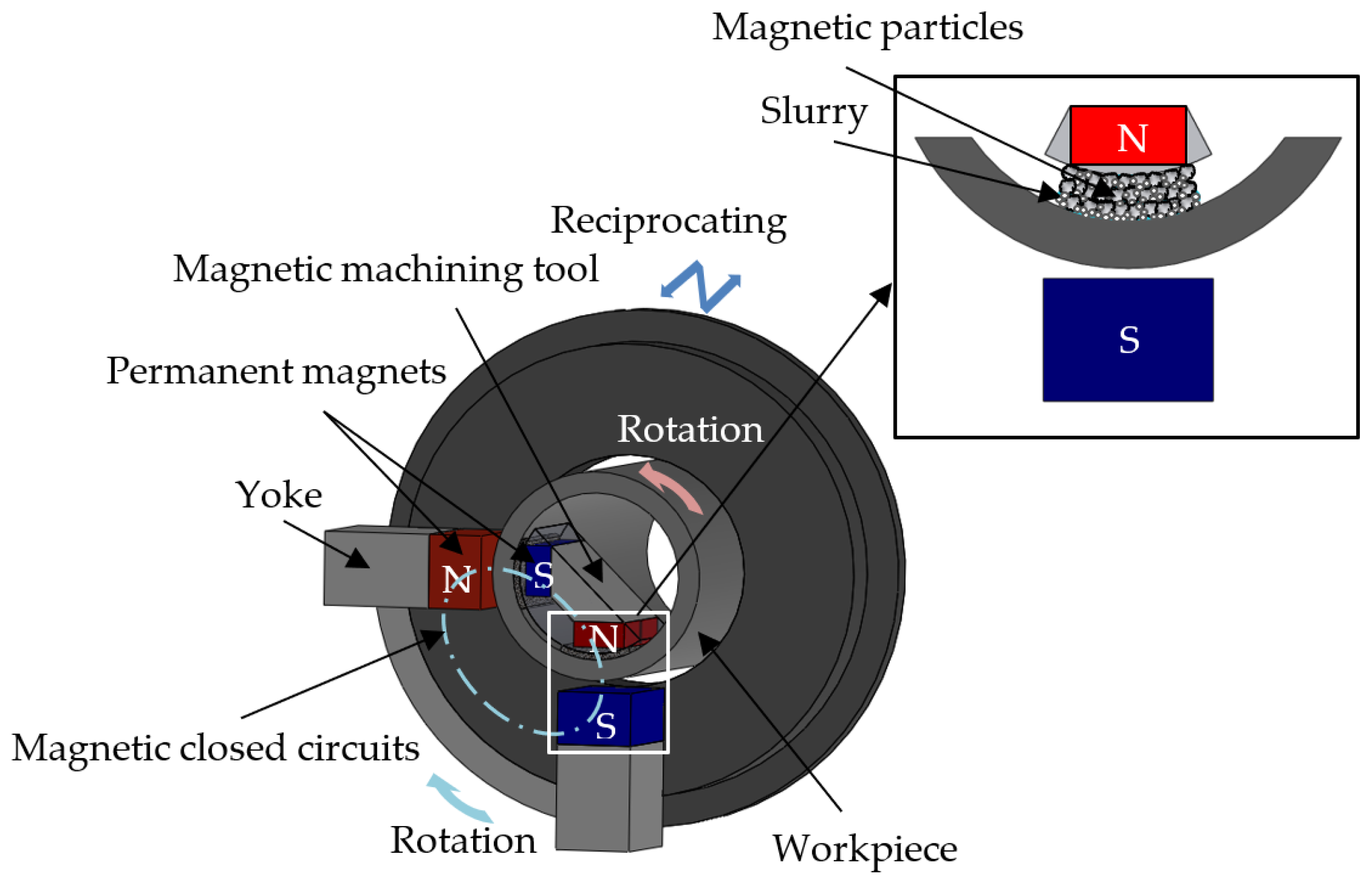
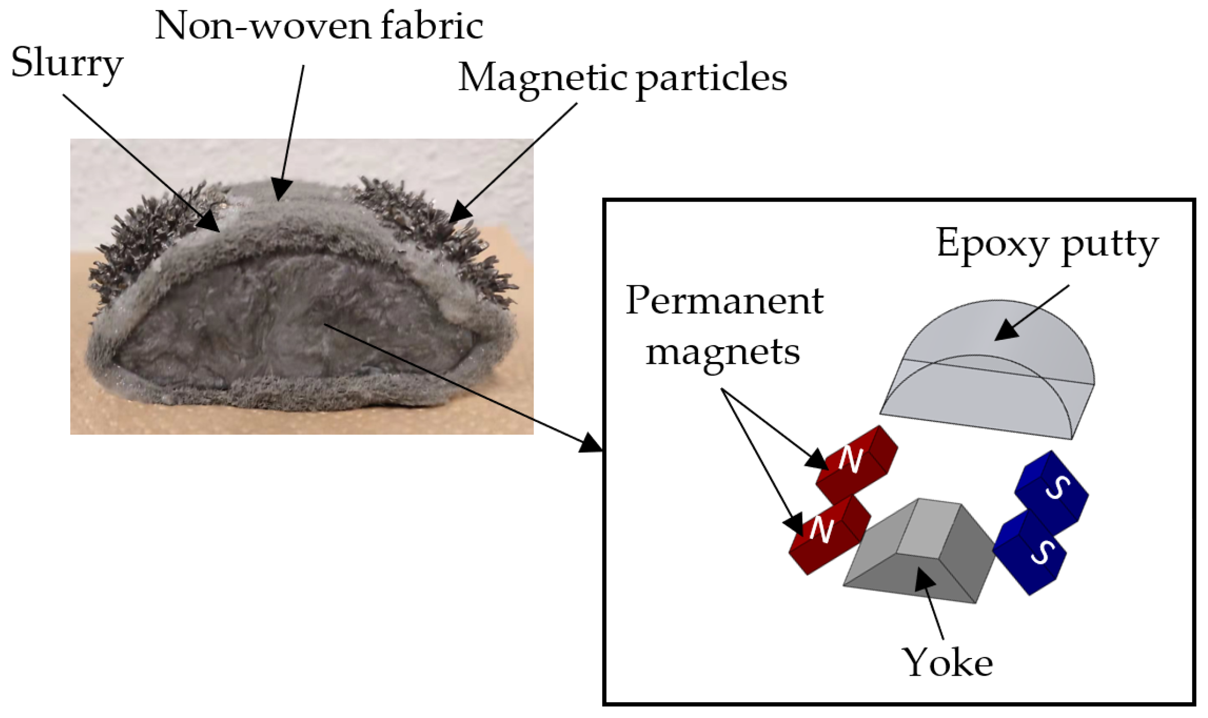
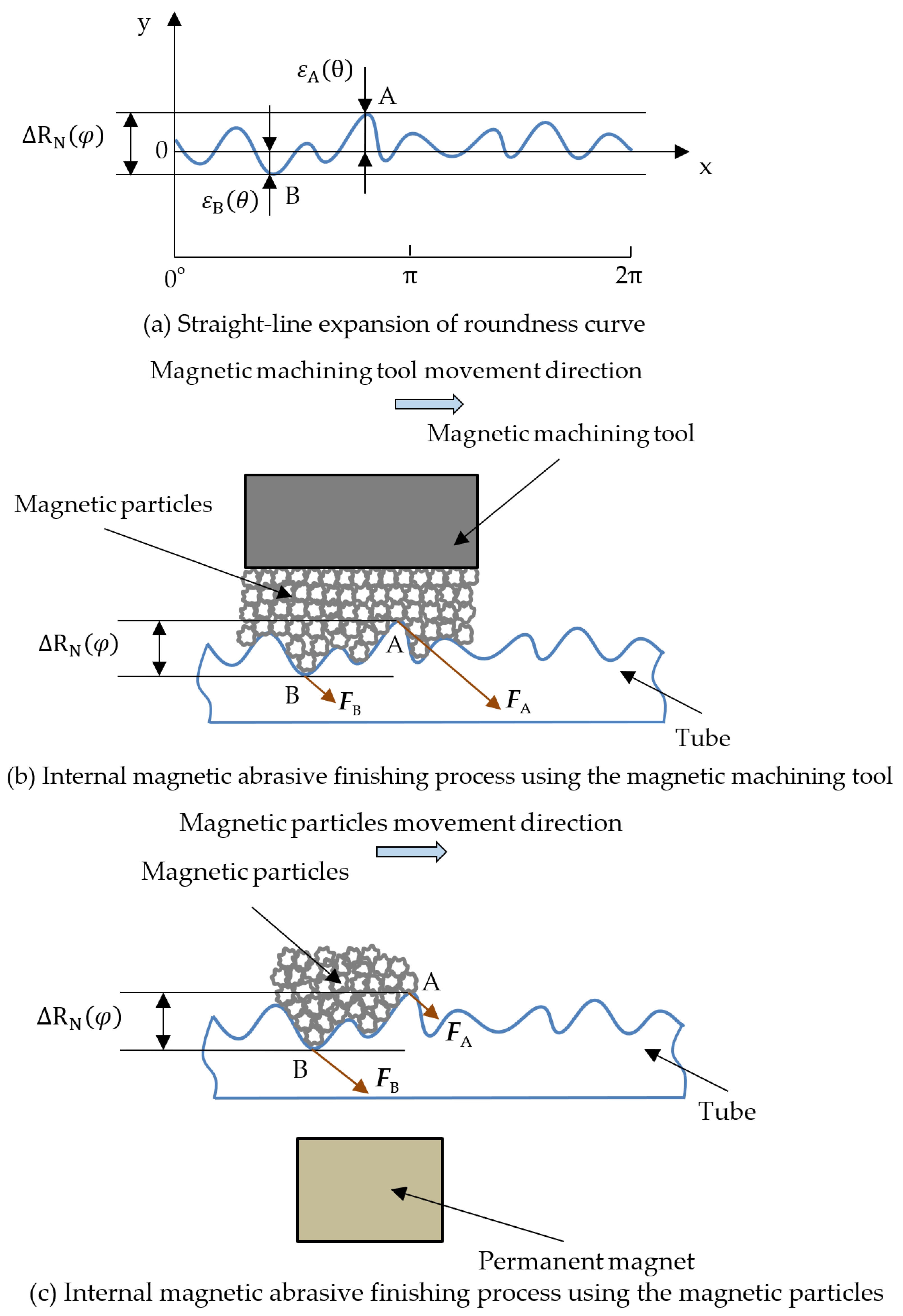
2. Processing Principle

Figure 1 shows a schematic of the internal magnetic abrasive finishing process using a magnetic machining tool. Figure 2 shows the structure of a magnetic machining tool. The magnetic machining tool was composed of two pairs of permanent magnets and a yoke and was wrapped with epoxy putty to conform to the shape of the tube’s internal surface. Furthermore, in order to prevent a collision, the magnetic machining tool was wrapped with non-woven fabric during processing. The magnetic particles were magnetically attracted to the surface of the magnetic machining tool. The magnetic machining tool inside the tube was attracted by the permanent magnets outside the tube, forming magnetic closed circuits that generated high magnetic force as a finishing force. When the magnetic machining tool rotated with the rotation of the permanent magnets, this resulted in relative movement between the workpiece and the magnetic particles. In order to achieve a high-quality surface, abrasive slurry was used; this was mixed with abrasive particles and water-soluble abrasive solution in a certain proportion. Therefore, the relative movement was indirectly transferred from the magnetic particles to the abrasive particles. Moreover, when the permanent magnets outside the tube were driven in the direction of the tube axis while rotating, that the high-precision finishing of the entire internal surface of the tube could be achieved.

3. Mechanism of Roundness Improvement

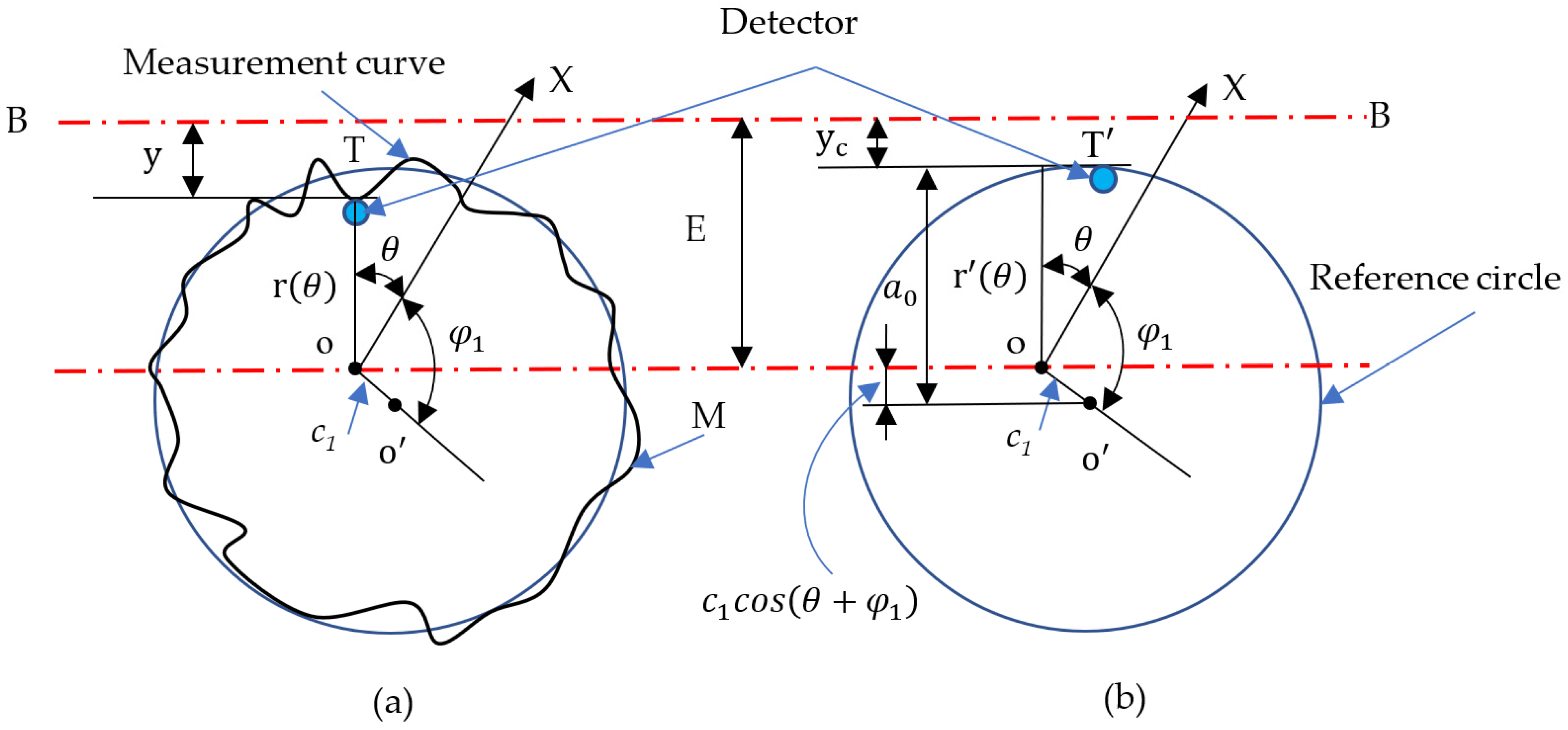
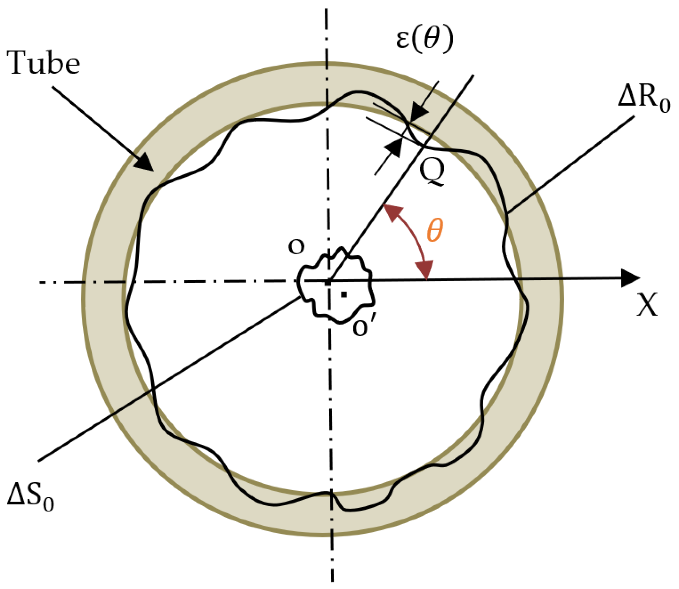
3.1. Fourier Series Expression of Roundness Curve

In this research, the roundness curve expression was derived using the principle of roundness measurement by the assumed center method [23].
Figure 3 shows the schematic of the internal surface roundness measurement by the assumed center method. Point o is the assumed center—that is, the center of rotation during measurement—and the detector is in contact with the internal surface of the tube. Vibration values of various angles are obtained during rotation, resulting in the roundness value including the influence of eccentricity. As shown in Figure 3a, θ is the angle of rotation, and r ( θ ) is the variable about angle θ . M is the roundness curve. Relative to the reference circle, the vibration value of each angle is positive when it is inside the reference circle and negative when it is outside. In the case of measuring the roundness of the reference circle, as shown in Figure 3b, the eccentricity between the center o and the measuring center o is c 1 , angle φ 1 is the phase, the radius of the reference circle is a 0 , and the radius variable r ( θ ) is expressed as:
r ( θ ) = a 0 c 1 cos ( θ + φ 1 )
Setting the position when the indicator value y c of the detector is 0 as B-B, the distance to the measuring center is expressed by E. Then, the pointer reading y c ( θ ) about angle θ described by the cosine curve can be obtained by:
y c ( θ ) = E r ( θ ) = ( E a 0 ) + c 1 cos ( θ + φ 1 )
Moreover, as shown in Figure 3a, r(θ) is a periodic function with a period of 2π and the Fourier series expansion is given by:
r ( θ ) = a 0 + a 1   cos θ + a 2   cos 2 θ + a 3   cos 3 θ + + a n   cos n θ + + b 1   sin θ + b 2   sin 2 θ + b 3   sin 3 θ + + b n   sin n θ + = a 0 + c 1 cos ( θ + φ 1 ) + c 2 cos ( 2 θ + φ 2 ) + + c n cos ( n θ + φ n ) +
where, a n and b n are constants.
Then, the value y for the detector is expressed as:
y ( θ ) = E r ( θ ) = ( E a 0 ) c 1 cos ( θ + φ 1 ) n = 2 c n cos ( n θ + φ n )
Comparing Equation (2) with Equation (4), the first term ( E a 0 ) on the right is a constant which represents the size of the reference circle. The second term is the eccentricity of the assumed center from the reference circle.
Substituting Equation (3) into Equation (4) to obtain indicated value y ( θ ) is achieved by:
y ( θ ) = ( E a 0 ) a 1   cos θ ( a 2   cos 2 θ + + a n   cos n θ + ) b 1   sin θ ( b 2   sin 2 θ + + b n   sin n θ + )
where ( E a 0 ) is a constant, ( a 1   cos θ + b 1   sin θ ) is the eccentricity of the assumed center from the reference circle, and ( a 2   cos 2 θ + b 2   sin 2 θ + + a n   cos n θ + b n   sin n θ + ) is the expression of roundness. Therefore, the roundness expression expanded by Fourier series is obtained by:
R ( θ ) = a 2   cos 2 θ + b 2   sin 2 θ + + a n   cos n θ + b n   sin n θ + = n = 2 c n cos ( n θ + φ n )

3.2. The Changing Process of Roundness

In this study, we mainly consider the roundness to be changed by the finishing force and eccentricity during clamping. As shown in Figure 4, the roundness curve and the vibration curve caused by the eccentricity of the internal surface of the tube are R 0 ( θ ) and S 0 ( θ ) , respectively, and given by [24,25]:
R 0 ( θ ) = n = 2 A n cos ( n θ + φ n ) S 0 ( θ ) = m = 1 B m   cos   ( m θ + β m ) + S ( θ ) }
where A n and B m are amplitude, φ n and β m are phase angle, S 0 ( θ ) is the random variation of the rotation axis, and θ is the angle of rotation.
The sum of Equation (7) plus the eccentricity A 1 cos ( θ + φ 1 ) when the tube is clamped, A 1 is amplitude, and φ 1 is the phase angle, the vibration amount ε ( θ ) of the internal surface of the tube can be expressed as:
ε ( θ ) = n = 2 A n cos ( n θ + φ n ) + A 1 cos ( θ + φ 1 ) + m = 1 B m   cos   ( m θ + β m ) + S ( θ )
Moreover, the vibration removal ε w ( θ ) after processing at point Q on the internal surface of the tube is given by:
ε w ( θ ) = C m [ K ε ( θ ) + P ]
The value of ε w ( θ ) is positive on the inside of the tube and negative on the outside. When P is the standard setting of finishing force, K is the proportional coefficient between the finishing force and the change in the surface of the tube, and C m is the processing quantity coefficient (which is related to the type and size of magnetic particles and abrasive materials, the presence and type of abrasive fluid, and the material of the workpiece, etc.).
When the tube and the magnetic machining tool relative rotate one circle, the change in the internal surface is calculated by:
ε ( φ + 2 π ) = ε ( φ ) C m K ε ( φ ) = ( 1 C m K ) ε ( φ ) ( 0 φ 2 π )
Then, the roundness curve R N ( θ ) ( θ = φ + 2 N π ) after N turns is given by:
R N ( θ ) = R N ( φ + 2 N π ) = R N ( φ ) = R N 1 ( φ ) C m [ K   ε { φ + 2 ( N 1 ) π } + P ] + L N
where L N is the correction value of the reference circle (zero value) and N = 1, 2, 3, …… The roundness R N ( φ ) after N rotations is obtained by arranging the left and right sides of the above equation in the form:
R N ( φ ) = R 0 ( φ ) C m K i = 1 N ε [ φ + 2 ( i 1 ) π ] C m   N   P + i = 1 N L i
where C m   N   P and i = 1 N L i are the reference circle position of the specified roundness curve, which has no direct relationship with roundness, so the roundness curve R N ( φ ) can be calculated thus:
R N ( φ ) = R 0 ( φ ) C m K i = 1 N ε [ φ + 2 ( i 1 ) π ]
Moreover, substituting Equation (8) into Equation (13) to obtain the roundness R N ( φ ) is expressed as:
R N ( φ ) = ( 1 C m K ) N n = 2 A n cos ( n φ + φ n ) C m K i = 0 N 1 ( 1 C m K ) N i 1 [ A 1 cos ( φ + φ 1 ) + m = 1 B m cos ( m φ + β m ) + S ( φ + 2 i π ) ]
As shown in Equation (14), the first item is the influence of the roundness curve before finishing, the second term concerns the influence of eccentricity during clamping, the third term is the influence of periodic variations due to eccentricity, and the fourth term is the effect of the randomness of eccentricity.

3.3. Analysis of the Influencing Factors of Roundness Improvement

3.3.1. Discussion on the Influence of Eccentricity

If the parameters in Equation (14) are determined, the roundness value can be calculated. However, this is difficult because the process involves the repeated processing of the same point to achieve the purpose of finishing, so it can be analyzed by considering N to be infinite. That is, each parameter can be analyzed by R ( φ ) .
We know that | 1 C m K | < 1 —that is [ ( 1 C m K ) N ] N = 0 . This is obtained by:
[ C m K i = 0 N 1 ( 1 C m K ) N i 1 ] N = 1
When N , it is obtained by:
( 1 C m K ) N n = 2 A n cos ( n φ + φ n ) = 0
Therefore, in this case, the influence of the roundness curve before machining can be ignored. Then, the equipment is expressed as:
C m K i = 0 N 1 ( 1 C m K ) N i 1 [ A 1 cos ( φ + φ 1 ) + m = 1 B m cos ( m φ + β m ) ] = A 1 cos ( φ + φ 1 ) m = 1 B m cos ( m φ + β m )
From Equation (17), it can be seen that the influence of the eccentricity during clamping and the periodic variation caused by the eccentricity is proportional. If A 1 = 0 , the influence of eccentricity can be eliminated, and then B m = 0 , which can be achieved by clamping at both ends.
Moreover, for random item S ( φ + 2 i π ) , if the maximum absolute value is assumed to be S m , then it is obtained by:
| C m K i = 0 N 1 ( 1 C m K ) N i 1 S ( φ + 2 i π ) | < C m K i = 0 N 1 ( 1 C m K ) N i 1 S m = [ 1 ( 1 C m K ) N ] S m
when N , the right side of the above formula gradually approaches S m , but does not exceed S m . The value of S m is very small. If we assume a value of 0.1, then the effect of the random variable is less than 0.1. Therefore, the influence of eccentricity can be ignored.

3.3.2. Discussion on the Influence of Finishing Force

Furthermore, it can be seen from Equation (9) that the change in vibration is proportional to K—that is, it is also proportional to the finishing force. Figure 5 shows the analysis of the roundness improvement. Figure 5a is a straight-line expansion of the roundness curve. According to the evaluation method of roundness [26], it can be seen that when the ε A ( θ ) becomes smaller, it is beneficial to improve the roundness, while when the absolute value of ε B ( θ ) becomes larger, it is unfavorable to improve the roundness. Therefore, as shown in Figure 5b, in the case of internal magnetic abrasive finishing process using the magnetic machining tool, because the magnetic particles are attracted to the surface of the magnetic machining tool by the magnetic force and the magnetic machining tool and the magnetic pole outside the tube produce pressure on the magnetic particles, the magnetic particles form a semi-fixed magnetic brush, resulting in the finishing force mainly being concentrated at point A and little finishing force acting on point B, which can improve the roundness. As shown in Figure 5c, in the case of using magnetic particles, point B is closer to the permanent magnet than point A, and the finishing force is concentrated at point B, so the roundness cannot be improved [27]. Therefore, it is clarified why the internal magnetic abrasive finishing process using the magnetic machining tool is effective in improving the roundness theoretically.

4. The Experimental Verification of SUS304 Stainless Steel Tube

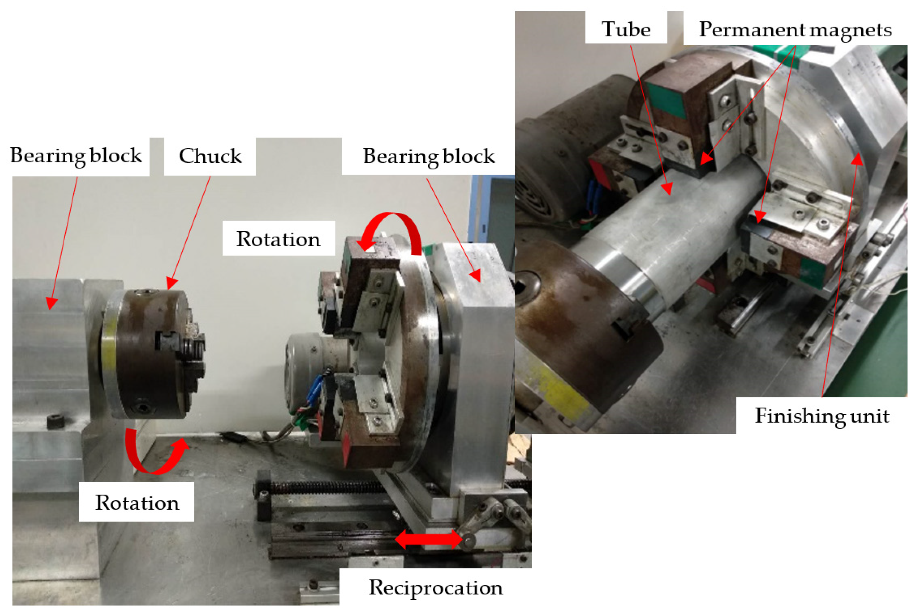
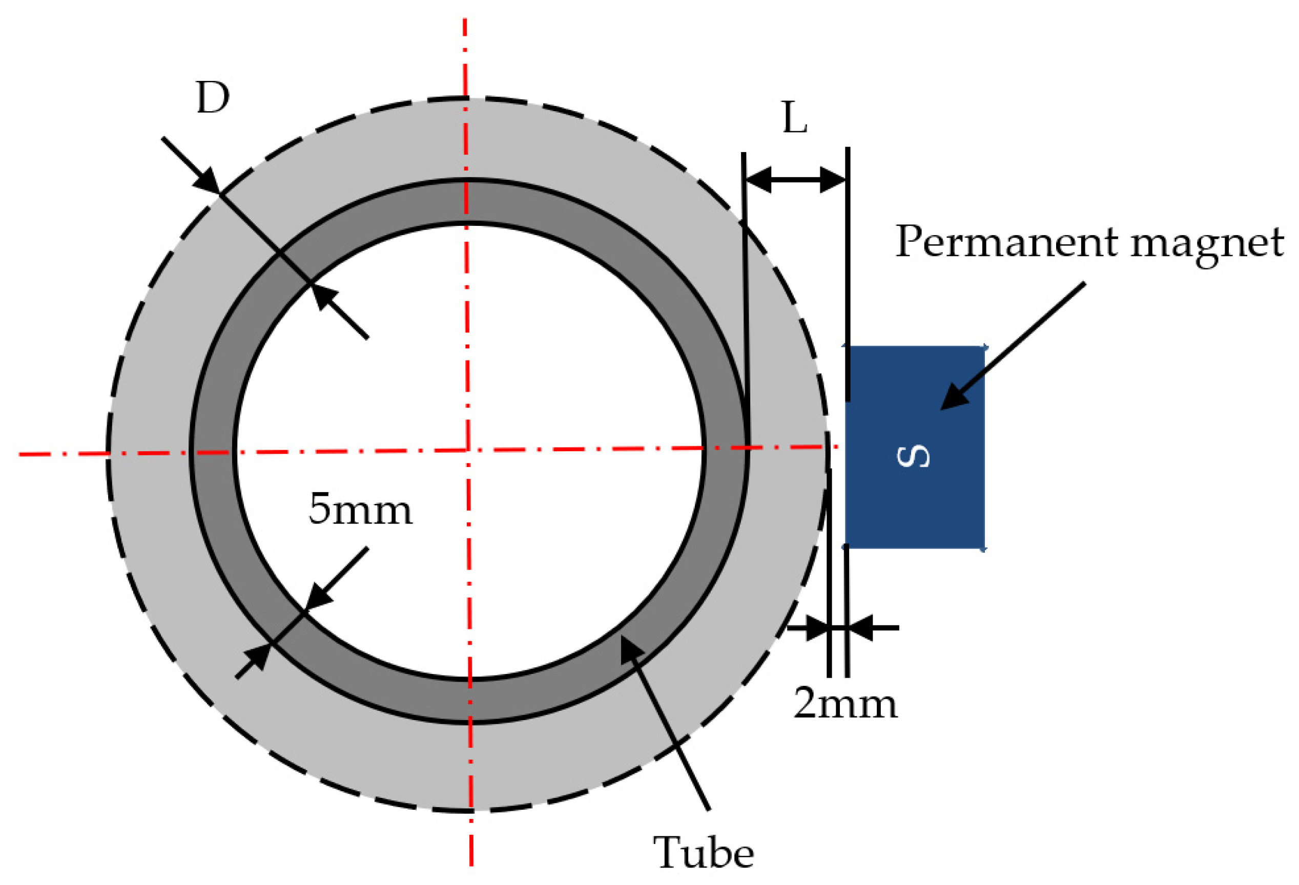
4.1. Experimental Setup and Conditions

Figure 6 shows an external view of the experimental setup for the internal magnetic abrasive finishing process using the magnetic machining tool. SUS304 stainless steel tube, as a workpiece, was clamped in the chuck and the other side was fixed with the tailstock and the top. The finishing unit, consisting of four permanent magnets (50 × 35 × 26 mm) attached inside a yoke, was set up on the reciprocating table. The permanent magnets were arranged N-S-S-N at a 90° interval toward the tube center, and the magnets’ distribution was flexible for various tube diameters. An adequate finishing force could be obtained because of the placement of the magnetic machining tool inside the tube. Moreover, the finishing unit could be driven in the direction of the tube axis during rotation. At the same time, the workpiece also rotated to generate relative movement and then realize the finishing of the internal surface of the tube.
The experimental conditions are shown in Table 1. The conditions of each experiment included the rotational speed of the tube and finishing unit. The reciprocating speed of the finishing units were the same, and the magnetic particles were all electrolytic iron particles 1680 µm in mean diameter. The roughness of the internal surface was improved by using abrasive particles with a gradually reduced particle size. After each stage of processing (15 min), the roughness, roundness, and weight of the workpiece were measured. Among these, the roughness was measured by a surface roughness meter (SURFPAK-PRO produced by Mitutoyo, Kawasaki, Japan), the internal surface roundness was measured by a roundness measuring instrument (RONDCOM 40C produced by TOKYO SEIMITSU, Hachioji, Japan), and the weight of the workpiece was measured using the balance PR8001 (SHIMADZU, Kyoto, Japan, minimum weighing unit: 0.1 g). Furthermore, as shown in Figure 7, in the experiment the distance L between the tube and the permanent magnet of the finishing unit was adjusted to 12 mm, 22 mm, and 32 mm, respectively. If the finishing gap (the distance between the permanent magnet of the finishing unit and the tube) is assumed to be 2 mm, the thickness of tube D will be equivalent to 10 mm, 20 mm, and 30 mm, respectively.

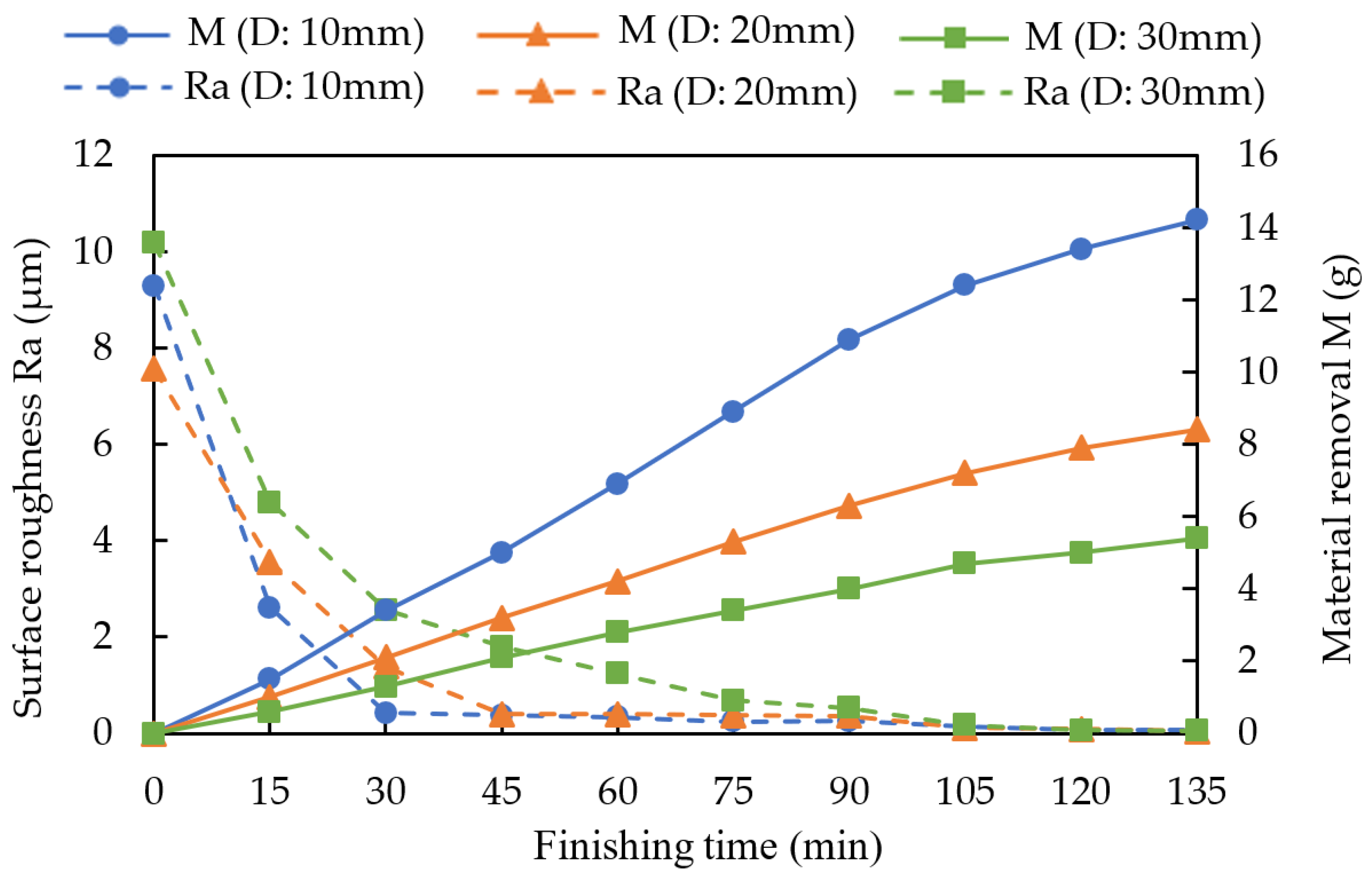
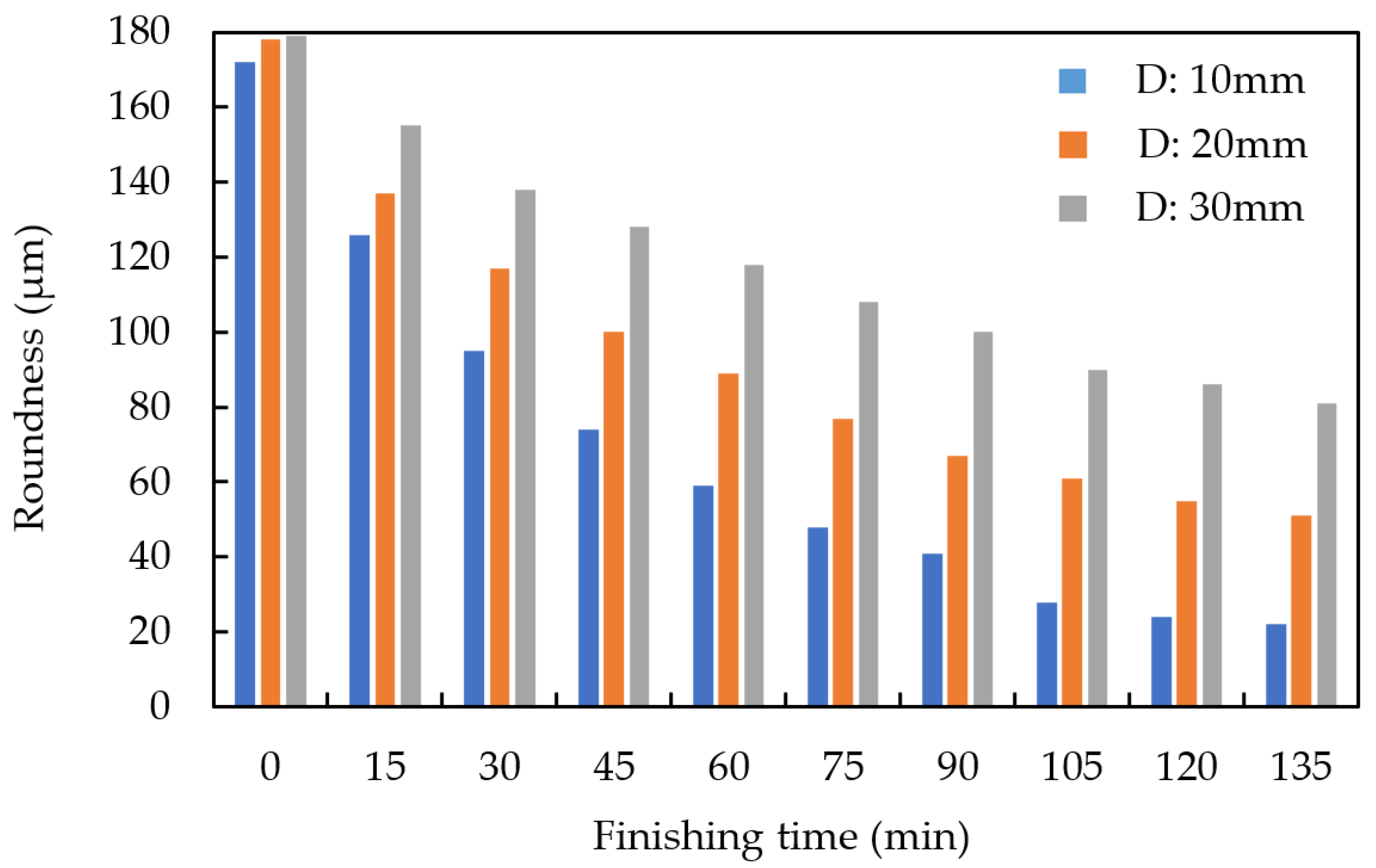
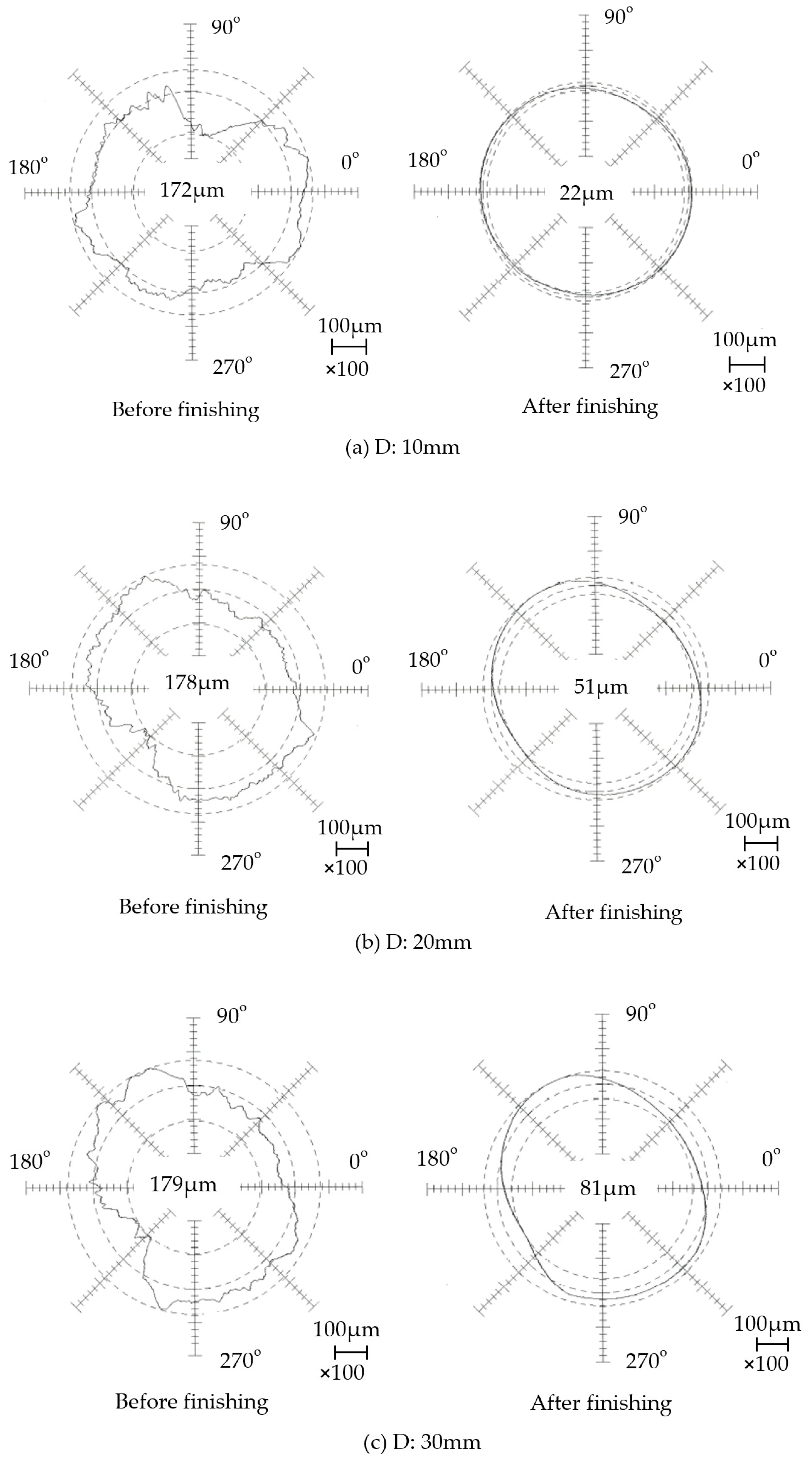
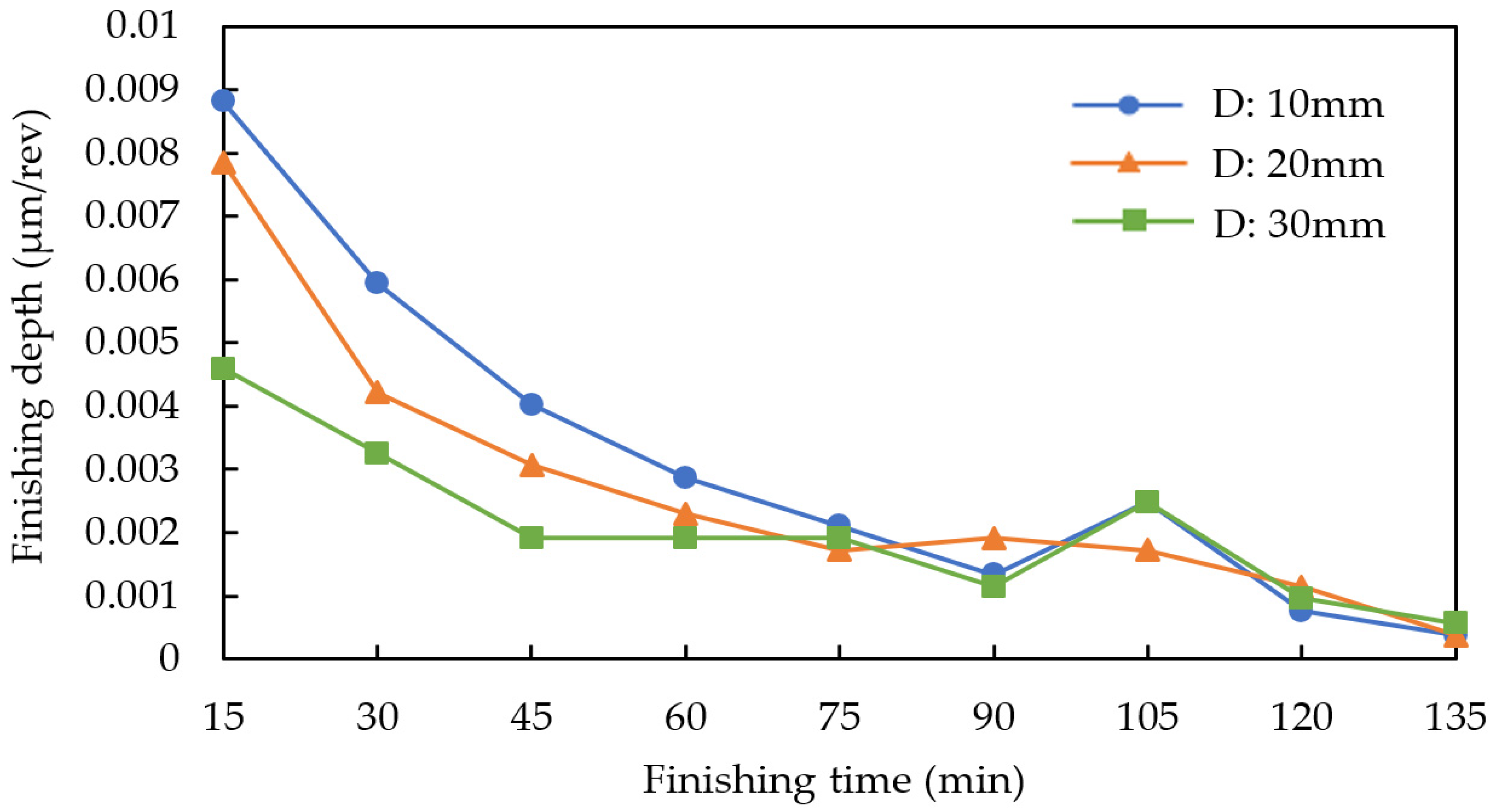
4.2. Experimental Results and Discussion

Figure 8 shows the changes in surface roughness and material removal with finishing time. It can be seen that, because the diameters of the magnetic particles and the abrasives used in the experiment were the same, the surface roughness after finishing was almost the same. As the thickness of the tube increased, the finishing force decreased, meaning that the amount of material removed decreased. For different tube thicknesses, the amount of material removed was 14.2 g in the case of 10 mm, 8.4 g in the case of 20 mm, and 5.4 g in the case of 30 mm. In addition, it was concluded that the internal magnetic abrasive finishing process using the magnetic machining tool process could finish thick tubes with thicknesses ranging from 10 mm to 30 mm.
Figure 9 shows the changes in roundness with finishing time. It can be seen that this process can improve the roundness of thick tubes whose thickness is from 10 mm to 30 mm. As the thickness of the tube increased, the value of the roundness improvement decreased. For different tube thicknesses, the value of roundness improvement was 150 µm in the case of 10 mm, 127 µm in the case of 20 mm, and 98 µm in the case of 30 mm.
Figure 10 shows the roundness profiles of the internal surface of the tube before and after finishing. For different tube thicknesses, the roundness was improved from 172 µm to 22 µm in the case of 10 mm, from 178 µm to 51 µm in the case of 20 mm, and from 179 µm to 81 µm in the case of 30 mm. It can be seen from the experimental results that as the thickness of the tube decreased, the finishing force of the radial direction of the tube increased. Consequently, it was concluded that the internal magnetic abrasive finishing process using the magnetic machining tool was effective for improving the roundness of thick tubes with thicknesses from 10 mm to 30 mm.

4.3. Confirmation of Mechanism Analysis Results and Experimental Results

When the influence of eccentricity during clamping and random items on the roundness curve is ignored, Equation (14) can be written as:
R N ( φ ) = ( 1 C m K ) N n = 2 A n cos ( n φ + φ n )
This is obtained by:
R 46980 ( φ ) / R 0 ( φ ) = ( 1 C m K ) 46980
In the case of thickness of the tube being 10 mm, R 46980 ( φ ) / R 0 ( φ ) is 0.1279. In the case of thickness of the tube being 20 mm, R 46980 ( φ ) / R 0 ( φ ) is 0.2865. Furthermore, in the case of the thickness of the tube being 30 mm, R 46980 ( φ ) / R 0 ( φ ) is 0.4525. It can be seen from the calculation results that as the thickness of the tube increased, the value of K decreased—that is, the finishing force decreased. Therefore, it can be concluded that as the thickness of the tube increased, the roundness improvement decreased.
Figure 11 shows the changes in finishing depth per revolution. When the thickness of the tube became smaller, the processing depth per revolution became larger. As the finishing time became longer, the changes in finishing depth per revolution became smaller. For the processing interval of 0–15 min, in the case of a tube thickness of 10 mm, the change in the finishing depth per revolution was 0.008812 µm; in the case of a tube thickness of 20 mm, the change in the finishing depth per revolution was 0.007854 µm; and in the case of a tube thickness of 30 mm, the change in the finishing depth per revolution was 0.004598 µm. In the processing interval of 120–135 min, in the case of a tube thickness of 10 mm, the change in the finishing depth per revolution was 0.000383 µm; in the case of a tube thickness of 20 mm, the change in the finishing depth per revolution was 0.000383 µm; and in the case of a tube thickness of 30 mm, the change in the finishing depth per revolution was 0.000575 µm.

5. Conclusions

This research studies the mechanism of improving the roundness of an SUS304 stainless steel tube by an internal magnetic abrasive finishing process using a magnetic machining tool. The main conclusions are summarized as follows:
  • The mechanism of roundness improvement was analyzed theoretically. The roundness curve expression was derived using the principle of roundness measurement by assumed center method and the expression of the roundness curve expanded by Fourier series was obtained.
  • The factors influencing roundness improvement—eccentricity and finishing force—were discussed. When the workpiece is clamped at both ends, the influence of eccentricity can be ignored. Moreover, it is clear that the magnetic abrasive finishing process using the magnetic machining tool was effective in improving the roundness of the internal surface of the thick tubes.
  • Confirming the mechanism analysis results and the experimental results, it can be concluded that the internal magnetic abrasive finishing process using the magnetic machining tool was effective for improving the roundness of thick tubes with a thickness from 10 mm to 30 mm. As the thickness of the tube increased, the finishing force decreased, causing the roundness improvement to decrease. For different tube thicknesses, the roundness was improved from 172 µm to 22 µm in the case of 10 mm, from 178 µm to 51 µm in the case of 20 mm, and from 179 µm to 81 µm in the case of 30 mm.

Author Contributions

Conceptualization, J.L. and Y.Z.; Data curation, J.L.; Formal analysis, J.L.; Funding acquisition, Y.Z.; Investigation, J.L. and Y.Z.; Methodology, J.L. and Y.Z.; Project administration, Y.Z.; Validation, J.L. and Y.Z.; Writing—original draft, J.L. and Y.Z.; Writing—review and editing, J.L. and Y.Z. All authors have read and agreed to the published version of the manuscript.

Funding

This research received no external funding.

Institutional Review Board Statement

Not applicable.

Informed Consent Statement

Not applicable.

Data Availability Statement

The data presented in this study are available on request from the corresponding author.

Conflicts of Interest

The authors declare no conflict of interest.

References

  1. Zou, Y.H.; Shinmura, T.; Wang, F. Study on a magnetic deburring method by the application of the plane magnetic abrasive machining process. Adv. Mater. Res. 2009, 76–78, 276–281. [Google Scholar] [CrossRef]
  2. Jain, V.K. Magnetic field assisted abrasive based micro-/nano-finishing. J. Mater. Process. Technol. 2009, 209, 6022–6038. [Google Scholar] [CrossRef]
  3. Yamaguchi, H.; Shinmura, T. Internal finishing process for alumina ceramic components by a magnetic field assisted finishing process. Precis. Eng. 2004, 28, 135–142. [Google Scholar] [CrossRef]
  4. Shinmura, T.; Takazawa, K.; Hatano, E.; Matsunaga, M.; Matsuo, T. Study on magnetic abrasive finishing. Ann. CIRP 1990, 39, 325–328. [Google Scholar] [CrossRef]
  5. Shinmura, T.; Yamaguchi, H. Study on a new internal finishing process by the application of magnetic abrasive machining: Internal finishing of stainless steel tube and clean gas bomb. JSME Int. J. Ser. C 1995, 38, 798–804. [Google Scholar] [CrossRef]
  6. Yamaguchi, H.; Shinmura, T.; Kobayashi, A. Development of an internal magnetic abrasive finishing process for nonferromagnetic complex shaped tubes. JSME Int. J. Ser. C 2001, 44, 275–281. [Google Scholar] [CrossRef] [Green Version]
  7. Kang, J.; Yamaguchi, H. Internal finishing of capillary tubes by magnetic abrasive finishing using a multiple pole-tip system. Precis. Eng. 2012, 36, 510–516. [Google Scholar] [CrossRef]
  8. Kang, J.; George, A.; Yamaguchi, H. High-speed internal finishing of capillary tubes by magnetic abrasive finishing. Procedia CIRP 2012, 1, 414–418. [Google Scholar] [CrossRef] [Green Version]
  9. Jha, S.; Jain, V.K. Design and development of the magnetorheological abrasive flow finishing (MRAFF) process. Int. J. Mach. Tools Manuf. 2004, 44, 1019–1029. [Google Scholar] [CrossRef]
  10. Jha, S.; Jain, V.K.; Komanduri, R. Effect of extrusion pressure and number of finishing cycles on surface roughness in magnetorheological abrasive flow finishing (MRAFF) process. Int. J. Adv. Manuf. Technol. 2007, 33, 725–729. [Google Scholar] [CrossRef]
  11. Das, M.; Jain, V.K.; Ghoshdastidar, P.S. Analysis of magnetorheological abrasive flow finishing (MRAFF) process. Int. J. Adv. Manuf. Technol. 2007, 38, 613–621. [Google Scholar] [CrossRef]
  12. Kim, J. Polishing of ultra-clean inner surfaces using magnetic force. Int. J. Adv. Manuf. Technol. 2003, 21, 91–97. [Google Scholar] [CrossRef]
  13. Kim, J.; Choi, M. Stochastic approach to experimental analysis of cylindrical lapping process. Int. J. Mach. Tools Manuf. 1995, 35, 51–59. [Google Scholar] [CrossRef]
  14. Chen, K.Y.; Tu, T.Y.; Fan, Y.H.; Wang, A.C.; Fu, P.K. Study on the polishing characteristics of the rotating cylinder-based magnetic gel abrasive finishing. Processes 2021, 9, 1794. [Google Scholar] [CrossRef]
  15. Cheng, K.C.; Chen, K.Y.; Tsui, H.P.; Wang, A.C. Characteristics of the polishing effects for the stainless tubes in magnetic finishing with gel abrasive. Processes 2021, 9, 1561. [Google Scholar] [CrossRef]
  16. Zou, Y.H.; Shinmura, T. A study on the magnetic field assisted machining process for internal finishing using a magnetic machining jig. Key Eng. Mater. 2004, 257–258, 505–510. [Google Scholar] [CrossRef]
  17. Muhamad, M.R.; Zou, Y.H.; Sugiyama, H. Development of a new internal finishing of tube by magnetic abrasive finishing process combined with electrochemical machining. Int. J. Mech. Eng. Appl. 2015, 3, 22–29. [Google Scholar] [CrossRef] [Green Version]
  18. González, H.; Calleja, A.; Pereira, O.; Ortega, N.; López de Lacalle, L.N.; Barton, M. Super abrasive machining of integral rotary components using grinding flank tools. Metals 2018, 8, 24. [Google Scholar] [CrossRef]
  19. Rodriguez, A.; López de Lacalle, L.N.; Pereira1, O.; Fernandez, A.; Ayesta, I. Isotropic finishing of austempered iron casting cylindrical parts by roller burnishing. Int. J. Adv. Manuf. Technol. 2020, 110, 753–761. [Google Scholar] [CrossRef]
  20. Yamaguchi, H.; Shinmura, T. Study of an internal magnetic abrasive finishing using a pole rotation system: Discussion of the characteristic abrasive behavior. Precis. Eng. 2000, 24, 237–244. [Google Scholar] [CrossRef]
  21. Zou, Y.H.; Shinmura, T. Mechanism of a magnetic field assisted finishing process using a magnetic machining jig. Key Eng. Mater. 2007, 339, 106–113. [Google Scholar] [CrossRef]
  22. Zou, Y.H.; Shinmura, T. Development of magnetic field assisted machining process using magnetic machining jig. JSME Int. J. Ser. C 2002, 68, 233–239. (In Japanese) [Google Scholar] [CrossRef] [Green Version]
  23. Nakata, K. Engineering Analysis: A Mathematical Approach for Engineers, 1st ed.; Ohm Press: Saitama, Japan, 1972; pp. 79–84. [Google Scholar]
  24. Shinmura, T.; Takazawa, K.; Hatano, E. Study on magnetic abrasive finishing: Rounding condition and its confirmation by experiment. Bull. Jpn. Soc. Precis. Eng. 1986, 52, 1598–1603. (In Japanese) [Google Scholar] [CrossRef]
  25. Shinmura, T.; Aizawa, T. Study on Internal Finishing of a Non-ferromagnetic Tubing by Magnetic Abrasive Machining Process. Bull. Jpn. Soc. Precis. Eng. 1989, 23, 37–41. (In Japanese) [Google Scholar]
  26. Nakano, K. Precision Shape Measurement Practice: Interpretation of Geometric Tolerances and Measurement of Geometric Deviations, 1st ed.; Kaibundo Publishing Co., Ltd.: Tokyo, Japan, 1992; pp. 61–63. [Google Scholar]
  27. Yamaguchi, H.; Shinmura, T. Study on a new internal finishing process by the application of magnetic abrasive machining: Discussion of the roundness. Bull. Jpn. Soc. Precis. Eng. 1996, 62, 1617–1621. (In Japanese) [Google Scholar] [CrossRef]
Figure 1. Schematic of the internal magnetic abrasive finishing process using magnetic machining tool.
Machines 10 00112 g001
Figure 2. Structure of the magnetic machining tool.
Machines 10 00112 g002
Figure 3. Schematic of internal surface roundness measurement by the assumed center method. (a) By the measured roundness curve, (b) By the reference circle.
Machines 10 00112 g003
Figure 4. Analysis of the changing process of roundness curve.
Machines 10 00112 g004
Figure 5. Analysis of roundness improvement.
Machines 10 00112 g005
Figure 6. External view of the experimental setup.
Machines 10 00112 g006
Figure 7. The relationship between the distance between the poles and the thickness of the tube.
Machines 10 00112 g007
Figure 8. Changes in material removal and surface roughness with finishing time.
Machines 10 00112 g008
Figure 9. Changes in roundness with finishing time.
Machines 10 00112 g009
Figure 10. Roundness profiles of the internal surface of the tube before and after finishing.
Machines 10 00112 g010
Figure 11. Changes in finishing depth per revolution.
Machines 10 00112 g011
Table 1. Experimental conditions.
ParametersConditions
WorkpieceSUS304 stainless steel tube Ø89.1 × 79.1 × 200 mm
Rotational speed: 162 min−1
Magnetic machining toolMagnet: Nd-Fe-B rare earth permanent magnet
Yoke: SS400 steel
Molding material: Polymer
Finishing unitMagnet: Ferrite magnet 50 × 35 × 26 mm
Yoke: SS400 steel
Rotational speed: 186 min−1
Reciprocating speed: 1500 mm/min
Magnetic particlesElectrolytic iron particles: 1680 µm in mean dia., 24 g
Abrasive particles1st-stage (15 × 6 min)WA #400, 2.5 g
2nd-stage (15 min)WA #3000, 2.5 g
3rd-stage (15 min)WA #6000, 2.5 g
4th-stage (15 min)WA #10000, 2.5 g
Grinding fluidWater-soluble grinding fluid (SCP-23): 30 g
Thickness of tube (D)10 mm, 20 mm, 30 mm
Publisher’s Note: MDPI stays neutral with regard to jurisdictional claims in published maps and institutional affiliations.

