1. Introduction
Many investigations report an increasing number of people suffering from lower limb (LL) mobility loss (ML). Such ailments may be caused by a disease, an accident, surgery aftermath, or poor medical care, to name a few. Patients with ML usually undergo a rehabilitation process to prevent the damage from increasing and to try to recover mobility. Unfortunately, the rehabilitation process is sometimes inefficient due to the lack of proper equipment at rehabilitation centers [
1,
2,
3,
4,
5,
6,
7,
8].
People suffering from ML need to perform their activities of daily living (ADL), and they need to do so in a natural way, with natural motions, to prevent back disorders, obesity, cardiovascular diseases, muscle damage, depression, among other issues that deteriorate their health, both physical and mental, as well as their economy [
2,
3,
5,
7,
8].
Owing to current issues on rehabilitation, many experts have proposed LL assistance systems (LLAS), such as exoskeletons, to assist the rehabilitation process. An exoskeleton is a robotic structure designed to fasten to the human body,
Figure 1. Due to their functionality and practicality they have also been implemented in ADL [
1,
2,
3,
5,
9,
10].
Exoskeleton research began in the 1960s and, even though it has encountered some drawbacks, it is nowadays a wide field and has developed many branches, one being LLAS. Although there have been great advances, there are still many issues to be faced. Many LLAS researchers focus on: (1) control strategies that would allow the user to walk in a natural way; (2) motion-intention-prediction methods to detect in real time when the user wants to perform a particular motion and assist the user; and (3) developing a mechanical design that would take advantage of human biomechanics to spare/store energy during some percentage of the walking cycle and use or release it throughout the rest [
1,
2,
3,
4,
5,
8,
11,
12,
13,
14,
15,
16,
17,
18,
19,
20,
21].
Even though there are commercial LL exoskeletons (LLE), there are many others in development, many with a mechanical design since there are several improvements yet to be achieved.
Naik et al. [
23] developed a four degrees-of-freedom (DOF) LLE with a ratchet mechanism at the hip to restrict the motion in the sagittal plane, allowing the user to bear an extra 30 kg without extra effort.
Yap et al. [
24] designed an exosuit that stimulates upper limbs to assist lower limbs, based on the mutual entrainment principle,
Figure 2. Using the exoskeleton, they demonstrated that the angular displacement amplitude increases as the period of time decreases.
Auberger et al. [
25] developed a brace-like adjustable system to assist knee motion. It includes an elastic element that stores energy in the stance phase and releases it at the swing phase. The system provides high impedance during knee flexing and low impedance at extension. This is achieved with a hydraulic actuator, a plank mechanism, and two servo valves.
Xie et al. [
26] designed a flexible exoskeleton. The joints are actuated by an air cylinder that also varies joint stiffness and does not constrain the joints’ DOF.
Schmidt et al. [
27] developed a biarticular exoskeleton/exosuit,
Figure 3. It is biarticular since hip and knee are actuated by the same motor. It has elastic bands that store energy and release it to assist joint motion.
Shamaei et al. [
28] report a quasi-passive exoskeleton consisting of a pair of springs and a clutch. The clutch allows free motion in the swing phase. The springs are controlled by a latching mechanism. One stores energy at load acceptance and the other during knee flexion.
Zhou et al. [
29] designed an LLE that includes springs for gravity compensation. Springs are connected at the hip and knee joints to generate assistance torque. It was determined that, for walking cycles of between 3 and 8 s, torque decreases up to 84% at the hip and 69% at the knee. However, as the system compensates only for gravity, for shorter walking cycles springs’ efficiency is reduced.
Zhao et al. [
30] developed an exosuit for knee assistance. It has two twisted string actuators (TSA) and steel cord artificial muscles. The artificial muscles are achieved by combining a pair of Bowden cables, one at the thigh and the other at the calf, flexible straps to fasten to the user, and two nylon straps in series with the cables. The suit’s flexibility makes it possible not to modify the user’s motion since it does not constraint the LL’s DOF.
After researching, it is clear that there is a tendency to develop LLAS with means, such as elastic elements, clutches, passive or quasi-passive subsystems, among others, to minimize the energetic requirement of the system. We decided to tackle this issue, since diminishing energy consumption would yield to lighter systems, reduced metabolic cost to the user, and longer lasting batteries.
The next five sections of this article present the conceptual mechanical design (
Section 2), the mathematical modelling of the system (
Section 3), its control (
Section 4), its analysis (
Section 5) and the discussion of results and conclusions (
Section 6).
2. Mechanical Design
It has been demonstrated [
31] that, when analyzing the walking cycle, a major quantity of energy could be spared during the stance phase. Through that phase the body needs to be pushed forward. This can be achieved by assisting the knee and grounding the foot. Therefore, the hip and ankle joints could be set passive, although, obviously, it would make the upper body rather unstable for patients suffering from ML. Therefore, walking aids, such as crutches or walkers, would be necessary. Based on that idea, we designed an exoskeleton,
Figure 4, with a clutch and ratchet system (CRS),
Figure 5, at the hip, and a cam-like foot. The clutch would allow disconnecting the hip motor, which would be done in the stance phase, sparing energy; the ratchet would prevent the upper body from staggering in a static position without the need for crutches or walkers; the cam-like foot would allow the user to develop a smooth motion throughout the stance phase. The exoskeleton has one DOF at each hip and one at each knee, all of them in the sagittal plane.
The clutch-like mechanism, shown in the upper right image of
Figure 5, consists of two toothed disks: one, the input disk, fixed at the shaft that connects with the hip motor, and another one, the output disk, fixed at the shaft that connects with the exoskeleton’s thigh. The input disk, supported on a ball bearing with a sliding housing, has one translational DOF along the longitudinal axis of the hip motor’s shaft so that, when it moves towards the motor, it disengages from the output disk, setting the hip passive.
The ratchet mechanism, or stabilizer, (yellow mechanism in upper left image of
Figure 5) was designed as a crank mechanism; the lower left and right images of
Figure 5 show close-ups of the ratchet in lateral view. The curved element, seen in the upper left image of
Figure 5, works as the connecting rod and the thigh as the crank. Thus, when the thigh rotates, the connecting rod converts that rotation into vertical motion. The moving ratchet’s support has four ball bearings confined into the ratchet’s slider, as shown in the lower left image of
Figure 5. This allows the support to move in a vertical direction. This mechanism was designed to provide stability while the user is standing still, allowing the user to abandon walking aids when performing ADL in that position.
The ratchet needs to disengage in the swing phase and engage during the stance phase, or when the user is standing still, unlike the clutch that needs to disengage in the stance phase and engage in the swing phase. To perform this engagement-disengagement action both mechanisms need an actuator. We designed a synchronizer mechanism that would perform the engagement-disengagement action by engaging the clutch and at the same time disengaging the ratchet, and vice versa.
Figure 6 shows the kinematic chain of the synchronizer at the limit positions. The blue chain represents the mechanism at the beginning of stance phase (when the motor needs to disengage) and the red one at the end of it (when the motor needs to engage). The synchronizer is connected with the clutch with a rigid link, shown in the middle image of
Figure 5, and the ratchet connects with the synchronizer through physical contact with the synchronizer’s connecting rod.
The cam-like foot was designed like a cam with the ground as follower. To do so, the vertical distance between the ankle and the ground,
, according to
Figure 7, was determined as
where
according to [
32];
is the angular position of the cam;
, and are the angular positions of the thigh, leg and foot, respectively;
represent the cam’s base radii, defined as the radii of the smallest circle drawn tangent to the cam’s profile and concentric to its center of rotation;
according to [
32]; and
is the user’s total height and we set it equal to 1.7 m, the height of a standard human according to [
32].
The horizontal distance between the center of rotation of the cam and its contact point with the ground,
, is defined as [
33]
Finally, the radius from the center of rotation of the cam to its contact point with the ground,
, is computed by superposition of (1) and (2),
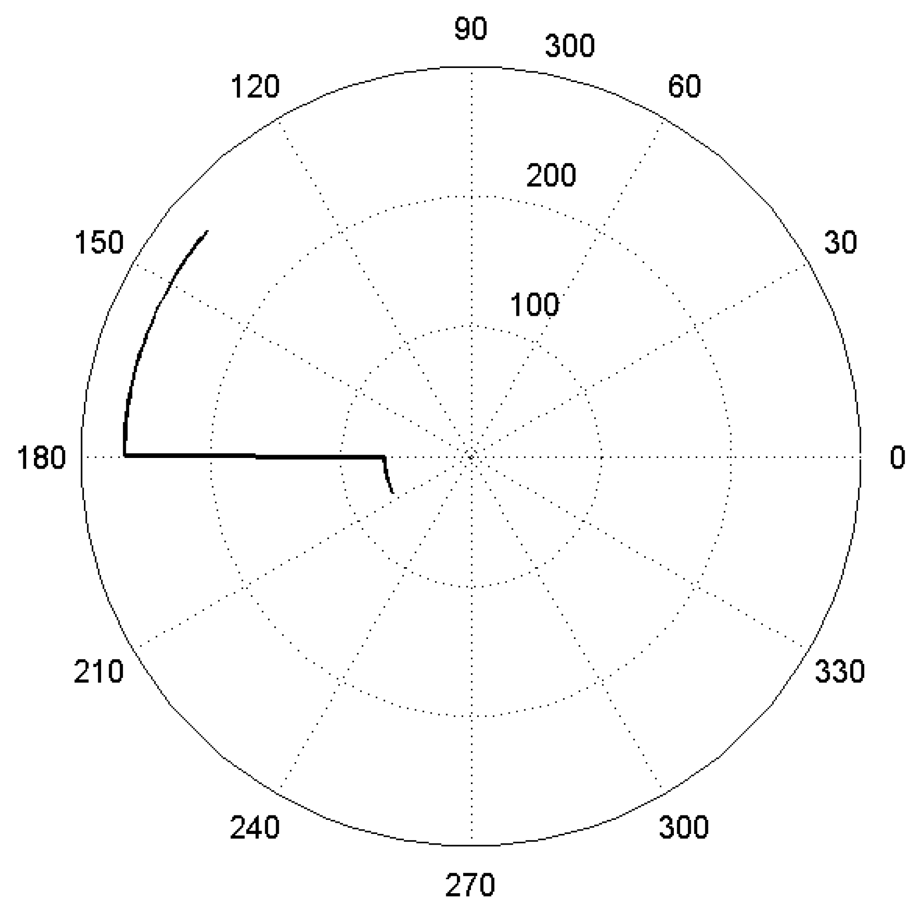
Figure 8 shows its plotting. Normally the profile in
Figure 8 would directly be considered as the cam’s profile, but since the follower, the ground, is fixed and the cam is moving, the leap in
Figure 8, when the foot is horizontal,
, is interpreted as a displacement of the cam’s rotation center, as shown in
Figure 9.
3. Mathematical Modelling
The LL can be depicted during the swing phase as a triple pendulum pivoted at the hip. Then,
and
coordinates of the thigh’s, leg’s and foot’s center of mass are given, according to
Figure 10, with the hip as the reference, by
and
where
, and are the coordinates for the thigh’s, leg’s and foot’s center of mass (com), respectively;
, and are the coordinates for the thigh’s, leg’s and foot’s com, respectively;
is the -th member’s total length;
is the -th member’s distance from its proximal joint to its com;
and are the sine and cosine of the -th member’s angular position, ;
;
;
; and
Given (3) through (8), according to the Lagrangian dynamic formulation [
34], the torques at the hip, knee and ankle are given by
where
is the total body mass,
is the total body height,
,
,
is the torque vector and
,
,
and
are the mass, Coriolis, centrifugal and gravity matrixes, respectively, given by
and
with
,
,
,
,
,
,
,
,
,
,
and
,
and
,
,
11,
and
Constants
through
result from using the anthropometric data from
Table 1, based on data from [
32]. Note that all parameters in
Table 1 are dimensionless since they are all proportions, for example, the segment’s mass/total mass is the mass of a segment, thigh, leg or foot, divided by the total body mass, since they are both measured in kg, the parameter is dimensionless.
Figure 11 shows the torques
,
,
and
, with
and
, developed at the hip joint. It can be seen that the Coriolis and centrifugal matrixes can be dismissed. Therefore, (9) can be approximated by
We determined the Pearson correlation factor between (9) and (10) and the results were 0.9767, 0.9707 and 0.9812 for , and , respectively.
Furthermore, we developed a model in ADAMS to represent the LL and ran a simulation to obtain the torques at the hip, knee and ankle and compared such results with those of (10).
Figure 12 shows this comparison and the difference between the torques computed with ADAMS and with (10).
Since the LLE is anthropomorphic, but with the leg and foot as a single element, with no ankle joint, the model that describes the required torques at the hip and knee to put in motion the mechanical structure,
, is analogical to (10) and is given by
where
and
are the mass and gravity matrix of the LLE, respectively, and are given by
and
with
,
,
,
and
,
and
, and represent the mass, inertia and proximal com of the LLE’s thigh, respectively,
, and represent the mass, inertia and proximal com of the LLE’s leg, respectively,
is the standard acceleration due to gravity.
During the stance phase, the LL acts as an inverted pendulum. Additionally, in the stance phase we are interested only in the knee torque, since there is no ankle joint and the hip will be passive. Therefore, the knee torque throughout this stance, to set in motion the LLE,
can be calculated analogically as (11), and is given by
where
and
,
and
,
and
is the mass of the upper body of the LLE.
Figure 13 shows the comparison of
computed with (12) and with ADAMS. The figure shows a difference at heel contact and a leap near the 7%, this is because, for simplicity, model (12) represents the LLE as an inverted triple pendulum, with the first pendulum being the foot, then the leg, and then the thigh. Nonetheless, from 0% to
7% of the walking cycle it is an inverted double pendulum, since the toes are off the ground, making the leg the first pendulum. From this, and from
Figure 12, we concluded that (11) and (12) can be used to approximate the torques at the hip and knee of the LLE during the walking cycle.
The parameters
,
,
and
are given in
Table 2.
4. Control
Since the system is described by a piecewise-defined function it is a variable structure system (VSS). Hence, it is appropriate to establish and implement a variable structure control (VSC) strategy [
35] that would allow us to obtain good results in trajectory tracking in order to reach a good approximation of the system’s energy consumption.
To establish a linear control with the purpose of tracking the desired trajectories, the signal control will be given by
where
is the reference torque given by (11) during the swing phase, and (12) in the stance phase,
is the gain matrix and
is the difference between the developed trajectories, , and the reference trajectories, .
Gain matrix,
, was computed via the extended Ackerman formula for multivariable control systems [
36], resulting in
where
is given by
and in (15) are the mass and gravity matrixes for the swing or stance phase, depending on the case. Additionally, the 2 × 2 identity matrix in (14), , turns into a scalar in the stance phase.
Reference trajectories where obtained with data from [
32] as
and
where
and
are the angular positions for the hip and knee, respectively.
Since values for
between 0.5 and 0.8 allow a system to reach equilibrium faster than systems with
, and the settling time is inversely proportional to
[
37], we set
, during the whole walking cycle, and tuned
to 38 in the swing phase and 30 throughout the stance phase. In the simulation of the system, at both phases, we obtained a correlation of 0.9990 for the hip trajectory, and 0.9997 for the knee trajectory during the swing phase, and 0.9638 for the knee trajectory in the stance phase.
Figure 14 and
Figure 15 show the developed trajectories versus the desired trajectories throughout the swing and stance phase, respectively. Finally,
Figure 16 shows the performance of the controller. It is observed that it follows the trajectories smoothly with minimal difference.
5. Energy Requirement Analysis
During the simulations of the system, we measured the torques and angular speed at the hip and knee joint. Later, we computed the power at each joint by multiplying torques and angular speeds. Then, energy consumed was calculated by numerical integration of power with respect to time.
Figure 17 shows the developed torques at the hip and knee joint in the swing phase, and
Figure 18 shows their angular speeds. Additionally,
Figure 19 and
Figure 20 show the developed torque and angular speed at the knee in the stance phase. As stated before, power was calculated by multiplying torques and angular speeds. Numerical integration of the power curves over time yields to
and
J consumed by the hip and knee, respectively, throughout the swing phase, and
J consumed at the knee during the stance phase.
Since we needed to calculate the energy saving, we computed the energy that would be needed at the hip during the stance phase, and at the knee throughout the whole walking cycle. We did so via the mathematical model, first calculating the torques and angular speeds, multiplying them, and then numerically integrating the power curves. We obtained J consumed at the hip in the stance phase and J consumed by the ankle during the whole cycle.
The percentage of energy spared, , is given by the relation between the spared energy, , and the energy that would be required to power the three joints throughout the whole walking cycle, . This gives . The system we have designed would therefore consume 56.67% less energy than it would consume if all three joints were actuated during the whole walking cycle.
Disconnecting the hip motor and removing the ankle joint would save 56.67% of the energy required to set the exoskeleton’s structure in motion. If we compute the energy required to set the user in motion, analogically to the energy requirement from the LLE, the energetic requirement for the hip, knee and ankle in the stance phase are J, J and J, respectively, and J, J and J for the hip, knee and ankle, respectively, throughout the swing phase. So, the total energy needed to move the user during the walking cycle is J. Hence, the system would spare of the energy .
If we consider both energy requirements, the one to move the user’s mass and the one to move the LLE’s mass, the total energetic saving results in
6. Discussion and Conclusions
Throughout the years it has become clear that exoskeletons are powerful tools that can enhance human performance, whether the user is healthy or suffering from mobility issues. One aspect that could still be improved in exoskeletons is energy consumption. During our research we found many systems that aimed at diminishing energy consumption and we decided to tackle this issue as well.
We have presented the mechanical design of a novel LLE that integrates a clutching mechanism at the hip to disconnect the hip motor during the stance phase; it also includes a ratcheting mechanism (stabilizer) that will allow the user to perform ADL while standing still, abandoning crutches or walker, accessories that are often needed to complement an LLE for patients with impaired mobility, which would improve the user’s comfort, since the ratchet would bear the user’s weight and block the hip’s flexion, and it would spare energy from the hip motor, since it would be disconnected. In addition, although many LLEs do not include an ankle joint or means to help the user develop a natural motion at the ankle, we decided to add a cam-like foot to allow the user’s foot to develop a natural motion, besides transferring load to the ground, during the walking cycle without including an ankle joint in the LLE.
Simulations show that the system would use 46% less of the energy that an equivalent LLE would use if the hip, knee and ankle joints were actuated during the whole walking cycle. The main energy saving comes from designing the system with no ankle joint, which yields to a simpler and lighter design, since there is no need for a motor and supplementary components. This reduction in energy requirement would mean that batteries would last longer, and a lighter system that would reduce the user’s metabolic cost.
Given that the system we have designed is anthropomorphic, we can conclude that any anthropomorphic LLE with one DOF at each hip, one at each knee and one at each ankle, and active joints with rotative actuators and without DOF in the frontal and transverse planes could save 47% of the total energy that it would use if all joints were always actuated.
In future, we aim to develop a physical prototype to test the performance of the LLE and compare the results with those gathered from simulations. The physical prototype would integrate encoders, IMUs and pressure sensors at the soles to measure angular positions and velocities, and to detect gait subphases. Since the system could be implemented in either healthy users or users with lower limb mobility issues, since it actively assists the knee and allows the ankle a natural motion, we would perform tests with both kinds of users. The parameters to be measured from lab tests would be energy saving, Pearson correlation factors for desired versus developed trajectories at the hip and knee joints and ankle angular trajectory, to evaluate the performance of the cam-like foot. Also, since the energy saving relies basically on passive joints, the hip joint is passive during the stance phase and the ankle joint has been removed, an integral system of elastic elements could passively assist those joints besides saving energy.

 ,
, 


