Article

CNC Machines for Rehabilitation: Ankle and Shoulder

by
Andrés Blanco Ortega
1,
Andrea Magadán Salazar
1,*,
César. H. Guzmán Valdivia
2,
Fabio Abel Gómez Becerra
3,
Manuel J. Palacios Gallegos
4,
Miguel A. García Velarde
1 and
José Alfonso Santana Camilo
5
1
TecNM/Centro Nacional de Investigación y Desarrollo Tecnológico, Cuernavaca 62490, Morelos, Mexico
2
Center for Engineering Sciences, Autonomous University of Aguascalientes, Aguascalientes 20340, Aguascalientes, Mexico
3
TecNM/Instituto Tecnológico José Mario Molina Pasquel y Henríquez Campus Puerto Vallarta, Puerto Vallarta 48338, Jalisco, Mexico
4
CAIC. Ingeniería en Energía, Universidad Politécnica de Chiapas, Carretera Tuxtla Gutiérrez, Suchiapa CP 29150, Chiapas, Mexico
5
TecNM/Instituto Tecnológico de Zacatepec, Zacatepec de Hidalgo 62780, Morelos, Mexico
*
Author to whom correspondence should be addressed.
Machines 2022, 10(11), 1055; https://doi.org/10.3390/machines10111055
Submission received: 22 September 2022 / Revised: 23 October 2022 / Accepted: 3 November 2022 / Published: 10 November 2022
(This article belongs to the Special Issue State-of-the-Art in Service and Rehabilitation Machines)

Abstract

:
Continuous passive motion (CPM) machines are used in the rehabilitation of members that have been injured to recover their range of motion and prevent stiffness. Nowadays, some CPM machines for the knee, ankle, arm, and elbow are available commercially. In this paper, ankle and shoulder rehabilitation robots, based on an X-Y table, are presented. The novelty of these rehabilitation robots is that they have a computerized numerical control system, resulting in low-cost machines. Some G-codes for basic and combined movement routines for ankle and shoulder rehabilitation are presented. In addition, the use of a robust generalized PI controller is also proposed to guarantee safe rehabilitation movements and compensate for passive stiffness in the ankle joint of stroke survivors. Some numerical simulations are included to illustrate the dynamic performance of the robust Generalized Proportional Integral (GPI) controller using the virtual prototype.

1. Introduction

Human beings are prone to injury during daily living activities and in sports. The most frequent injuries that require a rehabilitation process are reported in the ankle joints [1,2] and upper limbs (shoulder-elbow) [3,4]. When a muscle ceases to be used, it weakens and tends to shorten, resulting in the joints becoming rigid and causing them to lose a good part of their abilities without the stimulation of movement or physical therapy. On the other hand, a stroke happens when the blood supply to part of the brain is cut off. If the supply of blood is restricted or stopped, brain cells begin to die. This can lead to brain injury, disability and possibly death. Currently, it is considered a global health problem and one of the main causes of disability and death worldwide [3,4]. Patients who survive a stroke become dependent on the disability they present, and require rehabilitation to achieve complete or at least partial rehabilitation, thus avoiding further damage to the affected part.
In order for the patient to recover from his injury, the physiotherapy specialist assigns him a series of repetitive movements, to avoid spasticity and to recover range of motion and muscle tone. Currently, the use of robotic devices or rehabilitation machines has been proposed to reduce the effort of the physiotherapist and increase assistance to more patients to cover the demand for rehabilitation therapies.
A large number of machines or robotic devices have been proposed for ankle rehabilitation, generally with a parallel structure, from one degree of freedom to more than three degrees, when the ankle only has three degrees of freedom. These devices, by using linear actuators, increase the cost of the machines. Linear actuators use a gear and sensor system, which increases their cost. Some devices are even uncomfortable, since the patient needs to be seated on a high-rise base to be able to place the foot on the mobile base of the rehabilitator. Table 1 shows some of the recently reported devices. Information on other ankle rehabilitation devices can be found in [1,2,5].
The shoulder rehabilitation systems that have been proposed are exoskeletons or robotic systems. These have very robust structures with large inertias, which require higher power actuators. These systems are expensive and therefore difficult to find in rehabilitation centers, both private and public. Among the systems that have been proposed as robotic arms or exoskeletons for upper limb rehabilitation are: MIT-MANUS [6], ShouldeRO [7], MEDARM [8], NTUH-ARM [9], and CLEVER [10], among others.
In [11] a review of the design and control aspects of shoulder rehabilitation systems is presented, highlighting the importance of this type of system in the repetitive and arduous work of shoulder rehabilitation. They report in a table that most robotic systems have more than 3 DOF. Robotic devices with more rigid structures can be found in state-of-the-art review papers [3,4,12,13,14]. In [3], the cost of some rehabilitation robots for the shoulder is presented, with the lowest cost being USD 2500.
Computer Numerical Control (CNC) is the term used to describe machines that are controlled by a series of instructions made up of numbers and letters of the alphabet. CNC is a very broad term that covers a variety of machine types; it involves using a computer as a means of controlling a machine that carves objects out of solid blocks of material. For example, a CNC machine could start with a solid aluminum block, and then remove some of the material to leave a part such as the bicycle brake handle [15]. To date, CNC has been used in all types of machines for manufacturing, such as machining centers, lathes, milling mills, and 3D printers, among others. These machines are typical mechatronic products. When the CNC machines were developed, the purpose of the machine was to machine complex-shaped parts in a precise way [16].
Table 1. State-of-the-art ankle rehabilitation machines.
Reference/YearDOFMovementsActuatorControlMechanismRehabilitation TypeSensor
[17]/20211PF/DFNS 1PID type controllerParallelPassiveNS
[18]/20204PF/DF, E/I, RI/RENSNESeries-parallelStatic/dynamic
rehabilitation
NS
[19]/20203PF/DF, E/I, AB/AD 2Linear and stepping motorPD controllerParallelPassive/activeTension/pressure sensors, torque sensor and encoders
[20,21]/2020, 20123PF/DF, E/IDirect drive ball screw
actuator- brushless DC servomotor
PD with gravity compensation,
Controller based on the sliding mode theory
ParallelPassive/activeForce
[22]/20191DF/PFLinear actuatorPID controllerSerialPassiveHall sensor
[23], 20192PF/DF, Varus/valgusElectric motorNSParallelPassiveIMU 3
[24], 20173PF/DF, E/I, AB/ADPneumatic actuator, Festo
Fluidic muscles (FFMs)
PID controllerParallelPassivemagnetic rotary encoders
[25,26]/2017, 20172PF/DF, E/IDC servomotorPD and PID type controllersParallelActive/PassiveEncoders and force sensors
[27]/20153PF/DF, E/I, AB/ADBrushless motorsPID controller,
Position and force control
SerialPassive/activeForce sensors
and position sensors
[28]/20143PF/DF, E/I, AB/ADPneumatic muscle actuatorsAdaptive Fuzzy Logic ControllerParallelPassive/resistiveLinear potentiometers, pressure and force sensors
[29]/20093PF/DF, E/I, AB/ADDC motor driven linear actuatorsImpedance controlParallelPassive/resistiveLinear potentiometers, inclinometers and force/torque sensors
1 Not specified, 2 DP-Dorsiflexion, PF—Plantarflexion, E—Eversion, I—Inversion, AD—Abduction, AD—Adduction, 3 Inertial measurement unit.
Based on the review of the state-of-the-art works reported in Table 1 [17,18,19,20,21,22,23,24,25,26,27,28,29], it can be concluded that:
Most of the ankle rehabilitation systems reported only present simple movements (linear movement) and most do not present combined movements.
Linear actuators and brushless motors are the most widely used and are expensive compared to stepper motors.
Most use actuators and sensors, which raise the cost of the rehabilitation system.
The proposed rehabilitators present a robust structure, with the type of actuators and use of sensors, resulting in high-cost equipment, which reduces the possibility that they will be used in rehabilitation centers or can be purchased by users.
None of the rehabilitators reported presenting an XY linear positioning system.
In this paper, two devices for passive rehabilitation of the shoulder and ankle are presented. The novelty of these rehabilitation devices is that they present an XY linear positioning system and a CNC System can be implemented, which results in low-cost devices with greater functionality. The CNC system allows provision of different routines or rehabilitation movements, possible with simple and easy programming. In addition, routines with combined and complex movements can be programmed. In addition, due to the use of acme screws in the linear guides, they require little control effort to provide the rehabilitation movements, so high-torque motors are not required. The ankle rehabilitation machine has two degrees of freedom (DOF) and provides the movements of dorsiflexion (DF)—plantarflexion (PF)—abduction (AB) and adduction (AD). On the other hand, the shoulder rehabilitation machine also has 2-DOF and provides the movements of flexion (SF)—extension (SE), abduction (AB)—adduction (AD) of the shoulder; flexion (EF)—extension (EE) of the elbow, and the combined movement of circumduction. The purpose of this paper is to provide an option or tool and to be the starting point for future research and development of new rehabilitation systems with greater functionality.
This paper is structured as follows: in Section 2 the ankle and shoulder rehabilitation machines are presented, as well as the procedure to implement the computerized numerical control to program the rehabilitation movements; also, a GPI robust controller is proposed. In Section 3, some G codes to provide rehabilitation movements and some simulations using the robust GPI controller are presented. Section 4 presents the conclusions and the main challenges or trends to be addressed in the development of these rehabilitation systems.

2. Materials and Methods

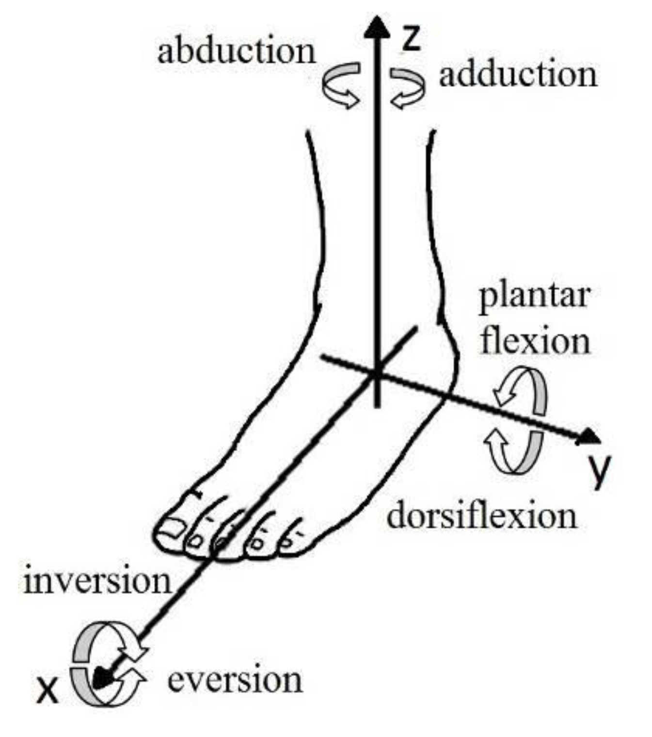
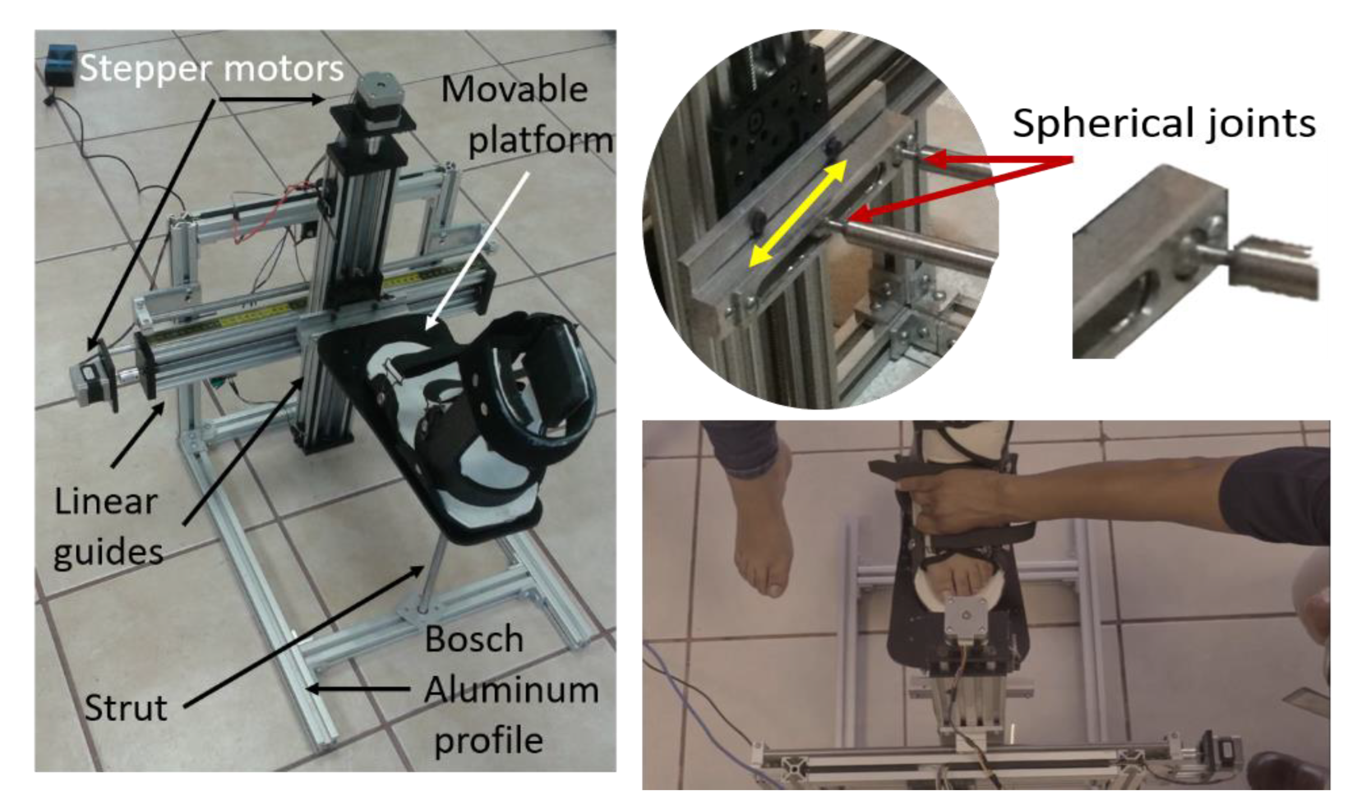
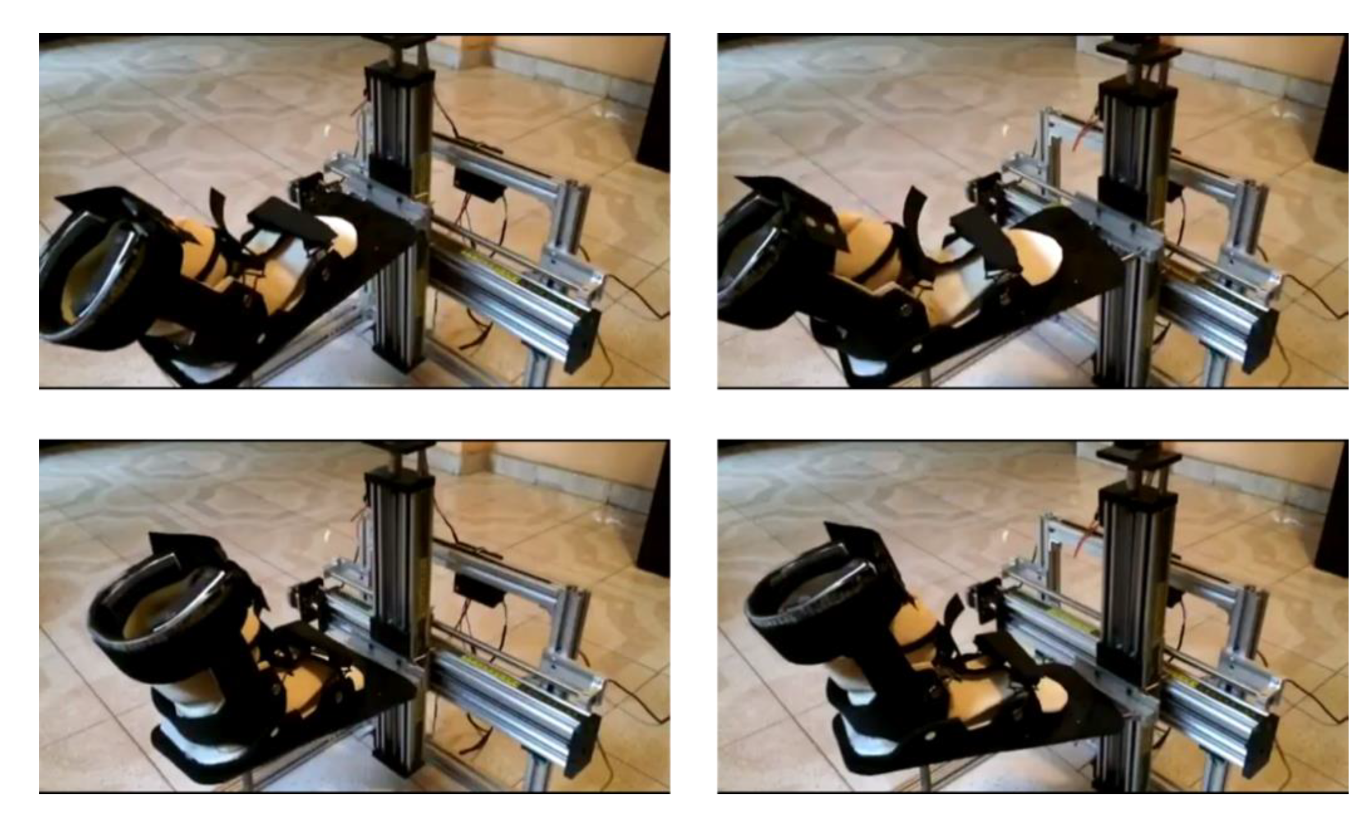
2.1. Ankle Rehabilitation Machine

For the design of the ankle rehabilitation machine, the movements that are present in the ankle and shown in Figure 1 were considered. The three movements that can be performed in the ankle are: (1) dorsiflexion/plantarflexion, (2) inversion/eversion and (3) abduction/adduction. In Table 2, the maximum intervals for each movement are shown [29].
Torque arising from passive ankle stiffness in post-stroke patients has also been reported [30], as shown in Figure 2. For a dorsiflexion movement, torque is considered positive, while for a plantarflexion movement is considered a negative torque.
The ankle rehabilitation machine proposed in [31] has two degrees of freedom (DOF) and is based on the movements of an X-Y table, using linear guides with an ACME screw. A new version of this rehabilitator is shown in Figure 3. In its design, a commercial modular profile was used for the structure and there are only six customized pieces for the rehabilitator assembly, all the other parts are standard components. Spherical joints, see Figure 3, were used to support the movable platform and connect with the mobile base of the Y linear guide (X-Y table). The actuators are Nema 17 stepper motors.
The ankle rehabilitator can provide the passive movements of dorsiflexion (DF)-plantarflexion (PF), abduction (AB) and adduction (AD), as well as a combination of these movements to obtain a more complex movement, such as performing a circle with the tip of the big toe in an imaginary plane (table X-Y).

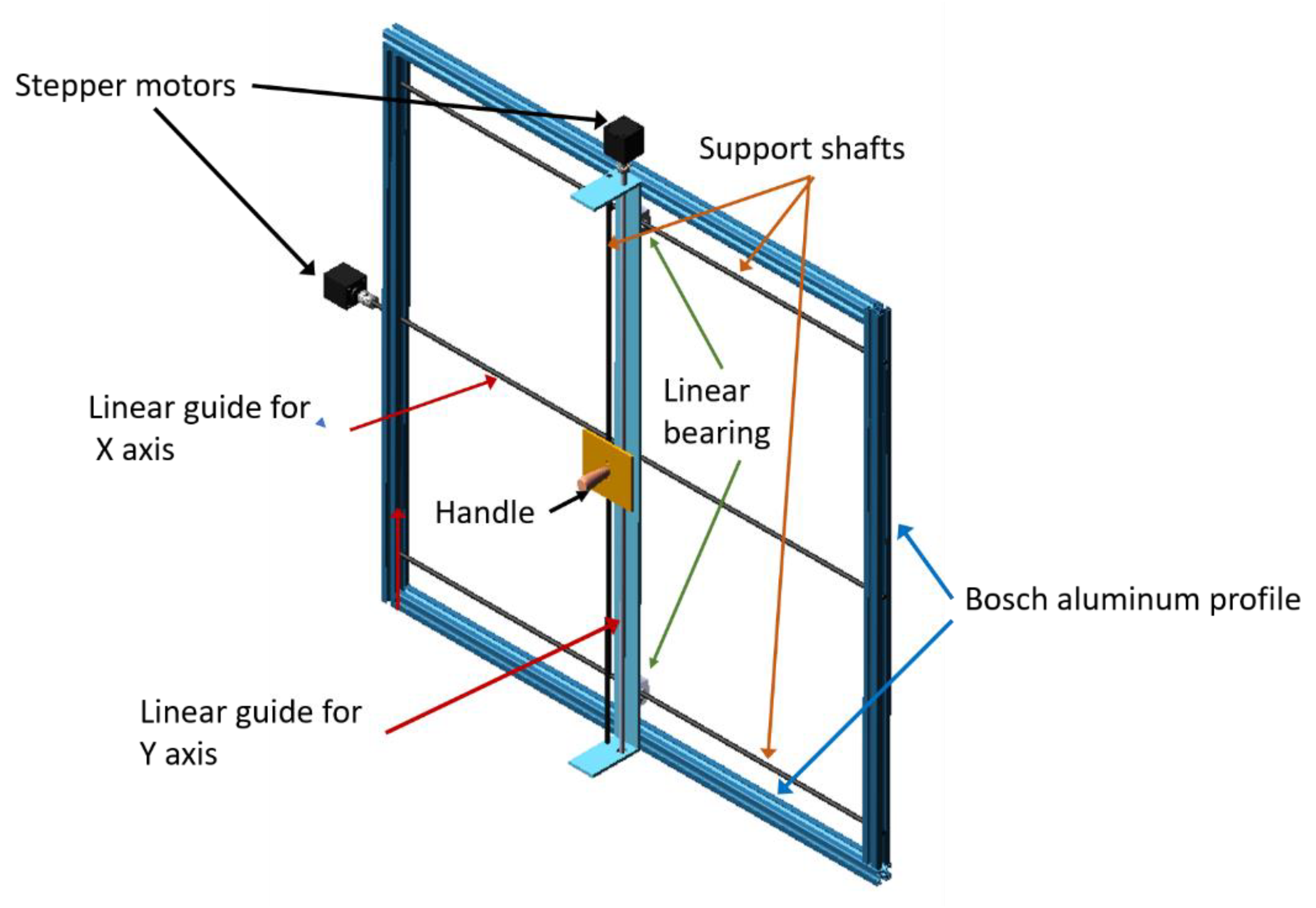
2.2. Shoulder Rehabilitation Machine

The shoulder joint is one of the most mobile in the human body. It has three DOF and is the most unstable joint in the body due to the amount of motion it allows. In the sagittal plane and around a transverse axis, it performs the movement of flexion (SF)—extension (SE). In the frontal plane and around an anteroposterior axis, it produces the abduction (SAB)—adduction (SAD) movement. In the transverse plane and around a vertical axis, it performs internal rotation (SIR)—external rotation (SER) movements [32], see Figure 4. Table 3 shows the maximum values that can be performed for each movement.
In Figure 5, the virtual prototype of the shoulder rehabilitation machine is shown. Similar to the ankle rehabilitation machine, Figure 3, it uses standard components and a Bosch modular profile. In this case, only the supports for the motors and some connection plates between the linear guides are the custom components. Therefore, this rehabilitator is also low cost, especially compared to more rigid-structure robotic systems.
The shoulder rehabilitation machine provides the passive movements of SF—SE, SAB—SAD and also the flexion (EF)—extension (EE) movements of the elbow. Furthermore, the machine can perform complex rehabilitation movements by moving the two axes and forming a figure in the imaginary plane of the X-Y table, such as the circle that represents the circumduction movement, see Figure 4.

2.3. Computer Numerical Control

Numerical control is a system for automating machines that are operated through programmed commands. Currently, this type of control is being extended to other applications where XYZ displacement movements are applied.
In addition, the use of CNC has advantages, such as [33]:
  • Automation of machine movements.
  • Flexible automation: it is based on a program that can be easily changed.
  • Possibility of leaving the machine working unattended.
  • Increase productivity.
  • The influence of the “operator skill” in handling the machine is reduced, programming machining of complex curves.
  • Improvement of precision and speed in movements.
The basic elements of numerical control are:
(a) The program, which contains all the information about the actions to be executed.
(b) The numerical control, which interprets these instructions, converts them into the corresponding signals for the drives of the machine and checks the results.
(c) The machine, which executes the foreseen operations.
Table 4 shows some codes to program in CNC. In the case of programming movements in rehabilitation systems, the codes G00, G01, G02 and G03 will mainly be used. In addition to these codes, miscellaneous functions and some letters that have a specific function within CNC programming are also used. The functions that were used in the programs presented in the results section were included in this table.
To carry out the programming based on coordinates in the respective movement axes, it is necessary to have a reference to have dimensions that make sense. Therefore, the definition of a coordinate system concerning the machine or the workpiece is important. In rehabilitation systems, this reference point is known as the Workpiece Zero Point; see Figure 6.
The hardware and software required for the implementation of CNC, to automate a machine, are shown in Figure 7. It is an Arduino expansion card or module known as CNC shield for the control of a CNC machine. The firmware for the control of CNC machines is loaded on the Arduino board; this firmware was developed by the Norwegian Simen Svale Skogsrud, who is known as the father of GRBL [34]. The GRBL firmware is in charge of translating the G code commands into control signals for the stepper motors.
The drivers for controlling the stepper motors are inserted in the CNC shield card.
It supports 4 A4988 or DRV8825 power drivers (4 stepper motors) and has all the necessary connections to connect limit switches, relay outputs and various sensors. It is fully compatible with GRBL control firmware and can be used with any Arduino model, although it is recommended to use an Arduino UNO model. The CNC Shield Driver must be configured for the type of stepper motor to be used.
The steps for transferring the GRBL firmware to the Arduino UNO are described below. The procedure is also shown in Figure 8.
  • Connect the Arduino UNO to the personal computer.
  • Run XLoader.exe.
  • In XLoader:
    • Select the HEX file that contains the GRBL.
    • Select the correct Arduino board.
    • Select the COM port connected to the Arduino.
    • Select the appropriate baud rate.
    • Select Upload to send the HEX file to Arduino.
4.
The indicator LEDs on the Arduino will start to blink and when finished XLoader will have been loaded on the Arduino UNO. Close the XLoader Window.
Various Open-Source programs can be used to load rehabilitation programs into the CNC (Universal Gcode Sender, GRBLcontroller, Goko, etc.). In this case, the Universal GcodeSender will be used; see Figure 9. Universal Gcode Sender is a Java-based, GRBL-compatible cross-platform G-code sender that can be used on most Windows, MacOSX, or Linux computers. This program is applied to run a GRBL controlled CNC machine with G-code commands; furthermore, it has a manual control mode to drive the stepper motors.
The Universal Gcode Sender is used to configure the GRBL (it must be connected to the Arduino UNO), in the command window enter $$. The parameters to configure will be displayed; to modify any, write $x = value. In this part, the motors and the linear displacement system (screw) are configured.

2.4. Hardware Configuration

Figure 10 shows the current and reference voltage relationship of the Nema 17 motor, and as suggested by the controller’s technical data sheets, it is suggested to adjust to 70% of the nominal motor current to calculate the Vref. For the stepping motors used, the Drivers were configured as shown in Table 5. Figure 11 shows how to adjust the Vref in the A4988 driver.
Once the rehabilitation machine has been configured and instrumented to program a routine, in the ankle or shoulder rehabilitator, the procedure shown in Figure 12 is followed. It begins with defining the type of rehabilitation movement for the patient, which will be provided or indicated by the rehabilitation specialist; subsequently, their respective G code is developed (manually or with the use of programs) and transferred through the Universal Gcode Sender through the Arduino-CNC-Shield array to the rehabilitation machine. It is recommended to test the CNC program first without the patient. Once the movement has been validated, the patient can start their rehabilitation routine.

2.5. Robust GPI Control

The Generalized Proportional Integral (GPI) controller is a technique for the design of controllers that can reject different types of polynomial disturbances, such as: constant perturbations, ramps, quadratic perturbations, etc. [35]. GPI control was introduced, within the context of predictive control of differentially flat systems [36].
The GPI controller avoids the explicit use of state observers by resorting to structural reconstructions of the state on the basis of iterated integrations of input-output. For dynamical systems, initial conditions and unknown perturbations are ignored by adding a suitable linear combination of iterated integrals of the output tracking error [35]. We propose an output feedback controller of the GPI type for a reference trajectory tracking task, which is based on position measurements of the controlled masses of the linear guides.
The ankle and shoulder rehabilitation machines consist of two linear guides, which provide the movements in the directions of the axes X (horizontal) and Y (vertical), Figure 13. For X axis motion, the mass m1 is considered, which corresponds to the sum of the movable platform mass and the mass of the whole linear guide system for the Y axis. For the Y axis, the mass m2 is considered due only to the carriage. Fx and Fy are the control forces for the motion of X and Y axes, respectively. Forces Px and Py are unknown disturbances (friction, viscous damping, unmodeled dynamics); in these simulations the linear torque functions that represent the stiffness in the joints are considered, as shown in Figure 2. The effect of gravity on the linear guides (x,y) is neglected, because in any position, even with the weight of the patient’s foot, it is not capable of overcoming the system, so it remains in equilibrium.
The mathematical model governing the dynamic for the rehabilitation machines can be obtained by applying Newton’s second law, which is given by:
m 1 x ¨ = F x P x m 2 y ¨ = F y P y
To design a controller for position reference tracking, consider Equation (1). Then, one can propose the following robust Generalized Proportional Integral (GPI) controller for asymptotic and robust tracking to the desired position trajectory, which employs only linear position measurements of the movable platform. For more details on GPI control, see [35,36,37].
Consider the perturbed system as
x ¨ = U x + ξ
with
U x = F x m 1 , ξ = P x m 1 x ˙ = 0 t U x ( σ ) d σ + x ˙ ( 0 ) x ˙ = x ˙ ^ + x ˙ ( 0 ) x ˙ ^ = 0 t U x ( σ ) d σ
where x ˙ ^ is the integral reconstruction of the linear guide velocity in the x axis. Considering that the disturbance ξ (passive ankle stiffness) can be approximated as a third-order polynomial, such as:
ξ = a t 3 + b t 2 + c t + d
The control strategy for the rejection of unknown disturbances and dynamic changes for the ankle–joint rehabilitation robot is given by the following robust GPI controller,
U x = x ¨ 1 d k 5 ( x ˙ 1 z ˙ 1 d ) k 4 ( x 1 x 1 d ) k 3 0 t ( x 1 x 1 d )   d τ k 2 0 t 0 τ ( x 1 x 1 d )   d λ d τ k 1 0 t 0 τ 0 λ ( x 1 x 1 d ) d σ d λ d τ k 0 0 t 0 τ 0 λ 0 σ ( x 1 x 1 d )   d ρ d σ d λ d τ ,
By substituting the robust GPI controller (Equation (4)) in Equation (2), the following closed-loop dynamic equation for the trajectory tracking error ( e = x 1 x 1 d , e ˙ = x ˙ 1 x ˙ 1 d , e ¨ = x ¨ 1 x ¨ 1 d , ) is obtained.
e V I + k 5 e V + k 4 e I V + k 3 e + k 2 e ¨ + k 1 e ˙ + k 0 e = 0 ,
Applying the Laplace transform to Equation (5) with initial conditions equal to zero, the characteristic equation of the closed-loop system is obtained:
s 6 + k 5 s 5 + k 4 s 4 + k 3 s 3 + k 2 s 2 + k 1 s + k 0 = 0 ,
The controller gains (ki, i = 0, 1,…,5) are determined by equating a Hurwitz polynomial (Equation (7)) so that the error dynamics are asymptotically stable. For this case, were selected ζ = 2 , ω = 10 .
( s + 2 ζ ω s + ω 2 ) 3 = 0 ,
As a result, the GPI controller can be written in a classical compensation network form, where the expression was combined with time and frequency domain quantities, as is customary in many areas of modern control.
U x = U d ( k 4 s 4 + k 3 s 3 + k 2 s 2 + k 1 s + k 0 s 3 ( s + k 5 ) ) ( x 1 x 1 d ) ,

3. Results

3.1. Rehabilitation Exercise Routine

For ankle (or shoulder) rehabilitation movements, a relationship between the displacement of the linear guide with respect to the desired angle (DF, PF, AB, AD) must be established. For a positive displacement of the X axis (+x) we have an angle (φ) of AD and for a negative displacement in the X axis (−x) we have an angle (φ) of AB; relative to a right foot. On the other hand, for a positive displacement of the Y axis (+y) there is an angle (θ) of DF and for a negative displacement on the Y axis (−y) there is an angle (θ) of PF, see Figure 14. Table 6 shows the numerical relationship between the displacement of the linear guides and the angle obtained for each ankle rehabilitation movement.
For the development of the programs, the rehabilitation routines were elaborated in the CNC syntax considering the basic movements of DF, PF, AB and AD, as well as combined movements. These were classified into three levels: beginner, intermediate and advanced (Figure 15); the difference is the degree of opening, speed, cycles or repetitions, time and sustain of the foot’s trajectory. These programs must be indicated and under the supervision and evaluation of the physiotherapist depending on the patient’s recovery.
Figure 16 shows the G-Code for two routines for a beginner-level dorsiflexion movement. In G code_1, the units are defined in mm (G21) starting at the workpiece zero point (G00 X0 Y0), then it goes up 20 mm (y+) with a feed rate of 200 mm/min (G01 Y20 F200), then returns to the origin with the same speed (G01 Y0 F200), repeating the cycle 4 more times. Finally, it stops the program and returns to the beginning (M30). In G code_2, only the amplitude of movement is changed to 50 mm with a speed of 500 mm/min (G01 Y50 F500) and it also performs the 5 cycles.
Similarly, Figure 17 shows the G-Code of two routines for a dorsiflexion movement at the intermediate level. In G code_1 the units are defined in mm (G21) and it starts at the workpiece zero point (G00 X0 Y0), then goes up 70 mm (y+) with a feed rate of 800 mm/min (G01 Y70 F800), then returns to the origin with the same speed (G01 Y0 F800), repeating the cycle 4 more times. Finally, the program stops and returns to the beginning of the program (M30). In G code_2, only the movement amplitude is changed to 100 mm with a speed of 1000 mm/min (G01 Y100 F1000), and it also performs the 5 cycles.
For an advanced-level routine, see Figure 18; a dorsiflexion amplitude of 120 mm with a speed of 1500 mm/min is considered in G code 1, and in G code_2 a dorsiflexion amplitude of 150 mm with a speed of 2000 mm/min; in this case, 5 cycles are also considered.
The advantage of using CNC for programming movements in the X and Y axis is that combined and complex movements can be carried out more easily compared to a classic or modern control system. In Figure 19, the movement of a circle in the imaginary X-Y plane is shown. In G code 1, for a beginner level, it has a radius of 20 mm and a speed of 500 mm/min, while for an Advanced level, it has an amplitude of 150 mm and a speed of 2000 mm/min. In these examples presented, only 5 cycles were considered, but they may vary depending on the level of rehabilitation or the indications of the Physiotherapy specialist.
Four images of the physical prototype of the ankle rehabilitation machine are shown in Figure 20 for a beginner-level movement that performs a square in the imaginary X-Y plane. They were captured in the 4 corners of the square. To test the functionality and advantages of CNC, programs were made for saw, triangular, and arc movements, among others, which perform combined movements. Furthermore, programs that trace the letters of the alphabet were carried out (see Table 7), which are some of the movements that specialists ask patients to carry out in their rehabilitation process. All routines were tested only with the rehabilitation machine, without the user. Some routines were tested with a user without injuries (a healthy person) on the ankle and shoulder rehabilitation machines.
Some programs were also used for the shoulder rehabilitator, modifying only the amplitudes of movement. In Figure 21, the shoulder rehabilitator is shown in different positions. In this case, it is recommended to use a glove to support the patient’s arm on the handle, and it can be used for passive rehabilitation of stroke patients. In addition, it is recommended to use splints when you want the arm to be fully extended and thus perform the flexion, extension, abduction or adduction movements; see Figure 21 and Figure 22.

3.2. Desired Reference Trajectory

The machines for rehabilitation must guarantee safe rehabilitation movements. Given that, the movements must be smooth and continuous. The desired reference trajectories are given by the following Bezier polynomial.
x d ( t ) = { 0 x 10 x f       0 t < t i t i t < t f t > t f
x 10 ( t ) = x i + ( x f x i ) ( a 0 a 1 μ + a 2 μ 2 a 3 μ 3 + a 4 μ 4 a 5 μ 5 ) μ 5 μ = t t i t f t i
where xi = xd (ti) is the initial desired position and xf = xd (tf) is the final desired position. The parameters of the Bezier polynomial were selected as: a0 = 252, a1 = 1050, a2 = 1800, a3 = 1575, a4 = 700 and a5 = 126.

3.3. Robust Controller

The results presented in Figure 23, Figure 24, Figure 25, Figure 26 and Figure 27 were obtained using the virtual prototype in the MCS Adams environment in co-simulation with Matlab-Simulink. The GPI controller uses the same gains in all simulations and the same Bezier polynomial, for values of xf = 0.05 and 0.1 m. Figure 23 shows the simulation results for an abduction movement of 9.45°, x = 0.05 m, without considering disturbances. Only the inertia of the components that are going to move is considered. It is observed that the robust GPI controller follows the path that shows smooth behavior. At the x position, the actual and desired trajectories are shown. Similarly, in Figure 25, the response for the same abduction movement (φ = 9.45°, x = 0.05 m) is shown but with disturbance; see Figure 24. Again, the controller follows the trajectory smoothly, and the error is so minimal that the difference between the actual and desired response is not noticeable, both responses showing up in the response of x.
Figure 26 shows the robust GPI controller response for a dorsiflexion movement of 18.4°, 0.1 m. Similarly, the controller follows the desired trajectory compensating for the disturbance (Figure 2) considered to be stiffness in the ankle joint.
Figure 27 shows the robust GPI controller response for a combined dorsiflexion (y = 0.05 m) and abduction (x = 0.05 m) movement. Similarly, the controller follows the desired trajectory compensating for the disturbance (Figure 2) in both movements.

4. Discussion

The use of automated CNC machines has shown that they can be programmed by users without any specialized knowledge. In addition, these rehabilitation machines, as shown in the routine codes presented in this work, require the use of only a few G Code commands, as well as miscellaneous functions. Specialists or users themselves can program and customize their rehabilitation routines. The use of open-source software also contributes to the reduction of the cost of the machine. On the other hand, a sufficient number of programs can be carried out to cover rehabilitation demands, depending on the injury and the specialist’s indications.
In a therapy session, changing the routine to the patient is also easy and takes minimal time (just upload the routine file to the software—Universal G Code Sender). Another advantage of using the Universal G Code Sender is that, in manual mode, the specialist can identify the maximum value of movement allowed by the user without causing pain, by manually increasing the angle at the ankle or shoulder, to later load the program with the appropriate routine for rehabilitation.

5. Conclusions

A large number of ankle and shoulder rehabilitation devices have been proposed in the literature. However, most of the proposed ankle rehabilitation machines use linear actuators, which turn out to be expensive, compared to the stepping motors used in these rehabilitation machines presented in this paper. Furthermore, shoulder rehabilitation systems generally have a rigid and robust structure in which, due to inertia, a number of components and links require actuators that provide a large torque, which also raises the cost of these rehabilitation devices.
In this paper, two low-cost rehabilitation machines are proposed: ankle and shoulder. These use a Bosch modular aluminum profile, few standard components, ACME screw linear guide system and stepper motors, resulting in a low-cost structure. However, the greatest advantage lies in the use of the CNC, which gives it greater functionality, reducing the complexity of routine programming by the specialist or the user. With the CNC it is possible to perform rehabilitation routines with combined and complex movements (Table 7), and it is easy to develop the rehabilitation movement code.
Finally, from the state of the art and the work carried out, the following guidelines or trends for future work are given:
Develop serious games (video games) so that the patient can focus on their rehabilitation process and find it entertaining or fun [38].
Monitor myoelectric signals with surface myoelectric sensors to reduce the improvement time of the affected muscles by proposing rehabilitation routines that help in their process, as well as to determine joint stiffness.
Combine with other means or mechanisms (water, electrostimulation, etc.) [17] to increase the speed of improvement of the joint or damaged muscles.
Implement resistive rehabilitation using force sensors, and combine this stage with serious games to motivate the patient [38].
Characterization of stiffness in the ankle and shoulder joints using a rehabilitation machine combined with some parameter identification method.
Development of physical prototypes for low-cost rehabilitation that is within the reach of people who require rehabilitation.

6. Patents

There is a patent for the ankle rehabilitator (No. 353502), which was granted on 12/14/2017 by the IMPI (Mexican Institute of Industrial Property).

Author Contributions

Conceptualization, A.B.O., F.A.G.B. and J.A.S.C.; methodology, A.M.S., C.H.G.V. and M.J.P.G.; software, A.B.O. and A.M.S.; validation, J.A.S.C. and C.H.G.V.; formal analysis, M.A.G.V.; investigation, J.A.S.C.; resources, C.H.G.V.; data curation, F.A.G.B.; writing—original draft preparation, M.J.P.G.; writing—review and editing, M.A.G.V.; visualization, A.M.S.; supervision, A.B.O.; project administration, F.A.G.B.; funding acquisition, A.B.O. and M.A.G.V. All authors have read and agreed to the published version of the manuscript.

Funding

This research received no external funding.

Institutional Review Board Statement

Not applicable.

Informed Consent Statement

Not applicable.

Data Availability Statement

Not applicable.

Conflicts of Interest

The authors declare no conflict of interest.

References

  1. Alvarez-Perez, M.G.; Garcia-Murillo, M.A.; Cervantes-Sánchez, J. Robot-assisted ankle rehabilitation: A review. Disabil. Rehabil. Assist. Technol. 2019, 15, 394–408. [Google Scholar] [CrossRef] [PubMed]
  2. Chee Chin, L.C.; Basah, S.N.; Affandi, M.; Shah, M.N.; Yaacob, S.; Ewe Juan, Y.; Din, M.Y. Home-based Ankle Rehabilitation System: Literature Review and Evaluation. J. Teknol. 2017, 79, 6. [Google Scholar] [CrossRef] [Green Version]
  3. Demofonti, A.; Carpino, G.; Zollo, L.; Johnson, M.J. Affordable Robotics for Upper Limb Stroke Rehabilitation in Developing Countries: A Systematic Review. IEEE Trans. Med Robot. Bionics 2021, 3, 11–20. [Google Scholar] [CrossRef]
  4. Qassim, H.M.; Hasan, W.Z.W. A Review on Upper Limb Rehabilitation Robots. Appl. Sci. 2020, 10, 6976. [Google Scholar] [CrossRef]
  5. Alcocer, W.; Vela, L.; Blanco, A.; Gonzalez, J.; Oliver, M. Major Trends in the Development of Ankle Rehabilitation Devices. Dyna 2012, 79, 45–55. [Google Scholar]
  6. Hogan, N.; Krebs, H.I.; Charnnarong, J.; Srikrishna, P.; Sharon, A. MIT-MANUS: A workstation for manual therapy and training. In Proceedings of the IEEE International Workshop on Robot and Human Communication, Tokyo, Japan, 1–3 September 1992; pp. 161–165. [Google Scholar]
  7. Dehez, B.; Sapin, J. ShouldeRO, An alignment-free two-DOF rehabilitation robot for the shoulder complex. In Proceedings of the 2011 IEEE International Conference on Rehabilitation Robotics, Zurich, Switzerland, 29 June–1 July 2011; pp. 1–8. [Google Scholar]
  8. Ball, S.J.; Brown, I.E.; Scott, S.H. MEDARM: A rehabilitation robot with 5DOF at the shoulder complex. In Proceedings of the 2007 IEEE/ASME International Conference on Advanced Intelligent Mechatronics, Zurich, Switzerland, 4–7 September 2007; pp. 1–6. [Google Scholar] [CrossRef]
  9. Chen, S.-H.; Lien, W.-M.; Wang, W.-W.; Lee, G.-D.; Hsu, L.-C.; Lee, K.-W.; Lin, S.-Y.; Lin, C.-H.; Fu, L.-C.; Lai, J.-S.; et al. Assistive Control System for Upper Limb Rehabilitation Robot. IEEE Trans. Neural Syst. Rehabil. Eng. 2016, 24, 1199–1209. [Google Scholar] [CrossRef] [PubMed]
  10. Zeiaee, A.; Soltani-Zarrin, R.; Langari, R.; Tafreshi, R. Design and kinematic analysis of a novel upper limb exoskeleton for rehabilitation of stroke patients. In Proceedings of the International Conference on Rehabilitation Robotics (ICORR), London, UK, 17–20 July 2017; pp. 759–764. [Google Scholar] [CrossRef]
  11. Niyetkaliyev, A.S.; Hussain, S.; Ghayesh, M.H.; Alici, G. Review on Design and Control Aspects of Robotic Shoulder Rehabilitation Orthoses. IEEE Trans. Hum. Mach. Syst. 2017, 47, 1134–1145. [Google Scholar] [CrossRef] [Green Version]
  12. Cornejo, J.; Huamanchahua, D.; Huaman-Vizconde, S.; Terrazas-Rodas, D.; Sierra-Huertas, J.; Janampa-Espinoza, A.; Gonzales, J.; Cardona, M. Mechatronic Exoskeleton Systems for Supporting the Biomechanics of Shoulder-Elbow-Wrist: An Innovative Review. In Proceedings of the 2021 IEEE International IOT, Electronics and Mechatronics Conference (IEMTRONICS), Toronto, ON, Canada, 21–24 April 2021; pp. 1–9. [Google Scholar] [CrossRef]
  13. Gull, M.A.; Bai, S.; Bak, T. A Review on Design of Upper Limb Exoskeletons. Robotics 2020, 9, 16. [Google Scholar] [CrossRef]
  14. Islam, R.; Spiewak, C.; Rahman, M.H.; Fareh, R. A Brief Review on Robotic Exoskeletons for Upper Extremity Rehabilitation to Find the Gap between Research Porotype and Commercial Type. Adv. Robot. Autom. 2017, 6, 177. [Google Scholar] [CrossRef]
  15. Hood-Daniel, P.; Floyd-Kelly, J. Build Your Own CNC Machine; Apress: Pune, India, 2009. [Google Scholar]
  16. Suk-hwan, S.; Seong-kyoon, K.; Dae-hyuk, C.; Stroud, I. Theory and Design of CNC Systems; Springer: Berlin/Heidelberg, Germany, 2008. [Google Scholar]
  17. Guzmán-Valdivia, C.H.; Madrigal-López, O.; Désiga-Orenday, O.; Talavera-Otero, J.; Brizuela-Mendoza, J.A.; Chávez-Olivares, C.A.; Cruz-Domínguez, O.; Blanco-Ortega, A.; Berumen-Torres, J.A.; Gómez-Becerra, F.A. Design, Development and Control of a Therapeutic Robot Incorporating Aquatic Therapy for Ankle Rehabilitation. Machines 2021, 9, 254. [Google Scholar] [CrossRef]
  18. Zeng, D.; Wu, H.; Zhao, X.; Lu, W.; Luo, X. A New Type of Ankle-Foot Rehabilitation Robot Based on Muscle Motor Characteristics. IEEE Access 2020, 8, 215915–215927. [Google Scholar] [CrossRef]
  19. Li, J.; Fan, W.; Dong, M.; Rong, X. Research on control strategies for ankle rehabilitation using parallel mechanism. Cogn. Comput. Syst. 2020, 2, 105–111. [Google Scholar] [CrossRef]
  20. Abu-Dakka, F.J.; Valera, A.; Escalera, J.A.; Abderrahim, M.; Page, A.; Mata, V. Passive Exercise Adaptation for Ankle Rehabilitation Based on Learning Control Framework. Sensors 2020, 20, 6215. [Google Scholar] [CrossRef] [PubMed]
  21. Vallés, M.; Díaz-Rodríguez, M.; Valera, A.; Mata, V.; Page, A. Mechatronic Development and Dynamic Control of a 3-DOF Parallel Manipulator. Mech. Based Des. Struct. Mach. 2012, 40, 434–452. [Google Scholar] [CrossRef] [Green Version]
  22. Minh Duc, D.; Thuy Tram, L.T.; Dang Phuoc, P.; Xuan Tuy, T. Study on Ankle Rehabilitation Device Using Linear Motor. In Proceedings of the 2019 International Conference on System Science and Engineering (ICSSE), Dong Hoi, Vietnam, 20–21 July 2019; pp. 573–576. [Google Scholar] [CrossRef]
  23. Wang, C.; Wang, L.; Wang, T.; Li, H.; Du, W.; Meng, F.; Zhang, W. Research on an Ankle Joint Auxiliary Rehabilitation Robot with a Rigid-Flexible Hybrid Drive Based on a 2-S′′PS′′ Mechanism. Appl. Bionics Biomech. 2019, 2019, 7071064. [Google Scholar] [CrossRef] [Green Version]
  24. Zhang, M.; Cao, J.; Xie, S.Q.; Zhu, G.; Zeng, X.; Huang, X.; Xu, Q. A Preliminary Study on Robot-Assisted Ankle Rehabilitation for the Treatment of Drop Foot. J. Intell. Robot. Syst. 2017, 91, 207–215. [Google Scholar] [CrossRef]
  25. Alcocer-Rosado, W.; Vela-Valdés, L.; Blanco-Ortega, A.; Ruiz-Ascencio, J.; García-Beltrán, C.D. Passive Rehabilitation Exercises with an Ankle Rehabilitation Prototype Based in a Robot Parallel Structure. IEEE Lat. Am. Trans. 2017, 15, 48–56. [Google Scholar] [CrossRef]
  26. Rosado, W.M.A.; Ortega, A.B.; Valdes, L.G.V.; Ascencio, J.R.; Beltrán, C. Active Rehabilitation Exercises With a Parallel Structure Ankle Rehabilitation Prototype. IEEE Lat. Am. Trans. 2017, 15, 786–794. [Google Scholar] [CrossRef]
  27. Wang, C.; Wang, L.; Qin, J.; Wu, Z.; Duan, L.; Li, Z.; Cao, M.; Li, W.; Lu, Z.; Li, M.; et al. Development of an ankle rehabilitation robot for ankle training. In Proceedings of the Information and Automation, Lijiang, China, 8–10 August 2015; pp. 94–99. [Google Scholar] [CrossRef]
  28. Jamwal, P.K.; Xie, S.Q.; Hussain, S.; Parsons, J.G. An Adaptive Wearable Parallel Robot for the Treatment of Ankle Injuries. IEEE/ASME Trans. Mechatron. 2012, 19, 64–75. [Google Scholar] [CrossRef]
  29. Tsoi, Y.H.; Xie, S.Q.; Graham, A.E. Design, Modeling and Control of an Ankle Rehabilitation Robot. In Design and Control of Intelligent Robotic Systems; Liu, D., Wang, L., Tan, K.C., Eds.; Studies in Computational Intelligence; Springer: Berlin/Heidelberg, Germany, 2009; Volume 177. [Google Scholar] [CrossRef]
  30. Roy, A.; Krebs, H.I.; Bever, C.T.; Forrester, L.W.; Macko, R.F.; Hogan, N. Measurement of passive ankle stiffness in subjects with chronic hemiparesis using a novel ankle robot. J. Neurophysiol. 2011, 105, 2132–2149. [Google Scholar] [CrossRef] [Green Version]
  31. Blanco-Ortega, A.; Gómez-Becerra, F.A.; Vela-Valdés, L.G.; Delgado-Arcega, R.O. A Generalized Proportional Integral Controller for an Ankle Rehabilitation Machine Based on an XY Table. In Proceedings of the 2013 International Conference on Mechatronics, Electronics and Automotive Engineering, Morelos, Mexico, 19–22 November 2013; pp. 152–157. [Google Scholar] [CrossRef]
  32. Angulo Carrere, M.T.; Álvarez Méndez, A.; Fuentes Peñaranda, Y. Biomecánica clínica. Biomecánica de la Extremidad Superior. Exploración del Hombro. Reduca Enfermería Fisioter. Podol. 2011, 3, 104–123. [Google Scholar]
  33. Graham, S. CNC Machining Technology. Volume I. Design, Development and ClM Strategies; Springer-Verlag: Berlin/Heidelberg, Germany, 1993. [Google Scholar]
  34. GRBL CNC Controller. Popular Repositories. Available online: https://github.com/grbl/grbl (accessed on 28 April 2022).
  35. Sira-Ramírez, H.; Beltran-Carbajal, F.; Blanco-Ortega, A. A generalized proportional integral output feedback controller for the robust perturbation rejection in a mechanical system. e-STA 2008, 5, 24–32. [Google Scholar]
  36. Fliess, M.; Márquez, R.; Delaleau, E.; Sira-Ramírez, H. Correcteurs proportionnels-integraux Généralisés. ESAIM Control. Optim. Calc. Var. 2002, 7, 23–41. [Google Scholar] [CrossRef] [Green Version]
  37. Blanco-Ortega, A.; Vázquez-Sánchez, L.; Adam-Medina, M.; Colín-Ocampo, J.; Abúndez-Pliego, A.; Cortés-García, C.; García-Beltrán, C.D. A Robust Controller for Upper Limb Rehabilitation Exoskeleton. Appl. Sci. 2022, 12, 1178. [Google Scholar] [CrossRef]
  38. Magadán-Salazar, A.; Blanco-Ortega, A.; Gama-Velasco, A.K.; Abúndez-Pliego, A. Mechatronic Integral Ankle Rehabilitation System: Ankle Rehabilitation Robot, Serious Game, and Facial Expression Recognition System. In Advanced Topics on Computer Vision, Control and Robotics in Mechatronics; Vergara Villegas, O., Nandayapa, M., Soto, I., Eds.; Springer International Publishing: Cham, Switzerland, 2018; pp. 291–320. [Google Scholar]
Figure 1. Ankle joint movements.
Machines 10 01055 g001
Figure 2. Passive ankle stiffness for a dorsiflexion-plantarflexion movement in stroke survivors.
Machines 10 01055 g002
Figure 3. Ankle rehabilitation machine.
Machines 10 01055 g003
Figure 4. Shoulder joint movements.
Machines 10 01055 g004
Figure 5. Shoulder rehabilitation machine.
Machines 10 01055 g005
Figure 6. Workpiece zero point in rehabilitation machines: (a) Ankle and (b) Shoulder.
Machines 10 01055 g006
Figure 7. Arduino—CNC shield control—Stepper motor with A4988 driver.
Machines 10 01055 g007
Figure 8. Procedure for transferring the GRBL firmware in Arduino UNO. (a) connect Arduino UNO, (b) Configure XLoader and (c) Load GRBL firmware on Arduino.
Machines 10 01055 g008
Figure 9. Universal Gcode Sender.
Machines 10 01055 g009
Figure 10. Vref setting values with Rs = 0.2 ohms with respect to motor current.
Machines 10 01055 g010
Figure 11. Vref adjustment through potentiometer.
Machines 10 01055 g011
Figure 12. Procedure to implement a routine in the rehabilitation machine.
Machines 10 01055 g012
Figure 13. Free body diagram of the ankle rehabilitation machine.
Machines 10 01055 g013
Figure 14. Relation between linear displacement vs ankle rehabilitation angle.
Machines 10 01055 g014
Figure 15. Rehabilitation levels on ankle rehabilitation machine.
Machines 10 01055 g015
Figure 16. Beginner level for dorsiflexion rehabilitation.
Machines 10 01055 g016
Figure 17. Intermediate level for dorsiflexion rehabilitation.
Machines 10 01055 g017
Figure 18. Advanced level for dorsiflexion rehabilitation.
Machines 10 01055 g018
Figure 19. Circular trajectory for ankle rehabilitation movement.
Machines 10 01055 g019
Figure 20. Physical prototype of the ankle rehabilitation machine.
Machines 10 01055 g020
Figure 21. Physical prototype of the shoulder rehabilitation machine.
Machines 10 01055 g021
Figure 22. Elbow splint immobilizer.
Machines 10 01055 g022
Figure 23. Response for an abduction movement φ = 9.45°, x = 0.05 m, without disturbance.
Machines 10 01055 g023
Figure 24. Perturbation for an abduction (blue line)-adduction (red line) movement.
Machines 10 01055 g024
Figure 25. Response for an abduction movement φ = 9.45°, x = 0.05 m, with disturbance.
Machines 10 01055 g025
Figure 26. Response for a dorsiflexion movement φ = 18.4°, x = 0.1 m, with disturbance.
Machines 10 01055 g026
Figure 27. Response for a combined movement of dorsiflexion and abduction, with disturbance.
Machines 10 01055 g027
Table 2. Ankle range of motion [29].
Type of MotionMax. Allowable Motion
Dorsiflexion20.3° a 29.8°
Plantarflexion37.6° a 45.8°
Inversion14.5° a 22.0°
Eversion10.0° a 17.0°
Abduction15.4° a 25.9°
Adduction22.0° a 36.0°
Table 3. Shoulder range of motion.
Type of MotionMax. Allowable
Flexion180°
Extension50°
Adduction48°
Abduction134°
Internal rotation34°
External rotation142°
Circumduction360°
Table 4. CNC Codes list.
CodeFunctionCodeFunction
G00Positioning at rapid travelG01Linear interpolation using a feed rate;
G02Circular interpolation clockwiseG03Circular interpolation, counterclockwise;
G17Select X-Y planeG18Select Z-X plane;
G19Select Z-Y planeG20Imperial units;
G21Metric unitsG27Reference return check;
M00Automatic stop (CNC program end)M02End of CNC program
M30End of tape (End of CNC program, with return to CNC program top)
RIt gives the radius of the arcs the machine makesNN gives the line number
PTo jump in time or a delayed time
X, Y, ZThese three values indicate the tools’ position in three dimensions—X and Y represent the horizontal and vertical dimensions, respectively, while Z represents the depthFTo indicate how quickly the machine feeds the piece
Table 5. Vref of the A4988 drivers.
Driver R s I m a x = 0.7   ( I n o m ) V r e f = I m a x   ( 8   X   R s )
Machines 10 01055 i0010.1 Ω1.176 amp. V r e f = 0.94   volts
Machines 10 01055 i0020.2 Ω1.176 amp. V r e f = 1.88   volts
Table 6. Relation between the displacement of the linear guide vs angle movement.
Dorsiflexion (DF)Plantarflexion (PF)Abduction (AB)Adduction (AD)
mmDegreesmmDegreesmmDegreesmmDegrees
102.2026−10−2.2026102.2026−10−2.2026
204.3987−20−4.3987204.3987−20−4.3987
306.5819−30−6.5819306.5819−30−6.5819
408.7462−40−8.7462408.7462−40−8.7462
5010.886−50−10.8865010.886−50−10.886
6012.995−60−12.9956012.995−60−12.995
7015.068−70−15.0687015.068−70−15.068
8017.103−80−17.1038017.103−80−17.103
9019.093−90−19.0939019.093−90−19.093
10021.038−100−21.03810021.038−100−21.038
11022.932−110−22.93211022.932−110−22.932
12024.775−120−24.77512024.775−120−24.775
13026.565−130−26.56513026.565−130−26.565
14028.301−140−28.301 −140−28.301
15029.982−150−29.982 −150−29.982
−160−31.608 −160−31.608
−170−33.179 −170−33.179
−180−34.695 −180−34.695
−190−36.158 −190−36.158
−200−37.569
−210−38.928
−220−40.236
Table 7. G code for rehabilitation movements.
LetterTrajectoryG Code
Machines 10 01055 i003Machines 10 01055 i004Machines 10 01055 i005
Machines 10 01055 i006Machines 10 01055 i007Machines 10 01055 i008
Machines 10 01055 i009Machines 10 01055 i010Machines 10 01055 i011
Publisher’s Note: MDPI stays neutral with regard to jurisdictional claims in published maps and institutional affiliations.

