Article

Mechanism Design and Performance Analysis of a Wearable Hand Rehabilitation Robot

1
Hebei Provincial Key Laboratory of Parallel Robot and Mechatronic System, Yanshan University, Qinhuangdao 066004, China
2
Academy for Engineering & Technology, Fudan University, Shanghai 200433, China
3
Contec Medical Systems Co., Ltd., Qinhuangdao 066004, China
4
Operating Room, Qinhuangdao Hospital of Traditional Chinese Medicine, Qinhuangdao 066004, China
*
Author to whom correspondence should be addressed.
Machines 2022, 10(12), 1211; https://doi.org/10.3390/machines10121211
Submission received: 8 November 2022 / Revised: 9 December 2022 / Accepted: 11 December 2022 / Published: 13 December 2022
(This article belongs to the Special Issue State-of-the-Art in Service and Rehabilitation Machines)

Abstract

:
Hand rehabilitation is critical to the recovery of post-stroke patients. However, designing a modular mechanism of the hand to improve the human-machine compatibility and precision of operation is still a challenge. This paper proposes a new type of hand exoskeleton rehabilitation robot with nine degrees of freedom. With the flexible rods, the passive range of motion for finger adduction/abduction is extended under the premise of independent flexion/extension of the metacarpophalangeal and proximal interphalangeal joint. Based on hand anatomy, the relationship between the offset of the metacarpophalangeal joint and the body height in the process of flexion and extension is discussed, and it is applied to the structure optimization and control system. The genetic algorithm is employed to achieve the size optimization, and the kinematics is analyzed. Finally, a prototype is built and preliminary experiments are carried out, including the range of motion and the grasping ability of the robot. The experimental results show that the robot can realize the patients’ hand rehabilitation function and has certain adaptability.

1. Introduction

Stroke is still the main cause of death. The global lifetime risk of stroke from 25 years onward has increased from 22.8% in 1990 to 24.9% in 2016 [1]. According to the World Health Organization (WHO), more than 15 million people worldwide suffer from stroke every year, and approximately 60% of stroke patients have lifelong hand dysfunction [2]. However, hands play almost the most important role in the activities of daily living (ADLs), which covers 54% of body motion function, so paying more attention to hand rehabilitation is an urgent demand [3]. With the development of the interdisciplinary medical-industrial, rehabilitation with the robot is gaining acceptance due to its unique advantages, such as assisting physicians with repetitive and tedious training exercises, providing vivid and interesting virtual scenes, etc. However, researchers currently focus more on the rehabilitation of large joints (shoulder, elbow, wrist, hip, knee, and ankle) and less on hand rehabilitation, which to a certain extent reduces the cure rate of hands [4]. Therefore, in-depth research and development of hand rehabilitation robots should be to carried out.
Researchers have achieved excellent results on hand rehabilitation robots, and each of them has its characteristics. Inspired by the detailed reviews [5], this paper analyzes typical hand rehabilitation robots based on their rigidity, and they can be divided into three types: rigid, hybrid, and soft. The rigid type devices usually consist of rigid materials and structures, such as linkages, gears, slide rails, etc. Amadeo [6] is an end-effector commercially available device with rehabilitation modalities, including passive, assisted, and active motions. The rigid exoskeleton developed by Orlando et al. [7] is used for the index and thumb, it adopts four-bar mechanisms to transmit power, and the motors are arranged on the side of the finger. The robot presented by Kawasaki et al. [8] consists of gears and linkages, and it has 18 degrees of freedom (DoF). It can drive all the joints of the hand but at the cost of a large number of motors and a complex structure. For easy manufacturing and maintenance, the rigid electromechanical exoskeleton designed by Singh et al. [9] simultaneously moves the wrist joint and metacarpophalangeal joint with only a single motor, this unified handling of multiple joints simplifies the mechanical structure and reduces controlling difficulty. Oscar et al. [10] developed a robotic exoskeleton to present a solution for hand rehabilitation. It achieves flexion/extension(F/E) motion by rigid worm and gear, and a virtual environment is developed to attain human–machine interaction during the training process. Furthermore, driving one finger by a single motor through series connection between multiple linkage mechanisms seems popular in situations where resources are limited or cost savings are needed [11,12,13].
Due to the characteristics of flexible components (spring, Bowden wire, etc.), they could drive the device remotely and protect patients by its deformation or back-driven ability, as well as detect the patients’ motion angle or joint force. Therefore, it is increasingly adopted in hand rehabilitation robots. The devices that combine rigid and soft components are called hybrid in this paper. Starting with the index finger, Jo et al. [14] developed a hand exoskeleton combining the energy storage properties of spring and the precision of motion of a linkage, which has an automatic correction function for the patients’ motion. Cheng et al. [15,16] achieved active F/E and adduction/abduction(A/A) motion on an index finger rehabilitation robot through wire and linkage, allowing for more rehabilitation motion of the device. The hybrid hand rehabilitation robot proposed by Li et al. [17] includes an elastic-rod transmission system; it takes advantage of the Nickel-Titanium (Ni-Ti) rods with the super-elastic feature and prevents patients from potential injury by allowing a specific position error. The device developed by Agarwal et al. [18] adopts Bowden wire for remote actuation, easing the burden of patient donning, other robots that use the same cable approach are [19,20,21,22]. Additionally, series elastic actuators are often used in hand exoskeletons in hybrid type, such as [23,24].
Soft type means that the body of the device is almost always composed of soft compliant materials, and they are mostly presented in the form of gloves. The robotic rehabilitation glove developed by TRAN et al. [25] assembled nitinol wires and soft materials, such as silicone and Velcro to assist the hand in gripping, which is lightweight, compact, and highly adaptable. The soft glove designed by Fei et al. [26] could achieve separate as well as coordinate motion exercises of fingers and the wrist; the core component of this device is the Double-DOF soft Pneumatic Bending Actuators (DPBAs); this glove has potential in extending the hand functional training. Bützer et al. [27] developed a wearable exoskeleton named RELab tenoexo, it mainly consists of springs and has the advantage of low weight, uninstructive size, and high wearing comfort, but its excellent assist function affects the performance in rehabilitation, such as lacking the ability to train single joints. The fabric-based soft robotic glove designed by Cappello et al. [28] consists of different fabric layers of specific material properties and enclosed air bladders, this device is capable of grasping objects with different shapes due to its intrinsically compliant structure, and it is versatile enough to be used both in clinical as well as home settings. The soft exoskeleton presented by Yap et al. [29] uses pneumatic actuators with variable stiffness; this device is able to perform hand therapy exercises, such as full fist, straight fist, hook fist and table top, at different locations and it could assist patients with acceptable range of motion and force.
It can be seen that hand rehabilitation robots can be presented in various ways from the investigation above. Generally speaking, rigid type usually has high control accuracy and can drive multiple joints; it behaves well in physical therapy (PT) but also has the disadvantages of heavy load, difficult to wear, and requirements for joint alignment between human and machine. Soft type has the advantages of fewer drive components, being easy to wear, and having a lighter weight. It could assist patients in ADLs and perform well in occupational therapy (OT). This type of robot is mostly driven by the pneumatic or hydraulic actuators, but it is an unavoidable problem to arrange these actuators due to their large size. From the points above, the hybrid type seems to be a good form of hand rehabilitation robot because it combines the advantages of both rigid and soft, i.e., it could achieve precise control in training, and it reduces the burden on the patients, improving the adaptability and safety. In fact, the development of hybrid type has been increasing rapidly in recent years.
This paper proposes a hybrid type hand rehabilitation robot. In Table 1, some state-of-art robots were compared on aspects including type, active DoF, power transmission method, type of actuator, and decoupling of MCP/PIP joints. According to the factors above, the robot proposed by this paper has more DoF than others, improving the precision of operation. Specifically, first, the main structure of the robot is rigid, and nitinol rods are adopted as part of the drive component to expand the adaptability to A/A motion of the fingers; second, finger bones are designed as part of the mechanism, it realizes the joint alignment of the human and machine; third, Bowden wire is used for power transmission, it allows the control box to be positioned away from patients, reducing the burden on the hand. The most important feature of this device is adaptability and safety and its ability to realize PT and OT training.

2. Design Requirements

2.1. Metacarpophalangeal Joint Offset Analysis

According to anatomy, the hand includes 27 bones, 19 joints, 28 muscles, as well as ligaments, tendons, nerves and vasculature, etc. [30]. It has a complex physiological structure and high mobility. The thumb has 5 DoF and 3 joints, the carpometacarpal (CMC), metacarpophalangeal (MP), and interphalangeal (IP) joints, each of which moves independently [31]. The index, middle, ring, and little fingers are similar in structure and each of them contains 4 DoF and three joints, the metacarpophalangeal (MCP) joint, the proximal interphalangeal (PIP) joint, and the distal interphalangeal (DIP) joint. Motion forms include adduction/abduction, flexion/extension, and slight rotation.
Due to the articular phalanx structure and the existence of the joint capsule, the MCP joint may experience the phenomenon of proximal phalanx sliding during the flexion/extension process [15]. In order to research the phenomenon of proximal phalanx sliding, the depth camera was used for experiments. Markers were attached to the middle phalanx and distal phalanx of the index finger (Figure 1a), and the depth camera was used to take pictures during the rotation of the MCP joint of the index finger. The centers of the two markers are OM1 and OM2, respectively. The MCP joint is O2. The three point, OM1, OM2, and O2, are on a line. The extension motion was performed from the position shown in Figure 1a. Two photos were taken, thus the point O2 can be determined, and then the distance between OM1and O2was calculated to obtain the data of joint offset. Seven healthy male volunteers and one healthy female volunteer were recruited. After taking photos with a depth camera, the center position of the marker was obtained after binarization, expansion, hole filling and other operations, so as to calculate the joint offset corresponding to different rotation angles. The data points of one subject are shown in Figure 1b. After linear regression, the linear equation obtained is y = wix, where x is flexion angle of the MCP joint, y is joint offset, and wi is −8.963 with 95% confidence bound (−0.9206, −8.72). Additionally, the R-square is 0.9822.
With the development of the human body, the hand length is positively correlated with height in both genders [32]. The wi data and height data of different people are analyzed and fitted to obtain the relationship between them: wi = −0.1716hi + 20.51, where hi is the height of the subject.

2.2. Hand Rehabilitation Exoskeleton Design Requirements

In order to meet the needs of hand rehabilitation, this paper puts forward the following design requirements for the hand rehabilitation robot:
Safety: This is the principle that the rehabilitation robot must abide by. The safety of the system can be guaranteed through four different aspects, limiting device, emergency stop switch, sensor arrangement and software algorithm design.
Adaptability: There are two uncertain displacements in the rehabilitation exercise, which can make the patient uncomfortable. First, patients will take involuntary adduction and abduction motions when doing flexion and extension motions. Second, under the action of the metacarpal side ligament, the patients’ MCP joints will offset during flexion and extension motions. The robot should eliminate the effects of these two extra motions as much as possible.
High athletic ability: It mainly includes the range of joint motion and the size of joint torque during the rehabilitation exercise. The former should reach the natural range of motion of the hand as far as possible, and the latter should not exceed the maximum torque that the patient can bear. For three kinds of basic finger motions (MCP joint flexion/extension motion, MCP joint adduction/abduction motion, and PIP joint flexion/extension motion), the natural range of these motions are 0°–90°, 0°–45°, and 0°–100°, respectively. The maximum torque of these motions are 0.29 Nm, 0.16 Nm, and 0.29 Nm, respectively [8].
Various modes of rehabilitation: The robot should have the function of single joint active training, and the motions between joints are independent. This can meet the physio therapy (PT) requirements of the soft paralysis period and the occupational therapy (OT) requirements of the spasm period, with a variety of motion modes.
The requirements that the robot needs to meet are shown in Table 2. The range of link lengths of the proximal and middle phalange are obtained by [33], combining data from males and females.

3. Mechanical System

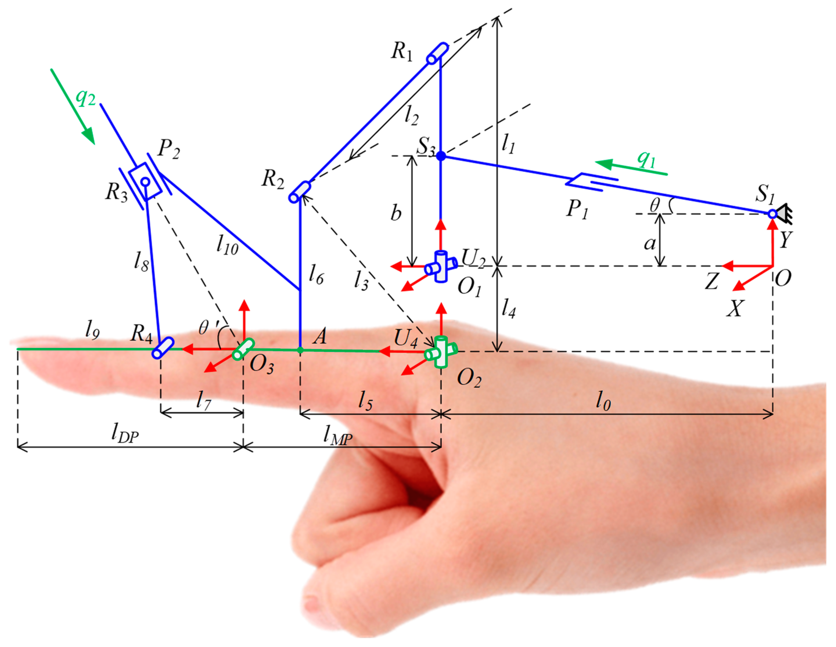
3.1. Mechanical Design

The model of the hand rehabilitation robot is shown in Figure 2, including four finger mechanism and thumb mechanism. In the design process of the four-finger mechanism, the finger bone is taken as a part of the mechanism to meet the demand of self-alignment of the human-machine joint. The active actuated joints are MCP and PIP joints. The DIP and PIP joints are coupled. Moreover, the installation of an additional driver would greatly increase the complexity of the control system and cost, so the active actuation of the DIP joint is not considered. The thumb mechanism can achieve flexion/extension motion and complete the training of the patients’ grasping ability.
The structure of the four modules of four-finger mechanism is similar, so only take the index finger module as an example to introduce, as shown in Figure 3. MCP joint mechanism is mainly composed of a driving part and a four-bar linkage mechanism. The driving parts mainly include motor base, linear actuator, connector, Nitinol wire, connecting rod, finger sleeve, etc. The connection between the motor base and the linear actuator is a spherical joint, and the linear actuator and the connecting rod are connected by a Nitinol wire with a diameter of 0.8 mm. A cross hinge is installed between the base and the drive mechanism. One end of the alloy wire is attached to the connector and the other end is placed into the shaft. There are threaded holes on both sides of the shaft, and the alloy wire is fixed with two set screws. This combined structure expands the range of passive adduction/abduction motion and improves the adaptability of the device. During the flexion motion, the Nitinol wire can store a certain amount of energy and improve the safety of the device, which is a feature of this device.
The PIP joint mechanism mainly includes connecting rod, Bowden wire, finger sleeve, etc., which is a crank-slider mechanism. The driving force comes from a Nitinol wire with a diameter of 1 mm attached to the motor, which can not only provide the strength needed for rehabilitation exercise but also bend and deform itself when spasm occurs. Although this sacrifices the precision of the motion to a certain extent, it can ensure the safety of the patient. In addition, the connecting rods of the mechanism are connected by rivets with threads, which is convenient for disassembly and assembly.
The thumb mechanism, as shown in Figure 4, is composed of a frame, a motor base, a linear actuator, a connecting frame, an adjustable telescopic rod, and a finger sleeve. The support plate can be quickly plugged with the back of the hand, and the back of the hand is provided with an arc-shaped groove. There are two aspects that can be adjusted to adapt to different patients. The first is to adjust the position of the motor base in the arc groove, and the second is to adjust the relative position of the adjustable telescopic rod and the connecting frame. Due to the complex anatomical structure of the thumb, only one motor is arranged to realize the flexion/extension motion.

3.2. Robot Kinematics Analysis and Optimization
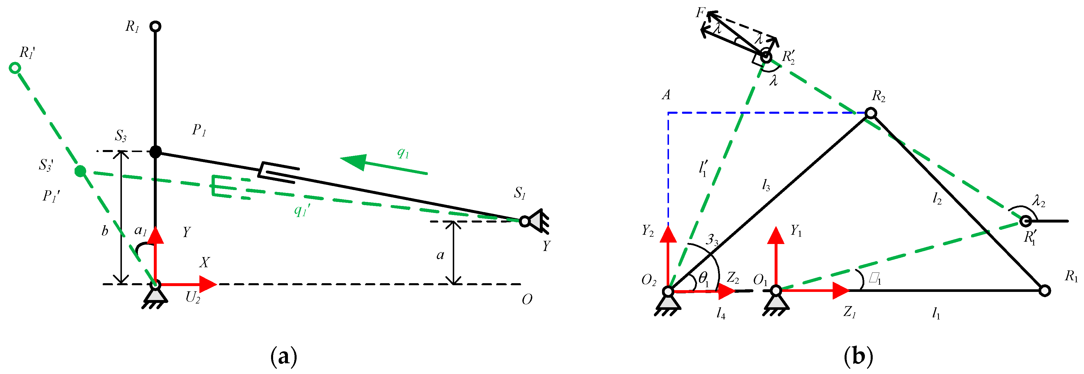
3.2.1. Kinematics

The schematic diagram of the index finger rehabilitation mechanism is shown in Figure 5. The Y-axis of the origin coordinate system {O} is in the vertical direction, passing through the installation end of the linear actuator; the Z-axis is in the horizontal direction, passing through the U2 pair; and the direction of the X-axis is determined by the right-hand rule. The mechanism consists of three parts, which are a four-bar mechanism for input q1 and two four-bar mechanisms for MCP and PIP joints. The functional relationship between the input q1 and the rotation angle of the joint U2 can be obtained from Figure 6a:
( q 1 2 ( b a ) 2 + b sin α 1 ) 2 + ( b cos α 1 a ) 2 = ( q 1 ) 2
The method of complex vector is used to analyze the angle of α1 and MCP joint. The schematic diagram of the mechanism is shown in Figure 6b. The vector expression is l 1 + l 2 = l 3 + l 4 , and the functional relationship is:
α 3 = 2 arctan B ± A 2 + B 2 C 2 A C ,
where
{ A = l 4 l 1 cos α 1 B = l 1 sin α 1 C = A 2 + B 2 + l 3 2 l 2 2 2 l 3 .
For the crank-slider mechanism composed of the PIP joint and the sliding pair, the schematic diagram of the mechanism is shown in Figure 7. According to the cosine law, it can be obtained:
cos ( θ + θ ) = l 7 2 + ( q 2 ) 2 l 8 2 2 l 7 q 2 .
We solve the equation to obtain:
θ = arccos ( l 7 2 + ( q 2 ) 2 l 8 2 2 l 7 q 2 ) θ .
The kinematics expression of the finger mechanism can be obtained by combining the above equations.

3.2.2. Rod Length Optimization Based on Genetic Algorithm

Genetic algorithm is a computational model of biological evolution that simulates natural genetic selection and elimination, with genetics and mutation as the core concepts of the algorithm. The genetic algorithm mainly involves coding (real number coding and binary coding), population size, chromosome length, fitness function and genetic operators (selection operator, crossover operator and mutation operator).
From the knowledge of kinematic anatomy, it can be known that the MCP joint is located at the connection between the palm and the fingers, there is a slip phenomenon during FE motion, and the arrangement space is small. Therefore, the rod length optimization is carried out for the mechanism driving the MCP joint to improve the comprehensive performance of the robot. The constraints in the optimization process mainly include the establishment conditions of the mechanism, the angle magnification factor, and the transmission angle requirements.
  • Conditions for the establishment of the four-bar mechanism;
In order to make the rotation angle of the fingers still meet the needs of rehabilitation training under the premise that the stroke of the linear actuator is small, a double crank mechanism is proposed as the basic configuration. Since the distance between the U2 kinematic pair and the finger MCP joint is relatively close, the frame l4 is used as the shortest rod of the mechanism, according to the conditions for the establishment of the four-bar mechanism:
l max + l 4 l 1 + l 2 + l 3 l max ,
where l max = max ( l 1 , l 2 , l 3 , l 4 ) .
2.
Angle magnification factor;
The drive motor of the MCP joint is placed on the base of the back of the hand. Due to the limitation of the size of the hand, the linear actuator with a large stroke becomes unsuitable. The definition of the angle magnification factor can further constrain the size of the mechanism and make the mechanism compact to meet the needs of motor selection. The factor is defined as the ratio of the rotation angle of the driving motor to the rotation angle of the output member:
k = α 1 α 3 θ 1 [ 0.7 , 1.3 ] .
When the MCP joint rotates at a preset angle of 75°, α 3 θ 1 = 75 ° , the initial and final states of the four-bar mechanism are shown in Figure 8. According to Formula (7), the expression of k can be obtained:
k = α 1 75 ° = 180 ° β 1 β 2 75 ° ,
where
{ β 1 = arcsin ( l 3 sin ( θ 1 + 75 ° ) / l ) β 2 = arccos ( l 2 + l 1 2 l 2 2 2 l l 1 ) l = l 3 2 + l 4 2 2 l 3 l 4 cos ( θ 1 + 75 ° ) θ 1 = arccos ( l 3 2 + ( l 1 + l 4 ) 2 l 2 2 2 l 3 ( l 1 l 4 ) ) .
3.
Transmission angle requirements.
In order to obtain better connecting rod performance, it is necessary to constrain the efficiency of connecting rod transmission force. The transmission angle is an important index to measure the transmission performance of the linkage mechanism. As shown in Figure 3, γ is the transmission angle.
{ γ = δ , δ 90 ° γ = 180 ° δ , δ > 90 ° ,
where
cos δ = l 2 2 + l 3 2 l 1 2 l 4 2 2 l 1 l 4 cos α 1 2 l 2 l 3 .
It can be known that the transmission angle γ is the smallest only when δ is the two positions of the smallest acute angle or the largest obtuse angle. In this case, the corresponding α are 0° and 180°. We can obtain that:
cos δ min = l 2 2 + l 3 2 ( l 1 l 4 ) 2 2 l 2 l 3 cos δ max = l 2 2 + l 3 2 ( l 1 + l 4 ) 2 2 l 2 l 3 γ min = δ min γ min = 180 ° δ max γ min = min ( γ min , γ min ) = f ( l 1 , l 2 , l 3 , l 4 ) .
According to the above formulae, the effect of different rod lengths on force transmission can be judged.
According to the above constraints (double crank mechanism, angular transmission coefficient, and transmission angle), the length of the driving lever l1 is setting to 50 mm. The lengths of connecting rods l2 and l3 are obtained using genetic algorithm. Genetic algorithm (GA) is an optimization algorithm that simulates natural genetic selection [34]. GA mainly involves population size, chromosome length, fitness function and genetic operators (selection operators, crossover operators and mutation operators). The procedure of GA is as follows. A population of chromosomes are initialized randomly, and the fitness of each chromosome in the population is computed. Two chromosomes are selected according to the fitness value. Then, crossover and mutation operations are carried out to obtain new offspring, which are placed in the new population. The selection, crossover and mutation operations will be repeated until the new population is completed. The fitness function is as follows:
f ( x ) = 0.1 * x + k + γ ,
where
x = { 0 ( l max + l 4 > l 1 + l 2 + l 3 l max ) 1 ( l max + l 4 l 1 + l 2 + l 3 l max ) k = { 1 k ( k < 1 ) k 1 ( k > 1 ) γ = γ 40 * π / 180 .
According to the fitness function, the evolution diagram is obtained as shown in the Figure 9.
The number of the evolution generations is 1000, the crossover probability is 0.6, and the mutation probability is 0.01. For the convenience of processing and calculation, all rod lengths should be rounded. The length of the connecting rod l3 is 56 mm, and the length of the connecting rod l2 is 44 mm.

4. Control and Sensing Systems

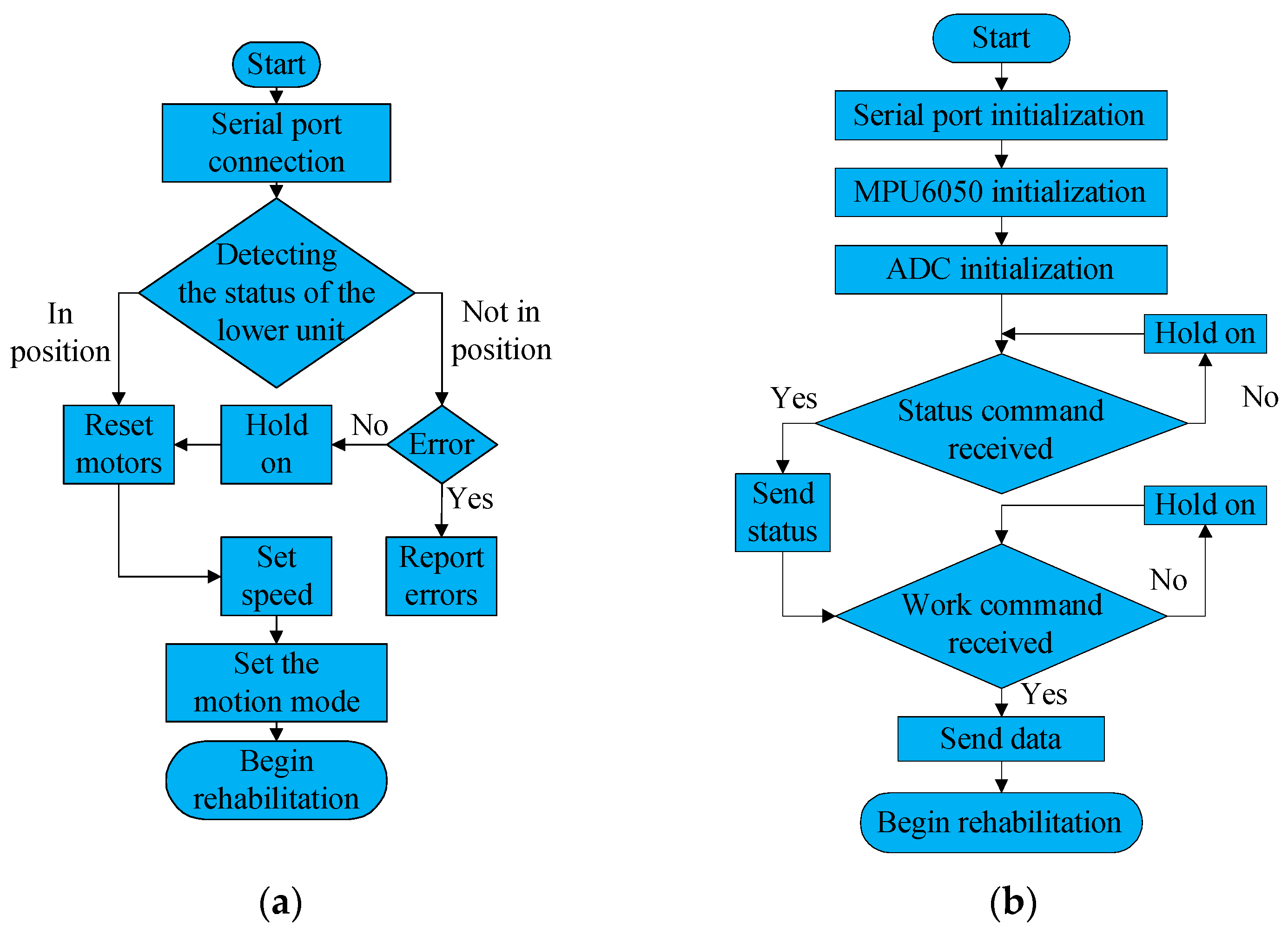
4.1. Software System

The software system includes upper computer software and lower computer software. The upper computer environment is Windows 10, with a 64-bit operating system, and the processor is an Intel Core i7-10750H CPU@2.60GHz, 16.0GB RAM. The software of the upper computer is designed in Qt, and the graphical user interface is designed, as shown in Figure 10. The operation interface has multiple buttons to achieve different functions, including serial search, serial connection, adjusting speed level, motor reset, stop motion, MCP joint flexion/extension, PIP joint flexion/extension, compound flexion/extension, finger pairing, grasping motion and active rehabilitation training, etc. The system has two lower computers, namely the motor controller and the STM32 microcontroller. Both lower computers use serial to communicate with the host computer. In order to prevent program blocking caused by serial interruption, the upper computer adopts dual thread work. The main thread is responsible for processing the information of the motor controller, sending control commands to the motor controller, and the sub-thread is responsible for communicating with the STM32 and receiving the angle value, angular velocity value, angular acceleration value of the gyroscope and the pressure of the film pressure sensor through the serial. After the sub-thread receives the information transmitted by STM32, it will send the data to the main thread, and the main thread will control the motion of the motor according to the data.
According to the required functions, the designed program flow charts of the upper computer and the lower computer are shown in Figure 11a,b, respectively. The upper computer first connects to the serial port and after the connection is successful, it judges the working status of the lower computer, sends the query command to the lower computer, and the lower computer returns the status data. After receiving the status data that the lower computer is in place, the upper computer perform the operations of resetting the motor, setting the speed level, setting the motion mode and starting the rehabilitation training in sequence. The lower computer firstly initializes the serial port, MPU6050 and ADC and then waits to receive the status query command. After it receives the status query command, it starts to wait for the work command. After receiving the work order, it sends data to the upper computer at the interval set by the program.

4.2. Sensing System

With little hand space, there is no room for angle sensors and torque sensors in large sizes, so the sensors in this system include gyroscopes and thin-film pressure sensors. The gyroscope adopts MPU6050, which is a 6-axis motion tracking device designed for the low power, low cost, and high-performance requirements. It integrates a 3-axis MEMS gyroscope, a 3-axis MEMS accelerometer, and a scalable digital motion processor DMP, which can measure the angle and acceleration values in the coordinate system. The membrane pressure sensor uses a file sensitive resistor (FSR), which exhibits a decrease in resistance with an increase in the force applied to the surface. The MPU6050 and the thin film pressure sensor relate to the STM32 single-chip microcomputer, and the IIC communication and ADC acquisition functions of the single-chip microcomputer are used, respectively.

5. Preliminary Experimental Trial of the Robot

5.1. Experimental Platform Construction

The experimental platform includes a finger rehabilitation robot, a remote electric control cabinet, a host computer (PC), a single-chip microcomputer (STM32) and a wrist rest, as shown in Figure 12a. An emergency stop switch has been placed on the cabinet to ensure safety. In order to reduce the burden on the hands, it is necessary to consider the weight of the robot. The connecting rod is made of 6061 aluminum alloy material and the base is made of 8200 resin, taking into account the requirements of light weight and reliability. Considering the difficulty and cost of processing tiny parts, both the connecting rod and the base are processed by 3D printing. In the MCP joint mechanism, a stepped shaft needs to transmit the power between the nitinol wire and the active rod, and it needs to be tapped to hold the nitinol wire. Considering the precision of machining and assembly, this shaft is made of 6061 aluminum alloy and Computerized Numerical Control (CNC) machined.
The power of the PIP joint mechanism of the finger rehabilitation robot comes from the linear actuator in the remote electric control cabinet, which is transmitted to the end effector by the Bowden cable. The remote electric control cabinet includes shell, handle, motor controller, linear actuator, switch button, emergency stop switch, etc. During rehabilitation training, the patient wears the finger rehabilitation robot, puts the arm on the wrist rest, and the staff operates the human–computer interface of the PC to perform passive rehabilitation and active rehabilitation training for the patient.

5.2. Single Finger Experiment

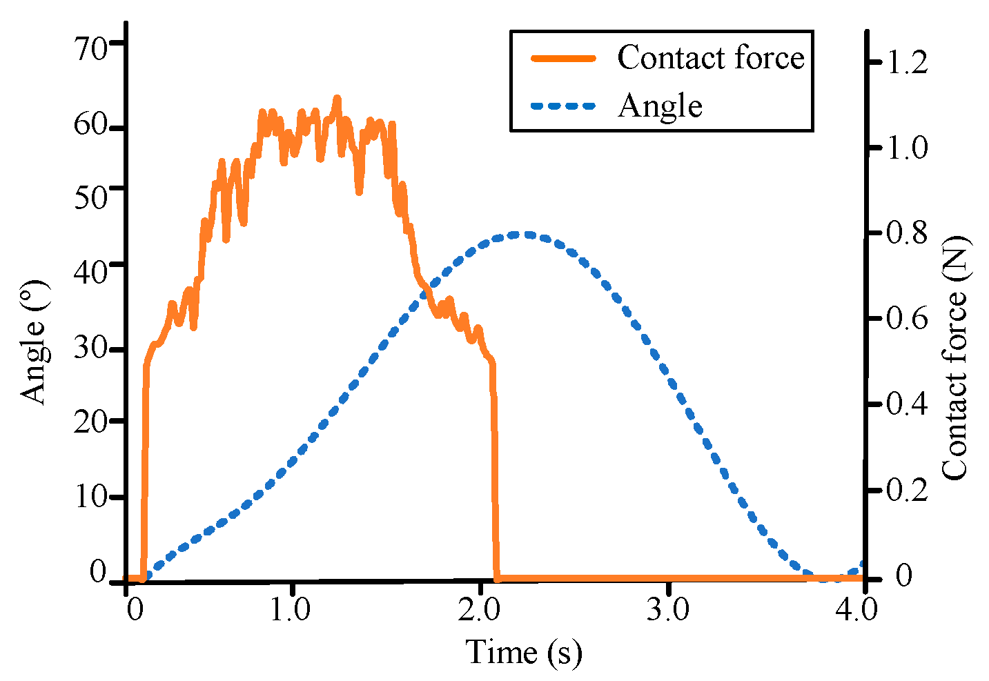
5.2.1. Passive Rehabilitation Experiment

The passive rehabilitation experiment is the validation of the robot’s range of motion (ROM). Passive rehabilitation is mostly used in the early stage of rehabilitation. For example, the continuous passive motion (CPM) can avoid muscle rigidity and atrophy, and stimulate the patient’s nervous system. Because the mechanism of the four fingers is similar, the index finger is used as an example to conduct experiments to verify the accuracy of the control model and mechanical structure. A young male volunteer with an index finger of 100 mm was recruited. Caregiver fixed his hand and the robot together with Velcro. After setting the speed level, the device was started for rehabilitation training. The raw data containing noise collected by the gyroscope and the thin-film pressure sensor is collected by the STM32 microcontroller and sent to the upper computer. After noise reduction processing, it is extracted into a file for subsequent experimental analysis.
Figure 13a shows the relationship between the MCP joint rotation angle and time. According to the MCP joint rotation experiment, the maximum rotation angle can be obtained as 68.0°. According to the free flexion angle of the finger, 70°, the angle accuracy is 97.1%. Figure 13b shows the relationship between the rotation angle of the PIP joint and time. According to the PIP joint rotation experiment, the maximum rotation angle can be obtained as 78.5°. According to the designed PIP joint rehabilitation angle, 80°, the angle accuracy is 98.1%. Theoretically, the maximum flexion angle of the finger PIP joint is 110°, but due to the occupancy of the Velcro and the pressure on the skin, it is impossible for the machine to reach this angle. A flexion angle of 80° can accomplish the established rehabilitation goals. According to Figure 13a,b, it can be seen that the follow-up performance of the mechanism is good.

5.2.2. Active Rehabilitation Experiment

Active rehabilitation is used in the middle and late stages of rehabilitation to sense the patient’s motion intention, and the robot follows the fingers to move according to the motion intention. The film pressure sensor can collect the contact force between the finger and the robot, and judge the patient’s motion intention according to the pressure value. According to the different rehabilitation status of the patient, the pressure threshold can be set as needed. When the pressure value is greater than the pressure threshold, the robot drives the finger to perform a flexing motion, and when the pressure value is less than or equal to the pressure threshold, the robot drives the finger to perform a stretching motion. In this experiment, the pressure threshold was set to 0.5 N. The active rehabilitation experiment was carried out according to the set motion mode, and the experimental curve obtained is shown in Figure 14. It can be seen that when the contact force is greater than 0.5 N, the robot drives the fingers to start the flexion motion. When the contact force begins to decrease, eventually less than 0.5 N, the robot drives the fingers to start the extension motion.

5.3. Grasp Ability Experiment

The function and accuracy of the finger rehabilitation robot have been verified in the passive rehabilitation experiments and active rehabilitation experiments in the previous section. Next, the grasp ability experiment was carried out to verify the ability of the robot assisting hand to complete activities of daily living (ADL). Hand operation training (OT) is a purposeful task-based rehabilitation training in a real scene, and patients can perform functional rehabilitation training. ADL is an important element of OT, and the most representative action is grasping motion. Some simple verifications are currently performed. According to the object being grasped, the required parameter matrix is sent from the host computer to the motor controller, and the robot is controlled to drive the hand to grasp, specifically, including pinching paper, handling a bottle, grasping an orange, and picking up a Rubik’s cube (Figure 15). Carry out grasping experiments on four objects of different shapes and sizes to verify the degree to which the robot can achieve grasping actions and adapt to objects of different shapes. In this experiment, a thin-film pressure sensor is used to detect the pressure between the finger and the object, and the required pressure is different for different objects. When it is detected that the pressure reaches the required value, the robot stops moving, maintains the grasping action, and the dangerous pressure threshold is set. Once the pressure reaches this value, the robot will immediately return to its original position and a danger prompt will pop up on the host computer.

6. Conclusions and Future Work

In this article, a hand rehabilitation exoskeleton is proposed to achieve independent joint actuation of the finger at 9 DoF, possessing sufficient precision of operation. An experiment is carried out to research the phenomenon of MCP joint offset, and it is used in structural design. The robot includes a four-finger mechanism and a thumb mechanism. In the former, there are four modules with a similar structure, and each of them has two DoF to perform flexion/extension motions of the MCP and PIP joints. In the latter, there is one active DoF to achieve flexion/extension motions of the thumb, and there is a curved rail to adjust the abduction angle to improve the adaptation of the robot. Two kinds of flexible elements, Nitinol wires and springs, are adopted, improving the robot’s adaptability, ensuring patient safety and avoiding secondary injuries. The Nitinol wire also allows the robot to perform flexion/extension with a slight adduction/abduction, which is in accordance with the laws of human motion. The robot can achieve long-distance power transmission with the cable-driven approach, which alleviates the weight on the wearer. Finally, the experiments are conducted to validate the robot’s ROM and the ability assisting hand to complete ADL. The theoretical analysis and experimental results indicate that the robot can realize passive and active rehabilitation and meet the patient’s rehabilitation requirements.
The thumb of a human has 5 DoF, but the robot has only one active and one passive DoF, which limits the effectiveness of thumb rehabilitation. In the future, improvements are to be made on the whole system from the optimization of the mechanism, including reducing the weight of the robot and designing a better mechanism for thumb rehabilitation.

Author Contributions

Conceptualization, J.D., H.W. and J.N.; formal analysis, J.D. and Y.T.; investigation, B.C.; methodology, J.D. and D.Z.; project administration, H.W.; software, D.Z. and Y.Z.; supervision, B.C.; validation, D.Z., Y.Z. and Y.T.; visualization, D.Z. and Y.Z.; writing—original draft, J.D. and J.N.; writing—review and editing, H.W. and J.N. All authors have read and agreed to the published version of the manuscript.

Funding

This research was funded by the National Natural Science Foundation of China (U1913216) and the Science and Technology (S&T) Program of Hebei, (19211820D, E2020103001 and 20371801D).

Informed Consent Statement

Informed consent was obtained from all subjects involved in the study.

Acknowledgments

This research is partially supported by Shanghai Clinical Research Center for Aging and Medicine (19MC1910500).

Conflicts of Interest

The authors declare no conflict of interest.

References

  1. Feigin, V.L.; Nguyen, G.; Cercy, K.; Johnson, C.O.; Alam, T.; Parmar, P.G.; Abajobir, A.A.; Abate, K.H.; Abd-Allah, F.; Abejie, A.N.; et al. Global, regional, and country-specific lifetime risks of stroke, 1990 and 2016. N. Engl. J. Med. 2018, 379, 2429–2437. [Google Scholar] [CrossRef] [PubMed]
  2. WHO. World Health Statistics 2021: Monitoring Health for the SDGs, Sustainable Development Goals; Licence: CC BY-NC-SA 3.0 IGO; World Health Organization: Geneva, Switzerland, 2021. [Google Scholar]
  3. Jia, J. Hand Function Rehabilitation, 1st ed.; Publishing House of Electronics Industry: Beijing, China, 2019. [Google Scholar]
  4. Suarez, M.; Rendon-Velez, E. An overview of robotic/mechanical devices for post-stroke thumb rehabilitation. Disabil. Rehabil. Assist. Technol. 2018, 13, 683–703. [Google Scholar] [CrossRef] [PubMed]
  5. Noronha, B.; Accoto, D. Exoskeletal devices for hand assistance and rehabilitation: A comprehensive analysis of state-of-the-art technologies. IEEE Trans. Med. Robot. Bionics 2021, 3, 525–538. [Google Scholar] [CrossRef]
  6. Hwang, C.; Seong, J.; Son, D.S. Individual finger synchronized robot-assisted hand rehabilitation in subacute to chronic stroke: A prospective randomized clinical trial of efficacy. Clin. Rehabil. 2021, 26, 696–704. [Google Scholar] [CrossRef] [PubMed]
  7. Orlando, F.; Behera, L.; Dutta, A.; Saxena, A. Optimal design and redundancy resolution of a novel robotic two-fingered exoskeleton. IEEE Trans. Med. Robot. Bionics 2020, 2, 59–75. [Google Scholar] [CrossRef]
  8. Kawasaki, H.; Ito, S.; Ishigure, Y.; Nishimoto, Y.; Aoki, T.; Mouri, T.; Sakaeda, H.; Abe, M. Development of a hand motion assist robot for rehabilitation therapy by patient self-motion control. In Proceedings of the 2007 IEEE 10th International Conference on Rehabilitation Robotics, Noordwijk, The Netherlands, 13–15 June 2007. [Google Scholar]
  9. Singh, N.; Saini, M.; Anand, S.; Kumar, N.; Srivastava, M.V.; Mehndiratta, A. Robotic exoskeleton for wrist and fingers joint in post-stroke neuro-rehabilitation for low-resource settings. IEEE Trans. Neural Syst. Rehabil. Eng. 2019, 27, 2369–2377. [Google Scholar] [CrossRef] [PubMed]
  10. Sandoval-Gonzalez, O.; Jacinto-Villegas, J.; Herrera-Aguilar, I.; Portillo-Rodiguez, O.; Tripicchio, P.; Hernandez-Ramos, M.; Flores-Cuautle, A.; Avizzano, C. Design and development of a hand exoskeleton robot for active and passive rehabilitation. Int. J. Adv. Robot. Syst. 2016, 13, 66. [Google Scholar] [CrossRef] [Green Version]
  11. Shields, B.L.; Main, J.A.; Peterson, S.W.; Strauss, A.M. An anthropomorphic hand exoskeleton to prevent astronaut hand fatigue during extravehicular activities. IEEE Trans. Syst. Man Cybern. Part A Syst. Hum. 1997, 27, 668–673. [Google Scholar] [CrossRef]
  12. Hsu, T.H.; Chiang, Y.C.; Chan, W.T.; Chen, S.J. A finger exoskeleton robot for finger movement rehabilitation. Inventions 2017, 2, 12. [Google Scholar] [CrossRef] [Green Version]
  13. Carbone, G.; Gerding, E.C.; Corves, B.; Cafolla, D.; Russo, M.; Ceccarelli, M. Design of a two-dofs driving mechanism for a motion-assisted finger exoskeleton. Appl. Sci. 2020, 10, 2619. [Google Scholar] [CrossRef]
  14. Jo, I.; Park, Y.; Lee, J.; Bae, J. A portable and spring-guided hand exoskeleton for exercising flexion/extension of the fingers. Mech. Mach. Theory 2019, 135, 176–191. [Google Scholar] [CrossRef]
  15. Sun, N.; Li, G.; Cheng, L. Design and validation of a self-aligning index finger exoskeleton for post-stroke rehabilitation. IEEE Trans. Neural Syst. Rehabil. Eng. 2021, 29, 1513–1523. [Google Scholar] [CrossRef] [PubMed]
  16. Li, G.; Cheng, L.; Sun, N. Design, manipulability analysis and optimization of an index finger exoskeleton for stroke rehabilitation. Mech. Mach. Theory 2022, 167, 104526. [Google Scholar] [CrossRef]
  17. Li, C.; Yan, Y.; Ren, H. Compliant finger exoskeleton with telescoping super-elastic transmissions. J. Intell. Robot. Syst. 2020, 100, 435–444. [Google Scholar] [CrossRef]
  18. Agarwal, P.; Deshpande, A. Subject-specific assist-as-needed controllers for a hand exoskeleton for rehabilitation. IEEE Robot. Autom. Lett. 2018, 3, 508–515. [Google Scholar] [CrossRef]
  19. Li, J.; Wang, S.; Wang, J.; Zheng, R.; Zhang, Y.; Chen, Z. Development of a hand exoskeleton system for index finger rehabilitation. Chin. J. Mech. Eng. 2012, 25, 223–233. [Google Scholar] [CrossRef]
  20. Cheng, L.; Chen, M.; Li, Z. Design and control of a wearable hand rehabilitation robot. IEEE Access 2018, 6, 74039–74050. [Google Scholar] [CrossRef]
  21. Zhang, F.; Yang, L.; Fu, Y. Design of a novel elastic torque sensor for hand injuries rehabilitation based on bowden cable. IEEE Trans. Instrum. Meas. 2018, 68, 3184–3192. [Google Scholar] [CrossRef]
  22. Pu, S.W.; Pei, Y.C.; Chang, J.Y. Decoupling finger joint motion in an exoskeletal hand: A design for robot-assisted rehabilitation. IEEE Trans. Ind. Electron. 2020, 67, 686–697. [Google Scholar] [CrossRef]
  23. Marconi, D.; Baldoni, A.; McKinney, Z.; Cempini, M.; Crea, S.; Vitiello, N. A novel hand exoskeleton with series elastic actuation for modulated torque transfer. Mechatronics 2019, 61, 69–82. [Google Scholar] [CrossRef]
  24. Jo, I.; Bae, J. A force-controllable compact actuator module for a wearable hand exoskeleton. In Proceedings of the 19th World Congress the International Federation of Automatic Control, Cape Town, South Africa, 24–29 August 2014. [Google Scholar]
  25. Tran, P.; Jeong, S.; Wolf, S.L.; Desai, J.P. Patient-specific, voice-controlled, robotic flexotendon glove-ii system for spinal cord injury. IEEE Robot. Autom. Lett. 2020, 5, 898–905. [Google Scholar] [CrossRef]
  26. Wang, J.; Liu, Z.; Fei, Y. Design and testing of a soft rehabilitation glove integrating finger and wrist function. J. Mech. Robot. 2019, 11, 011015. [Google Scholar] [CrossRef]
  27. Bützer, T.; Lambercy, O.; Arata, J.; Gassert, R. Fully wearable actuated soft exoskeleton for grasping assistance in everyday activities. Soft Robot. 2021, 8, 128–143. [Google Scholar] [CrossRef] [PubMed]
  28. Cappello, L.; Meyer, J.T.; Galloway, K.C.; Peisner, J.D.; Granberry, R.; Wagner, D.A.; Walsh, C.J. Assisting hand function after spinal cord injury with a fabric-based soft robotic glove. J. NeuroEng. Rehabil. 2018, 15, 59. [Google Scholar] [CrossRef]
  29. Yap, H.K.; Lim, J.H.; Nasrallah, F.; Goh, J.C.; Yeow, R.C. A soft exoskeleton for hand assistive and rehabilitation application using pneumatic actuators with variable stiffness. In Proceedings of the 2015 IEEE International Conference on Robotics and Automation (ICRA), Seattle, WA, USA, 26–30 May 2015. [Google Scholar]
  30. Li, J.; Zhang, Z.; Zhang, L.; Tao, C.; Ji, R.; Fan, J. Review of the kinematic compatibility design of hand exoskeletons. J. Shanghai Jiaotong Univ. 2018, 52, 729–742. [Google Scholar] [CrossRef]
  31. Santos, V.J.; Valero-Cuevas, F.J. Reported anatomical variability naturally leads to multimodal distributions of Denavit-Hartenberg parameters for the human thumb. IEEE Trans. Biomed. Eng. 2006, 53, 155–163. [Google Scholar] [CrossRef]
  32. Zafar, U.; Rahman, S.U.; Hamid, N.; Ahsan, J.; Zafar, N. Correlation between height and hand size, and predicting height on the basis of age, gender and hand size. J. Med. Sci. 2017, 25, 425–428. [Google Scholar]
  33. Huo, S.; Fan, S.; Zhao, C. Measurement of fingers’ width and length of every segment in human. Prog. Anat. Sci. 2003, 9, 326–328. [Google Scholar] [CrossRef]
  34. Katoch, S.; Chauhan, S.S.; Kumar, V. A review on genetic algorithm: Past, present, and future. Multimed. Tools Appl. 2021, 80, 8091–8126. [Google Scholar] [CrossRef]
Figure 1. The diagram of (a) the position of the markers pasted onto subject and (b) the proximal phalanx sliding distance variation for different flexion angles of MCP joint.
Machines 10 01211 g001
Figure 2. The model of the hand rehabilitation robot.
Machines 10 01211 g002
Figure 3. The MCP joint and PIP joint mechanisms of the index finger.
Machines 10 01211 g003
Figure 4. The thumb mechanism.
Machines 10 01211 g004
Figure 5. The schematic diagram of the index finger rehabilitation mechanism.
Machines 10 01211 g005
Figure 6. The schematic diagrams of the (a) input mechanism and (b) MCP joint mechanism.
Machines 10 01211 g006
Figure 7. The schematic diagrams of the PIP joint mechanism.
Machines 10 01211 g007
Figure 8. The schematic diagrams of two different positions of the MCP joint mechanism.
Machines 10 01211 g008
Figure 9. The fitness function value for the number of generations.
Machines 10 01211 g009
Figure 10. The graphical user interface designed by Qt.
Machines 10 01211 g010
Figure 11. Program Flowchart of (a) upper and (b) lower computer.
Machines 10 01211 g011
Figure 12. The (a) overview of the experimental platform and (b) the prototype of the hand rehabilitation robot.
Machines 10 01211 g012
Figure 13. The comparison diagram of the experimental values and the target values for (a) MCP joints and (b) PIP joints.
Machines 10 01211 g013
Figure 14. The comparison diagram of the angle values and the contact force values.
Machines 10 01211 g014
Figure 15. Grasp ability experiment: (a) Pinching paper; (b) Grasping a cup; (c) Picking an orange; (d) Handling a Rubik’s cube.
Machines 10 01211 g015
Table 1. Comparison of Hand Rehabilitation Robots.
NameTypeActive
DoF
TransmissionActuatorDecoupling of Joints
This paperHybrid9Linkage/cableLinear motorYes
Amadeo [6]Rigid5LinkageDC motorNo
Two-Fingered
Exoskeleton [7]
Rigid7LinkageServo motorYes
Hand motion assist robot [8]Rigid18Linkage/gearServo motorYes
Robotic
Exoskeleton [9]
Rigid1Linkage/gearDC motorNo
ExoK’ab [10]Rigid8Linkage/gearDC motorYes
Spring-guided
exoskeleton [14]
Hybrid1Linkage/springLinear motorNo
WIFRE [15,16]Hybrid3Linkage/cableDC motorYes
Two-finger
exoskeleton [17]
Hybrid5Linkage/cableServo motorYes
Maestro [18]Hybrid7Linkage/cableDC motorYes
Hand exoskeleton [23,24]Hybrid7Linkage/SEADC motorYes
FLEXotendon Glove-II [25]Soft4CableBiomimetic tendonNo
Soft glove [26]Soft6-Pneumatic
actuator
No
RELab tenoexo [27]Soft5SpringDC motorNo
Soft robotic glove [28]Soft5BladderAir PumpNo
ExoGlove [29]Soft5-Pneumatic actuatorNo
Table 2. The requirements that the robot needs to meet.
RequirementsRanges
Link length of the proximal phalange37.07–51.48 mm
Link length of the middle phalange18.09–24.64 mm
Motion range of the active MCP f/e70°
Motion range of the passive MCP a/a15°
Motion range of the active PIP f/e80°
Publisher’s Note: MDPI stays neutral with regard to jurisdictional claims in published maps and institutional affiliations.

