
A Novel Suppression Method for Low-Order Harmonics Causing Resonance of Induction Motor


Abstract
:1. Introduction
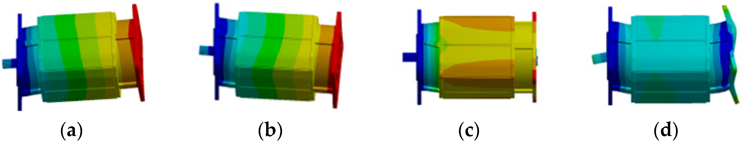
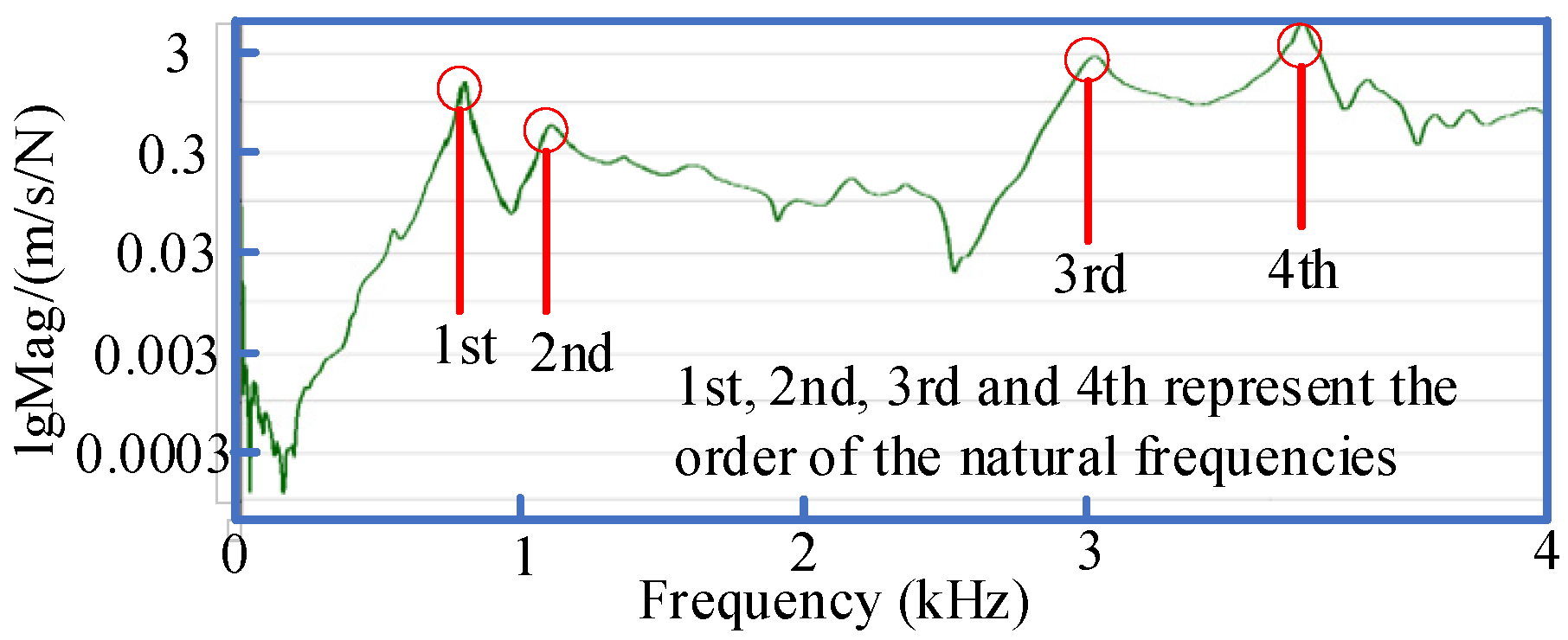
2. Simulation and Measurement for the Natural Frequency of IM
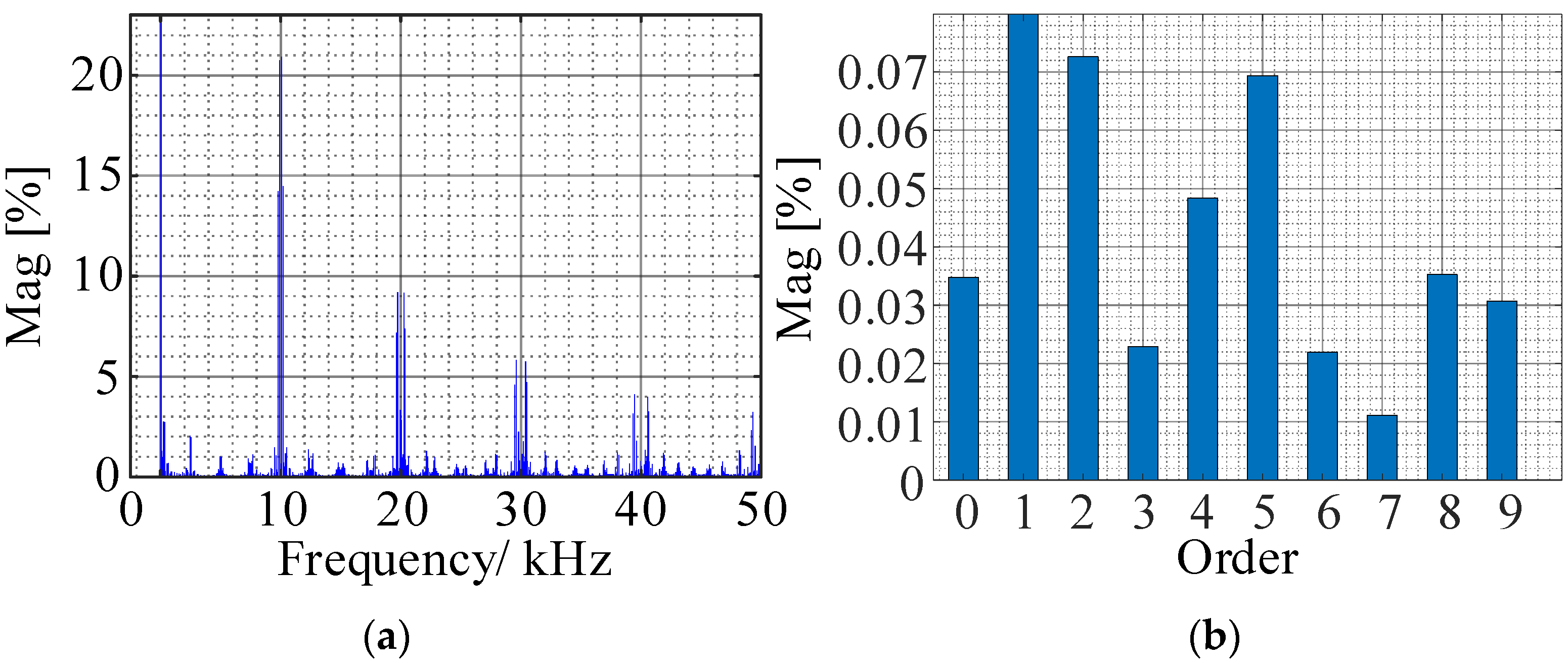
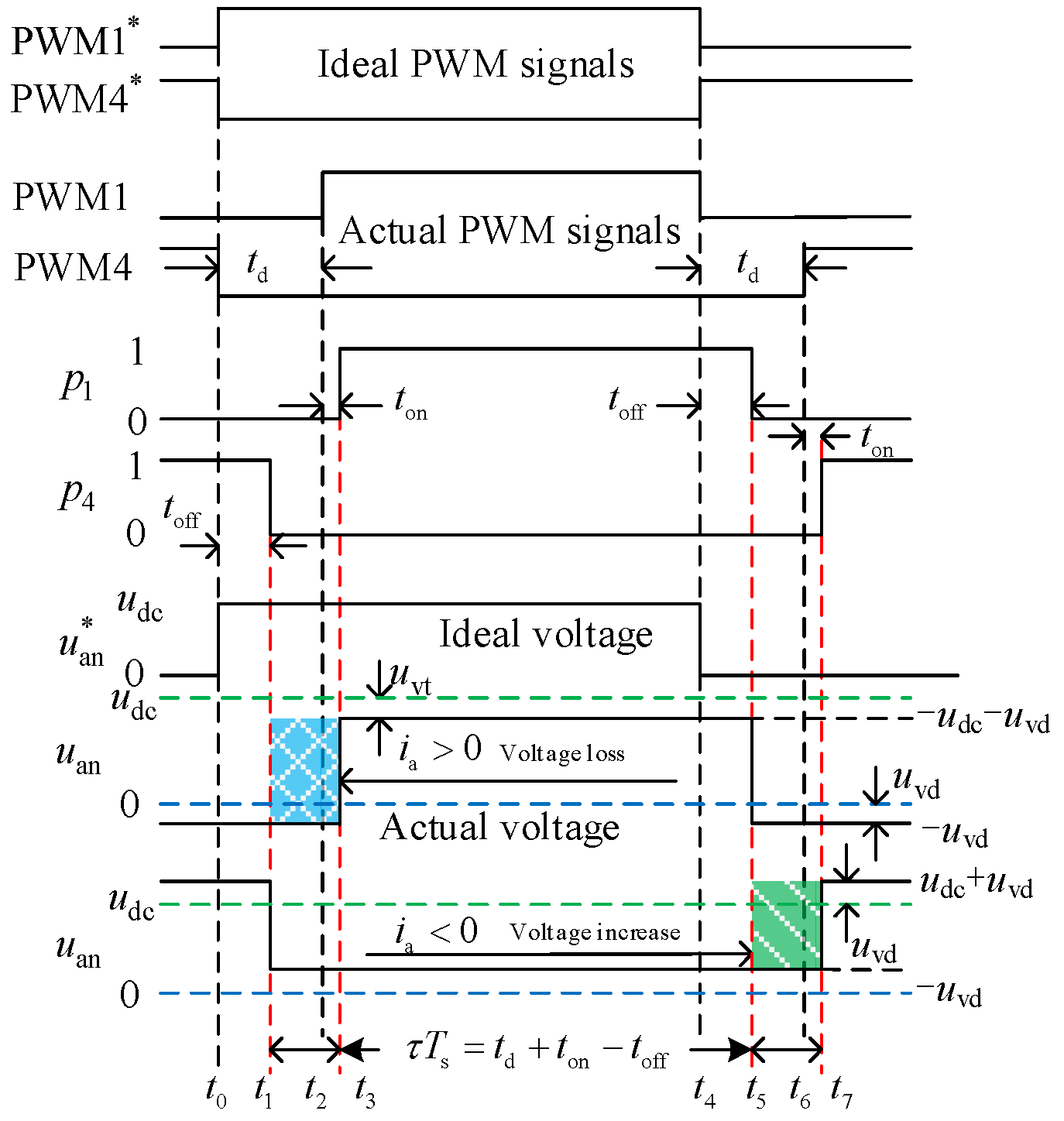
3. Analysis of Harmonic Characteristics Caused by Nonlinear Factors
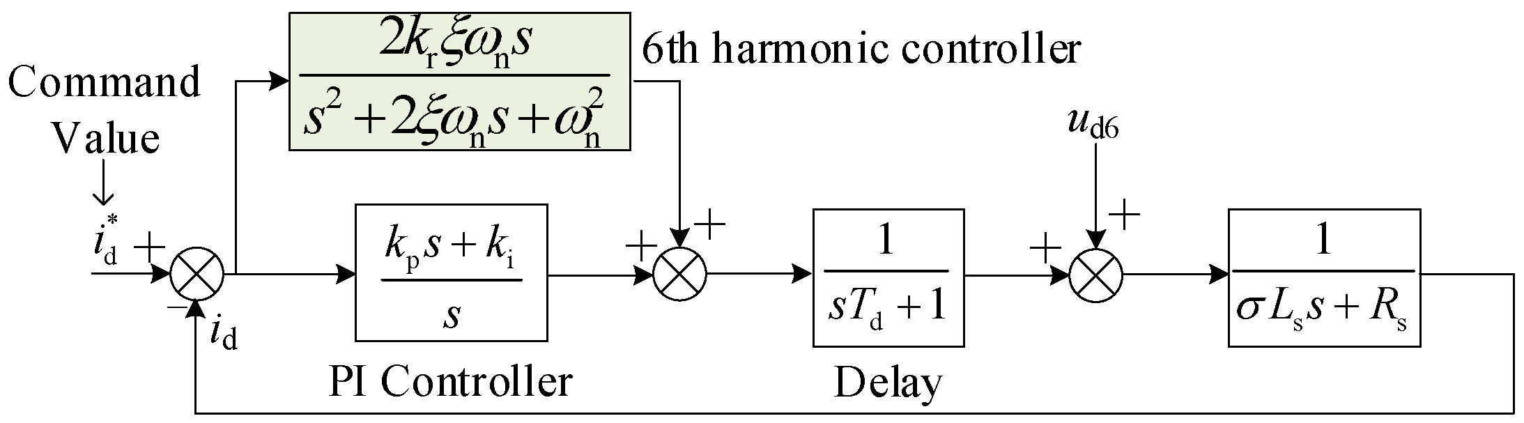
4. Design of Current Loop Controller with 6th Harmonic Suppression
4.1. The Parameters Design of PI Controller
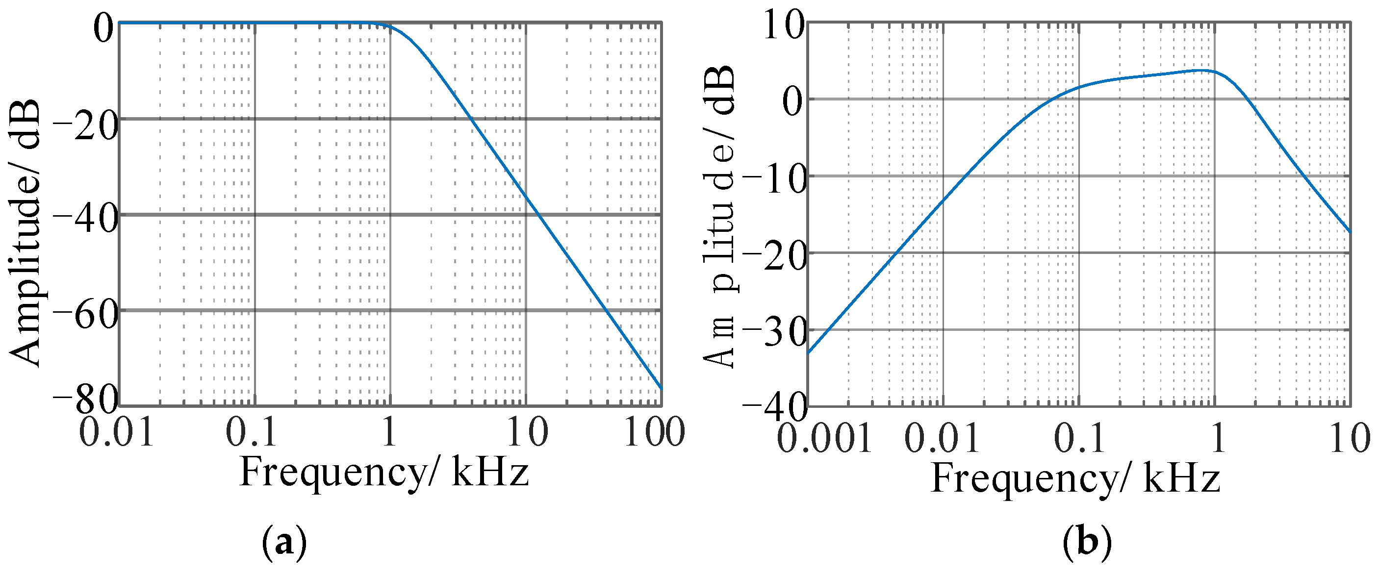
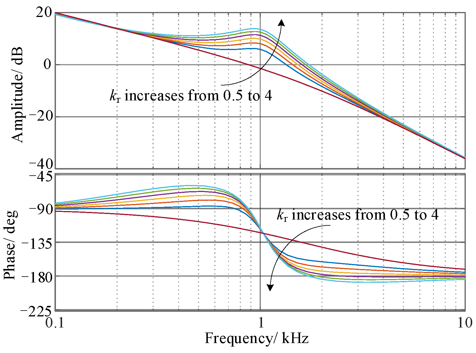
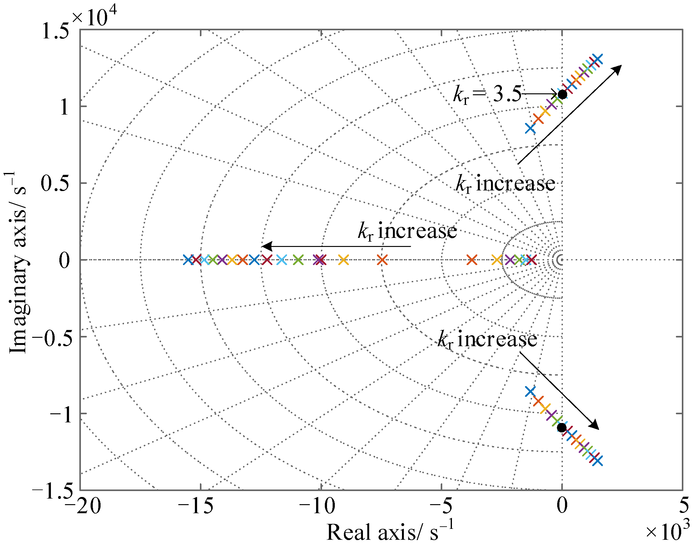
4.2. The Parameters Design of Resonance Controller
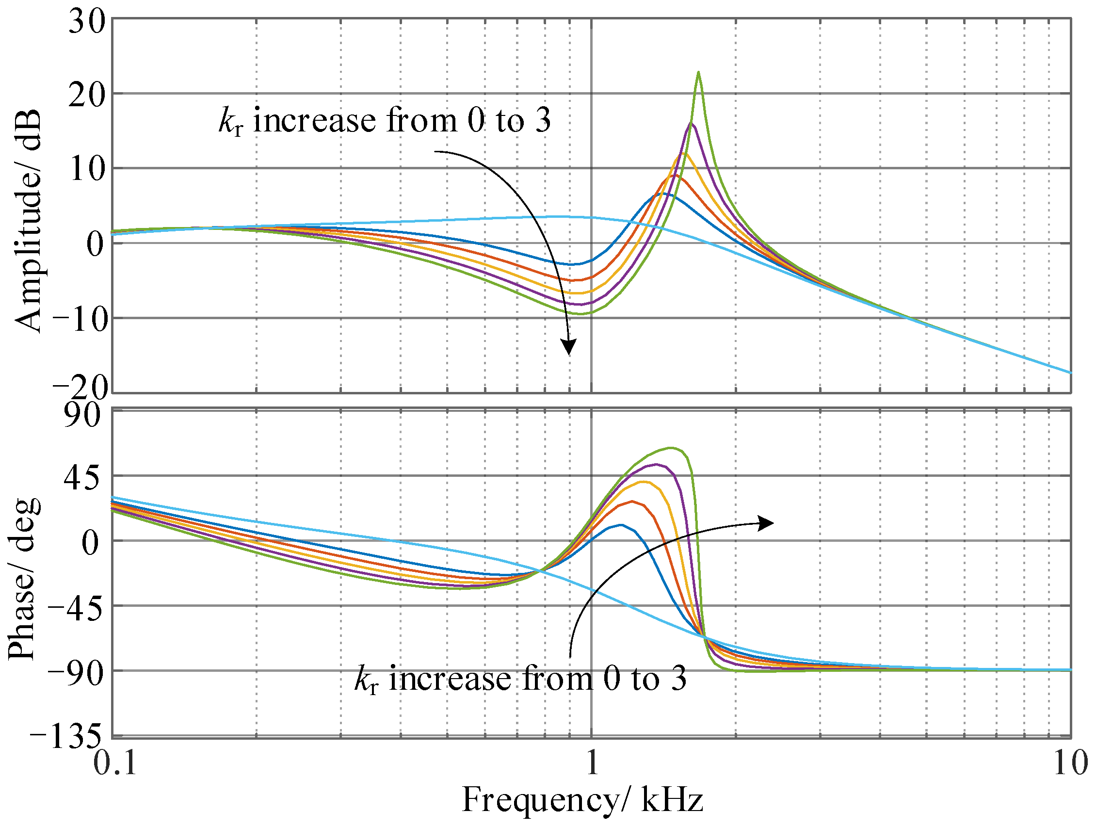
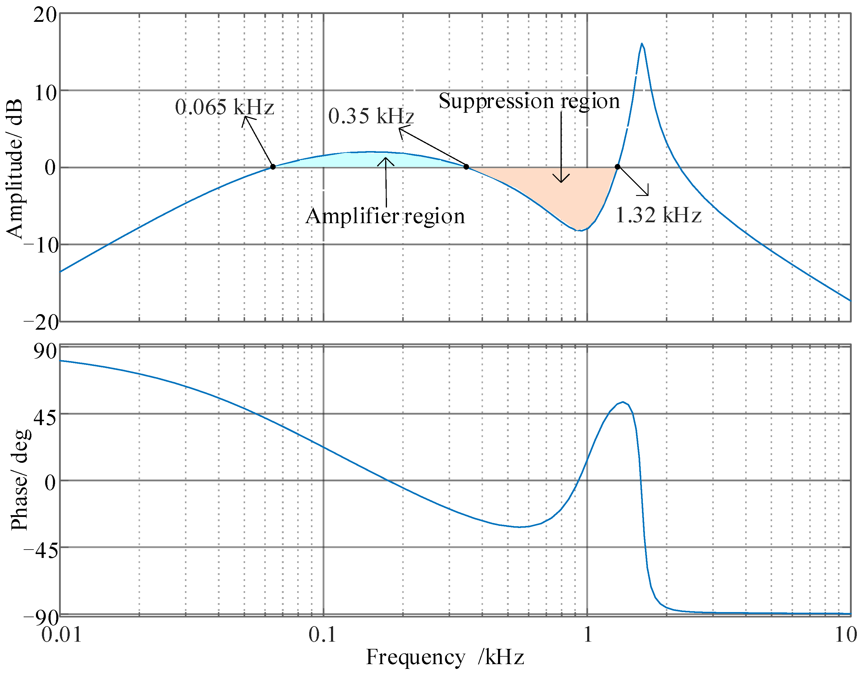
4.3. Analysis of the Resonance Controller under Frequency Variation
5. Simulation Results
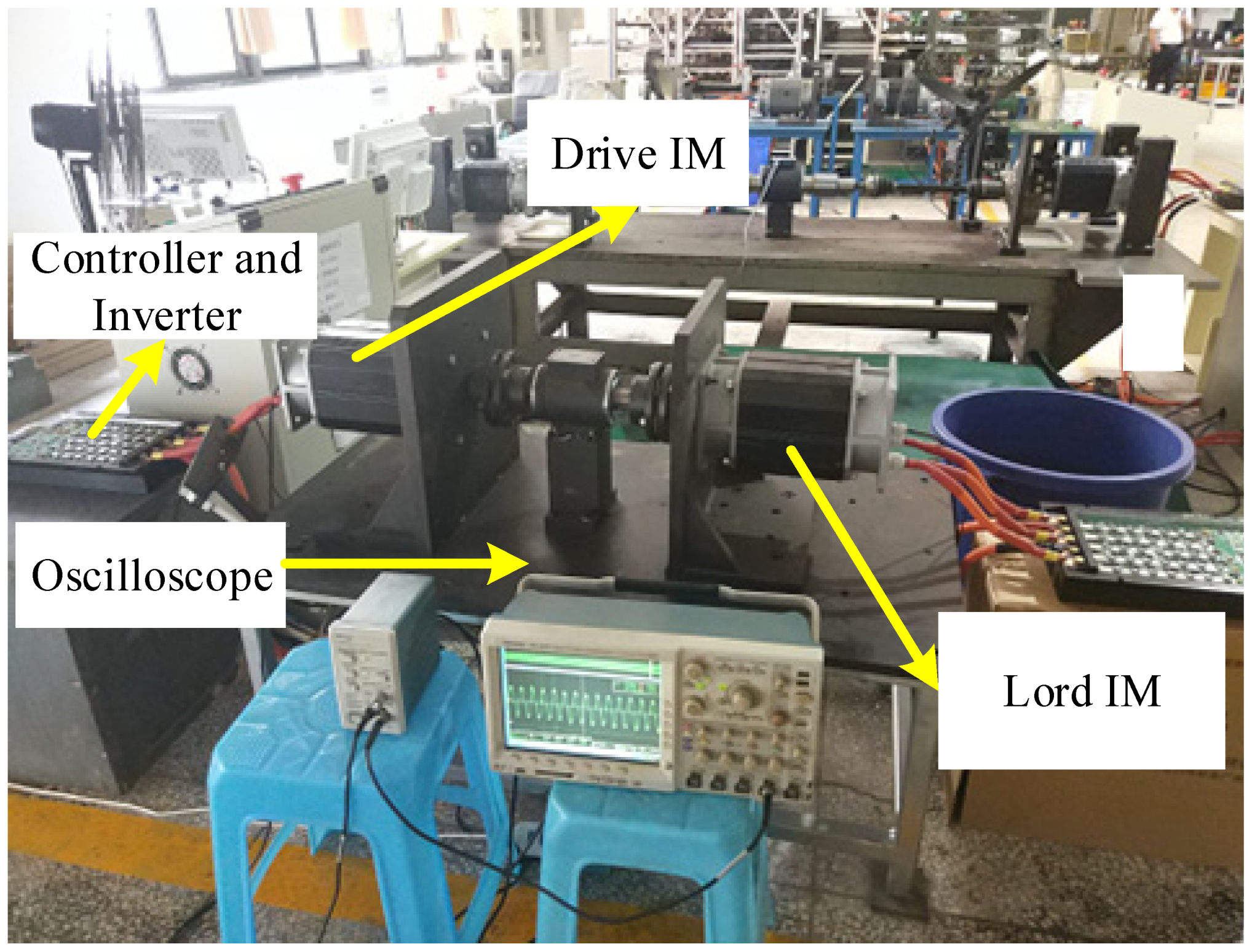
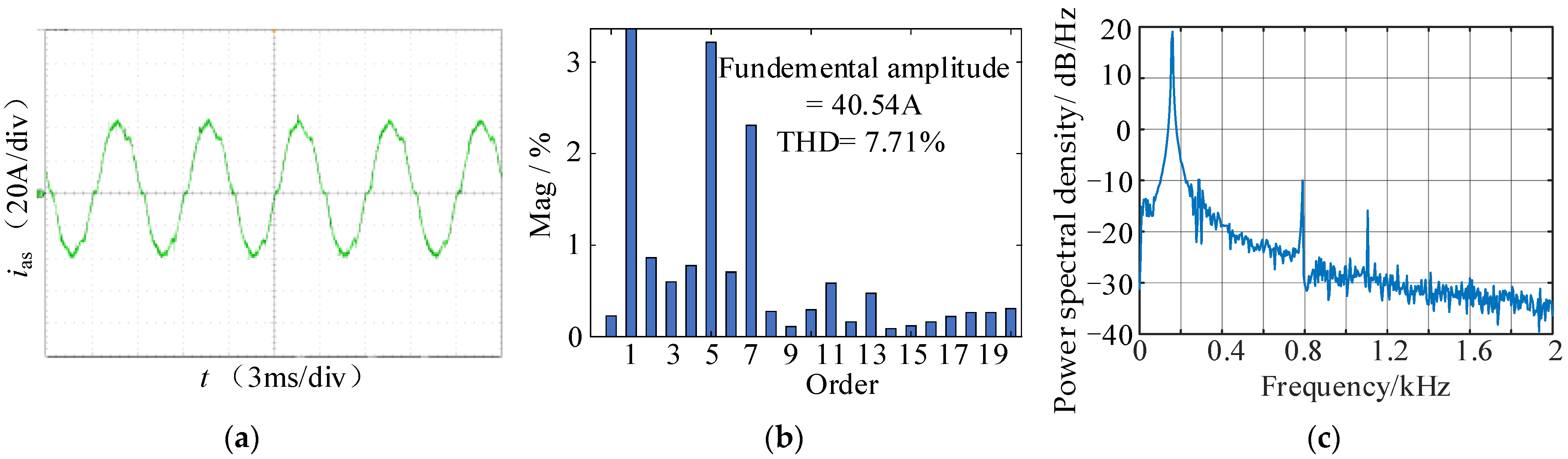
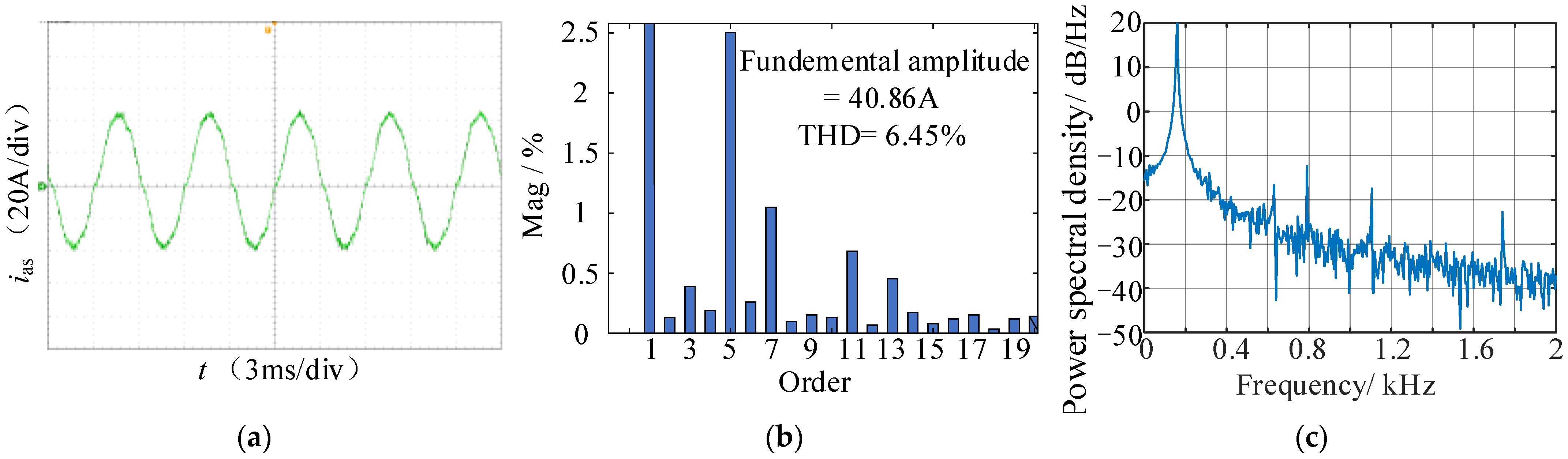
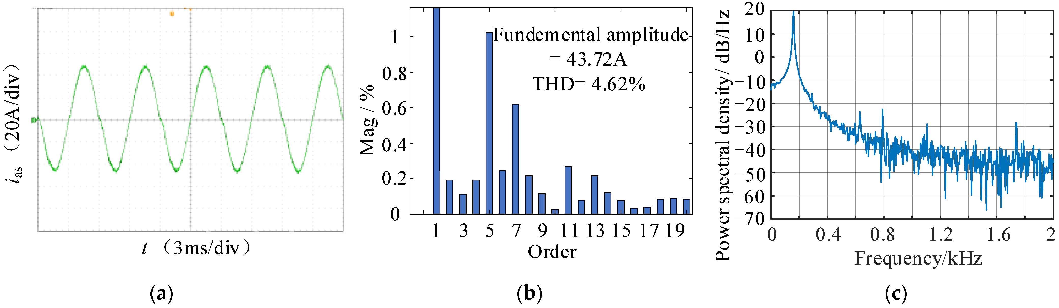
6. Experimental Results
7. Conclusions
- (1)
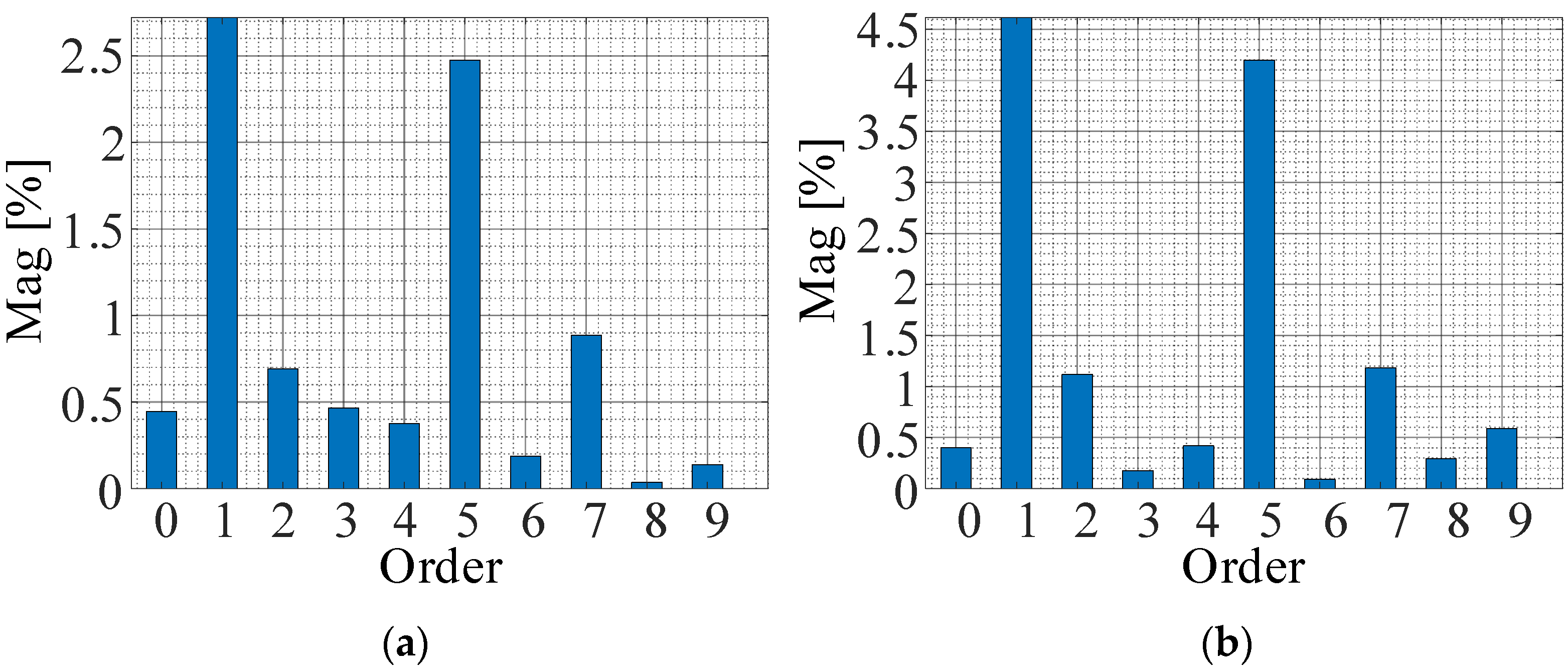
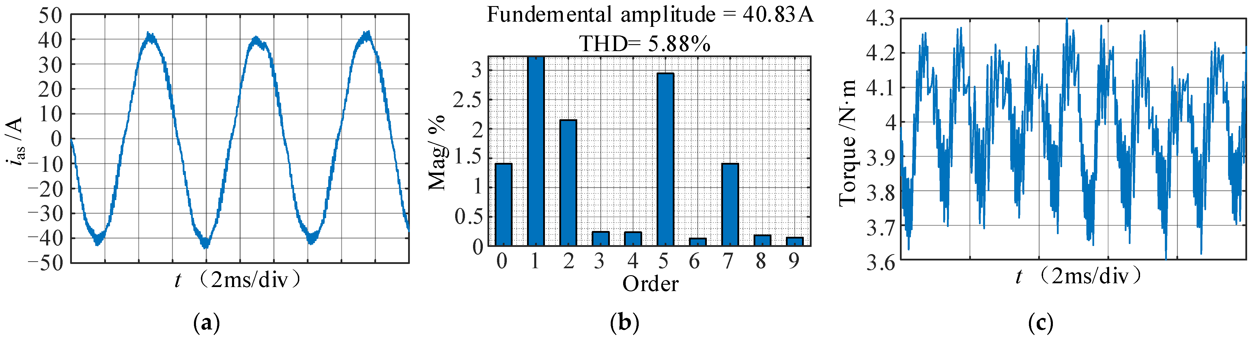
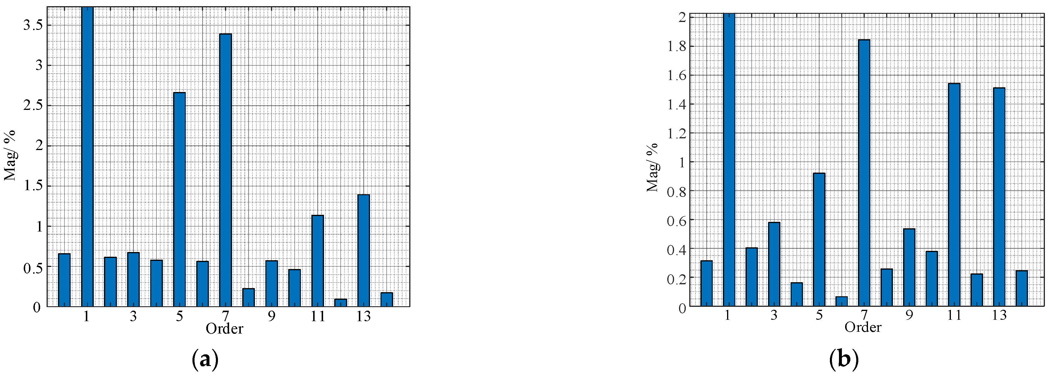
- The dead time and the conduction voltage drop of the switching tube and body diode will produce nonlinear errors in the inverter output voltage. The current PI controller based on rotor flux orientation cannot suppress the 5th and 7th harmonic distortion of the stator current caused by the nonlinear voltage;
- (2)
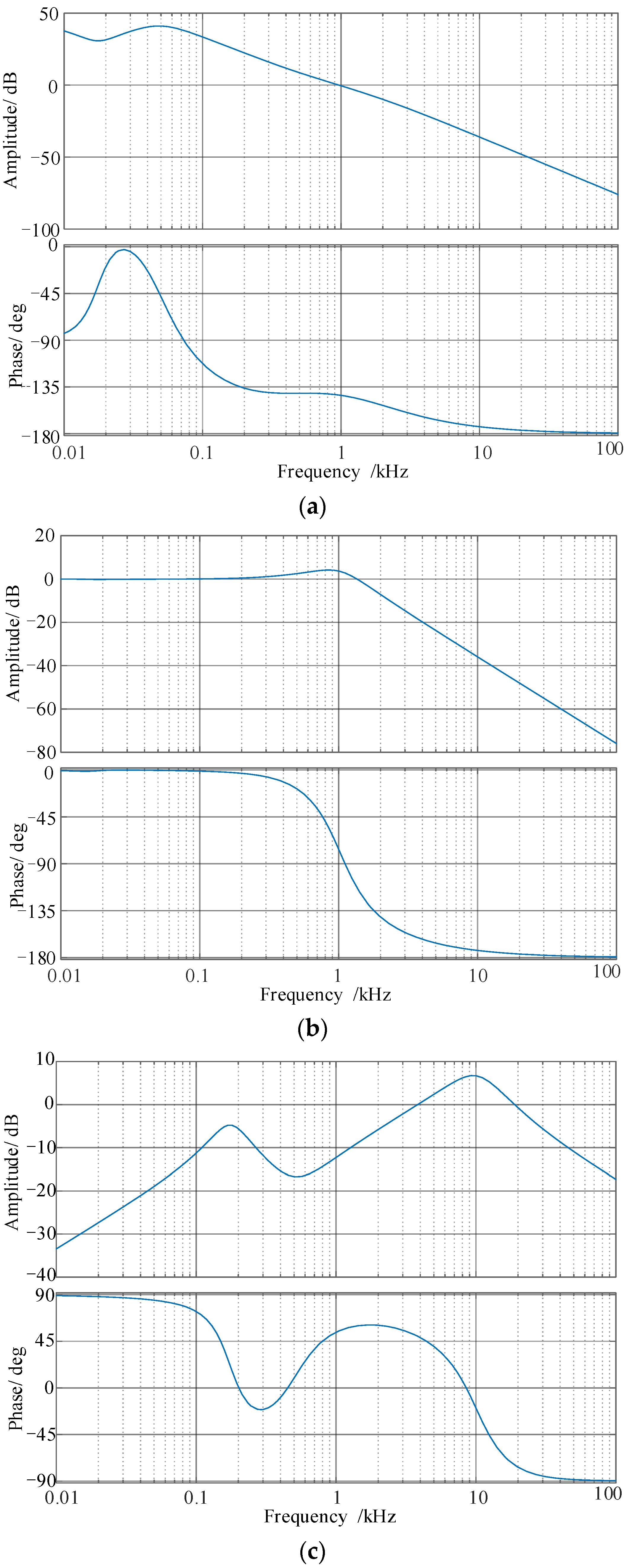
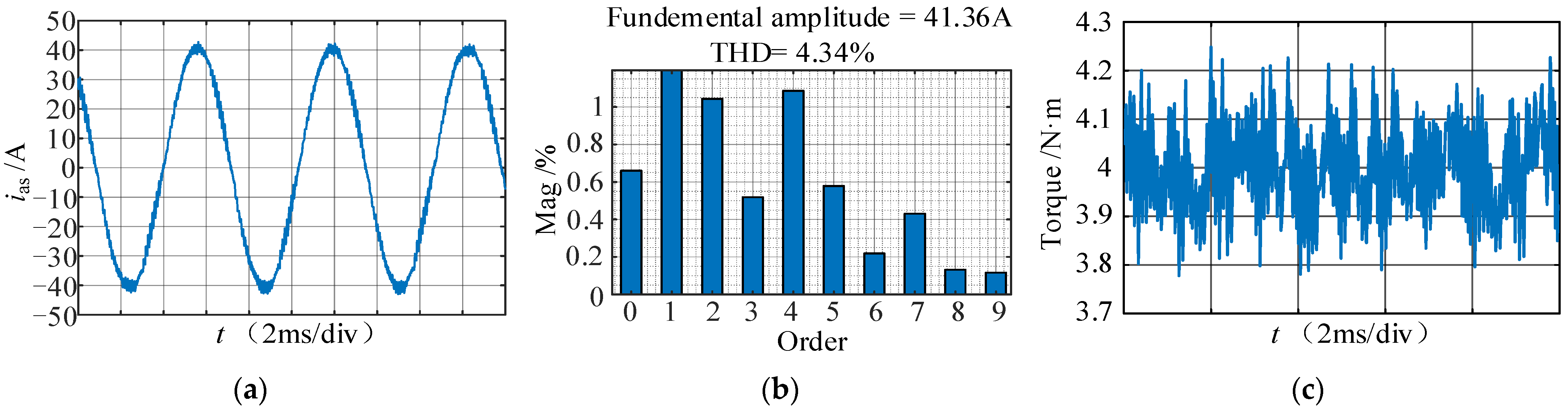
- Based on current loop stability and the harmonic suppression effect, according to the bode plot and the pole distribution diagram, the proposed 6th harmonic controller can effectively suppress the low-order harmonic distortion of the nonlinear voltage, without generating harmonic distortion of other frequencies, and does not affect the control performance of the current loop;
- (3)
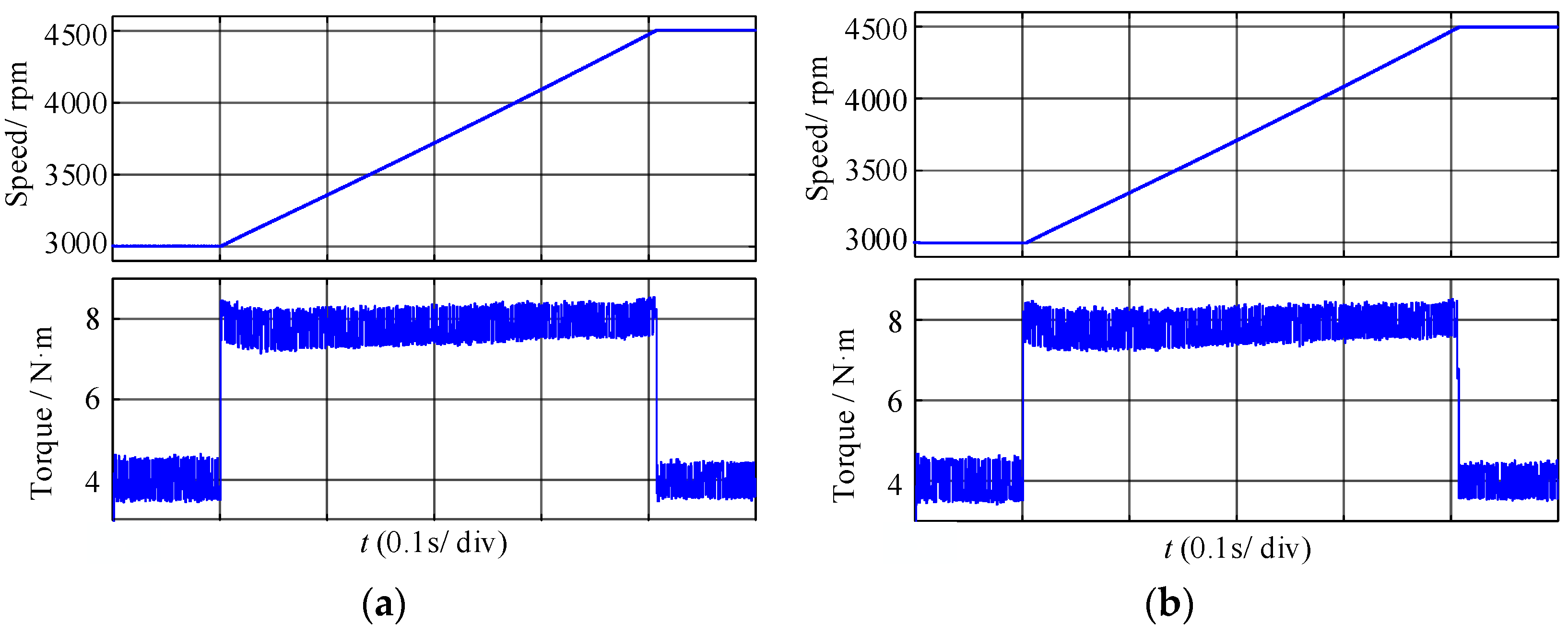
- Since another resonant controller for the low-speed range is introduced, low-order harmonic suppression at all operating frequencies can be achieved;
- (4)
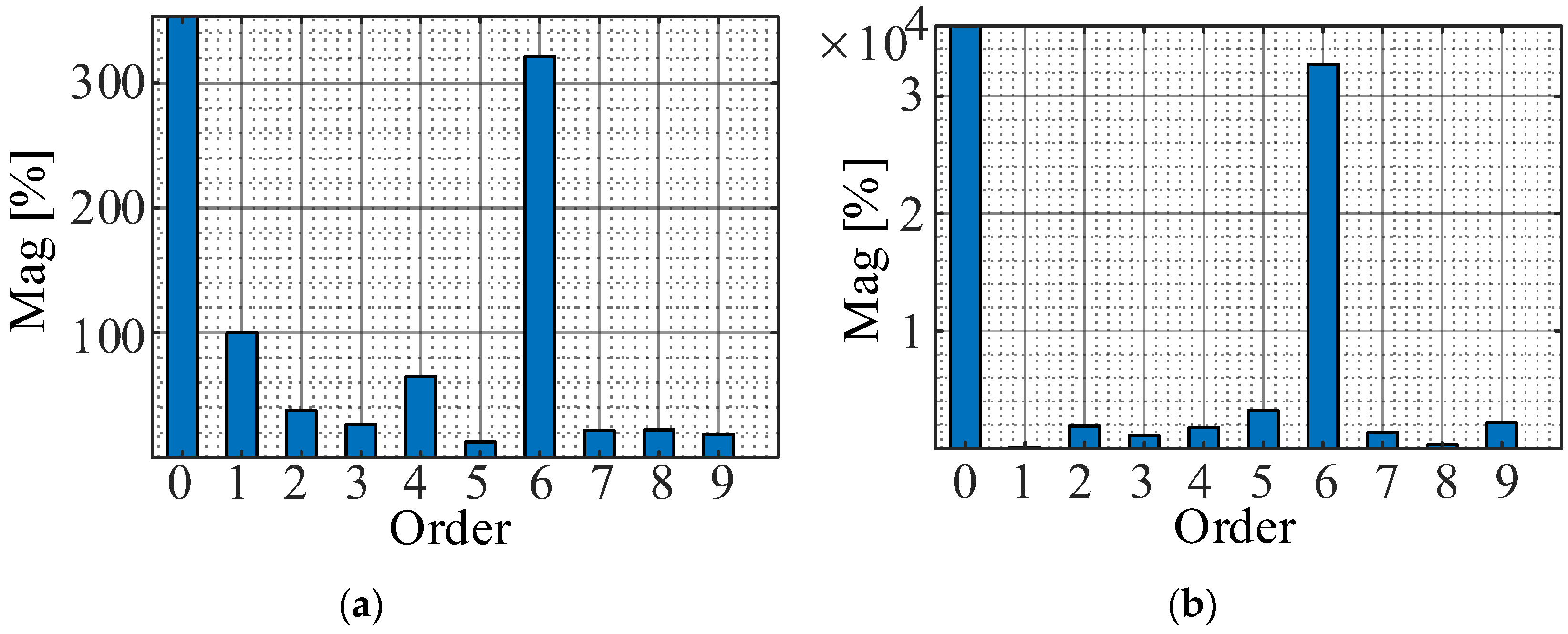
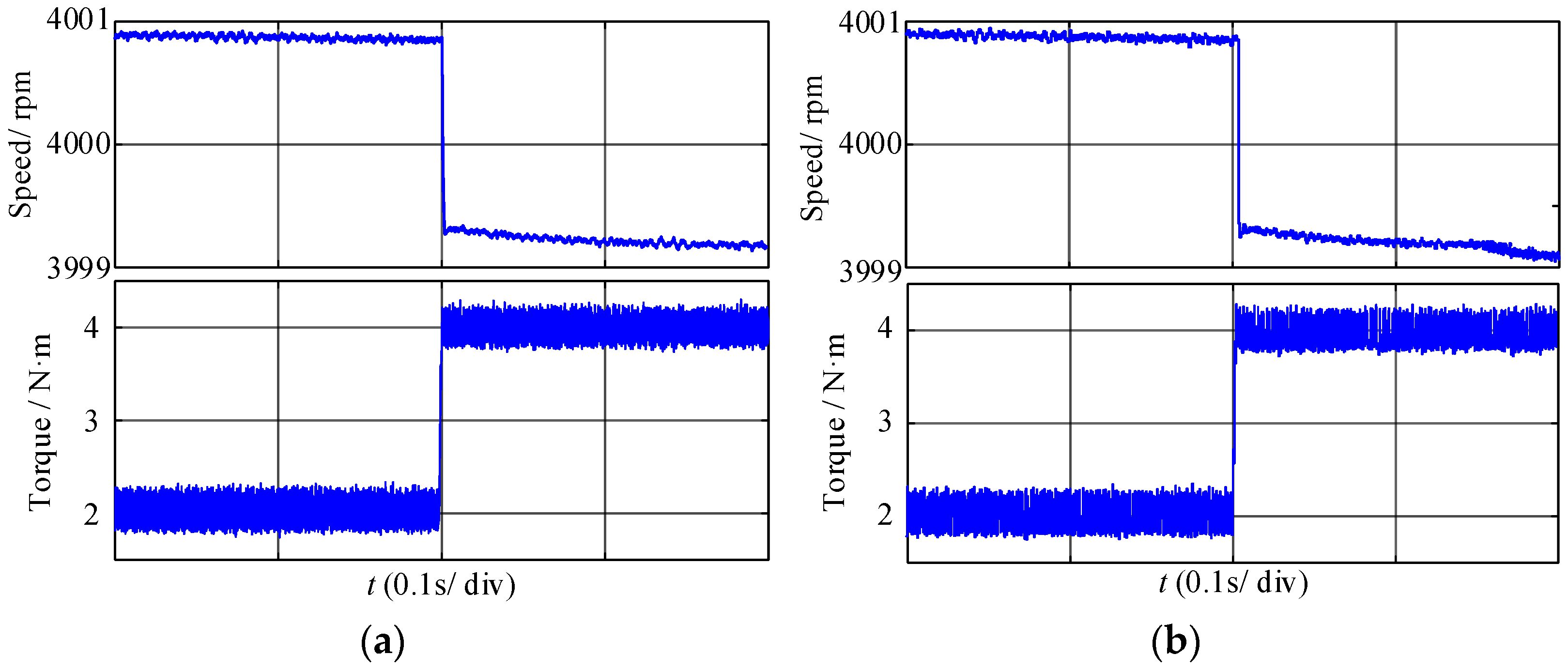
- Suppressing the 6th harmonic component of the stator current in d-q axis is an effective means to weaken the low-frequency resonance and vibration of the motor.
Author Contributions
Funding
Data Availability Statement
Conflicts of Interest
References
- Du, G.; Zou, Y.; Zhang, X.; Guo, L.; Guo, N. Heuristic Energy Management Strategy of Hybrid Electric Vehicle Based on Deep Reinforcement Learning with Accelerated Gradient Optimization. IEEE Trans. Transp. Electrif. 2021, 7, 2194–2208. [Google Scholar] [CrossRef]
- Liang, J.; Howey, B.; Bilgin, B.; Emadi, A. Source of Acoustic Noise in a 12/16 External-Rotor Switched Reluctance Motor: Stator Tangential Vibration and Rotor Radial Vibration. IEEE Open J. Ind. Appl. 2020, 1, 63–73. [Google Scholar] [CrossRef]
- Miao, Y.; Liu, H.; Zhang, W.; Liu, P. Optimal Control Strategy of Storage Inductor Current and Rotor Flux for Current Source Inverter Motor Drive System. Proc. CSEE 2019, 39, 2757–2767. [Google Scholar]
- Song, P.; Liu, Y.; Liu, C. Research on Parameter Design and Control Method for Current Source Inverter–Fed IM Drive Systems. Machines 2022, 10, 922. [Google Scholar] [CrossRef]
- Jiang, Z.; Ying, D.; Jian, S. Electromagnetic Noise Characteristics of Permanent Magnet Synchronous Motor Applied in Electric Vehicle. Trans. China Electrotech. Soc. 2016, 31, 53–59. [Google Scholar]
- Dong, Z.; Liu, C.; Song, Z.; Liu, S. Suppression of Dual−Harmonic Components for Five−Phase Series−Winding PMSM. IEEE Trans. Transp. Electrif. 2022, 8, 121–134. [Google Scholar] [CrossRef]
- Lai, Y.-S.; Chang, Y.-T.; Chen, B.-Y. Novel Random-Switching PWM Technique with Constant Sampling Frequency and Constant Inductor Average Current for Digitally Controlled Converter. IEEE Trans. Ind. Electron. 2013, 60, 3126–3135. [Google Scholar] [CrossRef]
- Peng, H.; Heping, L.; Yiru, M.; You, X.; Guo, Q. Variable Switching Frequency Pulse Width Modulation for Induction Motors based on Current Ripple Peak Value. Trans. China Electrotech. Soc. 2020, 35, 4373–4383. [Google Scholar]
- Liu, P.; Xu, J.; Sun, M.; Yuan, J.; Blaabjerg, F. New Discontinuous Space Vector Modulation Strategies for Impedance-Source Inverter with Superior Thermal and Harmonic Performance. IEEE Trans. Ind. Electron. 2022, 69, 13079–13089. [Google Scholar] [CrossRef]
- Guo, Q.; Dong, Z.; Liu, H.; You, X. Nonlinear Characteristics Compensation of Inverter for Low-Voltage Delta-Connected Induction Motor. Energies 2020, 13, 590. [Google Scholar] [CrossRef] [Green Version]
- Liu, P.; Xu, J.; Yang, Y.; Wang, H.; Blaabjerg, F. Impact of Modulation Strategies on the Reliability and Harmonics of Impedance-Source Inverters. IEEE J. Emerg. Sel. Top. Power Electron. 2020, 8, 3968–3981. [Google Scholar] [CrossRef]
- Zhang, Z.; Xu, L. Dead-Time Compensation of Inverters Considering Snubber and Parasitic Capacitance. IEEE Trans. Power Electron. 2014, 29, 3179–3187. [Google Scholar] [CrossRef]
- Liu, H.; Liu, Q.; Zhang, W.; Miao, Y.; Liu, P. Random PWM Technique for Acoustic Noise and Vibration Reduction in Induction Motors used by Electric Vehicles. Trans. China Electrotech. Soc. 2019, 34, 1488–1495. [Google Scholar]
- Kobayashi, T.; Tajima, F.; Ito, M.; Shibukawa, S. Effects of Slot Combination on Acoustic Noise from Induction Motors. IEEE Trans. Magn. 1997, 33, 2101–2104. [Google Scholar] [CrossRef]
- Gao, X.; Su, D. Suppression of a Certain Vehicle Electrical Field and Magnetic Field Radiation Resonance Point. IEEE Trans. Veh. Technol. 2018, 67, 226–234. [Google Scholar] [CrossRef]
- Wu, Z.; Ding, K.; Yang, Z.; He, G. Analytical Prediction and Minimization of Deadtime-Related Harmonics in Permanent Magnet Synchronous Motor. IEEE Trans. Ind. Electron. 2021, 68, 7736–7746. [Google Scholar] [CrossRef]
- Liu, H.; Lu, Y.; Wang, H.; Miao, Y. Dead-time Compensation Modulation Strategy of Subsection Integrated in Voltage Source Inverter. Electr. Mach. Control 2018, 22, 25–32. [Google Scholar]
- Miao, Y.; Liu, H.; Wang, H.; Lu, Y. Average Current Feedforward Compensation Strategy of Overlap-Time Effect for Current Source Inverter. Proc. CSEE 2018, 38, 4183–4193. [Google Scholar]
- Liao, Y.; Zhen, S.; Liu, R.; Yao, J. Torque Ripple Suppression of Permanent Magnet Synchronous Motor by the Harmonic Injection. Proc. CSEE 2011, 21, 119–127. [Google Scholar]
- Yang, Y.; Zhou, K.; Wang, H.; Blaabjerg, F.; Wang, D.; Zhang, B. Frequency Adaptive Selective Harmonic Control for Grid-Connected Inverters. IEEE Trans. Power Electron. 2015, 30, 3912–3924. [Google Scholar] [CrossRef]
- da Silveira, D.B.; Farias, J.V.M.; Pereira, H.A.; Luiz, A.-S.A.; Stopa, M.M.; Cupertino, A.F. Mitigation of torque oscillations caused by dc injection-based resistance estimation through resonant controllers. In Proceedings of the 2021 Brazilian Power Electronics Conference (COBEP), João Pessoa, Brazil, 7–10 November 2021; pp. 1–6. [Google Scholar]


| Parameters | Value | Parameters | Value |
|---|---|---|---|
| Rated voltage | 48 V | Rotor outer diameter | 109 mm |
| Rated power | 10 kW | Rotor inner diameter | 36 mm |
| Maximum speed | 6000 rpm | Rotor slot number | 42 |
| Pole pairs | 2 | Iron core length | 180 mm |
| stator Outer diameter | 188 mm | Stator resistance | 0.047 Ω |
| Stator inner diameter | 110 mm | Stator leakage inductance | 81.5 µF |
| stator slot number | 36 | Rotor resistance | 0.028 Ω |
| Rotor leakage inductance | 81.3 µF | Excitation inductance | 2.29 mH |
| Parameters | Value | Parameters | Value |
|---|---|---|---|
| Switching cycle | 10 kHz | Simulation step size | 0.5 μs |
| Sampling cycle | 10 kHz | Voltage drop of the switching devices | 0.5 V |
| Deadtime | 2 μs | Voltage drop of the diode | 0.7 V |
| Compensation Method | THD | 5th Harmonic | 7th Harmonic | Torque Ripple (N·m) |
|---|---|---|---|---|
| No compensation | 5.88% | 2.9% | 1.4% | 3.6 to 4.3 |
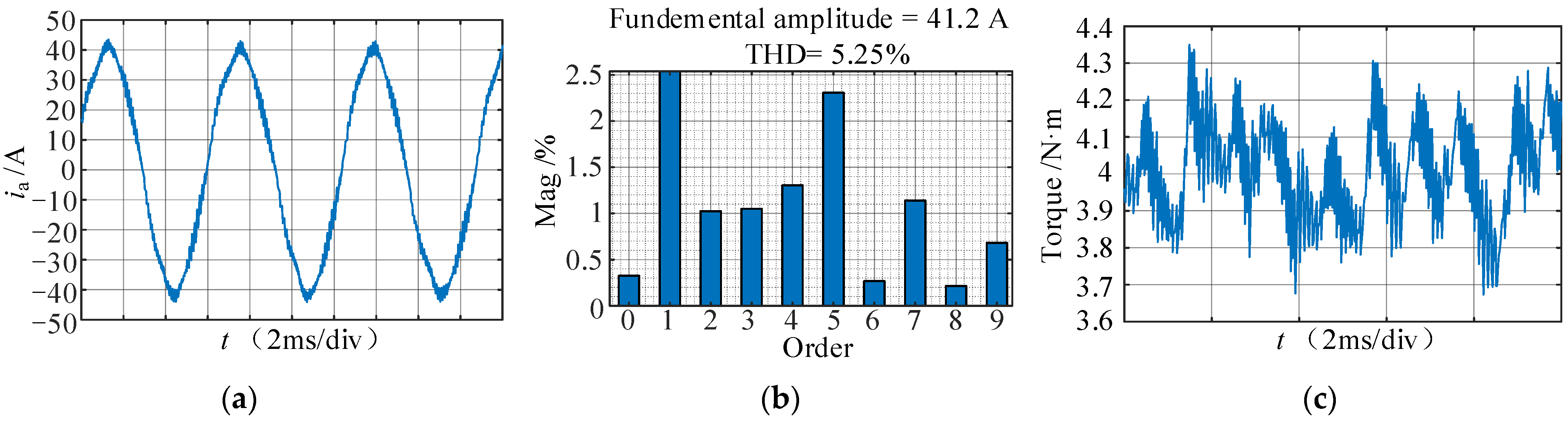
| Pulse time compensation | 5.33% | 2.3% | 1.2% | 3.7 to 4.3 |
| 6th harmonic controller | 4.34% | 0.58% | 0.43% | 3.8 to 4.2 |
Publisher’s Note: MDPI stays neutral with regard to jurisdictional claims in published maps and institutional affiliations. |
© 2022 by the authors. Licensee MDPI, Basel, Switzerland. This article is an open access article distributed under the terms and conditions of the Creative Commons Attribution (CC BY) license (https://creativecommons.org/licenses/by/4.0/).
Share and Cite
Song, P.; Liu, Y.; Liu, T.; Wang, H.; Wang, L. A Novel Suppression Method for Low-Order Harmonics Causing Resonance of Induction Motor. Machines 2022, 10, 1206. https://doi.org/10.3390/machines10121206
Song P, Liu Y, Liu T, Wang H, Wang L. A Novel Suppression Method for Low-Order Harmonics Causing Resonance of Induction Motor. Machines. 2022; 10(12):1206. https://doi.org/10.3390/machines10121206
Chicago/Turabian StyleSong, Pengyun, Yanghui Liu, Tao Liu, Huazhang Wang, and Liwei Wang. 2022. "A Novel Suppression Method for Low-Order Harmonics Causing Resonance of Induction Motor" Machines 10, no. 12: 1206. https://doi.org/10.3390/machines10121206