


Study of Diamond Wheel Wear Based on the Principle of Frictional Energy Distribution in Ultrasonic-Assisted Grinding Trajectories

Abstract
:1. Introduction
2. Processing Principle and Experimental Device
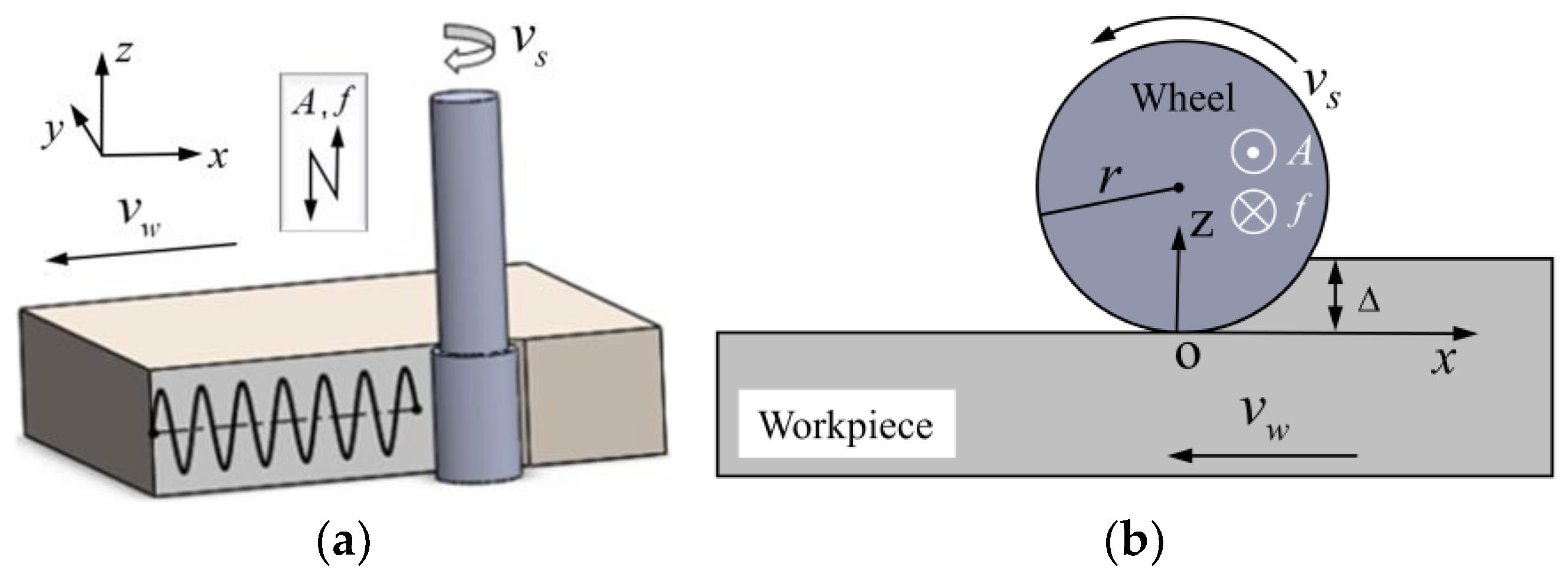
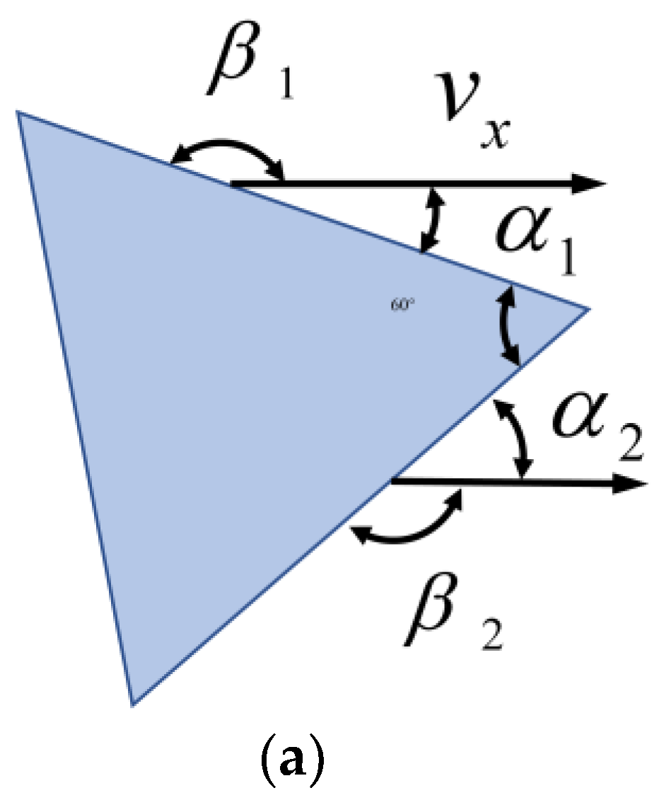
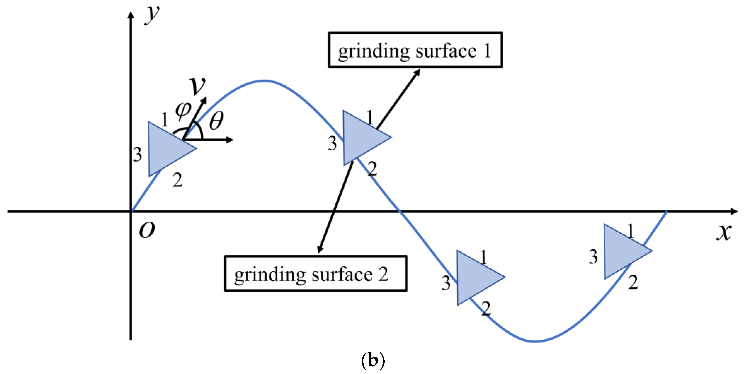
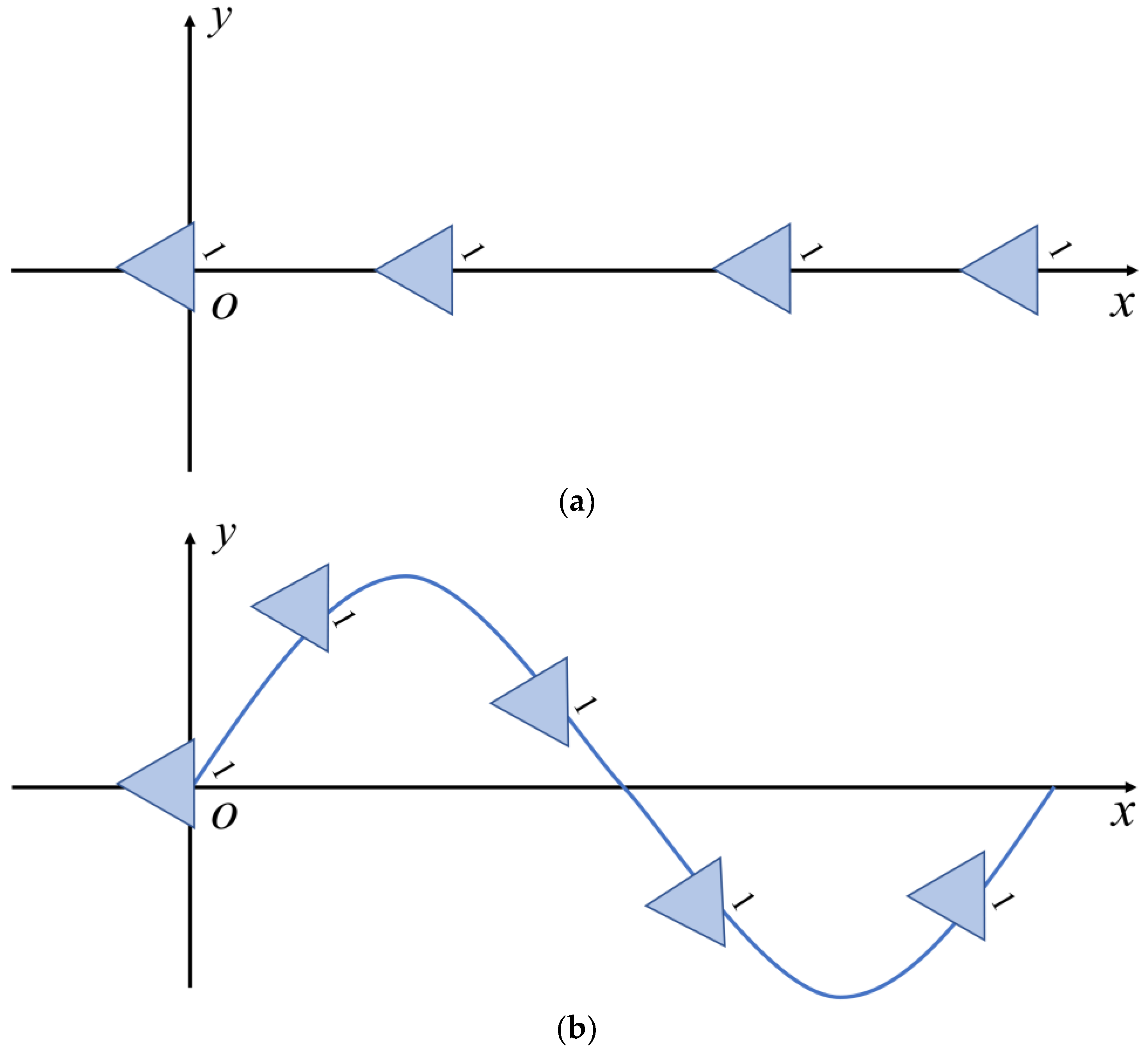
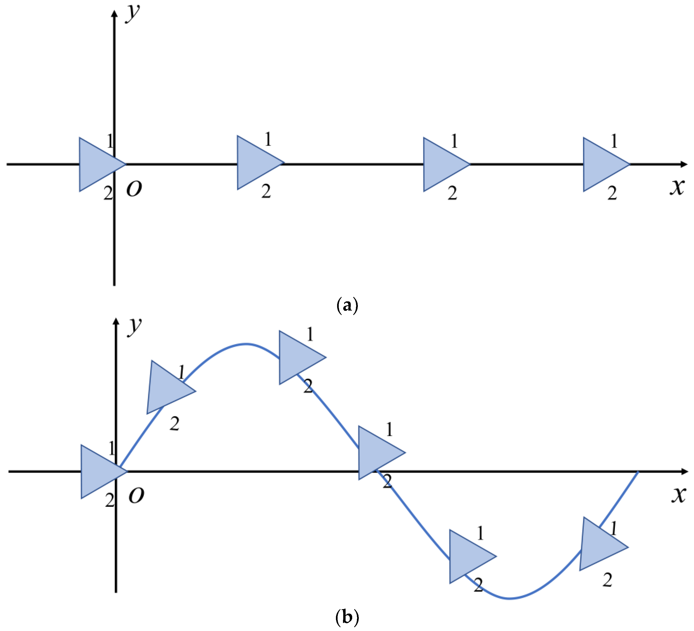
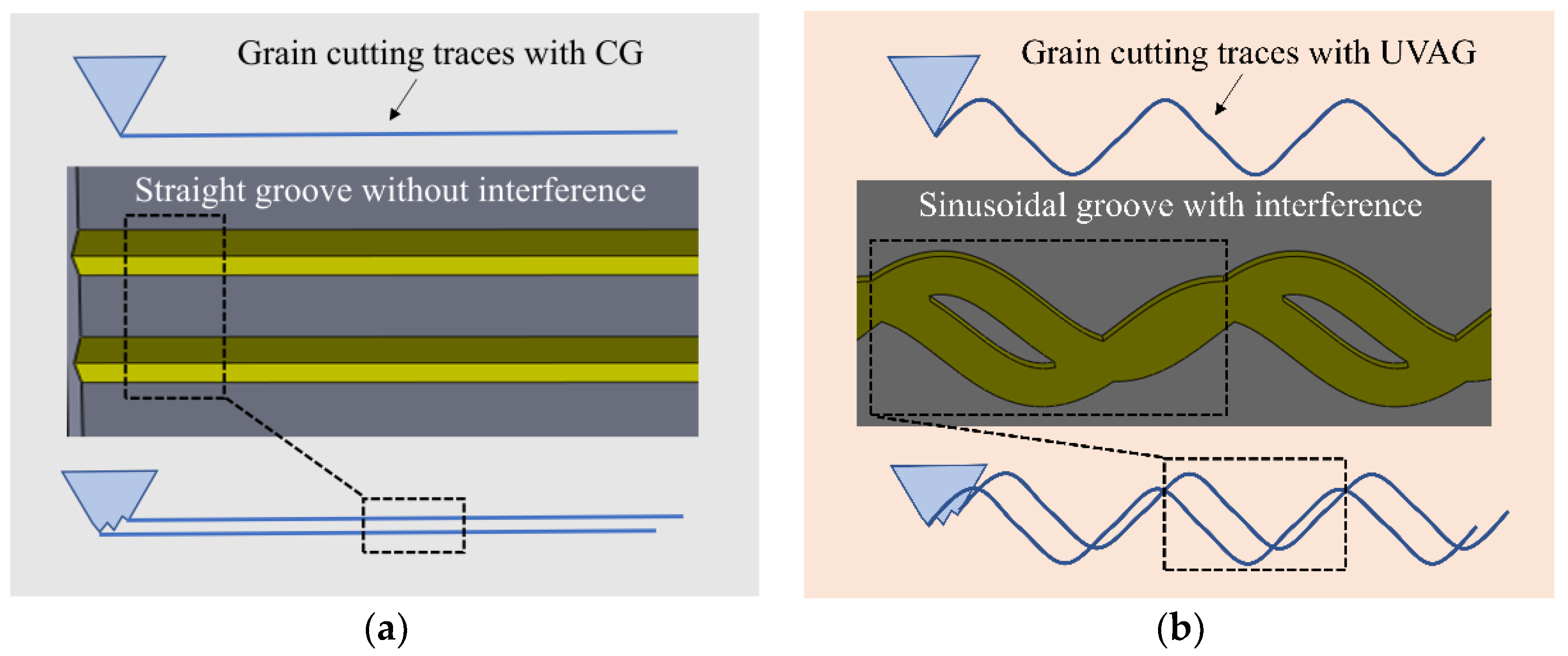
2.1. Processing Principle
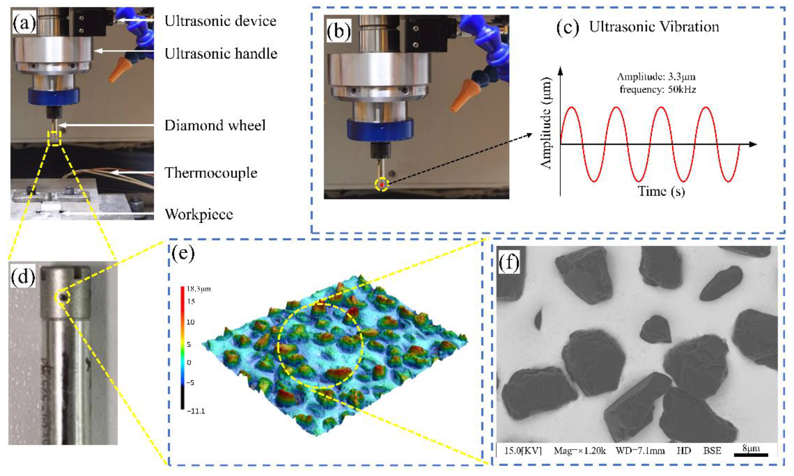
2.2. Experimental Setup
2.3. Experimental Conditions and Process
3. Experimental Results
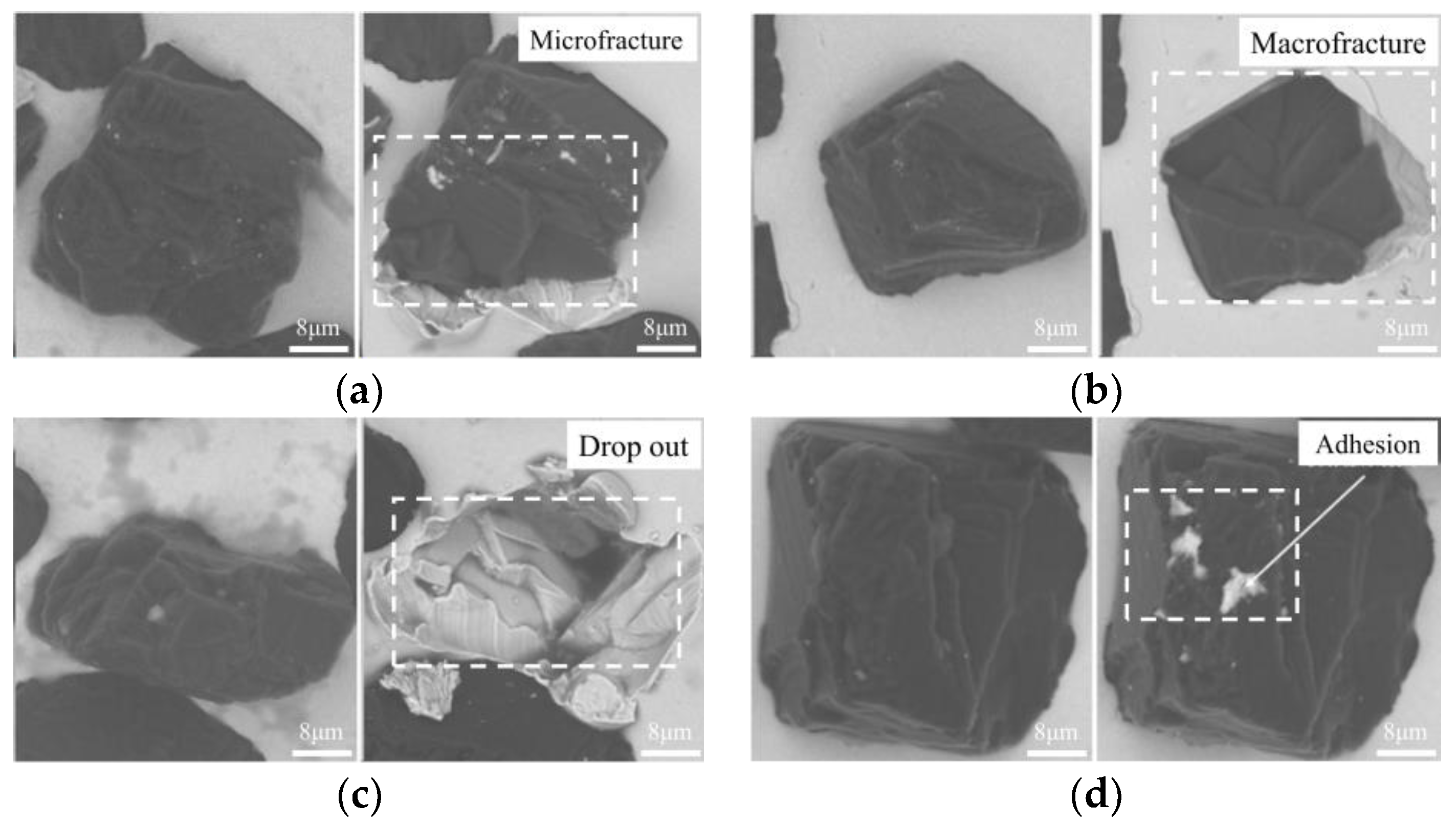
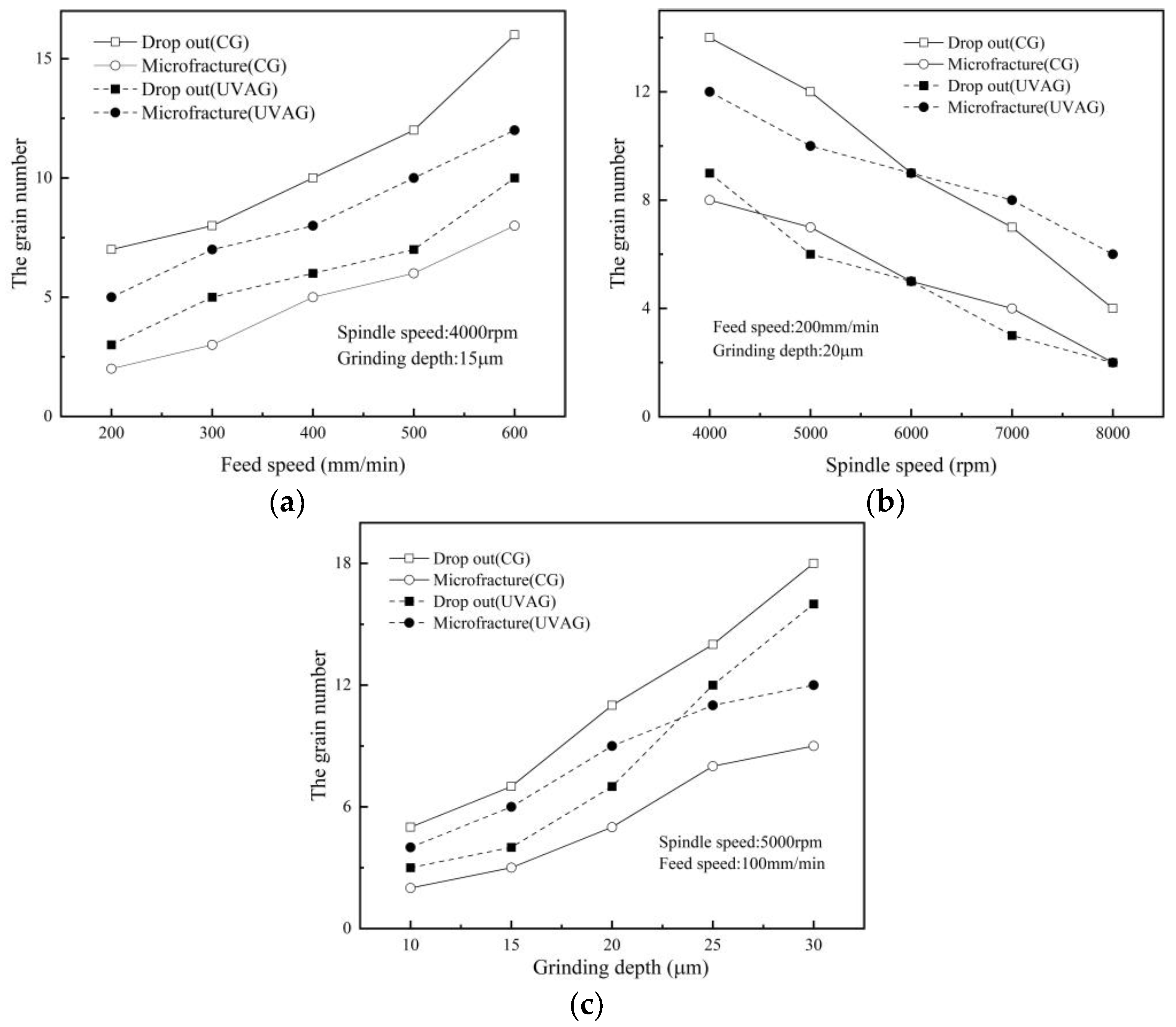
3.1. Grinding Wheel Wear
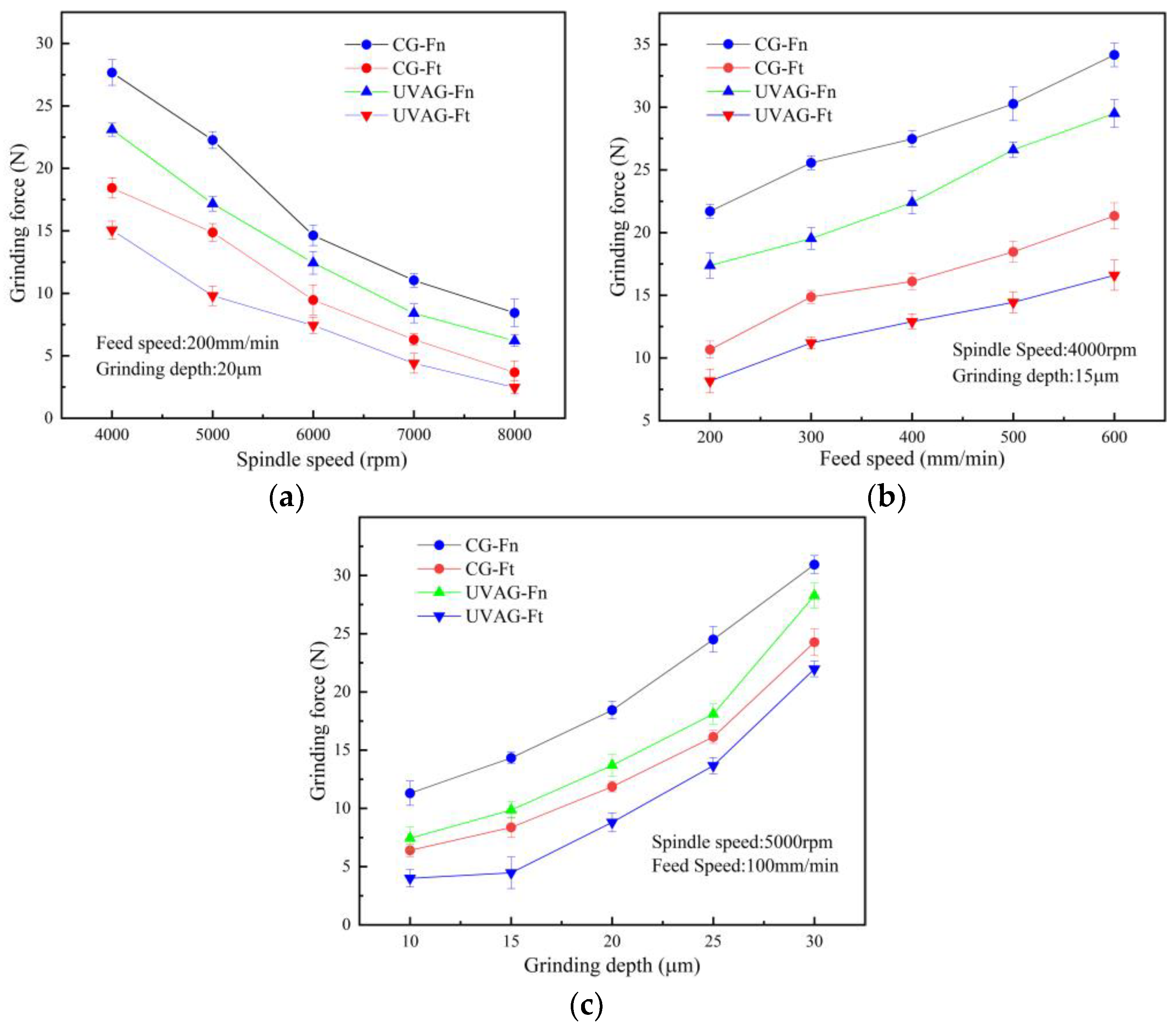
3.2. Grinding Forces
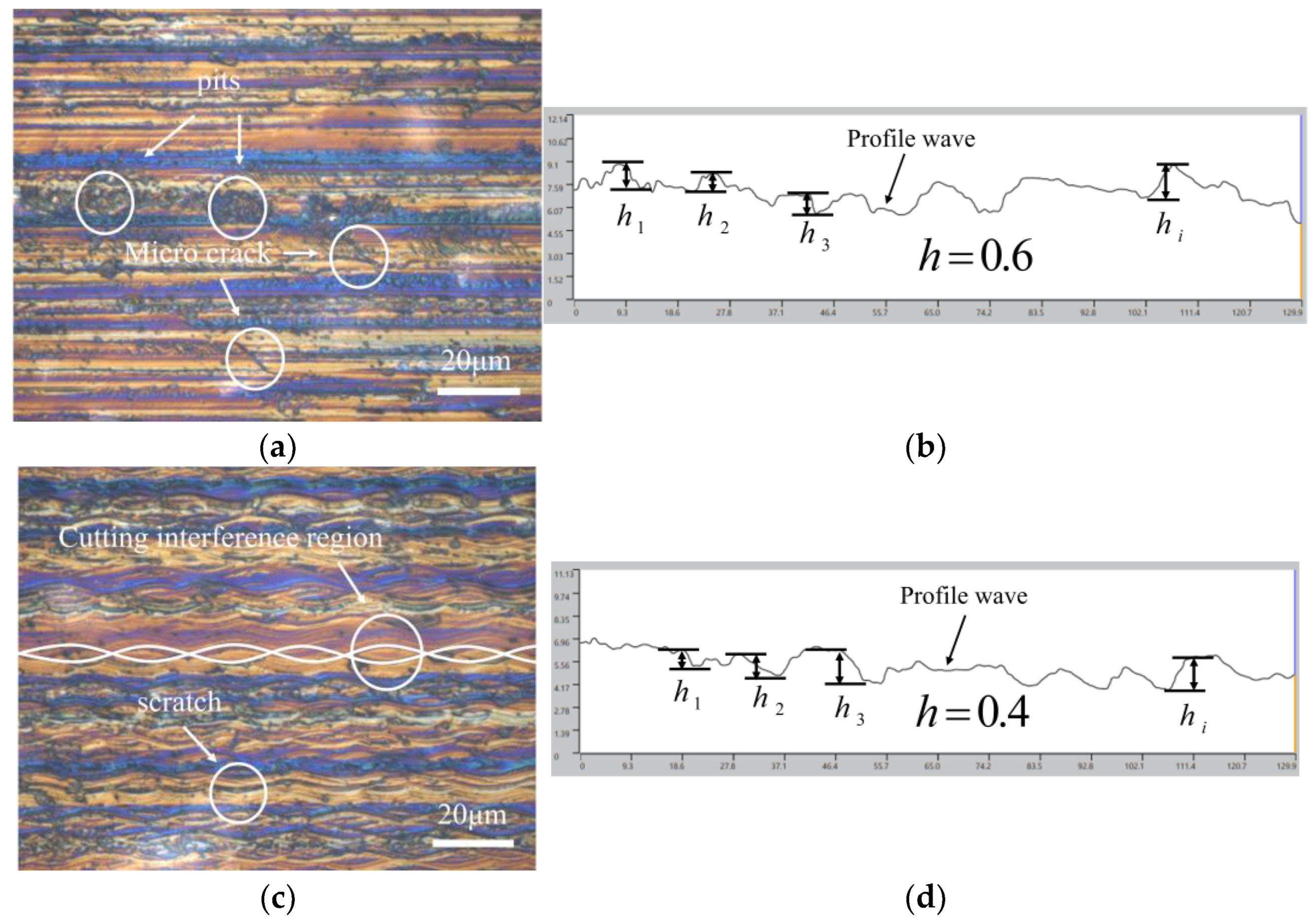
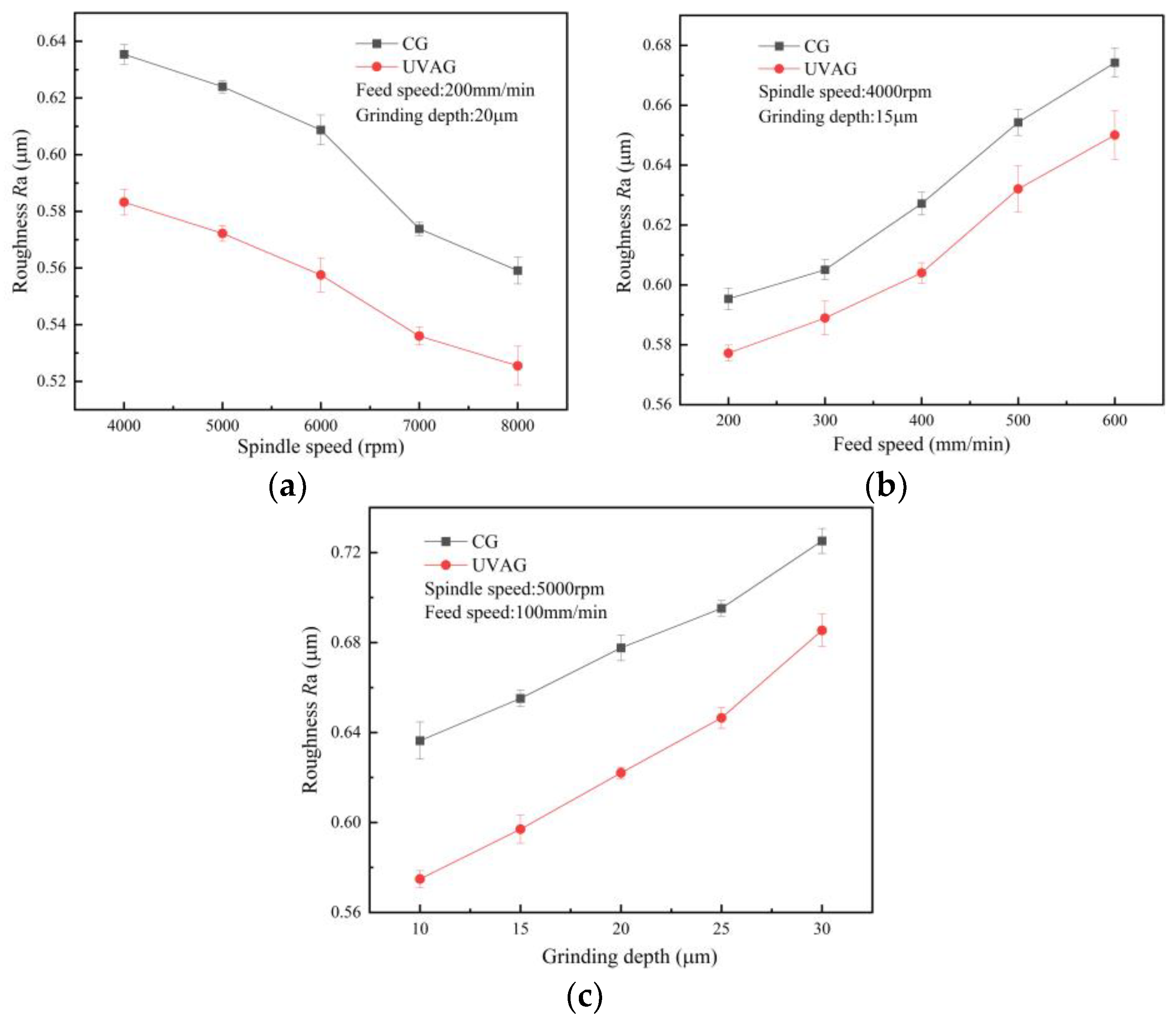
3.3. Surface Quality
4. Discussion
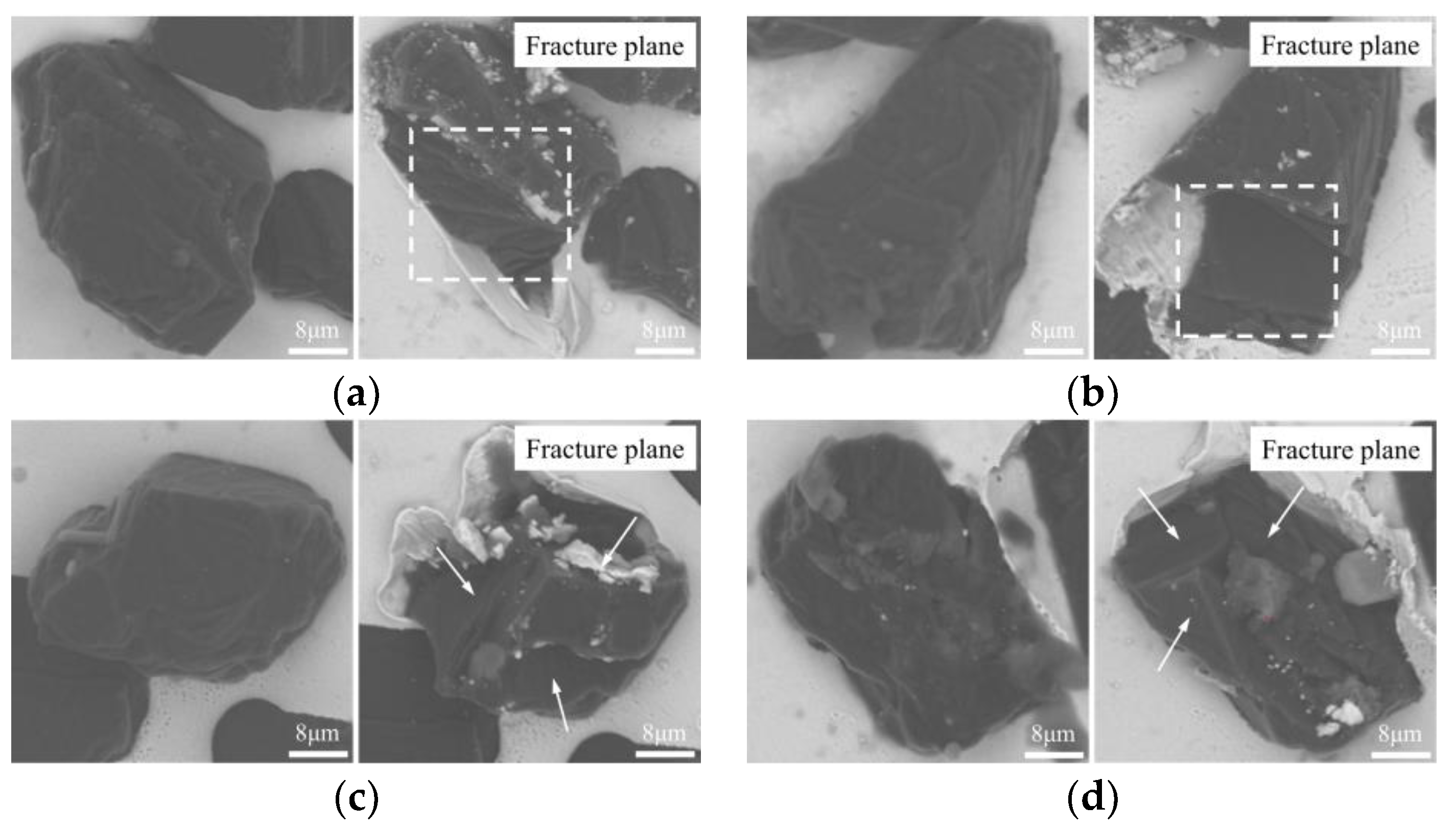
4.1. Grain Wear
4.2. Grinding Force
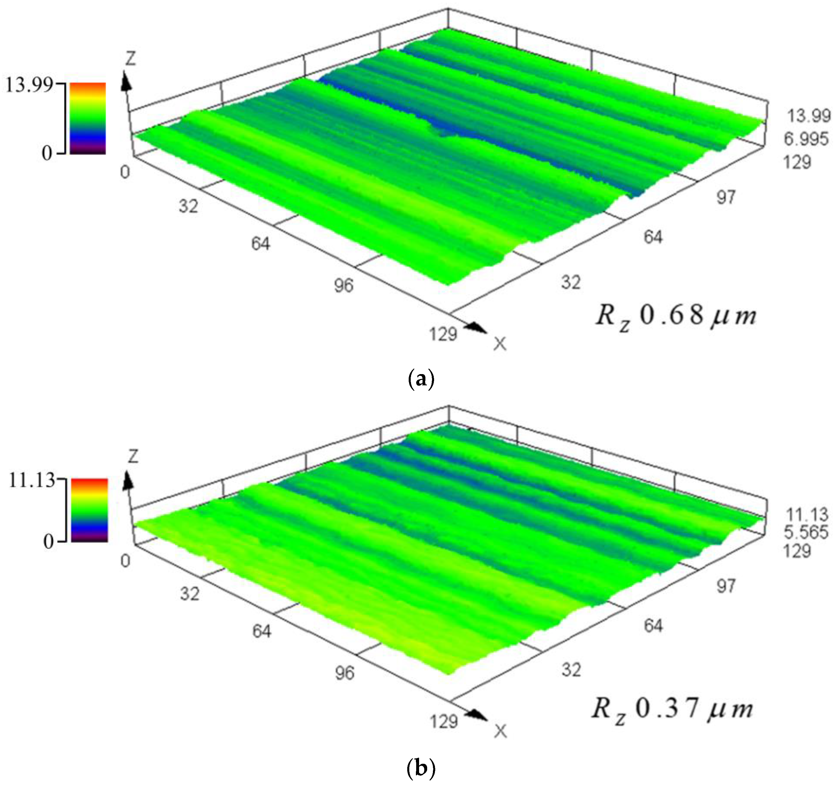
4.3. Surface Quality
5. Conclusions
- In UVAG, the grinding surface of the grain changes, and the generated friction energy is distributed. The friction energy of a single grinding surface is reduced, and microfracture easily occurs.
- When the angle of the grain plunge is 90° and 150°, compared with CG, the friction energy generated by the UVAG grain grinding surface is reduced by 24% and 37%.
- In UVAG, the microfracture of grains produces more effective cutting edges, which can obtain a better grinding surface quality. Compared with CG, Ra decreased by 12.3% and Rz decreased by 45.6%.
Author Contributions
Funding
Data Availability Statement
Conflicts of Interest
References
- Xiao, X.Z.; Zheng, K.; Liao, W.H.; Meng, H. Study on cutting force model in ultrasonic vibration assisted side grinding of zirconia ceramics. Int. J. Mach. Tools Manuf. 2016, 104, 58–67. [Google Scholar] [CrossRef]
- Manicone, P.F.; Iommetti, P.R.; Raffaelli, L. An overview of zirconia ceramics: Basic properties and clinical applications. J. Dent. 2007, 35, 819–826. [Google Scholar] [CrossRef]
- Soon, G.; Pingguan-Murphy, B.; Lai, K.W.; Akbar, S.A. Review of zirconia-based bioceramic: Surface modification and cellular response. Ceram. Int. 2016, 42, 12543–12555. [Google Scholar] [CrossRef]
- Zhang, Y.; Lawn, B.R. Novel Zirconia Materials in Dentistry. J. Dent. Res. Off. Publ. Int. Assoc. Dent. Res. 2018, 97, 140–147. [Google Scholar] [CrossRef] [PubMed]
- Zhang, X.H.; Kang, Z.X.; Li, S.; Shi, Z.Y.; Wen, D.D.; Jiang, J.; Zhang, Z.C. Grinding force modelling for ductile-brittle transition in laser macro-micro-structured grinding of zirconia ceramics. Ceram. Int. 2019, 45, 18487–18500. [Google Scholar] [CrossRef]
- Ji, B.; Alrayes, A.A.; Zhao, J.; Feng, Y.Z.; Shen, Z.J. Grinding and polishing efficiency of a novel self-glazed zirconia versus the conventional dry-pressed and sintered zirconia ceramics. Adv. Appl. Ceram. 2018, 118, 46–55. [Google Scholar] [CrossRef]
- Dai, S.; Lei, H.; Fu, J.F. Self-assembly preparation of popcorn-like colloidal silica and its application on chemical mechanical polishing of zirconia ceramic. Ceram. Int. 2020, 46, 24225–24230. [Google Scholar] [CrossRef]
- Zhang, X.H.; Wang, Z.R.; Shi, Z.Y.; Shi, Z.J.; Jiang, R.Y.; Kang, Z.X. Improved grinding performance of zirconia ceramic using an innovative biomimetic fractal-branched grinding wheel inspired by leaf vein—ScienceDirect. Ceram. Int. 2020, 46, 22954–22963. [Google Scholar] [CrossRef]
- Zhang, M.H.; Pang, Z.X.; Jia, Y.X.; Shan, C.W. Understanding the machining characteristic of plain weave ceramic matrix composite in ultrasonic-assisted grinding. Ceram. Int. 2022, 48, 5557–5573. [Google Scholar] [CrossRef]
- Kwon, W.; Kim, T.; Song, K.Y. Experimental Investigation on CO2 Laser-Assisted Micro-Grinding Characteristics of Al2O3. Int. J. Precis. Eng. Manuf. 2021, 22, 51–62. [Google Scholar] [CrossRef]
- Rao, X.S.; Zhang, F.H.; Li, C.; Li, Y.J. Experimental investigation on electrical discharge diamond grinding of RB-SiC ceramics. Int. J. Adv. Manuf. Technol. 2018, 94, 2751–2762. [Google Scholar] [CrossRef]
- Zhao, B.; Chang, B.Q.; Wang, X.B.; Bie, W.B. System design and experimental research on ultrasonic assisted elliptical vibration grinding of Nano-ZrO2 ceramics. Ceram. Int. 2019, 45, 24865–24877. [Google Scholar] [CrossRef]
- Kadivar, M.; Shamray, S.; Soltani, B.; Daneshi, A.; Azarhoushang, B. Laser-assisted micro-grinding of Si3N4. Precis. Eng. 2019, 60, 394–404. [Google Scholar] [CrossRef]
- Ma, Z.L.; Wang, Q.H.; Dong, J.D.; Wang, Z.; Yu, T.B. Experimental investigation and numerical analysis for machinability of alumina ceramic by laser-assisted grinding. Precis. Eng. 2021, 72, 798–806. [Google Scholar] [CrossRef]
- Kumar, M.; Satsangi, P.S. A study on machining performance of wire electric discharge grinding (WEDG) process during machining of tungsten alloy micro-tools. Sadhana 2021, 46, 1–11. [Google Scholar] [CrossRef]
- Rao, X.S.; Zhang, F.H.; Lu, Y.J.; Luo, X.C.; Chen, F.M. Surface and subsurface damage of reaction-bonded silicon carbide induced by electrical discharge diamond grinding. Int. J. Mach. Tools Manuf. 2020, 154, 103564. [Google Scholar] [CrossRef]
- Zhang, Q.J.; Li, J.Y.; Cai, Y.L.; Wang, H. Study on Electrical Discharge and Ultrasonic Assisted Mechanical Combined Machining of Polycrystalline Diamond. Procedia CIRP 2013, 6, 589–593. [Google Scholar]
- Das, S.; Pandivelan, C. Grinding characteristics during ultrasonic vibration assisted grinding of alumina ceramic in selected dry and MQL conditions. Mater. Res. Express 2020, 7, 85404. [Google Scholar] [CrossRef]
- Ding, K.; Fu, Y.C.; Su, H.H.; Gong, X.B.; Wu, K.Q. Wear of diamond grinding wheel in ultrasonic vibration-assisted grinding of silicon carbide. Int. J. Adv. Manuf. Technol. 2014, 71, 1929–1938. [Google Scholar] [CrossRef]
- Shen, J.Y.; Wang, J.Q.; Jiang, B.; Xu, X.P. Study on wear of diamond wheel in ultrasonic vibration-assisted grinding ceramic. Wear 2015, 332–333, 788–793. [Google Scholar] [CrossRef]
- Baraheni, M.; Amini, S. Mathematical model to predict cutting force in rotary ultrasonic assisted end grinding of Si3N4 considering both ductile and brittle deformation. Meas. J. Int. Meas. Confed. 2020, 156, 107586. [Google Scholar] [CrossRef]
- Lei, X.F.; Xiang, D.H.; Peng, P.C.; Liu, G.F.; Li, B.; Zhao, B.; Gao, G.F. Establishment of dynamic grinding force model for ultrasonic-assisted single abrasive high-speed grinding. J. Mater. Process. Technol. 2022, 300, 117420. [Google Scholar] [CrossRef]
- Liang, Z.Q.; Wang, X.B.; Wu, Y.B.; Xie, L.J.; Liu, Z.B.; Zhao, W.X. An investigation on wear mechanism of resin-bonded diamond wheel in Elliptical Ultrasonic Assisted Grinding (EUAG) of monocrystal sapphire. J. Mater. Process. Technol. 2012, 212, 868–876. [Google Scholar] [CrossRef]
- Ding, K.; Fu, Y.C.; Su, H.H.; Xu, H.X.; Cui, F.F.; Li, Q.L. Experimental studies on matching performance of grinding and vibration parameters in ultrasonic assisted grinding of SiC ceramics. Int. J. Adv. Manuf. Technol. 2017, 88, 2527–2535. [Google Scholar] [CrossRef]
- Zheng, K.; Li, Z.H.; Liao, W.H.; Xiao, X.Z. Friction and wear performance on ultrasonic vibration assisted grinding dental zirconia ceramics against natural tooth. J. Braz. Soc. Mech. Sci. Eng. 2017, 39, 833–843. [Google Scholar] [CrossRef]
- Zou, L.; Huang, Y.; Zhou, M.; Duan, L. Investigation on diamond tool wear in ultrasonic vibration-assisted turning die steels. Mater. Manuf. Process. 2006, 32, 1505–1511. [Google Scholar] [CrossRef]
- Tsai, C.; Tseng, C. The effect of friction reduction in the presence of in-plane vibrations. Arch. Appl. Mech. 2006, 75, 164–176. [Google Scholar] [CrossRef]
- Wu, B.F.; Zhao, B.; Ding, W.F.; Su, H.H. Investigation of the wear characteristics of microcrystal alumina abrasive wheels during the ultrasonic vibration-assisted grinding of PTMCs. Wear 2021, 477, 203844. [Google Scholar] [CrossRef]
- Agarwal, S.; Venkateswara, R.P. Predictive modeling of undeformed chip thickness in ceramic grinding. Int. J. Mach. Tools Manuf. 2012, 56, 59–68. [Google Scholar] [CrossRef]
- Yang, Z.C.; Zhu, L.D.; Lin, B.; Zhang, G.X.; Ni, C.B.; Sui, T.Y. The grinding force modeling and experimental study of ZrO2 ceramic materials in ultrasonic vibration assisted grinding. Ceram. Int. 2019, 45, 8873–8889. [Google Scholar] [CrossRef]
- Ren, J.X.; Huang, D.A. Grinding Principle, 1st ed.; Publishing House of Electronics Industry: Beijing, China, 2011; pp. 41–61. [Google Scholar]


| Contents | Values |
|---|---|
| Grinding type | Flat surface grinding |
| Abrasive wheel | Diamond wheel (6D*6A*R0.5*38 L) |
| Ultrasonic frequency f | 50 kHz |
| Ultrasonic amplitude A | 3.3 μm |
| Grinding speed vs | 4000, 5000, 6000, 7000, 8000 (rpm) |
| Workpiece speed vw | 100, 200, 300, 400, 500, 600 (mm/min) |
| Depth of cut ∆ | 10, 15, 20, 25, 30 (μm) |
Publisher’s Note: MDPI stays neutral with regard to jurisdictional claims in published maps and institutional affiliations. |
© 2022 by the authors. Licensee MDPI, Basel, Switzerland. This article is an open access article distributed under the terms and conditions of the Creative Commons Attribution (CC BY) license (https://creativecommons.org/licenses/by/4.0/).
Share and Cite
Zhao, L.; Li, S.; Zhang, X.; Zhou, H.; Wang, Q. Study of Diamond Wheel Wear Based on the Principle of Frictional Energy Distribution in Ultrasonic-Assisted Grinding Trajectories. Machines 2022, 10, 1191. https://doi.org/10.3390/machines10121191
Zhao L, Li S, Zhang X, Zhou H, Wang Q. Study of Diamond Wheel Wear Based on the Principle of Frictional Energy Distribution in Ultrasonic-Assisted Grinding Trajectories. Machines. 2022; 10(12):1191. https://doi.org/10.3390/machines10121191
Chicago/Turabian StyleZhao, Longfei, Sisi Li, Xianglei Zhang, Hongming Zhou, and Qiang Wang. 2022. "Study of Diamond Wheel Wear Based on the Principle of Frictional Energy Distribution in Ultrasonic-Assisted Grinding Trajectories" Machines 10, no. 12: 1191. https://doi.org/10.3390/machines10121191