Article

Developing and Testing the Proto Type Structure for Micro Tool Fabrication

1
College of Mechanical and Electrical Engineering, Changsha University, Changsha 410022, China
2
Hunan TGONG Precision Technology Co., Ltd., Changsha 410000, China
3
College of Intelligent Science and Technology, National University of Defense Technology, Changsha 410073, China
4
College of Mechanical and Vehicle Engineering, Hunan University, Changsha 410082, China
*
Author to whom correspondence should be addressed.
Machines 2022, 10(10), 938; https://doi.org/10.3390/machines10100938
Submission received: 21 August 2022 / Revised: 2 October 2022 / Accepted: 8 October 2022 / Published: 16 October 2022
(This article belongs to the Special Issue High Precision Abrasive Machining: Machines, Processes and Systems)

Abstract

:
Compared with traditional machine tools, the micro machine tools have advantages of small volume, low cost, less energy consumption, high efficiency and high flexibility. Therefore, it is regarded as an important equipment for micro-cutting machining which has been used widely all over the world and. As a key component of the micro-cutting machine tools, the body structure directly influences the machining performance. Thus, an integral column and base structure for micro machining tools was proposed in this work, and the detailed structural parameters were designed based on parameter analysis. Besides, the static and dynamic performance of the proposed machine were analyzed and compared between the integral structure and the separated one. The deformation and stress of the proposed structures under typical working conditions were studied by numerical simulation, along with the natural frequencies, vibration modes and frequency response peaks. Further, optimization was performed on the integral body structure, the prototype of the micro-machine tool was trial-produced, and the positioning accuracy of each coordinate axis was qualitatively analyzed. In addition, the micro-milling test was carried out with 6061 aluminum alloy to show the performance of the novel cutting machine. The results revealed that the proposed integrated micro-machine bed structure is superior to the separated structure in terms of static deformation and harmonic response characteristics, with good comprehensive mechanical properties, greatly improved static and dynamic performance of the machine tool, significantly improved structural accuracy, improved processing quality of the specimen and good application value.

1. Introduction

In recent years, due to the large demand in aerospace, microelectronics, and modern medicine [1], micro-miniature machinery has been widely used in the micro-sensorsin aerospace field, the microelectronic components in consumer field, and the microscopic surgical devices in medical field [2,3]. Nowadays, the micro-cutting is generally fabricated by traditional ultra-precision machining equipment, with large size, high energy consumption, low efficiency and high cost [4,5]. Since the lack of micro small cutting machine tools, many micro-mechanical parts can only be manufactured by the traditional cutting methods. Therefore, it is necessary to develop a novel micro-cutting technology and its miniaturized machine tools with low energy consumption, low cost, high precision and high efficiency [6,7], which has become a hot spot and frontier in the field of modern manufacturing. At present, the challenges faced in manufacturing technology and micro-machine equipment mainly locatein the wide range of materials, complex structures and high machining precision required for the tiny parts.
There have been a lot of researches conducting on the structure of the micro cutting machines. For example, in terms of high-speed and ultra-high-speed micro-machine tools, Li et al. [8] developed a micro-milling processing test platform, which has a maximum speed of the pneumatic spindle about 500,000 rpm. But the machinable size is very small, unable to fabricate large work-piece. A micro-machine tool table driven by a DC servo motor was adopted by Axinten et al. [9]. The working stroke is 25 mm, the maximum feed rate is 300 mm/s, the maximum acceleration is 10 m/s2, and the repeatability is ±0.1 µm. Moreover, Zhang et al. [10] used permanent magnet linear motor with gas static pressure guide to feed, with the feed stroke of 75 mm, and a sub-micron positioning accuracy was presented. A number of processing experiments have been carried out with the developed micro-machine prototypes by various countries. Some tiny parts of these works are shown in Figure 1 [11,12], including the machines produced by Japan, Korea and UK. For the material constructing milling machine, resin concrete and composite concrete are commonly used in structural parts such as the bed of precision machine tools due to their good vibration resistance, low thermal diffusivity and corrosion resistance [13]. Cho et al. [14] applied resin concrete in small desktop machine tools, of which the basic structural parts were made of stainless steel plates sandwiched with resin concrete. Simulation analysis and experimental results showed that this type of structural parts not only improves the rigidity and the damping of the machine tool, but also greatly reduces the mass of the whole machine. Moreover, Xiao et al. [15] developed two prototypes of high-speed precision micro-spindles and their micro-tools with a diameter of 3.175 mm. Since the micro-bearings are directly supported, the performance of the micro-spindle under load can be improved by the super-high rotational speed of the pneumatic pressure effect. Chang et al. [16] presents development of a hybrid machine which combines micro milling, micro grinding, micro turning with laser machining capacities for the fabrication of 3D micro products and components.
In order to develop micro-machine tools for micro-cutting, this paper deeply studies the design and calculation of servo driven transmission technology of micro-machine tools, and establish the selection process and design calculation method of ball screw unit, linear guide unit and servo drive unit. The static and dynamic performances of the micro-machine tool are analyzed. Finally, a high-performance micro-machine tool prototype is developed with verification by micro-cutting tests, which inspect and evaluate the processing performance of the prototype.

2. Theoretical Design of Machine Tool Structure

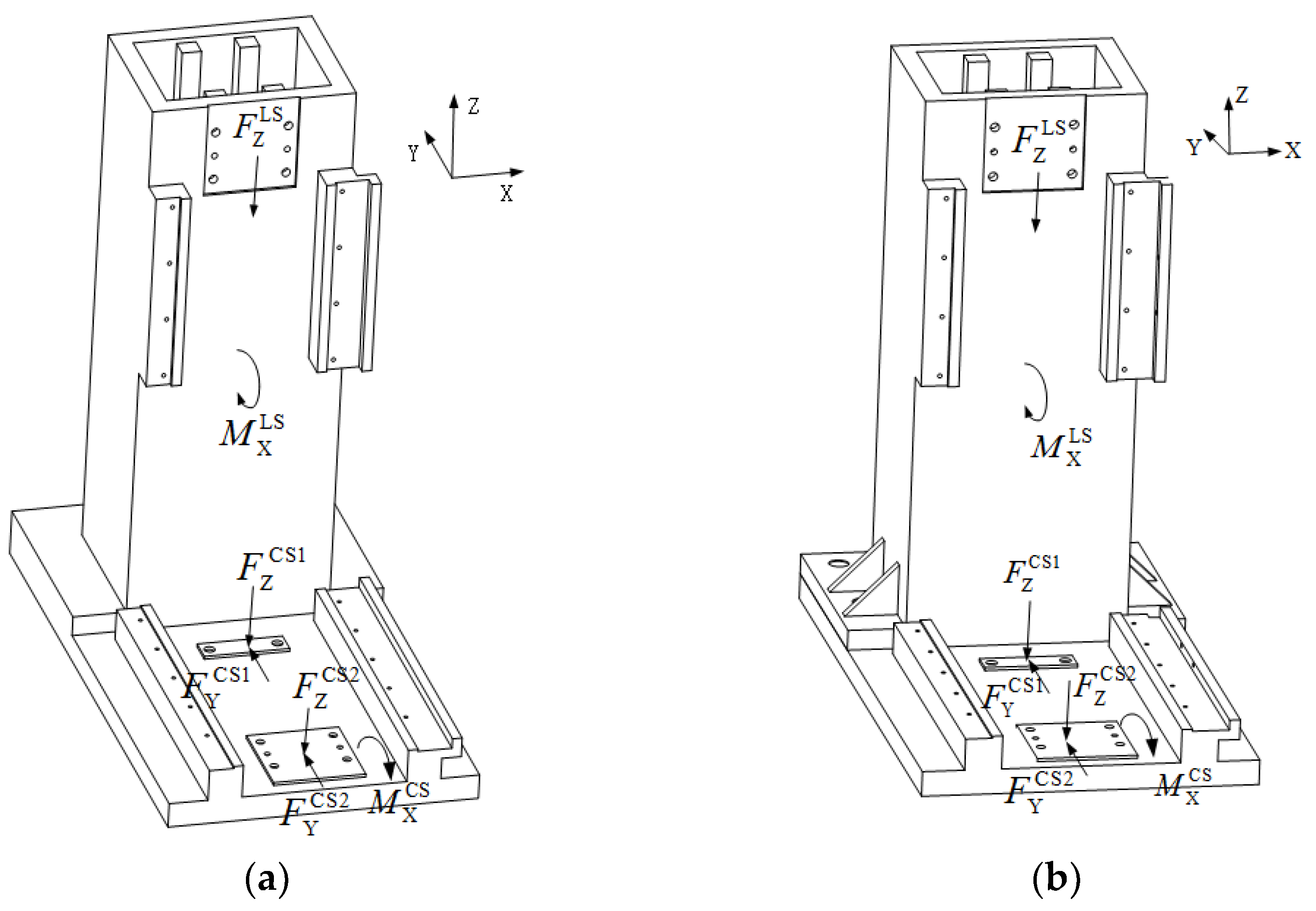
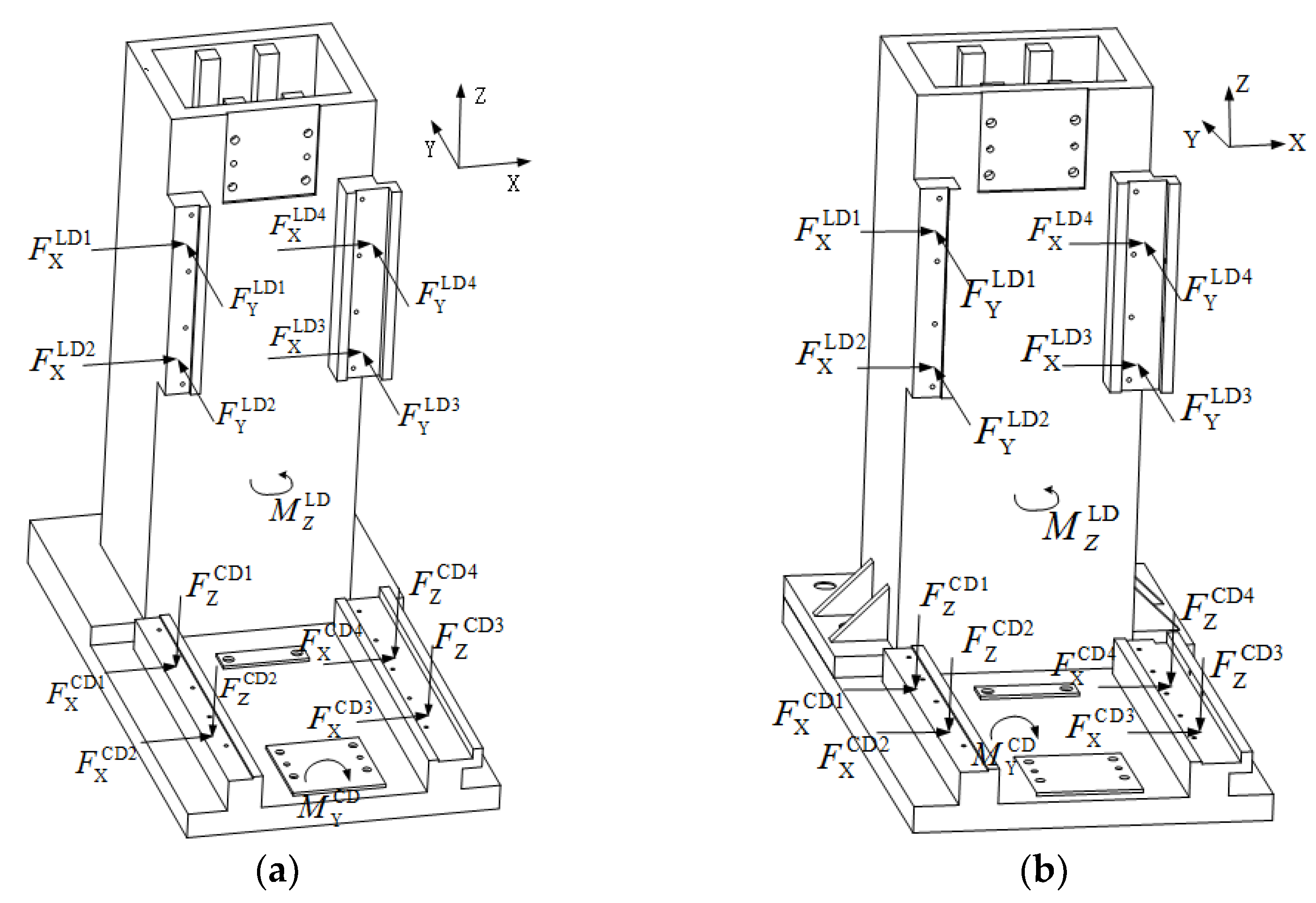
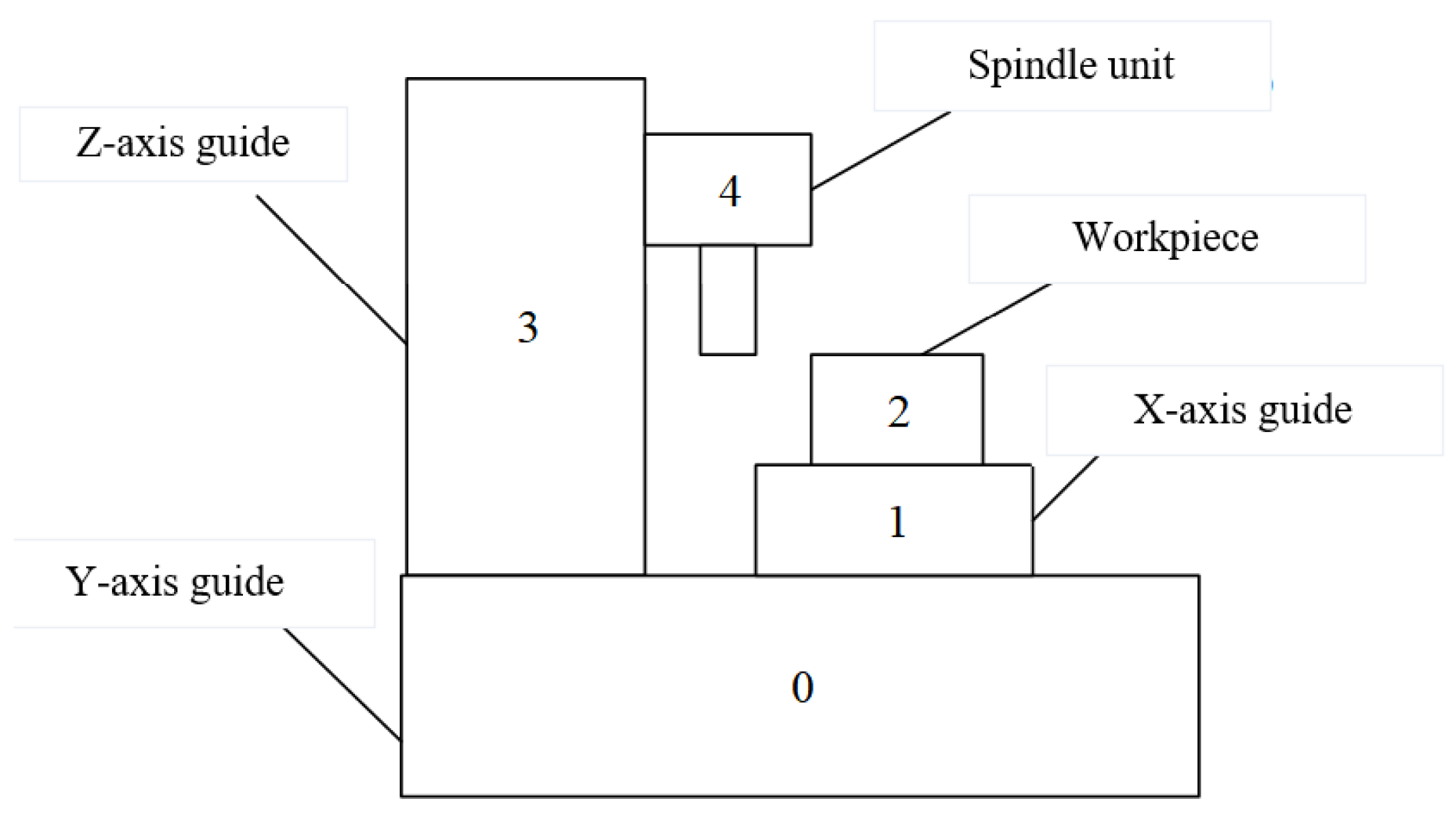
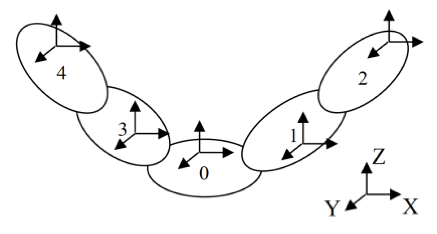
2.1. Structural Scheme and Mechanical Properties

The scheme of micro-machine is shown in Figure 2, which is composed of precision-grade rolling guide unit, precision-grade ball screw unit and servo motor, and the rapid and large-stroke feed of the micro-machine is achieved by macro-moving mechanism. The L-shaped bed structure is adopted, and accordingly the Z-direction vertical feed unit is installed on the column part, and the X/Y-direction horizontal feed system is set at the base part, with the X-axis mounted on the Y-axis. The Z-direction feed unit is supported by one fixed end and one free end, and the X/Y direction uses one fixed end and one supported end.
In order to achieve micro- or sub-micron-level micro-feed, a micro-feed mechanism of piezoelectric ceramics and flexible hinges is adopted. According to the installation space and use requirements of the micro-movement table, a one-dimensional micro-motion mechanism is applied, which is installed on the X-axis horizontal worktable.
In the proposed bed structure in this paper, the deformation of base is mainly controlled by gravity. Since the area of the force-bearing surface and the support surface are relatively large, the deformation of base is extremely small, and the corresponding structural parameters can be determined according to installation requirements. In the bed structure, the column part is the main area producing deformation, and this structure should be designed under the micro-milling condition. The micro-milling force F X M , F Y M , F Z M (Figure 3), and the weight of the main shaft, screw pair and other components are the main factors that cause the deformation of the bed structure. Therefore, it is necessary to calculate the column section parameters in combination with the stress conditions. In addition, the micro-cutting force is small, thus the resulted structural shear deformation is extremely small. Therefore, the column of the micro-machine is mainly designed based on deflection and compression deformation. Based on the micro-milling force, the weight of the parts and the corresponding bending moment, the force and deformation of the column can be deduced by using the theory of material mechanics [17], as shown in Equations (1)–(3).
δ X = F X M h 2 6 E I Y ( 3 H h ) [ δ X ]
δ Y = F Y M h 2 6 E I X ( 3 H h ) + F Z M w 1 H 2 + G w 2 H 2 2 E I X [ δ Y ]
δ Z = ( F Z M + G ) h E A [ δ Z ]
{ I X = L W 3 12 ( L 2 t 1 ) ( W 2 t 2 ) 3 12 I Y = W L 3 12 ( W 2 t 2 ) ( L 2 t 1 ) 3 12
A = L W ( L 2 t 1 ) ( W 2 t 2 )
where, [δi] is the maximum allowable deformation at x, y and z directions respectively; IX and IY represents the moment of inertia at the center of the section around the X and Y axes of the column respectively; A represents the cross-sectional area of……; w1, w2, t1, t2, h, L, W, and H are the length parameters. Among them, w1, w2 and H depend on the actual installation needs of components such as micro-spindle and worktable, and they can be regarded as known parameters. h is the position of spindle tool nose, which can also be regarded as a known parameter. Therefore, the key parameters to be determined in the above formulas are t1, t2, L, and W. Besides, considering structural manufacturability, the wall of column is designed to be equal thickness, that is, t1 is equal to t2. When calculating, Equations (4) and (5) are substituted into Equations (1)–(3) respectively, and the following Equations (6)–(8) can be obtained after simplification.
3 L t 1 W 2 6 L W t 1 2 + 4 L t 1 3 + t 1 W 3 6 W 2 t 1 2 + 12 W t 1 3 8 t 1 4 2 F Y M h 2 E [ δ Y ] ( 3 H h ) + 6 F Z M w 1 H 2 E [ δ Y ] + 6 G w 2 H 2 E [ δ Y ]
3 W t 1 L 2 6 W L t 1 2 + 4 W t 1 3 + t 1 L 3 6 L 2 t 1 2 + 12 L t 1 3 8 t 1 4 F X M h 2 E [ δ X ] ( 3 H h )
2 t 1 ( L + W ) 4 t 1 2 ( F Z M + G ) h E [ δ Z ]
W = ( F Z M + G ) h 2 t 1 E [ δ Z ] + 2 t 1 L
According to the requirements of casting process, the minimum wall thickness of HT300 should meet t1 ≥ 15 mm, and the length L should be larger than the installation width of the guide rail. Therefore, based on work ability and economy, t1 should be determined first, and Equation (8) is simplified to obtain Equation (9), then it is substituted into Equations (6) and (7) to obtain the parameter L, and further W can be obtained. These parameters should satisfy Equations (6)–(8) at the same time. The final overall size of the column determined in this paper is 570 mm × 320 mm × 580 mm, and the wall thickness t1 = 20 mm. In addition, in order to improve the overall rigidity of the column, horizontal and vertical cross-shaped rib plates are arranged inside, as shown in Figure 4.

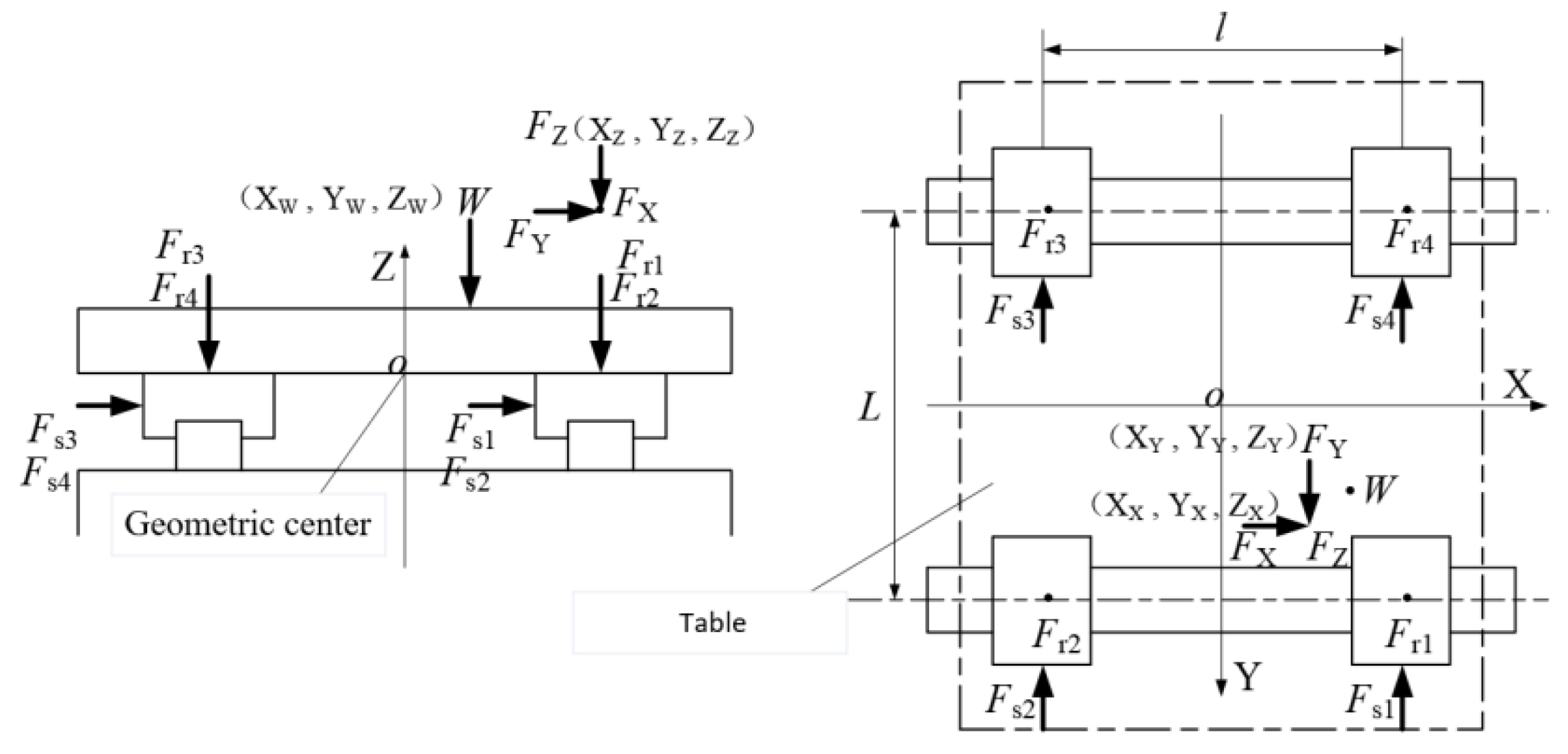
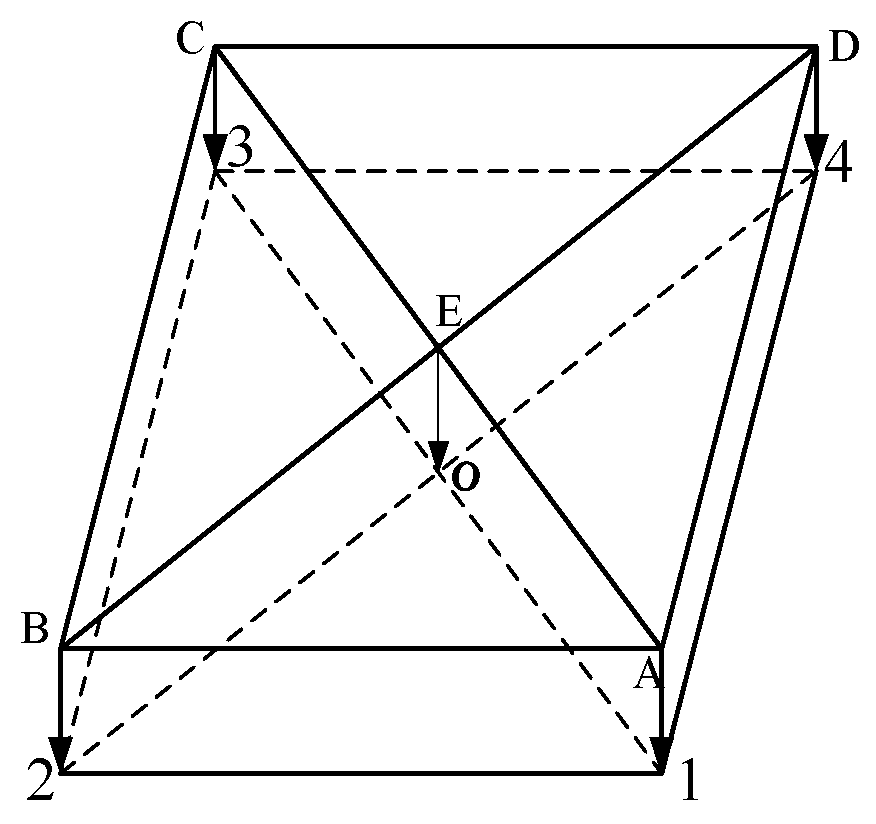
2.2. Precision Linear Guide Unit

The rolling guide unit has small friction coefficient, similar dynamic and static friction coefficients, and good interchangeability, thus it can meet the requirement of motion occasions with high precision. When the micro machine tool is working, the worktables at different coordinate axis must bear external loads in multiple directions, such as the cutting loads FX, FY, FZ and the weight W. The above loads are transmitted to the guide rail slider from the worktable, inducing the slider bears different direction loads, and these loads are the basis for the design of the rail unit. In this section, a single slider is taken as an example to show the calculation process of the force, as shown in Figure 5. The loads born by the slider is defined as Fr, Fs, where Fr represents the load of the slider in the up and down directions, Fs represents the load in the lateral direction, and MX, MY, MZ represent the load around X, Y. Since the point of application of the external load is not at the geometric center of the table, moment is generated at the Z three-axis. In actual work, the size and direction of loads on the slider are not constant, and it would change with the size of the external load or the point of action. But this phenomenon is not considered herein.
Under the action of external load, corresponding force and moment are transmitted by the worktable to the guide rail unit. Taking the load condition of each slider as the analysis object, the loads in the up and down directions of the slider are shown in Figure 5. Based on theoretical mechanics, the static equivalent equations of the slider in the up and down direction and the X/Y axis rotation direction can be established by taking the O point as geometric center, as shown below.
{ F r 1 + F r 2 + F r 3 + F r 4 = F Z + W ( F r 1 + F r 2 ) L 2 ( F r 3 + F r 4 ) L 2 = F Y Z Y + F Z Y Z + W Y W ( F r 1 + F r 4 ) l 2 ( F r 2 + F r 3 ) l 2 = F X Z X + F Z X Z + W X W
F r 1 + F r 3 = F r 2 + F r 4
By simultaneously solving the Equations (10) and (11), the loads Fr1~Fr4 in the vertical direction of each slider of the guide rail pair can be obtained, as shown in Equation (12).
{ F r 1 = F Z + W X 4 + F Y Z Y + F Z Y Z + W Y W 2 L + F X Z X + F Z X Z + W X W 2 l F r 2 = F Z + W X 4 + F Y Z Y + F Z Y Z + W Y W 2 L F X Z X + F Z X Z + W X W 2 l F r 3 = F Z + W X 4 F Y Z Y + F Z Y Z + W Y W 2 L F X Z X + F Z X Z + W X W 2 l F r 4 = F Z + W X 4 F Y Z Y + F Z Y Z + W Y W 2 L + F X Z X + F Z X Z + W X W 2 l
The static equivalent equations of the slider in the lateral direction and the Z-axis rotation direction are established, as shown in Equation (13).
{ F s 1 + F s 2 + F s 3 + F s 4 = F X ( F s 1 + F s 4 ) l 2 ( F s 2 + F s 3 ) l 2 = F X Y X + F Y X Y
It can be seen from Figure 6 that points 1 and 4 are always on the same straight line, with their lengths remaining unchanged, and so as points 2 and 3. According to the displacement coordination conditions [18], points 1~4 have a static relationship as shown in Equation (5).
{ F r 1 + F r 3 = F r 2 + F r 4 F r 1 + F r 2 = F r 3 + F r 4
Finally, by combining Equations (13) and (14), the loads Fs1~Fs4 of each slider of the guide rail pair in the lateral direction can be obtained, as shown in Equation (15).
{ F s 1 = F s 4 = F Y 4 + F X Y X + F Y X Y 2 l F s 2 = F s 3 = F Y 4 F X Y X + F Y X Y 2 l

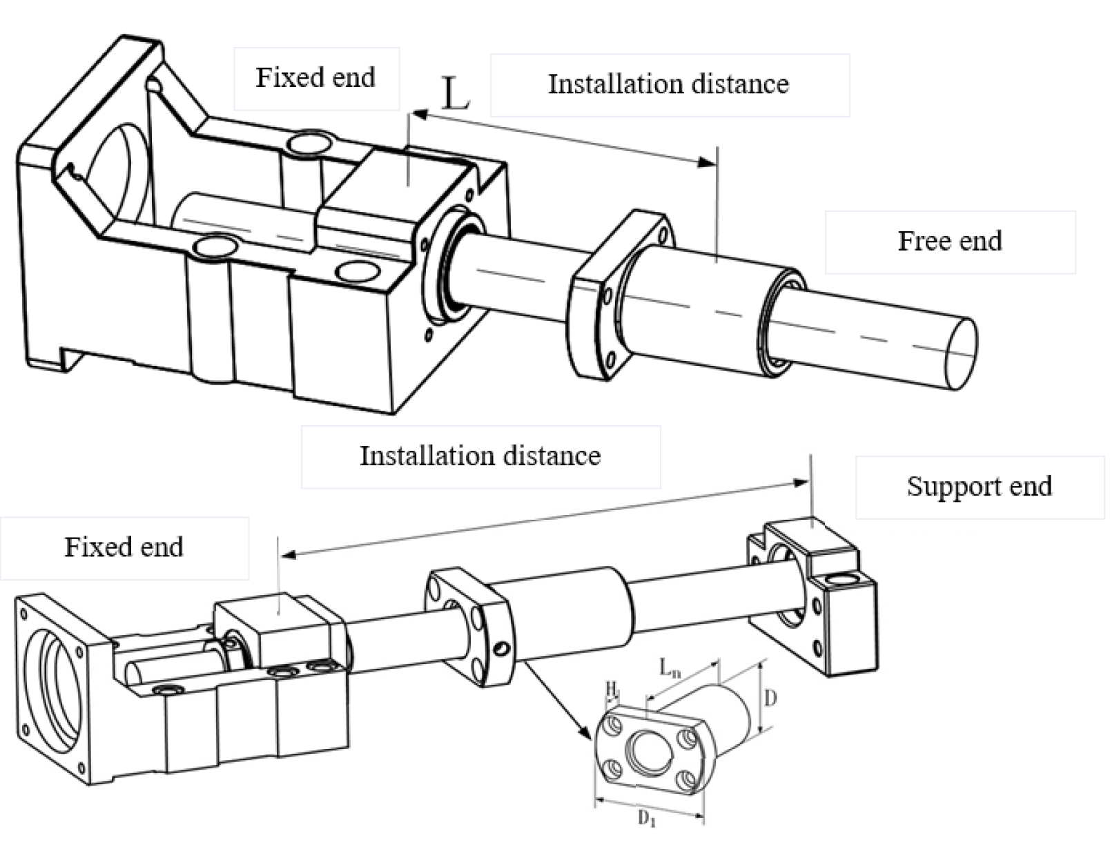
2.3. Ball Screw Unit

As a key transmission component, the ball screw shown in Figure 7 also bears the load from the power end and the load end when transmitting motion and power. Therefore, its basic safety performance must be checked, including the buckling stability, allowable revolutions and rated life, according to the bearing form and use requirements. Since the screw shaft is a slender structure and mainly bears the axial load, and, it should be ensured that the screw has no buckling phenomenon at the largest compression load. Therefore, the buckling stability is one of the main check contents of the screw shaft, and the specific calculation formulas are shown in Equations (16) and(17).
F = α η 1 π 2 E I L 1 2 = η 2 d m 4 L 1 2 × 10 4 F max
and Equation (6) can be simplified as:
d m ( F max L 1 2 η 2 × 10 4 ) 1 / 4
where, F is the allowable buckling load of the screw (N); E is the elastic modulus, 2.06 las5 N/mm2; L1 is the installation distance, L1 = maximum stroke + 0.5 nut length + room for shaft end; I is the minimum second moment of section of the screw shaft (mm), I = π d 1 4 / 64 ; dm is the groove valley diameter of the ball screw (mm); η1, η2 are the coefficients related to installation method, and for fixed-free type, η1 = 0.25, η2 = 1.3; for fixed-support type, η1 = 2, η2 = 10.
Under various milling conditions, the required feed rates and the screw shaft speeds are different. When the speed of the screw shaft is close to its natural frequency, it will easily cause resonance phenomenon and affect the processing process. Therefore, it is necessary to check its dangerous speed, and the specific calculation formula is shown in Equation (18).
N   = β 60 λ 3 2 2 π L 2 2 E I × 10 3 γ A = λ 4 d m L 2 2 × 10 7 N max
where, N max is the allowable dangerous speed (min−1); E is the-elastic modulus, 2.06 × 10⁵ N/mm2; I is the minimum second moment of section of screw shaft (mm), I = π d 1 4 / 64 ; dm is the groove valley diameter of the ball screw (mm); γ is the density of the screw shaft material (7.85 ty−6kg/mm3); L2 is the installation distance; λ1, and λ2 are the coefficients related to installation method.
There are several circles of balls arranged between the screw shaft and the screw nut. When the revolution speed increases, the impact force of the balls will cause damage to the circulating parts. Therefore, it is also necessary to check the allowable revolutions number of the screw unit.
The screw unit is subjected to cyclic stress, either on the rolling surface or on the ball. When the cyclic stress reaches a certain value, the rolling surface will be fatigued and damaged, and the surface will appear fish-scale spalling. This phenomenon is called as surface spalling, and the total number of revolutions of the screw shaft is defined as the life of the ball screw unit. In practical situations, the lifespan of ball screws of the same batch and model is quite different, even if their manufacturing process and the working conditions are the same. Therefore, the screw manufacturers often use the rated life of screw as their life evaluation benchmark. The so-called rated life refers to the total revolution number when 90% of the ball screws reach in the same batch and type work under the same conditions without surface peeling. The speed and load of the ball screw vary with cutting conditions, and they have a non-ignorable impact on the life of the screw at each stage. In order to synthesize the effect of each speed and load, the equivalent speed and equivalent load are introduced herein.
The rotational speed of the ball screw under each cutting condition is N1, N2, N3, …, Nu respectively, and the percentage of the working hours of each rotational speed in the total time is t1, t2, t3, …, tu respectively. The calculation formula of the equivalent rotational speed Nm is shown in Equation (19) as follows.
N m = N 1 t 1 + N 2 t 2 + + N u t u
The axial loads of the ball screw under various cutting conditions are F1, F2, F3, …, Fu, respectively. The calculation formula of the equivalent load is shown in Equation (20).
F m = F 1 3 N 1 t 1 + F 2 3 N 2 t 2 + + F u 3 N u t u N m 3
where, Lh is the rated life; Ca is basic dynamic load rating; and fw is the load factor.

2.4. High Performance Rotary Servo Motor

In the proposed machine, the servo motor is used as the power source of the feed shaft, and its design and selection process needs to calculate the load inertia and load torque of the feed system according to the actual working conditions, then its rated torque and instantaneous maximum torque should be checked. When selecting a servo motor, motor inertia, the lower limit of the rated torque and the maximum torque of the motor based on the load torque are of the same importance. Generally speaking, the load torque under normal operation should be less than 80% of the rated torque of the motor, and the maximum acceleration and deceleration torque should be less than the maximum torque of the motor. During micro-machining, the working load in the heavy-duty cutting is the largest, and the load torque T1 has the following relationship with the rated torque Te of the motor.
0.8 T e T 1   = T a + T p + T u = T a = ( μ W + F a ) P b 2 π υ 1 × 10 3 + 0.014 F a o d m P b + T u
When the machine tool is used for heavy-duty cutting, its acceleration torque TAC should be less than the maximum torque Tmax of the motor, which is:
T m a x T A C   = ( μ W + F a ) P b 2 π υ 1 + 0.014 F a o d m P b + T u + ( J M + J L H ) ( 2 π n 60 t )

3. Static and Dynamic Characteristic Simulation of Bed Structure

3.1. Static and Dynamic Characteristics Simulation Analysis

The bed model does not consider the shape and surface structures since they have little influence on the calculation process, such as bearing seats and guide rail mounting holes. The bed structure material adopts HT300, which is a grey cast iron in pearlitic type. It has high strength and good wear resistance, and is widely used for important castings in machinery manufacturing, such as bed guides, lathes, punches, heavily stressed beds, and headstock gears. The density of HT300 is 7400 kg/m3, the elastic modulus is 122 GPa, and the Poisson’s ratio is 0.29. The specific mesh model of two bed structures is shown in Figure 8.

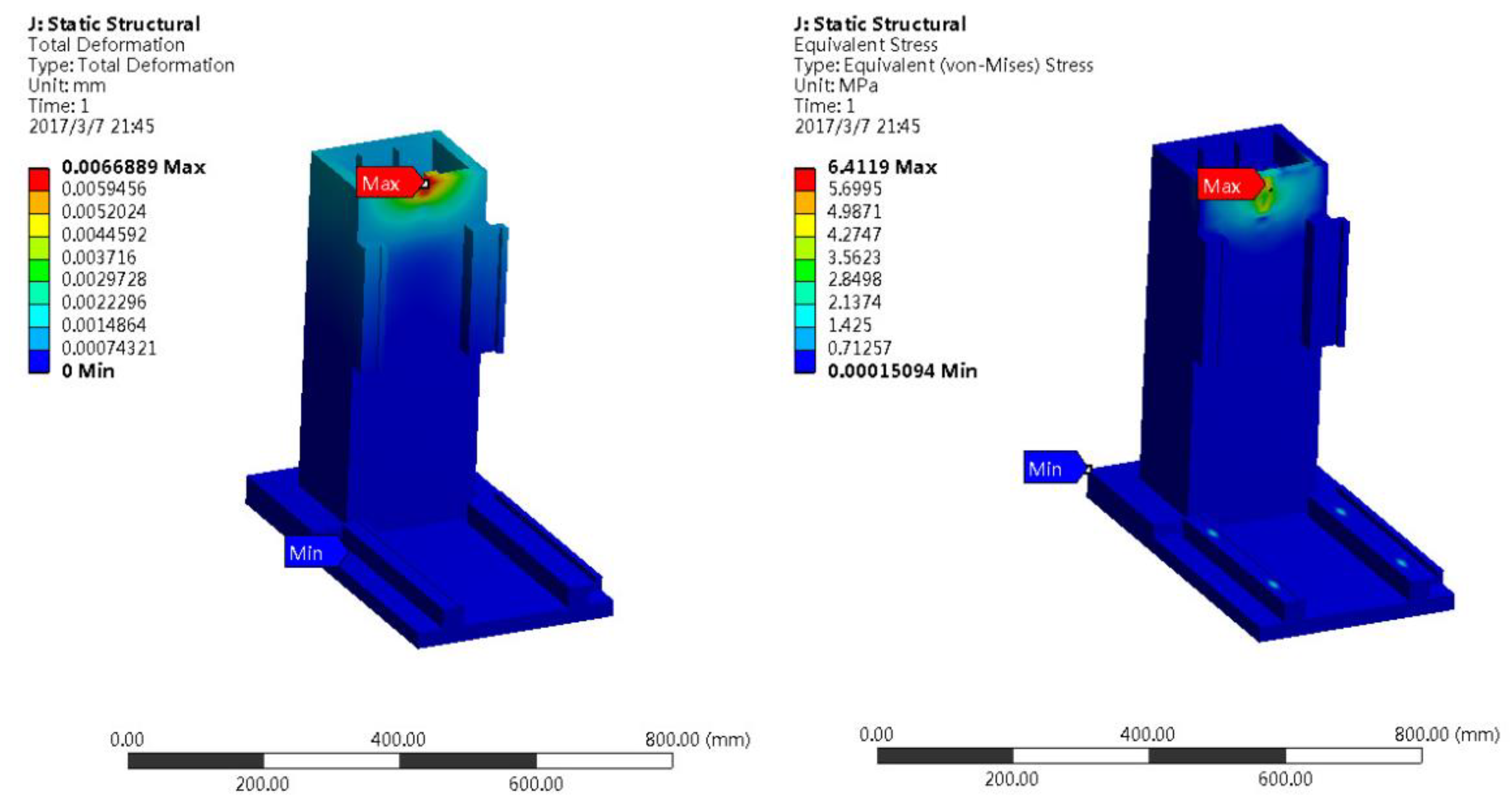
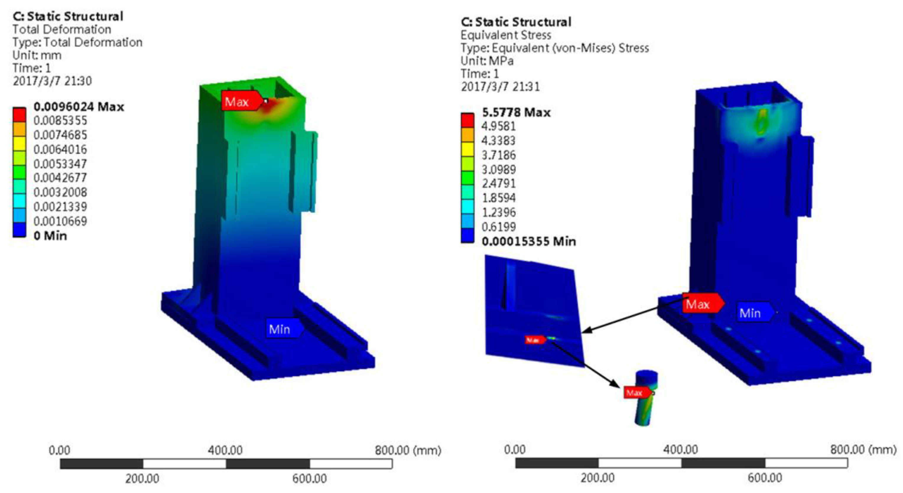
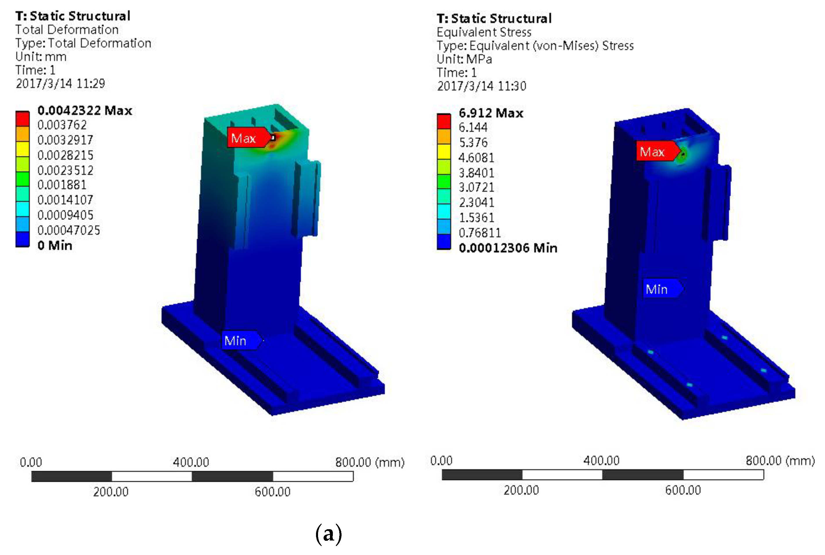
3.1.1. Static Analysis

The micro-milling of aluminum alloy is taken as an example, and a tungsten-carbon-coated carbide flat-end micro-milling cutter is used. The feed rate is 1~9 μm/tooth, and the axial and radial depths of cut are 0.5 mm. The micro-milling forces measured during machining are all less than 4 N. For simulating the most dangerous situation, it is assumed that the micro-milling force in each direction is 4 N [19]. Besides, the weight of the horizontal table supported by the bed G Z CD = 600 N, the weight of the Y-axis screw pair G Z CS = 150 N, and the weight of the Z-axis screw pair of the column = 150 N. The diameters of the micro-milling cutter from the center to the column and the base are different. The distances between the connecting surfaces are L Y 1 = 140 mm, L Y 2 = 115 mm, L Z 1 = 280 mm, and L Z 2 = 250 mm.
In this section, three representative positions of the column table in the motion stroke are used as the analysis conditions. That is, the static analysis is carried out on the upper, middle and lower limit positions of the Z-axis table, thus the load positions applied to the column structure are different. After accomplishing the element mesh by using Hypermesh software, the mesh model is importedinto ANSYS workbench software. The displacement constraint condition is: the bottom of the bed is fixed, and equivalent load is applied to the integral bed and the separate bed shown in Figure 9 and Figure 10. The final simulation results are shown in Table 1 and Table 2.
It can be seen that the maximum stress and maximum deformation of the integral structure both occur at the upper front end of the column, and the maximum deformation of the separate structure also occurs at this position, but the maximum stress point occurs at the bolt directly behind the column. The maximum deformation of the integral bed structure is 6.69 μm (Figure 11), which is about 30.3% less than that of the separate bed structure of 9.60 μm (Figure 12). This is mainly due to the fact that there is a contact gap between the column of the separate bed structure and the bed, and the gap of the contact area increases under applied force, which increases the overall deformation of the column part. In terms of the maximum Von Mises stress, the integral structure is slightly larger than the separate structure, but both are much smaller than the yield strength of cast iron of 195 MPa, which is within a reasonable stress range.

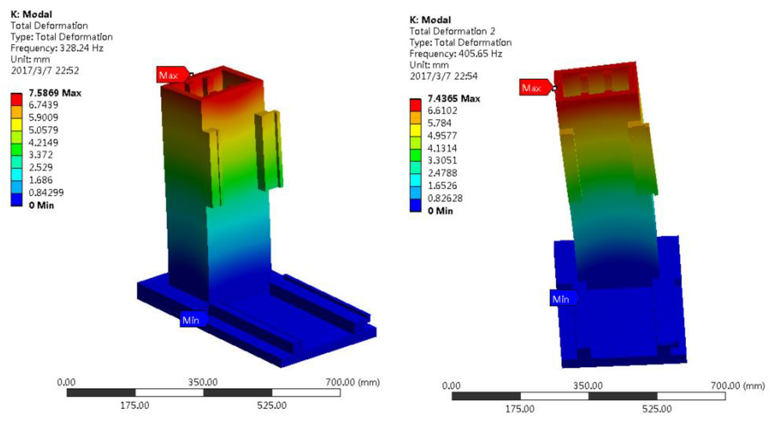
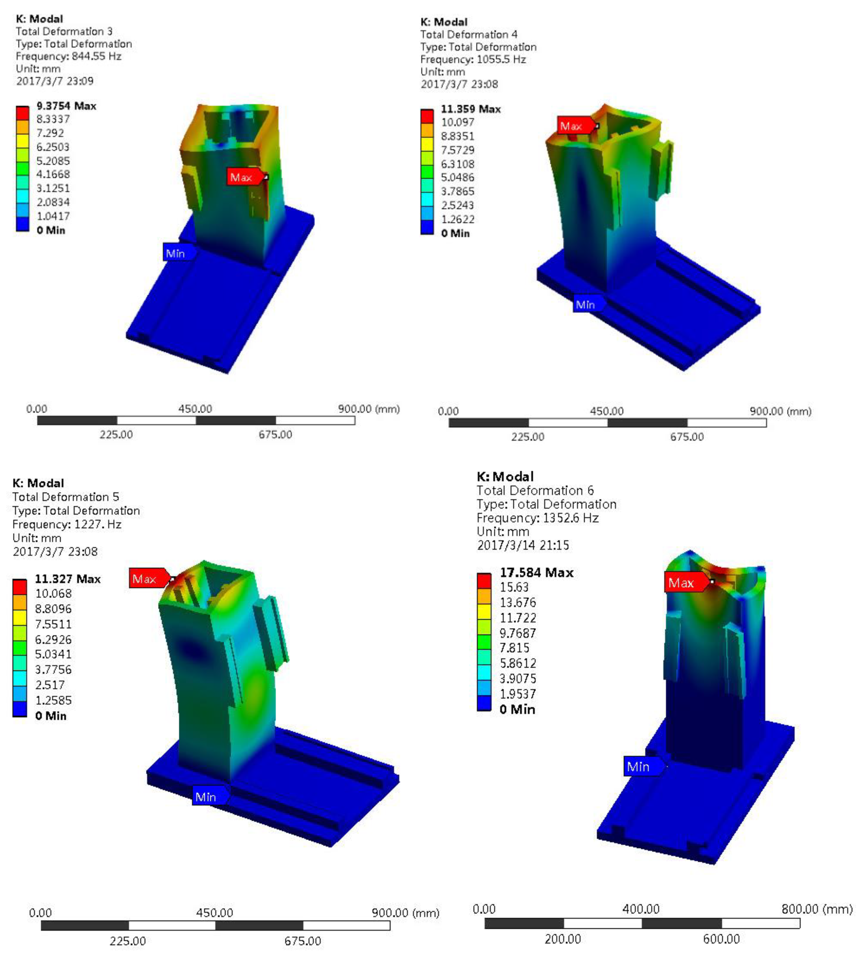
3.1.2. Modal Analysis

The structural mode is the inherent property of the elastic body. Through modal analysis, the natural frequency and mode shape of the geometric structure can be obtained, and further the dynamic characteristics of different bed structures can be revealed. When the excitation frequency inside or outside the machine tool is close to its natural frequency, resonance will appear in the machine tool, which reduces the machining accuracy and affects the machining quality. In this paper, the influence of machine tool structure on its natural frequency is studied to avoid resonance phenomenon. In this paper, the first six modes of the integral and separate structures are calculated, and the analysis results are shown in Table 3 and Table 4, and the first six modes of the integral structure are shown in Figure 13.
It can be seen that the natural frequencies of each order of the integral structure and the separate structure are similar, and the mode shapes and the maximum amplitude positions of each order are basically the same as well. The displacement of the mode shape is a dimensioned relative value, and has no reference value. The actual vibration displacement can refer to the harmonic response analysis in next section.

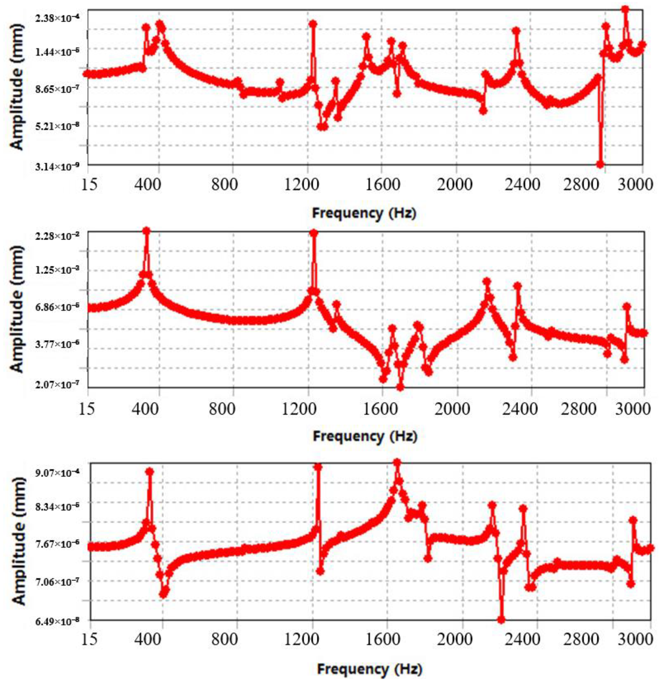
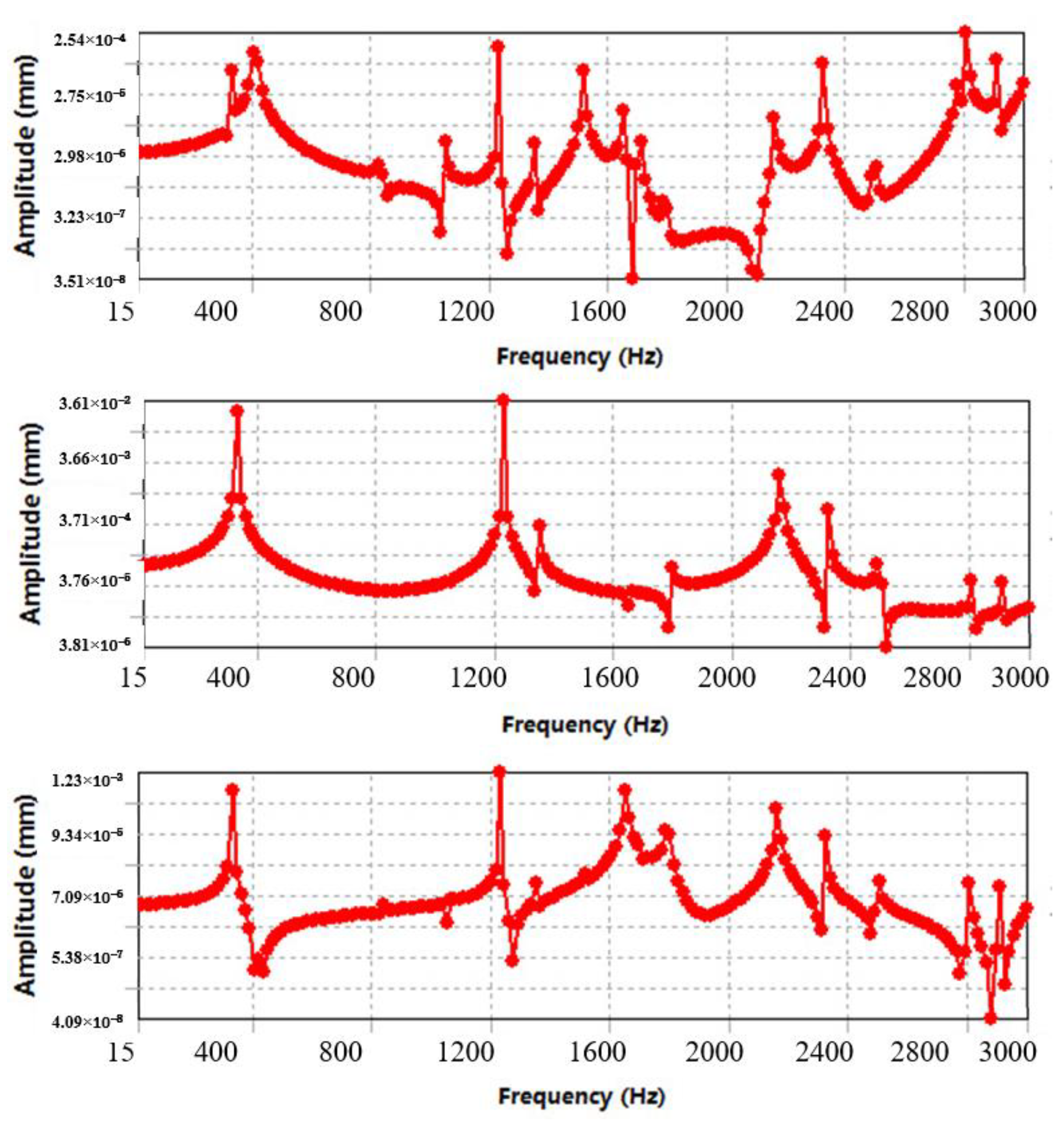
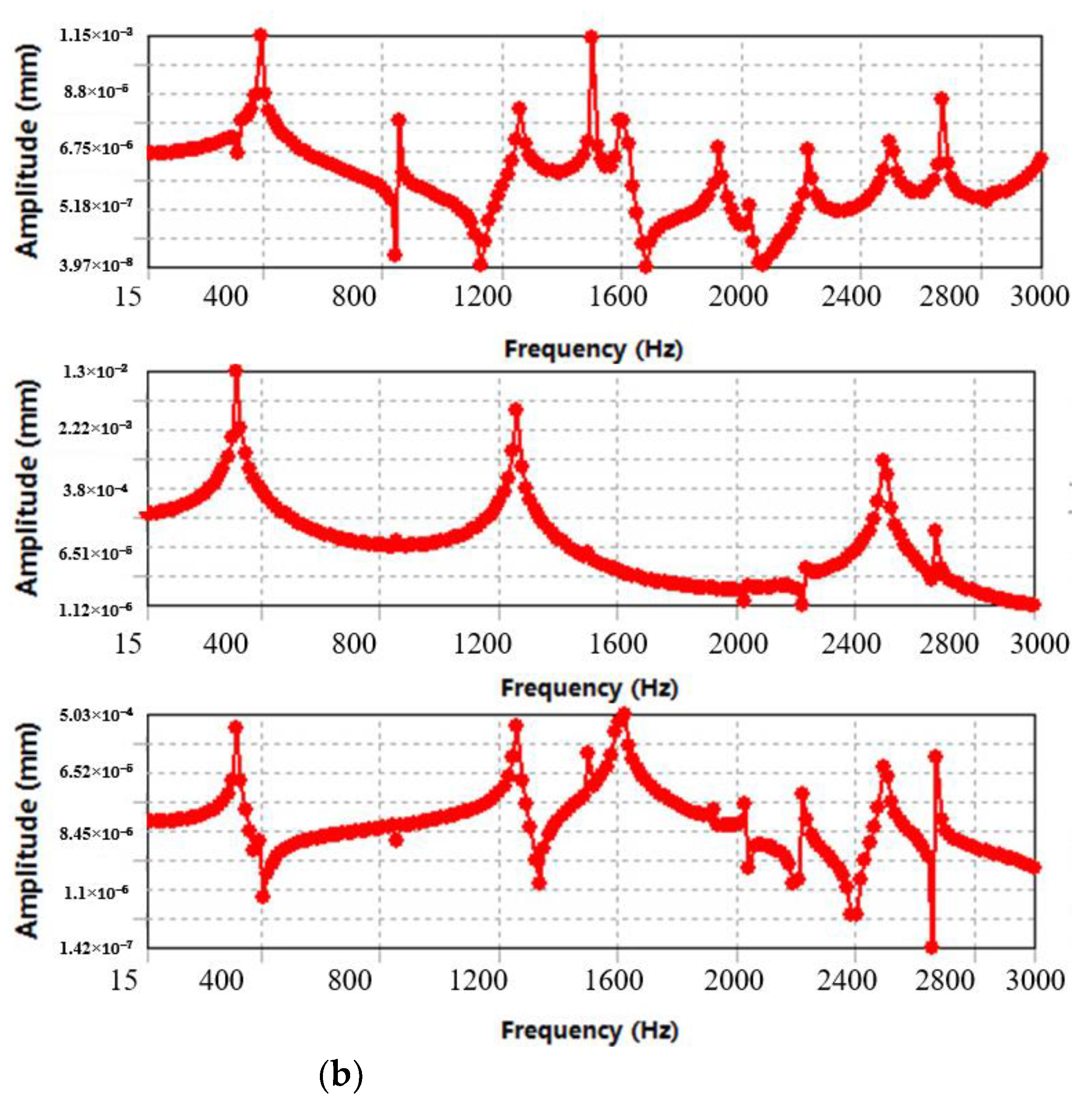
3.1.3. Harmonic Response Analysis

The micro-milling force and spindle excitation act on the bed structure are periodic loads. Through harmonic response analysis, the resonance frequency and the amplitude of the bed structure can be effectively identified, which provides an important reference for further optimizing the bed structure. In this paper, harmonic response analysis of the integral and separate bed structures is carried out respectively in the frequency spectrum range of 0~3000 Hz. According to the simulation results, the maximum common amplitude values of the integral and separate bed structures are at the lower limit and the upper limit of the column, respectively, as shown in Figure 14 and Figure 15.
It can be seen from Figure 14 and Figure 15 that the two structures resonate at different natural frequencies, and the amplitudes of the integral structure are smaller than those of the separated structure in all directions. Among them, the common amplitude values in the X-axis and Z-axis directions are small, but the that in the Y-axis direction is large. This phenomenon indicates that the bed structure is greatly affected by the Y-direction load, which is consistent with the stress of the structure. At the same time, the amplitudes of the two structures at the first five-order natural frequencies are relatively large, with the maximum peak value of 36.09 μm, which exceeds the allowed variation range of the micro-machine tool. When the frequency of the micro-milling force is around 450 Hz or higher than 2000 Hz, the dangerous vibration can be effectively avoided. The vibration frequency of the main shaft is closely related to its rotational speed. If the rotational speed of the main shaft is guaranteed to be above 100,000 revolutions, the harmful vibration caused by the main shaft can be avoided.

3.2. Structural Optimization

To further improve the dynamic and static rigidity of the bed structure and reduce its maximum deformation, the overall bed structure is optimized based on the above simulation results. The mechanical properties of the bed structure are shown in Figure 16. From Figure 16, it is shown that the maximum static deformation is 4.23 μm, which is 36.7% lower than that before optimization. In addition, the first six natural frequencies are 317.39 Hz, 391.08 Hz, 854.12 Hz, 1256.71 Hz, 1499.90 Hz, and 1594.72 Hz, respectively, indicating that except that the first and second order natural frequencies are slightly lower than those before optimization, the other natural frequencies have been greatly improved. Besides, in Figure 16, it can also be seen that the structural common amplitude values in the Y-axis and Z-axis directions are lower than those before optimization, while the amplitude in the X-axis direction is increased, and the overall harmonic response presents improved characteristics. It can be concluded that the dynamic and static characteristics of the optimized bed structure have been significantly improved.

4. Performance Test of Micro-Machine Prototype

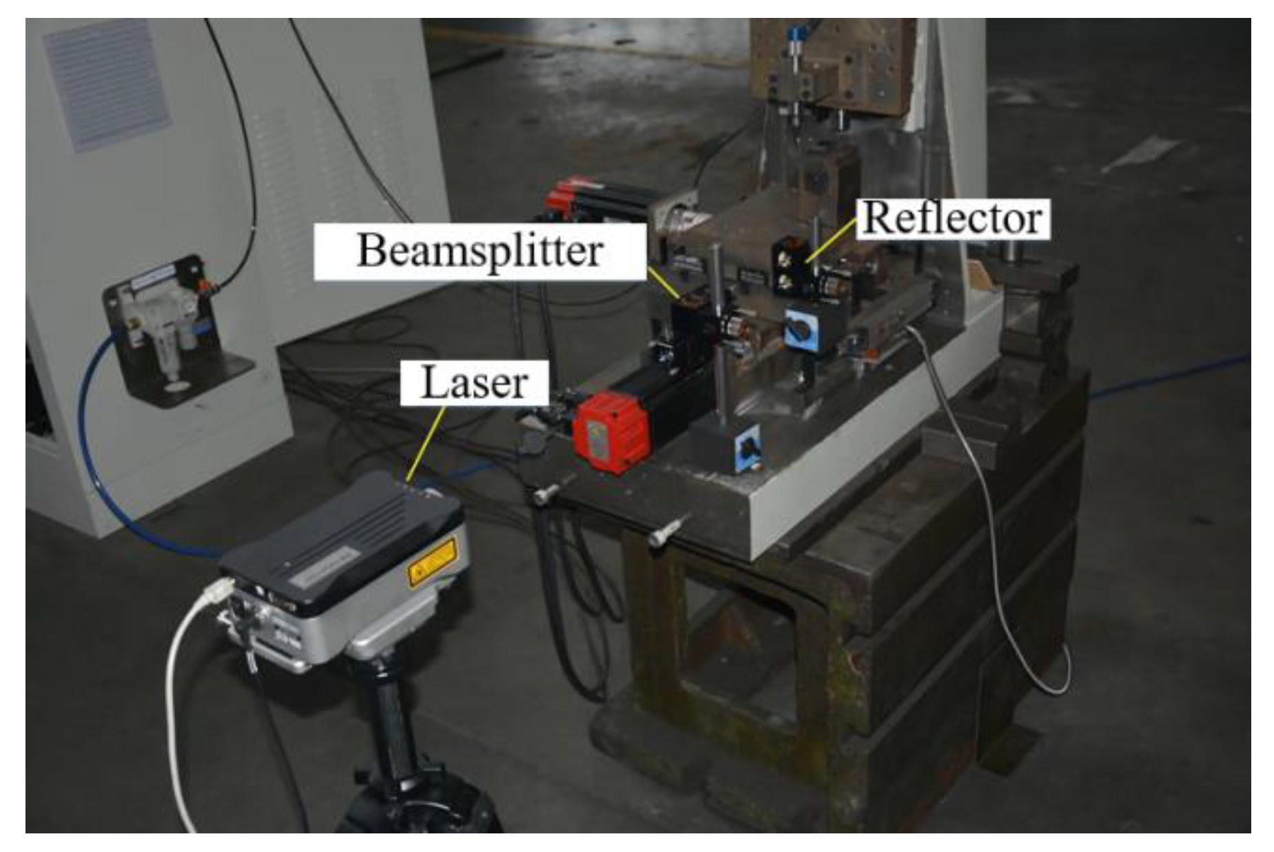
4.1. Accuracy Detection

Based on each sub-unit, the micro-machine is simplified into a multi-body system through topology structure, and the correlation of each unit body in the topology structure is described by a low-order array. Through establishing a generalized coordinate system of the multi-body system, the relative positions, attitudes and changes of each sub-unit can be expressed with a homogeneous characteristic matrix. Figure 17 and Figure 18 is a schematic diagram of the overall structure of the micro machine tool, in which the Y-axis guide rail is installed on the Y-axis base (or part of the bed).
Optional body Bj is used as a typical body of multi-body system, and the sequence number of the n-order low-order body of body Bj is defined as:
L n ( j ) = i
In Equation (23), L is defined as the low-order body operator, and body Bj is called as the n-order high-order body of body Bi. It satisfies:
L n ( j ) = L ( L n 1 ( j ) )
and the following definitions are added:
L 0 ( j ) = j
L n ( 0 ) = 0
When body Bi is the adjacent low-order body of body Bj, there will get L(j) = i.
In order to establish the spatial geometric model of the micro-machine tool with high accuracy, 21 basic geometric errors are defined, which mainly involve the linear motion error and mutual position error of the coordinate axes. There exist two basic states of between adjacent units of the micro-machine, i.e., the relative static state and relative motion state. When adjacent bodies are fixedly connected, they not only have the ideal fixed connection position and attitude (referred to as pose), but also have a static pose error in the direction of 6 degrees of freedom, which is called as the actual static error. When the neighbors are in relative motion, there is a relative static state at the beginning of the motion and a subsequent relative motion state. Therefore, when describing the two adjacent bodies that are in relative motion, it should not only consider the ideal relative static posture and the actual static error, but also consider the ideal motion pose and motion pose error caused by motion error.
The ideal motion of the typical body Bj relative to the low-order body Bi is equivalent to the ideal motion of the local coordinate system Oj—XjYjZj of the body Bj relative to the local coordinate system Oj—XjYjZj of the body Bi, and the motion process involves the three coordinate axes of X/Y/Z of rotation and shafting translation. Therefore, the ideal pose homogeneous transformation matrix of the coordinate system Oj—XjYjZj relative to the coordinate system Oi—XiYiZi and the homogeneous transformation matrix of the motion error are as follows:
T i j s = [ 1 γ i j β i j x i j γ i j 1 α i j y i j β i j α i j 1 z i j 0 0 0 1 ] ,   Δ T i j s = [ 1 ε i j z ε i j y δ i j x ε i j z 1 ε i j x δ i j y ε i j y ε i j x 1 δ i j z 0 0 0 1 ]
In this section, the homogeneous transformation characteristic matrix between adjacent subunits of the micro-machine tool will be established respectively, which mainly include the relatively static ideal characteristic matrix and its error characteristic matrix, and the ideal motion characteristic matrix and its error characteristic matrix. The worktable unit is defined as “w” and the tool clamping unit (spindle unit) is defined as “t”. Only when the high-order body is a worktable unit or a tool clamping unit, the unit name “d” can be used, and the other bodies use adjacent units body serial number. For non-moving parts and fixed coupling units, since their errors are small or easy to eliminate, their ideal characteristic matrix and error characteristic matrix are adopted as the unit matrix I4×4 in this section. In addition, the homogeneous feature matrix for the adjacent unit cells is defined as follows, the matrix with subscript “p” or “s” represents the ideal stationary or ideal motion feature matrix of the adjacent unit cell, respectively, and Δ represents the error feature matrix.
The motion accuracy of the coordinate axis is evaluated, which mainly include the detection (repeated) positioning accuracy and reverse deviation. In this study, Renishaw XL-80 laser interferometer (Figure 19) was used to test the motion accuracy of the coordinate axis of the prototype. The measurement results in Figure 20 show that the positioning error of the X, Y and Z axes in the effective feed stroke is less than 5 μm, 4 μm and 3.5 μm, respectively, the repeated positioning error is less than 1.5 μm, 0.5 μm and 1.5 μm, respectively, and the reverse error of each axis is less than 0.5 μm. For micro-cutting, the motion accuracy of each coordinate axis fully meets the application requirements. In addition, the positioning accuracy of the X, Y, Z three-coordinate axes also preliminarily verified the reliability of the spatial geometric accuracy model in this paper, which lays a theoretical foundation for the geometric accuracy design and analysis of subsequent prototypes.

4.2. Experimental Verification

The micro machine tool is composed of two parts: the electrical system and the mechanical system. The electrical system includes electrical control principle, power supply circuit of each control unit, selection of the numerical control system and application of the servo control method. The mechanical system mainly includes processing of non-standard parts, assembly of machine tool components and whole machine and geometric accuracy testing of parts. After completing the assembly and debugging of the prototype, performance test and the micro-milling and micro-grinding processing test of the micro-machine tool are carried out.
In order to verify the multi-axis linkage and actual processing capability of the micro-machine prototype (Figure 21) for micro-cutting, this paper takes 6061 aluminum alloy and single-crystal silicon materials as the processing objects, and micro-milling and micro-grinding tests are carried out on the prototype. Processing procedure: No cutting coolant is used in the micro-machining process, and the coordinate axis of the prototype adopts a domestic Hengxing star grating ruler with a resolution of 0.1 μm.
Two micro-milling processing experiments were carried out on 6061 aluminum alloy. The first one is the processing of micro-surface structure based on three-axis linkage, and the other one is the processing of regular micro-rectangular structure based on horizontal axis linkage. The machining process uses a carbide micro-milling tool (shown in Figure 22), and its specific parameters are shown in Table 5. As shown in Figure 23, the micro-spherical surfaces and micro-arc grooves are processed under the spindle speed of 30,000 rpm, the feed rates of 1.6 mm/min and 1.8 mm/min, and the maximum milling depths of 0.6 mm and 0.4 mm, respectively. The test results show that the micro-machine prototype has good multi-axis linkage performance. Besides, the micro-structures machined have clear geometric outlines and no obvious quality defects on the machined surface.
In order to further test the processing performance of the prototype, a micro-grinding test was carried out on the single-crystal silicon material, and the tool of an electroplated diamond micro-grinding rod was used, as shown in Figure 24. The geometric parameters of the abrasive material are shown in Table 6. During machining process, the working speed of the spindle is set as 40,000 rpm, the feed rate of the horizontal axis is set to be 0.5 mm/min, and the grinding depth of the Z axis is 50 μm. The formed geometry is shown in Figure 25, and the scale of the square frame in the figure is 1 mm. From this figure, it is shown that the geometric outline of the micro-groove structure is clear and the quality of the machined surface is good. In addition, the same micro-grinding test at the feed speed of 3 mm/min and 6 mm/min was carried out. The comparison shows that the smaller the feed speed of the coordinate axis, the better the surface quality of the workpiece.

5. Conclusions

In this paper, a micro-machine tool integrated with bed structure for micro-cutting is fabricated and tested, and the dynamic and static mechanical properties of the structure under the various working conditions are studied. The overall structure has been optimized based on parameter analysis. The conclusions are as follows:
(1)
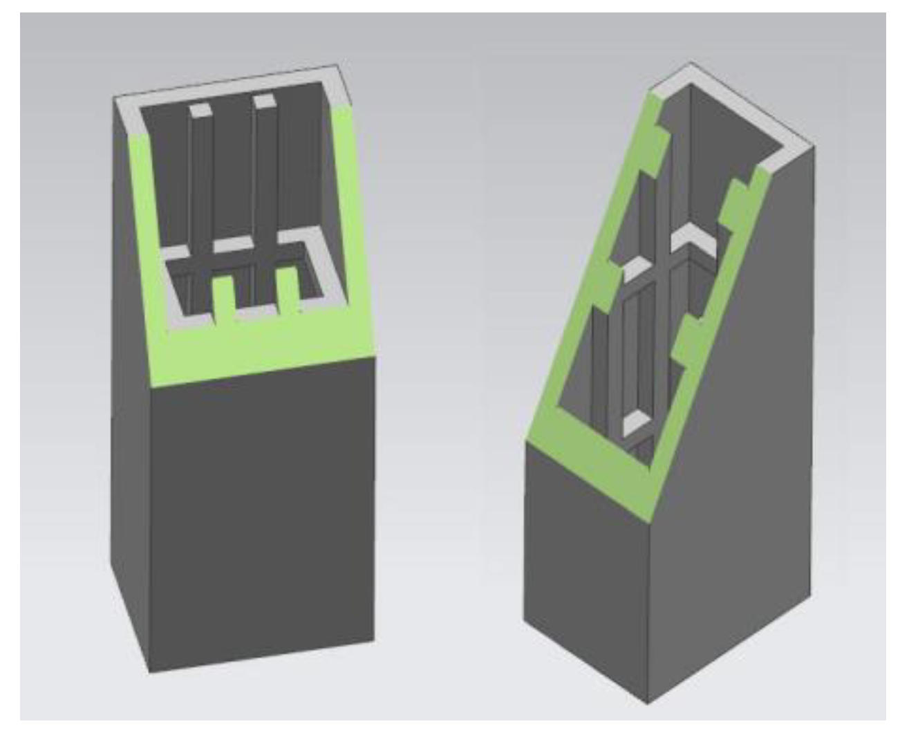
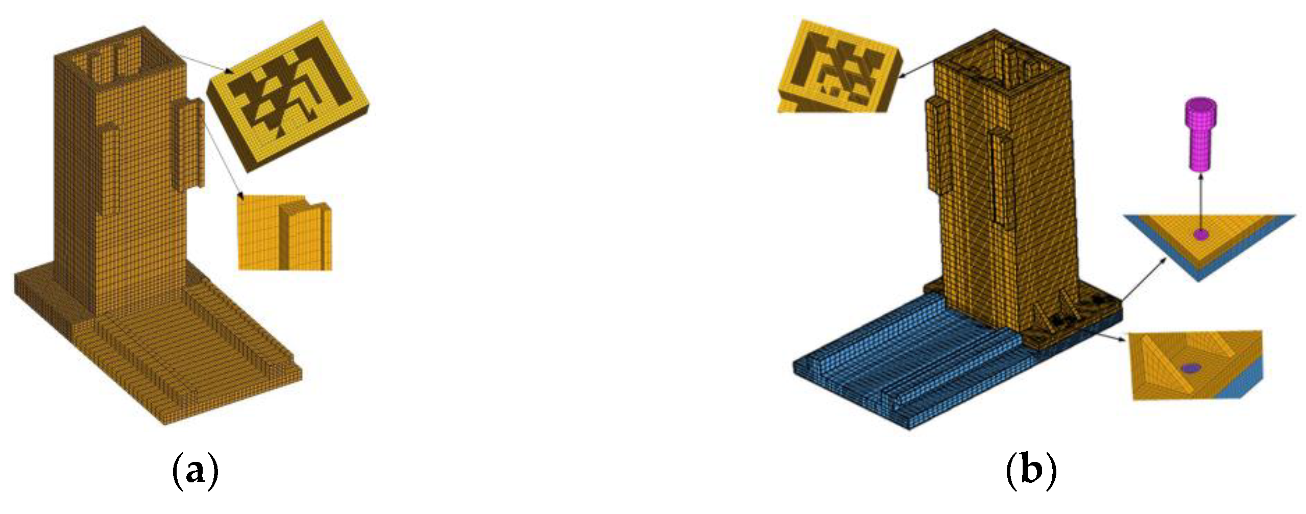
The integral bed structure is significantly superior to the separate structure in terms of the maximum static deformation and harmonic response amplitude, and its maximum stress is much smaller than the yield strength of material. Compared with the assembled separate bed column, the integral bed structure can ensure the verticality between the bed columns at one time when casting the blank, which can more easily meet the requirement of relevant position accuracy. Therefore, the integral bed structure has better comprehensive mechanical properties.
(2)
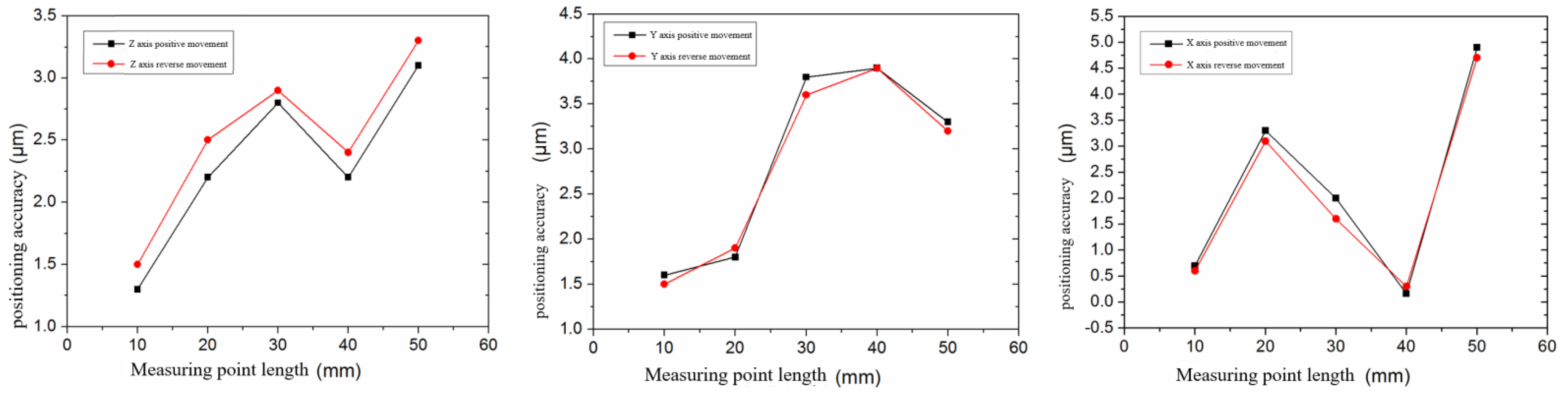
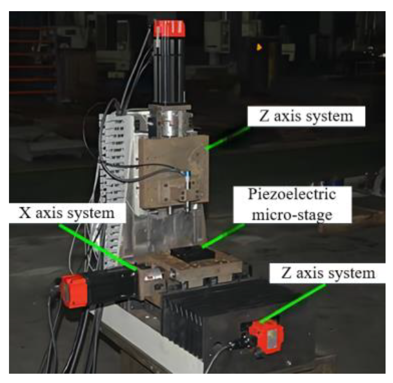
A prototype of a micro-machine tool for micro-cutting was developed, and the motion accuracy of the coordinate axes of the prototype was tested. The results show that the positioning error of the X-axis is the largest, and the positioning error of the Z-axis is the smallest, which preliminarily verifies the reliability of the spatial geometric accuracy model of the micro-machine.
(3)
Only the number and arrangement of the ribs in the column are changed in the optimized integral bed structure, with simple structure and good mechanical properties. The positioning error of each macro-moving coordinate axis in the effective travel range is less than 5 μm. The repeated positioning accuracy of the Y axis is the highest, and the repeated positioning error and reverse error of each axis is less than 1.5 μm and 0.5 μm, respectively.
(4)
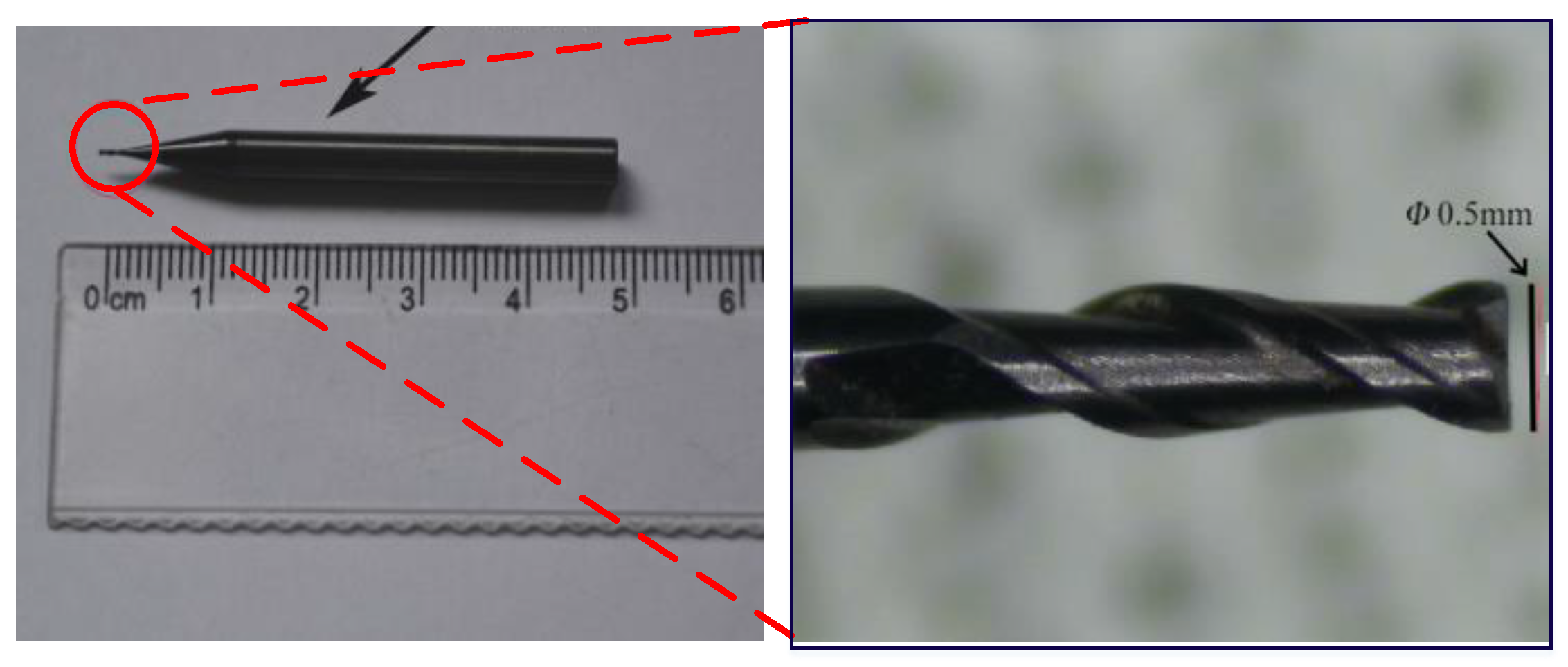
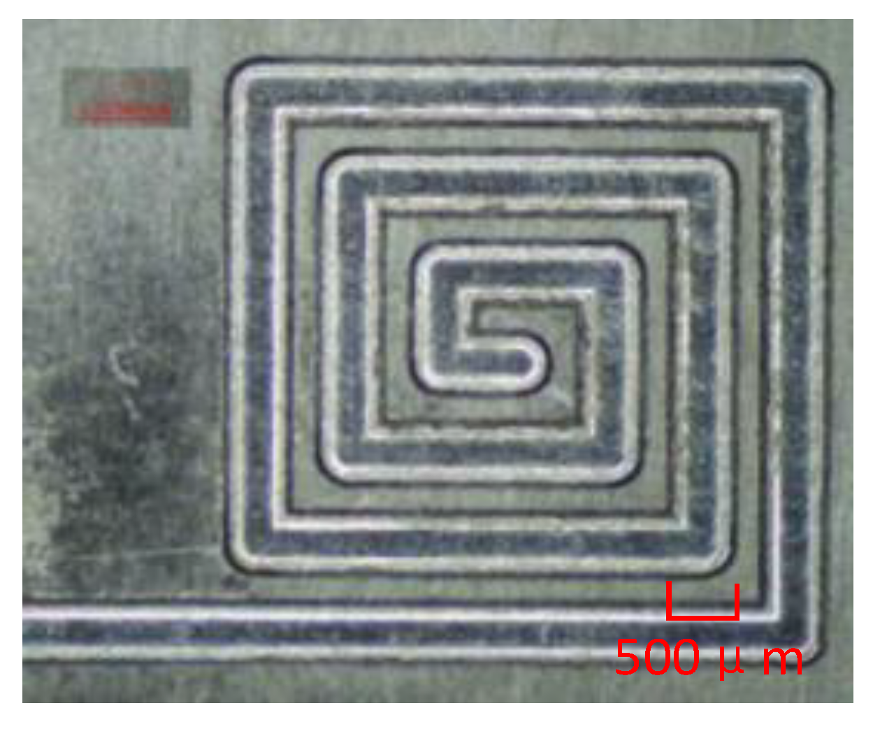
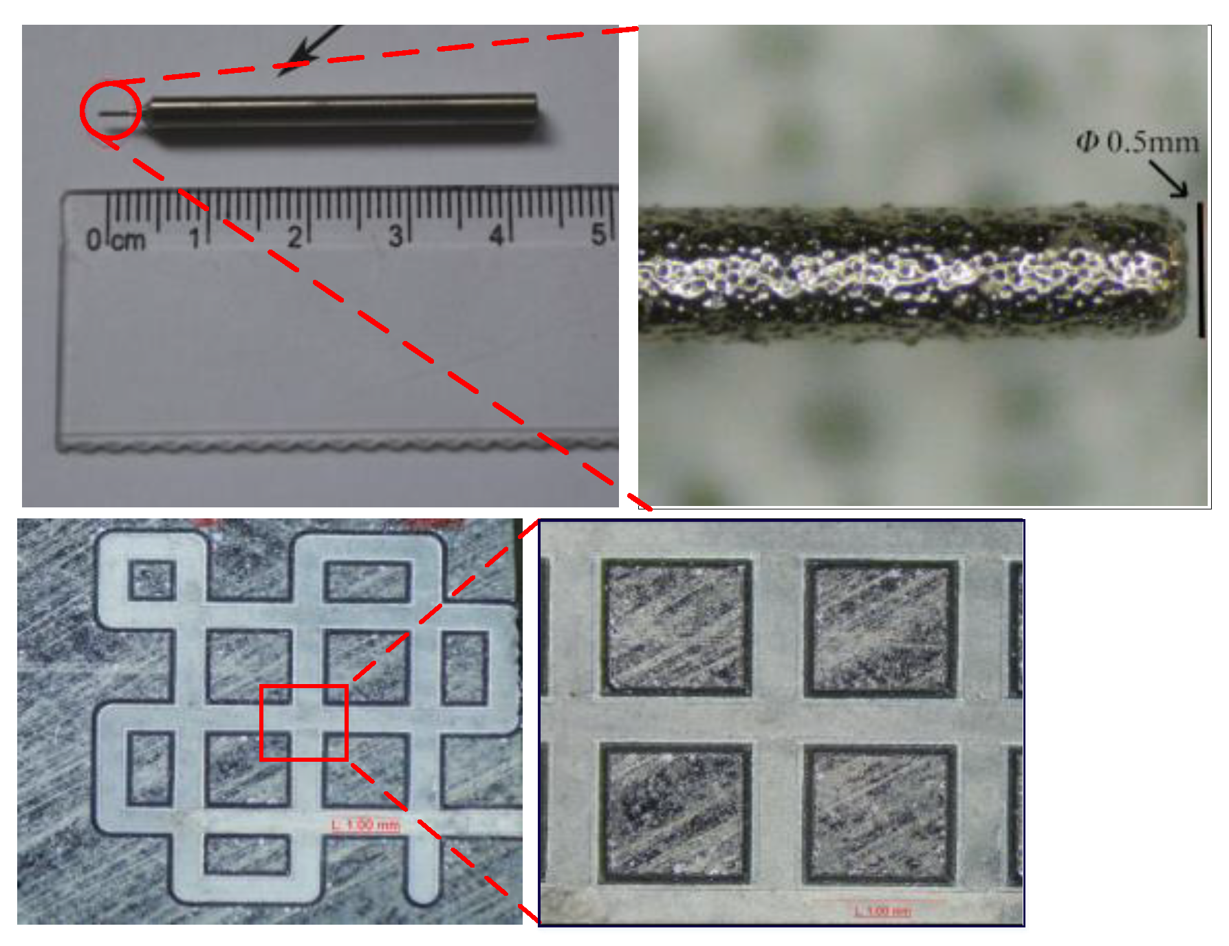
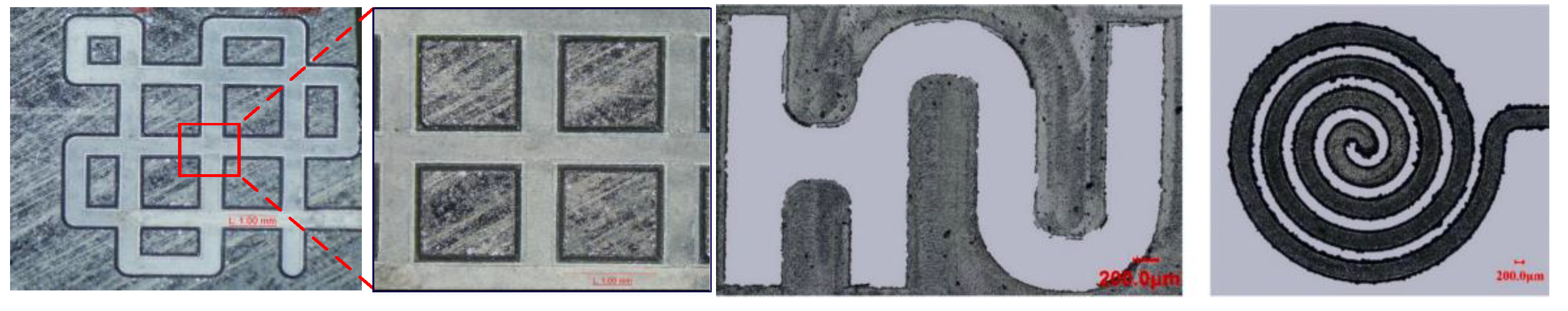
Micro-milling and micro-grinding experiments were carried out on 6061 cemented carbide and single-crystal silicon materials. The machining results show that the prototype has good multi-axis linkage, and its machining performance fully meets the design and application requirements.

Author Contributions

Conceptualization, X.H. and H.X.; methodology, S.L.; software, W.L.; validation, X.H., H.X. and W.L.; formal analysis, X.H.; investigation, S.L.; resources, S.L.; data curation, H.X.; writing—original draft preparation, X.H. and H.X.; writing—review and editing, W.L.; visualization, H.X.; supervision, W.L.; project administration, W.L.; funding acquisition, W.L. All authors have read and agreed to the published version of the manuscript.

Funding

National Natural Science Foundation of China (51875192), the Excellent Youth Project of Educational Committee of Hunan Province (20B067) and the Natural Science Foundation of Hunan Province of China (2020JJ5617) and Open Research Fund of State Key Laboratory of the High Performance Complex Manufacturing of Central South University (Kfkt2019-09).

Institutional Review Board Statement

Not applicable.

Informed Consent Statement

Not applicable.

Data Availability Statement

Not applicable.

Acknowledgments

The authors would like to deeply appreciate the support from National Natural Science Foundation of China (51875192), the Excellent Youth Project of Educational Committee of Hunan Province (20B067) and the Natural Science Foundation of Hunan Province of China (2020JJ5617) and Open Research Fund of State Key Laboratory of the High Performance Complex Manufacturing of Central South University (Kfkt2019-09) and the Hunan Provincial Key Laboratory of High Efficiency and Precision Machining of Difficult-to-cut Material of Hunan University of Science and Technology.

Conflicts of Interest

The authors declare no conflict of interest.

References

  1. Sun, Y.; Jin, L.; Liu, M.; Gong, Y.; Sun, Y.; Liu, M. A comprehensive review on fabrication of ultra small micro tools via electrical discharge machining-based methods. Int. J. Adv. Manuf. Technol. 2021, 1–33. [Google Scholar] [CrossRef]
  2. Das, A.; Shukla, S.; Kumar, M.; Singh, C.; Chandravanshi, M.L.; Bajpai, V. Development of a vibration free machine structure for high-speed micro-milling center. Int. J. Adv. Manuf. Technol. 2021, 116, 3489–3506. [Google Scholar] [CrossRef]
  3. Kshirsagar, N.; Tayade, R.M. A review of sequential micro-machining: State of art approach. Mater. Today Proc. 2022. [Google Scholar] [CrossRef]
  4. Uriarte, L.; Herrero, A.; Ivanov, A.; Oosterling, H.; Staemmler, L.; Tang, P.T.; Allen, D. Comparison between microfabrication technologies for metal tooling. J. Mech. Eng. Sci. 2006, 220, 1665–1676. [Google Scholar] [CrossRef]
  5. Ramesh, J.; Ram, M.M.; Varadarajan, Y.S. Barrier mitigation strategies to the deployment of renewable and energy-efficient technologies (REET) in micro and small manufacturing clusters. Mater. Today: Proc. 2022, 52, 1622–1632. [Google Scholar] [CrossRef]
  6. Chae, J.; Park, S.S.; Freiheit, T. Investigation of micro-cutting operations. Int. J. Mach. Tools Manuf. 2006, 46, 313–332. [Google Scholar] [CrossRef]
  7. Wang, Y.; Geng, Y.; Yan, Y.; Wang, J.; Fang, Z. Robust model predictive control of a micro machine tool for tracking a periodic force signal. Optim. Control. Appl. Methods 2020, 41, 2037–2047. [Google Scholar] [CrossRef]
  8. Li, W.; Liu, M.; Ren, Y.; Chen, Q. A high-speed precision micro-spindle use for mechanical micro-machining. Int. J. Adv. Manuf. Technol. 2019, 102, 3197–3211. [Google Scholar] [CrossRef]
  9. Axinte, D.A.; Shukor, S.A.; Bozdana, A.T. An analysis of the functional capability of an in-house developed miniature 4-axis machine tool. Int. J. Mach. Tools Manuf. 2010, 50, 191–203. [Google Scholar] [CrossRef]
  10. Zhang, P.; Wang, B.; Lu, L. Development of micro-miniature ultra-precision micro-milling machine tool. Manuf. Technol. Mach. Tool 2010, 1, 72–75. [Google Scholar]
  11. Ehmann, K.F.; Bourell, D.; Culpepper, M.L. International Assessment of Research and Development in Micromanufacturing; World Technology Evaluation Center: Baltimore, MD, USA, 2005. [Google Scholar]
  12. Domfeld, D.; Min, S.; Takeuchi, Y. Recent advances in mechanical micromachining. CIRP Ann.–Manuf. Technol. 2006, 55, 745–768. [Google Scholar] [CrossRef] [Green Version]
  13. Möhring, H.C. Composites in Production Machines. Procedia CIRP 2017, 66, 2–9. [Google Scholar] [CrossRef]
  14. Cho, S.K.; Kim, H.J.; Chang, S.H. The application of polymer composites to the table-top machine tool components for higher stiffness and reduced weight. Compos. Struct. 2011, 93, 492–501. [Google Scholar] [CrossRef]
  15. Xiao, H.; Li, W.; Zhou, Z.; Huang, X.; Ren, Y. Performance analysis of aerostatic journal micro-bearing and its application to high-speed precision micro-spindles. Tribol. Int. 2018, 120, 476–490. [Google Scholar] [CrossRef]
  16. Chang, W.; Zhong, W.; Ding, F. Development of a compact ultra-precision six-axis hybrid micro-machine. In Proceedings of the 2017 World Congress on Micro and Nano Manufacturing, Garden, India, 27–30 March 2017. [Google Scholar]
  17. Liu, W.K.; Karpov, E.G.; Park, H.S. Nano Mechanics and Materials: Theory, Multiscale Methods and Applications; John and Wiley and Sons: Hoboken, NJ, USA, 2006. [Google Scholar]
  18. Department of Theoretical Mechanics, Harbin Institute of Technology. Theoretical Mechanics II, 8th ed.; Higher Education Press: Beijing, China, 2016. (In Chinese) [Google Scholar]
  19. Zhang, X.; Yu, T.; Wang, W. Prediction of cutting forces and instantaneous tool deflection in micro end milling by considering tool run-out. Int. J. Mech. Sci. 2018, 136, 24–133. [Google Scholar] [CrossRef]
Figure 1. The prototype of the micro-cutting machine tool. (a) Micro milling machine(Japan) [11]. (b) Micro milling machine (Korea) [11]. (c) Micro milling machine (UK) [12].
Machines 10 00938 g001
Figure 2. The structure scheme of the micro-machine tool.
Machines 10 00938 g002
Figure 3. Mechanical analysis of the column structure.
Machines 10 00938 g003
Figure 4. Arrangement of inner reinforcing plate inside the column structure.
Machines 10 00938 g004
Figure 5. Load diagram of linear guide unit.
Machines 10 00938 g005
Figure 6. Schematic diagram of statically indeterminate workbench.
Machines 10 00938 g006
Figure 7. The installation method of screw shaft.
Machines 10 00938 g007
Figure 8. Mesh models of two bed structures. (a) Monolithic structure. (b) Separate structure.
Machines 10 00938 g008
Figure 9. Equivalent load distribution on the connecting surface of the bearing housing. (a) Integral structure (b) Separate structure.
Machines 10 00938 g009
Figure 10. Equivalent load distribution on the connecting surface of the guide rail pair. (a) Integral structure (b) Separate structure.
Machines 10 00938 g010
Figure 11. Static deformation and stress at the lower limit of the integral structure.
Machines 10 00938 g011
Figure 12. Static deformation and stress at the lower limit of the split structure.
Machines 10 00938 g012
Figure 13. Diagram of the first six-order mode of the integral structure.
Machines 10 00938 g013aMachines 10 00938 g013b
Figure 14. Harmonic response in X/Y/Z direction at the lower limit of integral structure.
Machines 10 00938 g014
Figure 15. Harmonic response in X/Y/Z direction at upper limit of separate structure.
Machines 10 00938 g015
Figure 16. The lower limit of the optimized integral bed structure. (a) Static deformation and stress distribution, (b) Harmonic response in X/Y/Z directions.
Machines 10 00938 g016aMachines 10 00938 g016b
Figure 17. Overall structure diagram.
Machines 10 00938 g017
Figure 18. Topological structure diagram.
Machines 10 00938 g018
Figure 19. XL-80 laser interferometer.
Machines 10 00938 g019
Figure 20. Motion accuracy of each axis.
Machines 10 00938 g020
Figure 21. Micro-machine prototype diagram.
Machines 10 00938 g021
Figure 22. Structure of micro-milling tool.
Machines 10 00938 g022
Figure 23. Micro-structure after micro-milling.
Machines 10 00938 g023
Figure 24. Structure diagram of micro-grinding rod.
Machines 10 00938 g024
Figure 25. Micro-structure after micro-grinding.
Machines 10 00938 g025
Table 1. Static deformation and stress of integral structure.
Feed PositionMaximum Deformation (μm)Maximum Stress σ (MPa)
Upper limit6.676.41
Middle6.686.41
Lower limit6.696.41
Table 2. Static deformation and stress of separate structure.
Feed PositionMaximum Deformation (μm)Maximum Stress σ (MPa)
Upper limit9.565.55
Middle9.585.56
Lower limit9.605.58
Table 3. Modal characteristics of integral structures.
OrderNatural Frequency (Hz)Main Form of VibrationThe Part with the Largest Amplitude
1328.24The column swings back and forthTop of front end face of column
2405.65The column swings left and rightTop left end face of column
3844.55The column twistsUpper end of the left guide rail of the column
41055.52The column twists on all sidesTop of the right rib on the rear end face of the column
51227.03The column bends front and rearTop of the rear end of column
61352.61The column is squeezed inwardTop of the front and rear of the column
Table 4. Modal characteristics of separate structures.
OrderNatural Frequency (Hz)Main Form of VibrationThe Part with the Largest Amplitude
1330.58The column swings back and forthTop of front end face of column
2411.44The column swings left and rightTop left end face of column
3836.71The column twistsUpper end of the left guide rail of the column
41052.31The column twists on all sidesTop of the right rib on the rear end face of the column
51230.23The column bends front and rearTop of rear end of column
61351.61The column is squeezed inwardTop of the front and rear of the column
Table 5. Parameters of the micro-milling tool used in the test.
Micro Milling Head MaterialNumber of BladesShank Diameter (mm)End Tooth Diameter (mm)Total Length (mm)
CarbideTwo-edgedΦ 4Φ 0.550
Table 6. Parameters of the micro-grinding rod used in the test.
Abrasive MaterialGranularityShank Diameter (mm)Grinding Head Diameter (mm)Total Length (mm)
Diamond#600Φ 3Φ 0.545
Publisher’s Note: MDPI stays neutral with regard to jurisdictional claims in published maps and institutional affiliations.

