Article

Kinematic Optimization Design and Performance Simulation of Novel 5-DOF Parallel Machining Robots with Spatial Layout

Key Laboratory of Mechanism Theory and Equipment Design, Ministry of Education, Tianjin University, Tianjin 300350, China
*
Author to whom correspondence should be addressed.
Machines 2022, 10(12), 1187; https://doi.org/10.3390/machines10121187
Submission received: 13 November 2022 / Revised: 30 November 2022 / Accepted: 6 December 2022 / Published: 8 December 2022
(This article belongs to the Special Issue Development and Applications of Parallel Robots)

Abstract

:
High efficiency and precision machining of complex components with spatial free-form surface features is facing significant scientific challenges, which put forward higher requirements for the design of machining equipment. Considering the requirements of engineering practice on the rotation ability, motion ability, stiffness performance and mass of equipment, two novel parallel five degree of freedom (5-DOF) machining robots with spatial layout are proposed. This kind of robot is approximately centrally symmetric, with reasonable constraint and driving wrench design, and greatly releases the flexibility of the spindle. A multi-objective optimization approach incorporating the NSGA-II algorithm is used to optimize the kinematic performance of the robots. According to the cooperative equilibrium criterion, the optimal virtual prototype parameters for the two types of robots are selected and contrasted. Then, the static performance of the more optimal virtual prototype is verified using finite element analysis. The numerical simulation demonstrates that the designed 5-DOF machining robot offers satisfactory static behavior and flexibility, which is of significant application value.

1. Introduction

Complex components with space freeform curved surface are the core structural components in the fields of aerospace, transportation and shipping, etc. Their efficient and high-quality machining has been a worldwide technical problem in the intelligent manufacturing industry. In general, such components have the common characteristics of multi-scale (external dimensions ranging from tens of centimeters to tens of meters [1]), multi-morphologies (surface types include planes and surfaces with large variations in curvature) [2], multi-materials (workpiece materials include aluminum, titanium, steel, copper, and even composite materials and special high hardness and high bonding alloy, etc.) [3,4,5,6], multi-processes (processing forms include milling, grinding, drilling, friction stir welding, etc.) [7,8,9,10] and so on. This puts forward extremely strict requirements for the mobile machining, composite angle, load, and process integration capability of machining equipment. The development of high-performance five-axis machining equipment for complex curved parts has been at the core of key industry development.
The parallel robot, as one of the most innovative engineering designs in 20 years [11,12], has significant advantages, such as compact structure, strong reconfigurability, high stiffness, and precision [13], which is becoming a potential advantageous solution to the above problems. Existing machining robots with parallel mechanism as the core include Z3 [14], Tricept [15], Exechon [16], Trimule [17], Metrom [18], Diarom [19], Stewart [20], etc. According to the degree of freedom (DOF) of parallel module, they are divided into 3-DOF, 5-DOF and 6-DOF. In order to realize five-axis machining, 3-DOF parallel mechanisms must be additionally connected with 2-DOF series modules, which makes the robot still inherit some limitations of the series topology. A 6-DOF machining robot has redundancy in the DOF form, which correspondingly increases the cost and difficulty of control. In fact, a 5-DOF parallel robot has the topology form of complete parallel and is the simplest DOF form of five-axis machining, which is particularly suitable for high-quality machining of complex curved components, and has high research and application value.
However, the invention and design of the parallel robot are not that simple, because (1) the multi limbs closed-loop structure of a parallel robot often leads to small workspace and rotation capacity; (2) The multiple driving force screws corresponding to the multiple limbs are prone to singularity in the process of space movement, and the central symmetry of robot layout is extremely difficult to achieve.
To cope with these issues, many scholars have conducted extensive and in-depth research. For example, Wang et al., based on displacement theory and Lie subgroups, proposed several 3R2T parallel robots with large rotation angles [21]. Bi et al. carried out the kinematic optimization design of a 4-DoF parallel kinematic mechanism by using the performance atlases method [22]. Brahmia et al. [23] put forward a dimension design method based on workspace optimization by combining sensitivity analysis. Xu et al. used the transmission workspace index to evaluate the 2R1T over-constrained parallel mechanism Hex4 [24]. Xie et al. [25] studied the motion optimization of a 5-DOF spatial parallel mechanism with three kinematic limbs. Based on the inherent high stiffness of the parallel topology form, expanding its workspace and flexibility by means of reasonable hinge design and kinematics optimization is always an important technical choice for the performance design of a parallel robot. As for the layout of the robot, the most classic parallel robots such as Delta, Z3, Tricept, Stewart, etc. all ensure the center symmetry of the robot to a certain extent. Complete symmetry is also the most mature layout form in the robot field. In addition, Metrom and Diarom robots are derived from the Grassmann geometry principle, using a spatial layout of five limbs, and greatly expand the parallel robot rotation capability. This layout adopts an articulated moving platform, which maximizes the movement flexibility of the motorized spindle, but its constraint limbs can only be arranged laterally. Yao et al. developed the 5UPS-PRPU (U-Hooke hinge, P-prismactic pair, S-ball pair, R-rotation pair) six-limbs machining robot [26], and designed the constraint limb as completely passive, which avoids the drive singularity problem of the active constraint limb in the central layout. This also provides a new research idea for the layout design of the parallel 5-DOF machining robot. In fact, layout is the primary step of robot-specific design, and reasonable limb layout is often an important guarantee of robot performance under complex motion forms.
Combining the existing research and the above problems, this paper proposes a novel six-limb 5-DOF parallel machining robot with spatial layout. Its constrained limb is designed to be completely passive and centrally arranged. The five unconstrained limbs are spatially arranged according to the Grassmann geometric principle, and the moving and fixed platforms are also correspondingly divided into spatial multi-layer structures. Aiming at the two specific realization forms of the robot, this paper adopts three performance indices, namely workspace, transmissibility and mass, and realizes the kinematic optimization design of the robot through multi-objective optimization and intelligent algorithm. Finally, the static performance is verified by finite element simulation.
The remainder of this paper is organized as follows. Section 2 analyzes the topology type and layout form of the robot. Section 3 establishes the kinematic model of the robot. Section 4 realizes the optimal design and comparison of two type robots with different layouts. In Section 5, the more optimal virtual prototype is verified by static simulation. Lastly, Section 6 draws the conclusions.

2. Topology Design and Mechanism Description

Five-axis machining is a mode of NC machining. According to ISO, when describing the motion of NC machining, the right-hand rectangular coordinate system is used. The coordinate axis parallel to the spindle is defined as the z axis, and the rotation coordinates around the x, y, and z axes are A, B, and C, respectively. Generally, 5-axis linkage refers to linear interpolation movement of any five coordinates in x, y, z, A, B and C. For machining forms such as milling and drilling, the rotation around axis C does not affect the position and orientation of the tool center point (TCP). Therefore, the parallel five-axis machining robot discussed in this paper has three translation and A/B rotation (3T2R) 5-DOF motion.
According to the finite screw theory [27], the finite motion of the robot discussed in this paper is the intersection of the finite motion at the end of six limbs:
S f , M = S f , 6 S f , 2 S f , 1
Therefore, the robot has five 6-DOF unconstrained limbs and one 3T2R 5-DOF constrained limb. The continuous motion of the kth limb of the parallel robot is expressed by the screw trigonometric product of multiple single degree of freedom motion pairs:
S f , k = S f , k , n S f , k , n 1 S f , k , 1
where S f , k , i represents the finite motion of the ith kinematic joint of the kth limb. Depending on the type of joint, it can be described as:
S f , k , i = { 2 tan θ k , i 2 ( s k , i r k , i × s k , i )   R   pair t k , i ( 0 s k , i )   P   pair
where θ k , i and t k , i are angular and linear displacements, respectively. s k , i characterizes the motion axis characteristics of each kinematic joint and r k , i is the position vector. Therefore, the finite motion of each limb of the parallel machining robot discussed in this paper can be described as:
S f , 1 ~ 5 = 2 tan θ a 2 ( s a r c × s c ) 2 tan θ b 2 ( s b r b × s b ) t 1 ( 0 s 1 ) 2 tan θ c 2 ( s c r c × s c ) 2 tan θ b 2 ( s b r b × s b ) 2 tan θ a 2 ( s a r a × s a )
S f , 6 = 2 tan θ c 2 ( s a r c × s c ) 2 tan θ b 2 ( s b r b × s b ) t 1 ( 0 s 1 ) 2 tan θ b 2 ( s b r b × s b ) 2 tan θ a 2 ( s a r a × s a )
Equations (4) and (5) describe the standard forms of motion for unconstrained and constrained limbs, respectively. Based on the finite screw theory, the structural synthesis of robots can be realized by changing the position/type of pairs in the standard form. For example, in-plane linearly independent moving axes can change position, and two R pairs with parallel axes can produce a circular translation to replace the P pair.
t 1 ( 0 s 1 ) t 2 ( 0 s 2 ) = t 2 ( 0 s 2 ) t 1 ( 0 s 1 )
S f , 2 R = 2 tan θ 2 2 ( s r 2 × s ) 2 tan θ 1 2 ( s r 1 × s ) = 2 tan i = 1 2 θ i 2 ( s r 2 × s ) ( 0 ( exp ( θ 1 s ˜ ) E 3 ) ( r 2 r 1 ) )
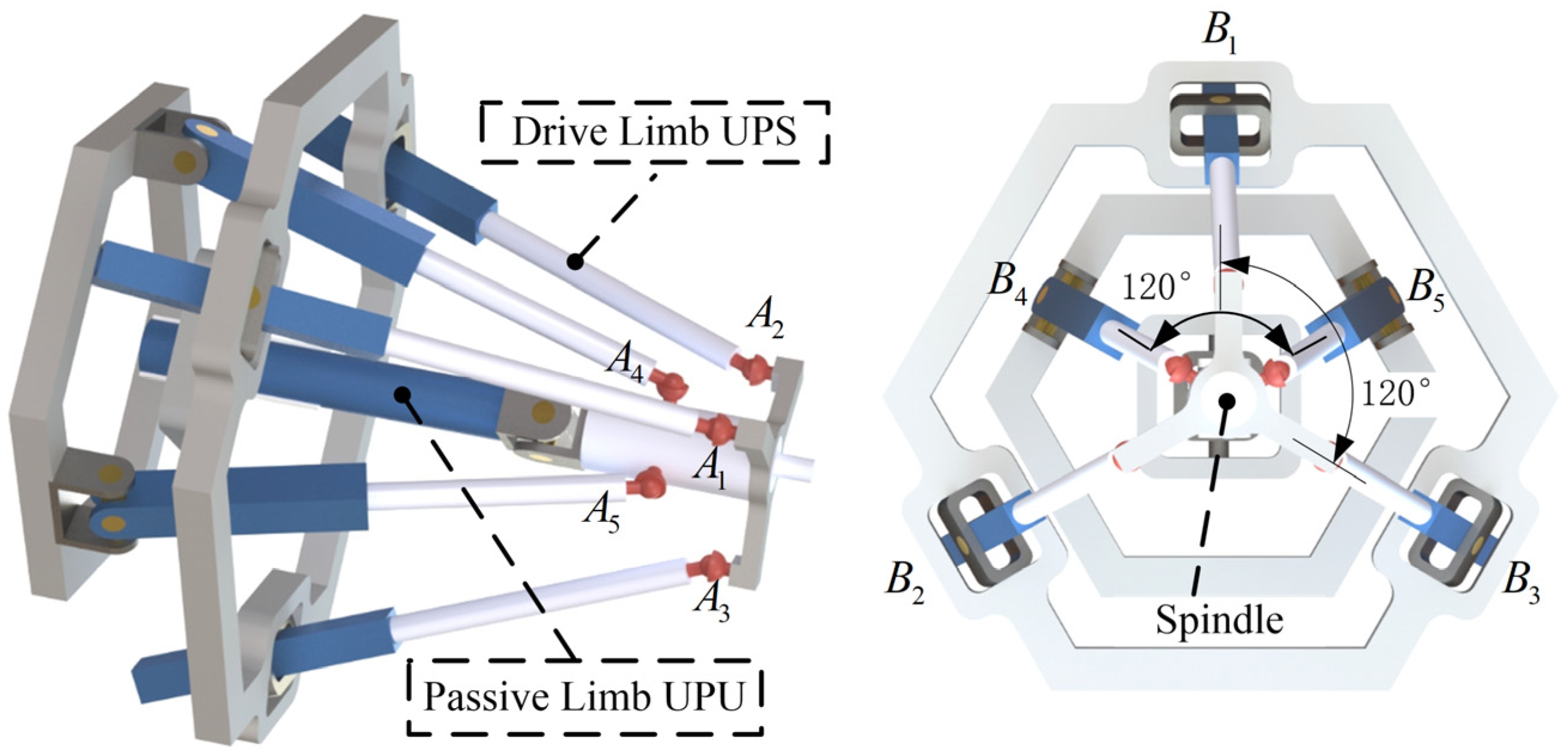
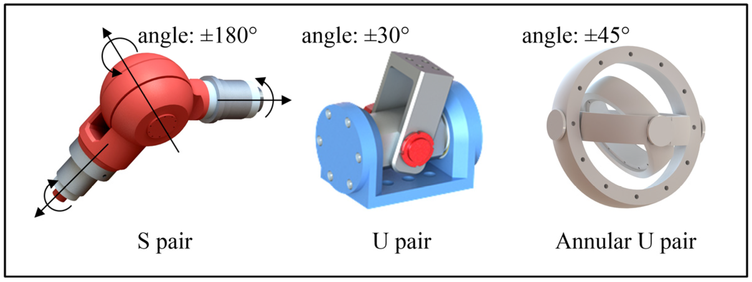
Therefore, the unconstrained limb can be synthesized into PPPS, PRPS, PUS, UPS, etc., and the constrained limb can be synthesized into UPU, PRPU, PPPU, etc. The sequence of motion pairs in each branch chain can be changed. Among them, P pair is divided into active and passive types, which is composed of a linear slide rail and a possible drive lead screw. It has the characteristics of high rigidity and large space proportion. The S pair, U pair and R pair are composed of bearings and shafts. They are small and difficult to drive, usually as passive joints. For the parallel 5-DOF machining robot, the force on each limb should be balanced and the volume should be small to avoid limb interference. The real accuracy, static, and dynamic performance of a robot is often affected by joint clearance, error, link flexibility, etc. The robot design should have the least possible number of joints and links. Therefore, the computer aided design model of the parallel robot discussed in this paper is shown in Figure 1. Its moving platform is connected to the base through six limbs. Five drive limbs are the same, and all of them are UPS limbs with P pair as the drive joint. The 6th limb is a completely passive UPU limb, which is installed at the symmetric center of the mechanism. The robot only has 12 joints and 6 links, which greatly guarantees the accuracy and dynamic performance.
From the perspective of force form, the five UPS limbs are driving limbs, and their driving forces are the axial tensile/compressive force of the lead screw. The UPU limb is a 3T2R passive limb, which provides a rotation constraint in the normal direction of the U pair, and its constraint force is an instantaneous wrench. The constrained limb is located at the symmetrical center of the robot and has the shortest length in geometry, which can provide excellent torsional strength. The stiffness design of the cylindrical passive constrained limb has also been well verified on existing robots such as Tricept and T5 [28]. Therefore, the topology design of the six-limb parallel machining robot discussed in this paper has mechanical rationality. At the same time, the U pair at the end of the UPU limb is located at the symmetrical center of the moving platform, and the A/B two-way rotation capability of the robot is relatively flexible.
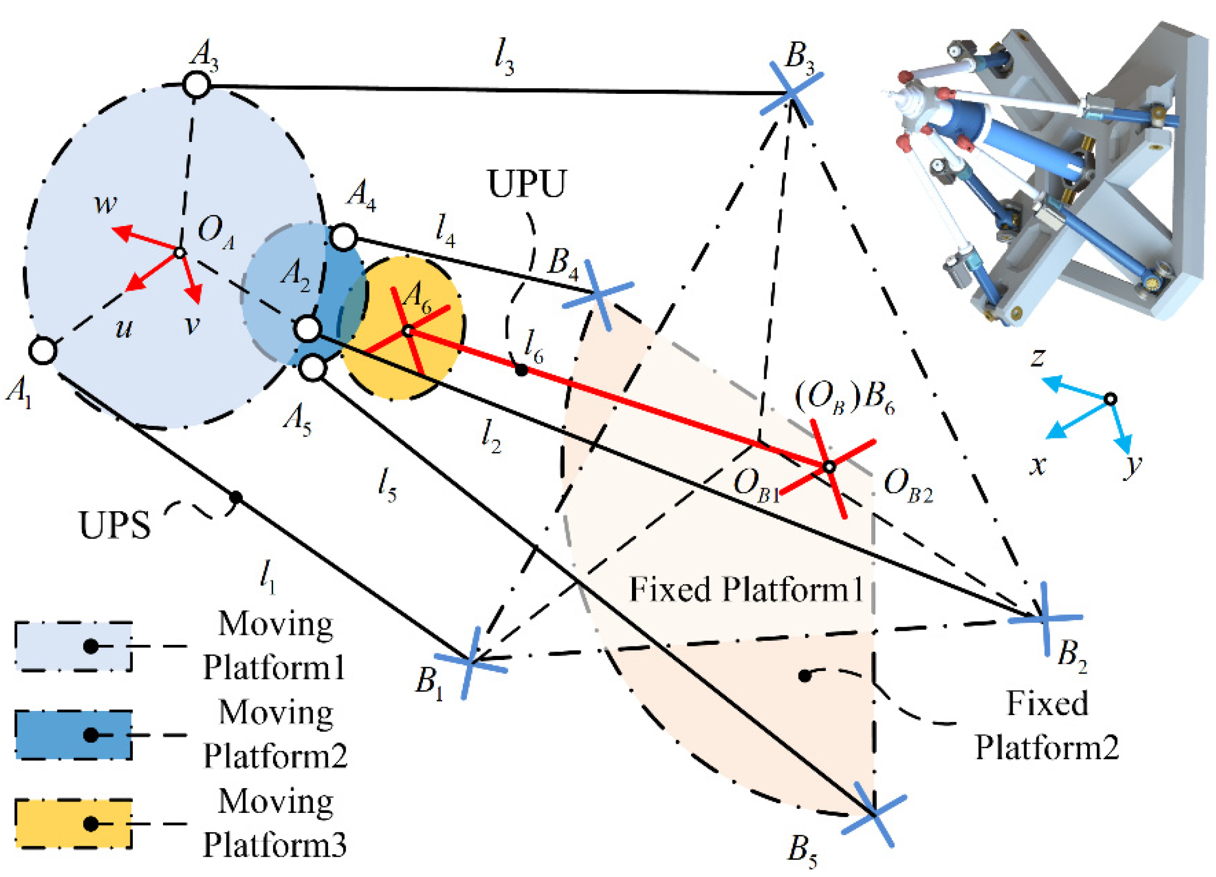
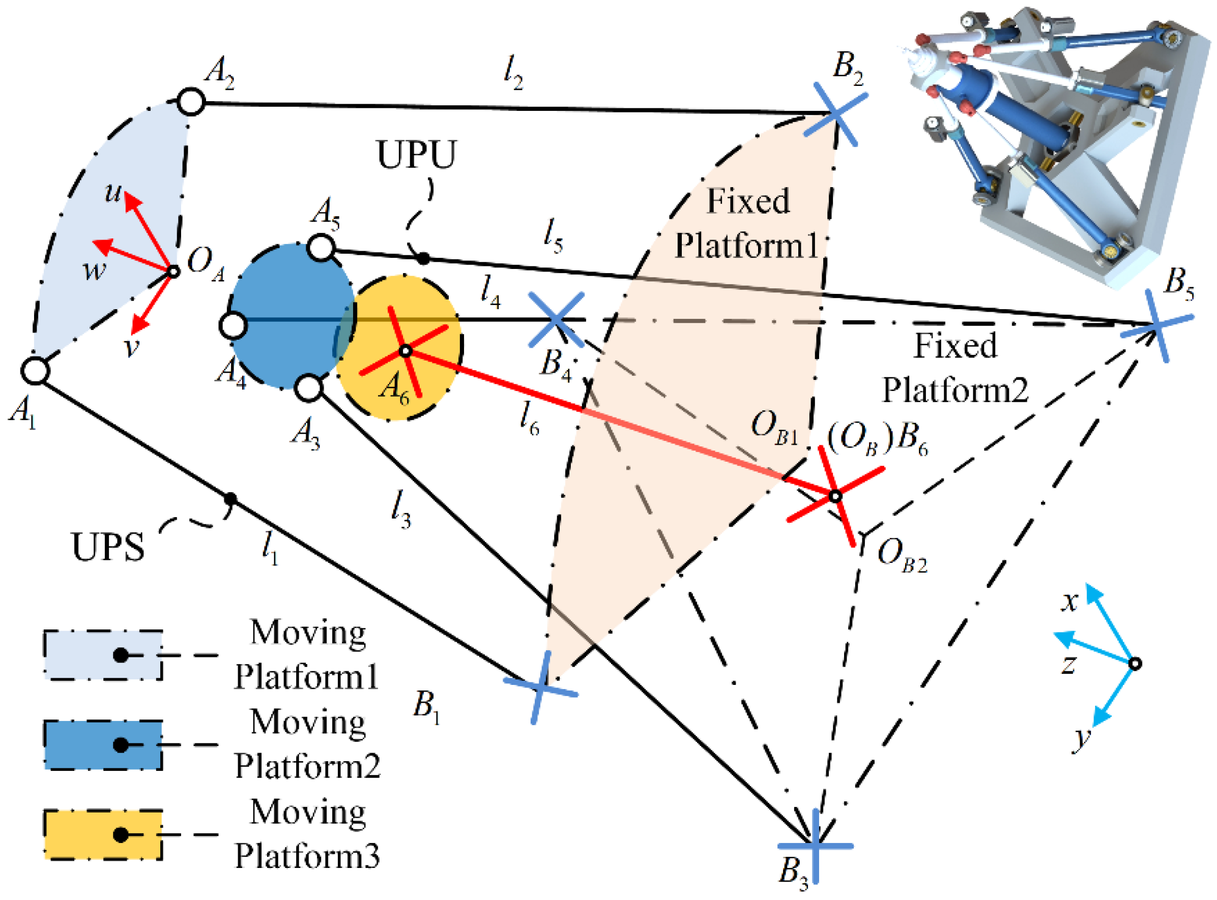
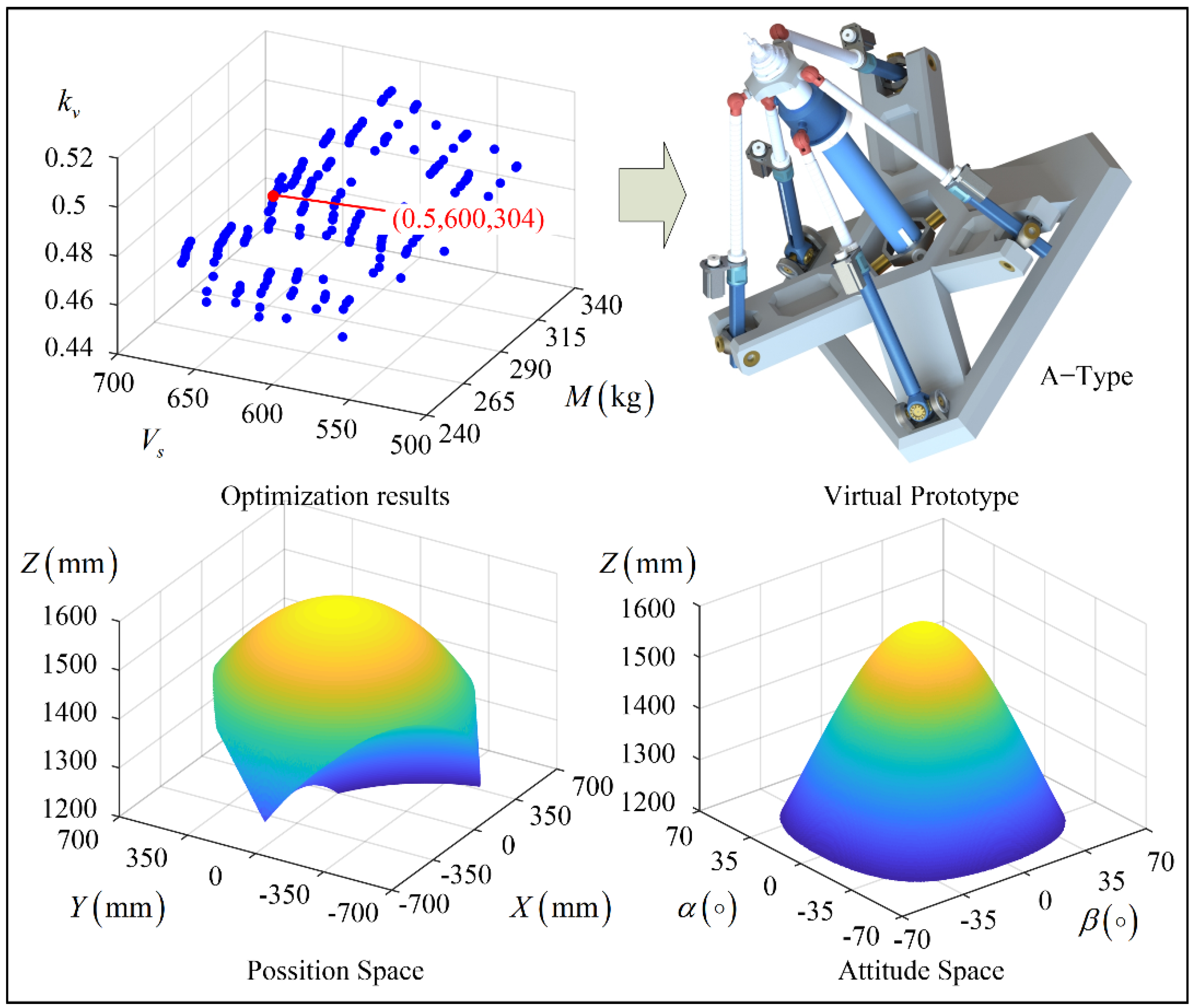
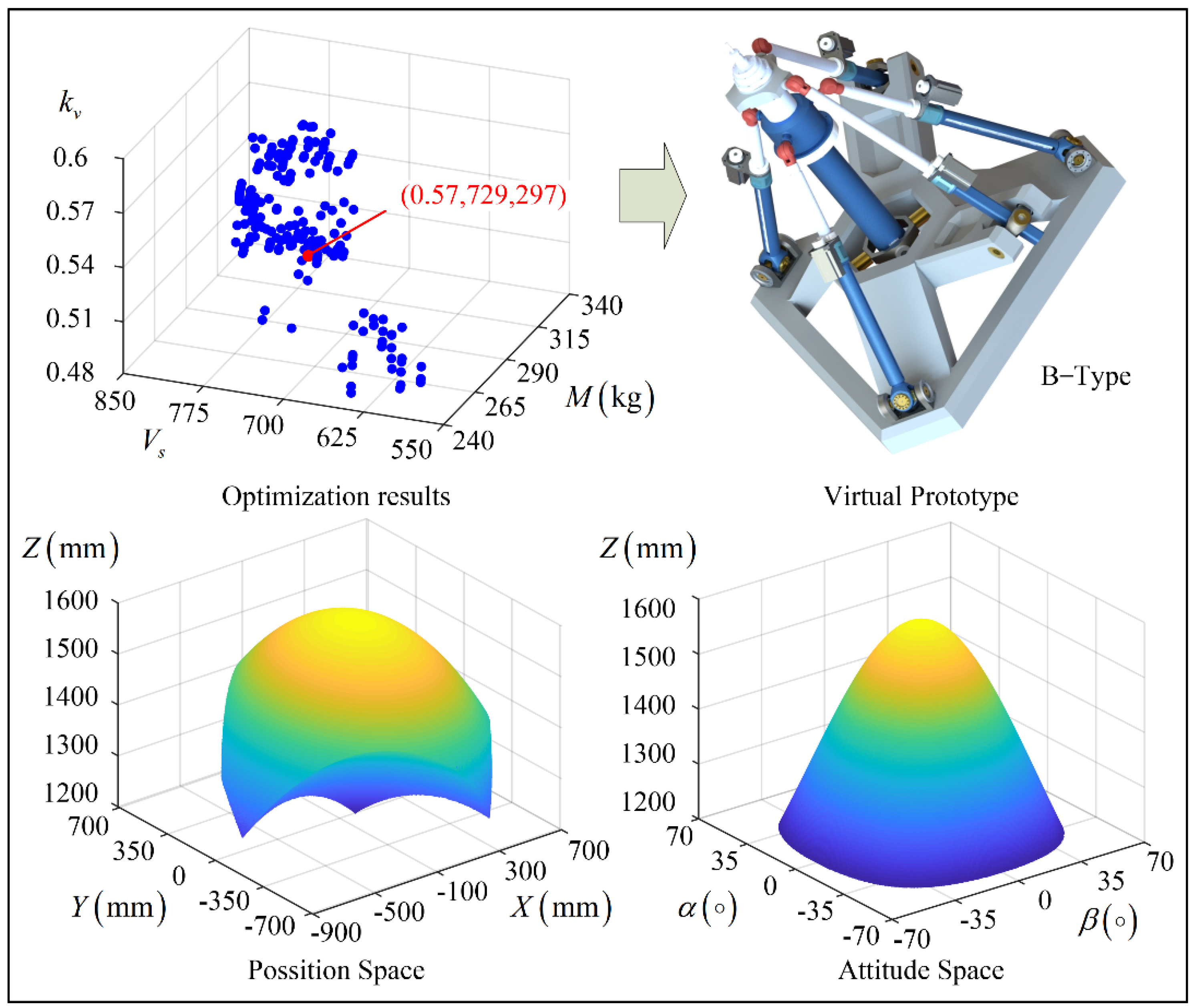
From the perspective of layout, the robot discussed in this paper has a spatial layout structure, and its moving and fixed platforms are divided into three layers. Moving platforms 1 and 2 are installed at the head and end of the motorized spindle, respectively. The distance between moving platform 3 and moving platform 2 is determined by the electrical circuit of the motorized spindle. Fixed platform 2 is the installation surface, and the three layers of fixed platforms together form a number of space triangle structures, which have mechanical stability. According to the different distribution modes of the hinge points of five UPS limbs on the multi-layer moving and fixed platforms, the robot discussed in this paper has two layout forms, A and B, as shown in Figure 2 and Figure 3, respectively. Among them, three UPS limbs of the A-type robot are connected to moving platform 1, and two UPS limbs are connected to moving platform 2. The type B robot is the opposite. The difference between the two layout forms leads to different contributions of each unconstrained limb to the overall position, rotation ability, and static performance of the robot, which is the focus of this paper.

3. Kinematic Model

3.1. Inverse Kinematics

As an example of the A-type mechanism diagram, the kinematics model of the robot is established in this section. As shown in Figure 2, A i ( i = 1 , 2 6 ) is the hinge point on moving platform 1~3, O A -uvw is the fixed coordinate system on the moving platform, and O A is the center of the triangle formed by points A 1 , A 2 , A 3 on moving platform 1. The direction of u-axis is parallel to O A A 1 , w-axis coincides with the axis of the spindle, and v-axis is determined by the right-hand rule. B i ( i = 1 , 2 6 ) is the center point of the U pair on the fixed platform, O B -xyz is the fixed coordinate system on the fixed platform. O B coincides with the center point B 6 of the U pair in the constraint limb UPU. Under the initial pose of the robot, all coordinate axes of the moving and fixed systems are parallel. l i ( i = 1 , 2 6 ) is the length of P pair.
In the fixed coordinate system, the position vectors of each hinge point of the fixed platform are:
{ B 1 = ( r 1 0 h 1 ) B 2 = ( r 1 sin θ 1 r 1 cos θ 1 h 1 ) B 3 = ( r 1 sin θ 1 r 1 cos θ 1 h 1 ) B 4 = ( r 2 sin θ 2 r 2 cos θ 2 h 2 ) B 5 = ( r 2 sin θ 2 r 2 cos θ 2 h 2 ) B 6 = ( 0 0 0 )
where r 1 and r 2 represent the radius of the circumscribed circle of the multi-layers fixed platforms, respectively. θ represents half of the included angle of the position vector in the fixed platform, in order to achieve central symmetry, θ = 60 . h 1 and h 2 represent the z-direction height difference between the multi-layers fixed platform.
In the moving coordinate system, the position vectors of each hinge point of the moving platform are:
{ A 1 = ( r 3 0 0 ) A 2 = ( r 3 sin θ 3 r 3 cos θ 3 0 ) A 3 = ( r 3 sin θ 3 r 3 cos θ 3 0 ) A 4 = ( r 4 sin θ 4 r 4 cos θ 4 h 4 ) A 5 = ( r 4 sin θ 4 r 4 cos θ 4 h 4 ) A 6 = ( 0 0 h 3 )
where r 3 and r 4 represent the radius of the circumscribed circle of the multi-layers moving platforms, respectively. θ 3 = θ 4 = 60 . h 3 and h 4 represent the z-direction height difference between the multi-layers moving platforms, respectively, and their dimensions are determined by the geometric dimensions of the spindle and its electrical cable layout.
From the above definition, the rotation matrix of system O A -uvw relative to system O B -xyz can be expressed as:
R = [ c γ c β c γ s β s α s γ c α c γ s β c α + s γ c α s γ c β s γ s β s α + c γ c α s γ s β c α c γ s α s β c β s α c β c α ]
where α , β , γ [ 0 , π ] represents the included angle of the axis of the moving and fixed coordinate systems. c and s represent cosine and sine, respectively.
The closed-loop vector equations is written as:
l i w i = r + R A i B i , ( i = 1 , 2 6 )
where r = ( x c y c z c ) T is the position vector of the point O A in the coordinate system O B x y z . w i is the direction vector of each link. According to Equation (11), the length of P pair can be solved as:
l i = ( r + R A i ) 2 ( B i ) 2
So far, the inverse kinematics solution of the robot has been completed. Similarly, the inverse position solution of robot with B-type layout can be obtained.

3.2. Workspace

Figure 4 shows several joint structures of the parallel 5-DOF machining robot discussed in this paper. As shown in Figure 4, the S pair of each UPS limb adopts three initial orthogonal R pairs, which is not limited by the rotation capacity. The rotation capacity of each static platform U is ±30°, and that of the moving platform U pair in the UPU limb is ±45°.
The angular limit of each joint can be obtained from the instantaneous angle between the P pair vector and the initial limit vector of the joint.
θ limit , i = arccos ( w i · s i | w i | | s i | ) θ max , i
The travel limit of the UPS connected to the fixed platform 2 is determined by the sleeve length. In addition, the lead screw of UPS connected to the fixed platform 1 can pass through the corresponding fixed platform plane, and its limit stroke is determined by the lead screw length.
l min , i l i l max , i
The interference problem of each limb can be simplified as the distance limitation D l , i of seven regular cylinders (six limbs + one spindle). So far, the robot constraint condition analysis is completed, and the constraint mathematical equation is:
{ l min , i < l i < l max , i θ l , i θ max , i D l , i > d i i = ( 1 , 2 , 6 )

3.3. Velocity and Force Model

The velocity of point O A can be calculated through the velocity of each limb by screw theory [29] as:
S t = S t , i = k = 1 6 S t , i , k = [ S ^ t , i , 1 S ^ t , i , 6 ] q ˙ i , ( i = 1 , 2 6 )
where S t , i , k represents the velocity of the kth joint in the ith limb, and S t , i , k is its unit instantaneous screw. q ˙ i represents the vector that contains all the angular and linear velocities of all the joints in the limb, and:
{ S ^ t , i , 1 = ( s u 1 , i ( A i l i w i ) × s u 1 , i ) , S ^ t , i , 2 = ( s u 2 , i ( A i l i w i ) × s u 2 , i ) , S ^ t , i , 3 = ( 0 w i ) , S ^ t , i , 4 = ( s s 1 , i A i × s s 1 , i ) , S ^ t , i , 5 = ( s s 2 , i A i × s s 2 , i ) , S ^ t , i , 6 = ( s s 3 , i A i × s s 3 , i ) , i = 1 , 2 5 S ^ t , 6 , 1 = ( s u 1 , i ( A i l i w i ) × s u 1 , i ) , S ^ t , 6 , 2 = ( s u 2 , i ( A i l i w i ) × s u 2 , i ) , S ^ t , 6 , 3 = ( 0 w i ) , S ^ t , 6 , 4 = ( s u 3 , i A i × s u 3 , i ) , S ^ t , 6 , 5 = ( s u 4 , i A i × s u 4 , i ) ,
where s u 1 , i , s u 2 , i represent the direction vectors of the two revolute joints of the fixed platform U joint in the ith limb. s u 3 , i , s u 4 , i represent the direction vectors of the two revolute joints of the moving platform U joint in the UPU limb. s s 1 , i , s s 2 , i , s s 3 , i represent the direction vectors of the three revolute joints of the S joint in the ith limb.
According to the reciprocal product principle between motion and constraint, the force screw of each limb can be obtained as:
S ^ w a , 1 = ( A i × w i w i ) , i = 1 , 2 5 , S ^ w c = ( n 0 )
where S w a , i and S w c represent the driving force screw and the constrained force screw, respectively. n is the normal direction of moving platform U pair in the UPU limb. Therefore, the wrench space of the robot is expressed as:
J w = [ S w a , 1 S w a , 2 S w a , 3 S w a , 4 S w a , 5 S w c ]
Let S ^ w be the unit actuation wrench of the ith limb. Taking the generalized inner product of Equation (16) with S ^ w , one can obtain:
S ^ w , i T S t = S ^ w , i T k = 1 6 q ˙ i , k S ^ t , i , k , i = 1 , 2 6
Equation (20) can be further written into matrix form as:
J w S t = J q q ˙
Therefore, the speed mapping of the 5UPS-UPU parallel machining robot can be written as:
S t = J w 1 J q q ˙ = J q ˙
where J is the Jacobian matrix.

4. Optimal Design

4.1. Optimization Index

The performance optimization design of robot is a typical multi-parameter, multi-objective and multi-constraint problem. For the parallel 5-DOF machining robot discussed in this paper, larger workspace, better kinematics performance, and lighter mass are the goals of its optimal design.
For the workspace of the robot, the maximum z direction operation capacity is determined by the limit travel of the P pair in the constrained limb UPU. In this paper, according to the requirements of engineering applications, it is given as 400 mm. Therefore, the square root of the maximum xy working capacity can be defined as the workspace index of the robot.
V s = x w y w
Kinematic performance of robot can be characterized by transmissibility [30]. By rewriting Equation (16), the twist of the robot can be expressed as:
S t = i = 1 6 ρ t , i ρ t , i ( S ^ w a , i , 1 T S ^ t , i , 1 ) S ^ t , i
where ρ t , i is the magnitude of S t , i . ρ t , i and S t , i are from
J w 1 = [ ρ t , 1 S ^ t , 1 ρ t , 2 S ^ t , 2 ρ t , 6 S ^ t , 6 ]
The instantaneous power of the robot is given as:
S w T S t = i = 1 6 f a , i , 1 ρ t , i ρ t , i ( S ^ w a , i , 1 T S ^ t , i ) ( S ^ w a , i , 1 T S ^ t , i , 1 )
where f a , i , 1 is the intensity of the actuation wrench.
The kinematics performance of the robot can be evaluated by the mean value of the minimum transmissibility in the whole workspace, which can represent the transfer efficiency of the robot motion/force.
k i = min { | S ^ w a , i T S ^ t a , i | | S ^ w a , i T S ^ t a , i | max , | S ^ w a , i T S ^ t a , i | | S ^ w a , i T S ^ t a , i | max } , i = 1 , 2 , 5
k v = w min ( μ i ) w
The design mass of the machining robot only considers the moving parts that contribute inertia. Therefore, the mass index of the robot is defined as follows:
M = i = 1 5 ( M U 1 + M P 1 + M S ) + ( M U 1 + M P 2 + M U 2 + M L ) + M m
where M m , M U , M S , M p and M L , represent the mass of the moving platform, U pairs, S pairs, P pairs, and links, respectively.

4.2. Optimization Models and Algorithm

Based on the above indicators and analysis, this paper establishes a multi-objective model with workspace, kinematic performance, and moving parts mass index as optimization objectives, and AB rotation ability, dimension parameter range, and maximum mass as constraints.
max { k v , V s } & min { M }   s . t . { M 400   kg R A B ± 40 x L x x U
For the problem described in Equation (30), NSGA-II algorithm [31] can be used for iterative solution according to our accumulated experience [32]. NSGA-II algorithm is one of the most popular multi-objective genetic algorithms. It reduces the complexity of non-inferior sorting genetic algorithms, and has the advantages of fast running speed and good convergence of the solution set. The settings of the algorithm are as follows: the initial parameters are determined by random functions, 40 populations are used, and the algorithm is run to 100 generations. The probabilities of crossover and mutation are 0.9 and 0.1, respectively. The crossover distribution and mutation distribution index are 10 and 20, respectively. The failed run penalty and objective value are 10 30 .
The Pareto frontier solution set obtained by multi-objective optimization can select the final result according to the cooperative equilibrium principle.
f i ( x ) = f i , j ( x ) κ f i σ f i
D c = τ = 1 3 ( f c , τ ( x ) f τ , min ) 2
where f i ( x ) is the ith target. κ f i and σ f i are the mean and variance of the target, respectively. f τ , min is the minimum point of the target, namely the virtual ideal point. D c is the distance from the Pareto frontier point to the ideal point. The point with the smallest D c value is the optimal solution with the best performance-matching relationship.

4.3. Optimization Parameters

According to Figure 2 and the previous analysis, the 5-DOF parallel machining robot discussed in this paper has the advantages of approximate center symmetry and flexible movement. The main dimension parameters include the radius of the circumscribed circle of the multi-layer moving and fixed platforms, the relative distance of the multi-layer fixed platforms, and the distance h of the moving and fixed platforms under the initial configuration.
The design range of each dimension parameter is shown in Table 1, where the radius of the fixed platform is 800 mm to 1200 mm, the radius of the moving platform is 150 mm to 300 mm, the distance of the multi-layer fixed platforms is –400 mm to 400 mm, and h is 1000 mm to 1400 mm. The minimum radius of the moving platform is determined by the outer diameter of the spindle and the structural size. The maximum radius of the fixed platform and the maximum distance between moving and fixed platforms are limited by volume. In addition, the maximum radius of the moving platform is limited by the mass of moving parts.

4.4. Optimization Result

With the help of MATLAB and Isight software, the optimization results for A and B type layout robots are carried out. The optimization results are shown in Figure 5 and Figure 6. Among them, the total number of solutions for the A-type robot is 4000, including 270 Pareto frontier solutions, and the total number of solutions for the B-type robot is 4000, including 246 Pareto frontier solutions.
The dimensionless method is then applied to the objectives on the Pareto frontier by Equation (29). The distance from Pareto points to the ideal optimum is calculated by Equation (30). The cooperative equilibrium point is determined as the Pareto point with minimal distance to the ideal point.
The values of k v , V s , M , and rotation ability for the A-type robot at cooperative equilibrium point are 0.5, 600, 304, and ±53°, respectively. The values of k v , V s , M , and rotation ability for the B-type robot at cooperative equilibrium point are 0.57, 729, 297, and ± 53°, respectively. Obviously, the performance of the B-type robot is better than that of the A-type robot.
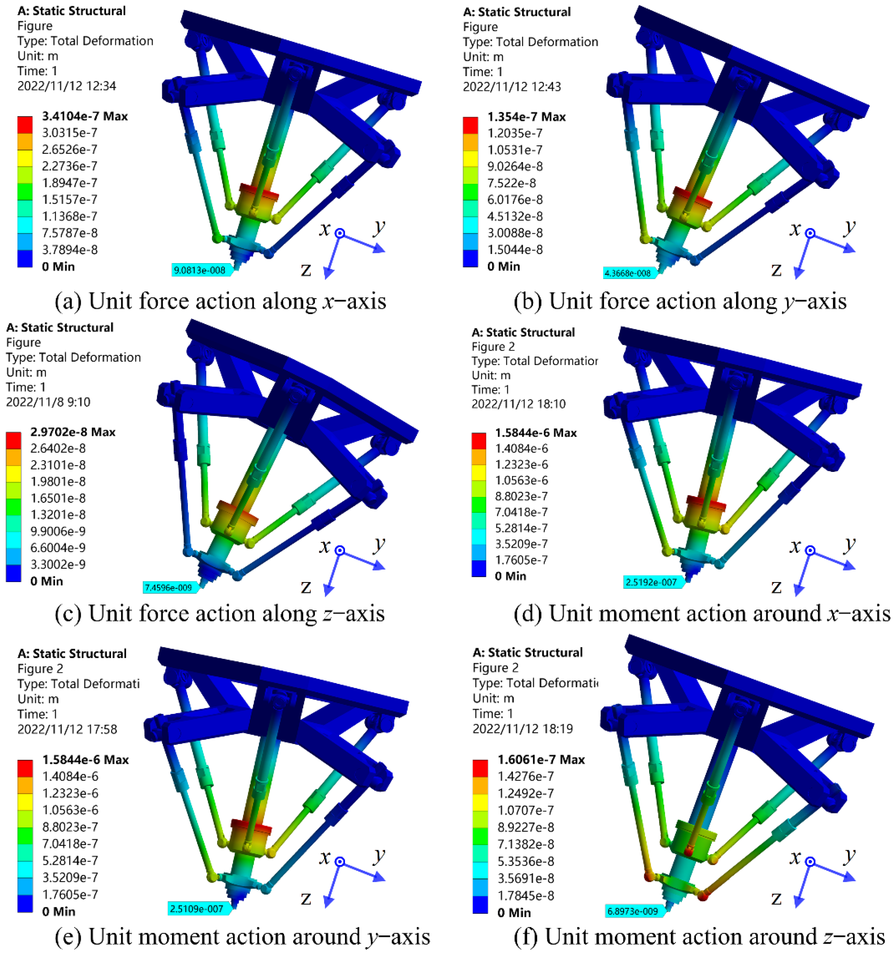
5. Simulation Verification

According to the previous analysis, the B-type robot has better kinematics performance and is the final output solution of optimal design. In this section, the static performance of the designed virtual prototype will be verified by computer simulation. The settings of the Ansys software are as follows:
(1)
Establish model: use SolidWorks to simplify the design of model structure, import the 3D model into ANSYS, define the material property as structural steel, and define the contact relationship between components according to the actual situation.
(2)
Grid generation: automatic grid generation is selected, with 883,175 nodes and 489,317 units in total.
(3)
Add boundary conditions: the bottom of the mobile platform is fixed to the ground, and a three-way unit force or moment is added at the tool center point.
(4)
Solution and post-processing: the total deformation of the system obtained by solution is shown in Figure 7.
The analysis results show that the maximum deformation of the robot occurs in the U pair connecting the constraint limb and the moving platform. The joint structure design of this part is the key to the performance design of this robot. The joint structure used in this paper has local defects, and the stiffness of the whole machine is expected to be significantly enhanced after improvement. However, the TCP line stiffness of the robot in all directions is still greater than 10 N / μ m , which meets the needs of actual machining. The robot designed in this paper still has excellent static performance and is suitable for efficient and high precision machining of complex curved components.

6. Conclusions

In this paper two novel parallel five degree of freedom (5-DOF) machining robots with spatial layout are proposed. This kind of robot has six motion limbs arranged in space, five of which are UPS limbs and one is a UPU limb. The robot is approximately centrally symmetric, with reasonable constraint and driving wrench design, and greatly releases the flexibility of the spindle. Kinematic optimization design of two robots is carried out by multi-objective optimization method and intelligent algorithm. The optimized design results show that the B-type layout has better kinematics performance. Lastly, the static performance of the optimal virtual prototype is verified by the finite element software. The numerical simulation demonstrates that the designed 5-DOF machining robot offers satisfactory static behavior and flexibility, which is of significant application value.
In the future, we will further optimize the weak rigid joint in the existing structures to develop engineering prototypes with better performance. Further, more topology types, layout forms, and performance indicators will be discussed.

Author Contributions

Conceptualization, K.C. and R.W.; methodology, R.W.; software, Z.N.; validation, K.C. and Z.N.; formal analysis, R.W.; resources, T.S.; data curation, Z.N.; writing—original draft preparation, R.W.; writing—review and editing, K.C.; project administration, K.C.; funding acquisition, T.S. All authors have read and agreed to the published version of the manuscript.

Funding

This research work was supported by the National Natural Science Foundation of China (NSFC) under Grant Nos. 62027812, 52275027, 52205028, State Key Laboratory of Digital Manufacturing Equipment and Technology under Grant No. DMETKF2022007.

Conflicts of Interest

No conflict of interest exists in the submission of this manuscript, and the manuscript is approved by all authors for publication.

Nomenclature

S f , M , S f , k , S f , k , i Screw description of mechanism, limb and kinematic pair
s a , s b , s c , s k , i , s i Axis vector of the kinematic pair
r a , r b , r c , r k , i , r i Position vector of kinematic pair
α , β Pitch angle (around A-axis) and roll angle (around B-axis)
θ i , θ k , i , t i , t k , i Angular and linear displacements
S t , S w Velocity and wrench

References

  1. Zhao, X.; Tao, B.; Ding, H. Multimobile Robot Cluster System for Robot Machining of Large-Scale Workpieces. IEEE/ASME Trans. Mechatron. 2021, 27, 561–571. [Google Scholar] [CrossRef]
  2. Zhu, D.; Feng, X.; Xu, X.; Yang, Z.; Li, W.; Yan, S.; Ding, H. Robotic grinding of complex components: A step towards efficient and intelligent machining—Challenges, solutions, and applications. Rob. Comput. Integr. Manuf. 2020, 65, 101908. [Google Scholar] [CrossRef]
  3. Chen, K.; Wang, M.; Huo, X.; Wang, P.; Sun, T. Topology and dimension synchronous optimization design of 5-DoF parallel robots for in-situ machining of large-scale steel components. Mech. Mach. Theory 2023, 179, 105105. [Google Scholar] [CrossRef]
  4. Zou, L.; Liu, X.; Ren, X.; Huang, Y. Investigation of robotic abrasive belt grinding methods used for precision machining of aluminum blades. Int. J. Adv. Manuf. Technol. 2020, 108, 3267–3278. [Google Scholar] [CrossRef]
  5. Almeida, S.; Mo, J.; Bil, C.; Ding, S.; Wang, X. Conceptual Design of a High-Speed Wire EDM Robotic End-Effector Based on a Systematic Review Followed by TRIZ. Machines 2021, 9, 132. [Google Scholar] [CrossRef]
  6. Ye, H.; Wang, D.; Wu, J.; Yue, Y.; Zhou, Y. Forward and inverse kinematics of a 5-DOF hybrid robot for composite material machining. Robot. Comput. Manuf. 2020, 65, 101961. [Google Scholar] [CrossRef]
  7. Xin, S.; Peng, F.; Tang, X.; Yan, R.; Li, Z.; Wu, J. Research on the influence of robot structural mode on regenerative chatter in milling and analysis of stability boundary improvement domain. Int. J. Mach. Tools Manuf. 2022, 179, 103918. [Google Scholar] [CrossRef]
  8. Tao, B.; Zhao, X.; Ding, H. Mobile-robotic machining for large complex components: A review study. Sci. China Technol. Sci. 2019, 62, 1388–1400. [Google Scholar] [CrossRef]
  9. Bu, Y.; Liao, W.; Tian, W.; Zhang, L.; Dawei, L. Modeling and experimental investigation of Cartesian compliance characterization for drilling robot. Int. J. Adv. Manuf. Technol. 2017, 91, 3253–3264. [Google Scholar] [CrossRef]
  10. Meng, S.; Liu, H.; Xiao, J.; Huang, T.; Ni, Y.; Sun, S. A method for process parameter optimization of simultaneous double-sided friction stir welding using a heat transfer model. Int. J. Adv. Manuf. Technol. 2022, 121, 3747–3758. [Google Scholar] [CrossRef]
  11. Siciliano, B.; Khatib, O. Springer Handbook of Robotics, 2nd ed.; Springer: Cham, Switzerland, 2016. [Google Scholar]
  12. Merlet, J.P. Parallel Robots, 2nd ed.; Springer: Dordrecht, The Netherlands, 2006. [Google Scholar]
  13. Chablat, D.; Wenger, P. Architecture optimization of a 3-DOF translational parallel mechanism for machining applications, the orthoglide. IEEE Trans. Robot. Autom. 2003, 19, 403–410. [Google Scholar] [CrossRef] [Green Version]
  14. Shi, J.; Wang, Y.; Zhang, G.; Ding, H. Optimal design of 3-DOF PKM module for friction stir welding. Int. J. Adv. Manuf. Technol. 2012, 66, 1879–1889. [Google Scholar] [CrossRef]
  15. Dong, C.; Liu, H.; Huang, T.; Chetwynd, D.G. A Screw Theory-Based Semi-Analytical Approach for Elastodynamics of the Tricept Robot. J. Mech. Robot. 2019, 11, 1–20. [Google Scholar] [CrossRef]
  16. Hu, B. Kinematically identical manipulators for the Exechon parallel manipulator and their comparison study. Mech. Mach. Theory 2016, 103, 117–137. [Google Scholar] [CrossRef]
  17. Dong, C.; Liu, H.; Yue, W.; Huang, T. Stiffness modeling and analysis of a novel 5-DOF hybrid robot. Mech. Mach. Theory 2018, 125, 80–93. [Google Scholar] [CrossRef] [Green Version]
  18. Xie, F.; Liu, X.-J.; Luo, X.; Wabner, M. Mobility, Singularity, and Kinematics Analyses of a Novel Spatial Parallel Mechanism. J. Mech. Robot. 2016, 8, 061022. [Google Scholar] [CrossRef]
  19. Xie, Z.; Xie, F.; Liu, X.-J.; Wang, J.; Mei, B. Tracking error prediction informed motion control of a parallel machine tool for high-performance machining. Int. J. Mach. Tools Manuf. 2021, 164, 103714. [Google Scholar] [CrossRef]
  20. Tunc, L.T.; Shaw, J. Experimental study on investigation of dynamics of hexapod robot for mobile machining. Int. J. Adv. Manuf. Technol. 2016, 84, 817–830. [Google Scholar] [CrossRef]
  21. Wang, C.; Fang, Y.; Guo, S. Design and Analysis of 3R2T and 3R3T Parallel Mechanisms With High Rotational Capability. J. Mech. Robot. 2015, 8, 011004. [Google Scholar] [CrossRef]
  22. Bi, W.; Xie, F.; Liu, X.-J.; Luo, X. Optimal design of a novel 4-degree-of-freedom parallel mechanism with flexible orientation capability. Proc. Inst. Mech. Eng. Part B J. Eng. Manuf. 2017, 233, 632–642. [Google Scholar] [CrossRef]
  23. Brahmia, A.; Kelaiaia, R.; Chemori, A.; Company, O. On Robust Mechanical Design of a PAR2 Delta-Like Parallel Kinematic Manipulator. J. Mech. Robot. 2022, 14, 011001. [Google Scholar] [CrossRef]
  24. Xu, L.; Chen, G.; Ye, W.; Li, Q. Design, analysis and optimization of Hex4, a new 2R1T overconstrained parallel manipulator with actuation redundancy. Robotica 2019, 37, 358–377. [Google Scholar] [CrossRef]
  25. Xie, F.; Liu, X.-J.; Wang, J.; Wabner, M. Kinematic Optimization of a Five Degrees-of-Freedom Spatial Parallel Mechanism With Large Orientational Workspace. J. Mech. Robot. 2017, 9, 051005. [Google Scholar] [CrossRef]
  26. Yao, J.; Gu, W.; Feng, Z.; Chen, L.; Xu, Y.; Zhao, Y. Dynamic analysis and driving force optimization of a 5-DOF parallel manipulator with redundant actuation. Robot. Comput. Manuf. 2017, 48, 51–58. [Google Scholar] [CrossRef]
  27. Sun, T.; Yang, S.; Lian, B.T. Finite and Instantaneous Screw Theory in Robotic Mechanism; Springer: Singapore, 2020; pp. 40–47. [Google Scholar]
  28. Lian, B.; Sun, T.; Song, Y.; Jin, Y.; Price, M. Stiffness analysis and experiment of a novel 5-DoF parallel kinematic machine considering gravitational effects. Int. J. Mach. Tools Manuf. 2015, 95, 82–96. [Google Scholar] [CrossRef] [Green Version]
  29. Qi, Y.; Sun, T.; Song, Y. Type Synthesis of Parallel Tracking Mechanism With Varied Axes by Modeling Its Finite Motions Algebraically. J. Mech. Robot. 2017, 9, 054504. [Google Scholar] [CrossRef]
  30. Liu, X.-J.; Chen, X.; Nahon, M. Motion/Force Constrainability Analysis of Lower-Mobility Parallel Manipulators. J. Mech. Robot. 2014, 6, 031006. [Google Scholar] [CrossRef]
  31. Deb, K.; Pratap, A.; Agarwal, S.; Meyarivan, T. A fast and elitist multiobjective genetic algorithm: NSGA-II. IEEE Trans. Evol. Comput. 2002, 6, 182–197. [Google Scholar] [CrossRef] [Green Version]
  32. Song, Y.; Lian, B.; Sun, T.; Dong, G.; Qi, Y.; Gao, H. A Novel Five-Degree-of-Freedom Parallel Manipulator and Its Kinematic Optimization. J. Mech. Robot. 2014, 6, 041008. [Google Scholar] [CrossRef]
Figure 1. Integrated optimization design method.
Machines 10 01187 g001
Figure 2. A−type mechanism diagram.
Machines 10 01187 g002
Figure 3. B−type mechanism diagram.
Machines 10 01187 g003
Figure 4. Joint structure.
Machines 10 01187 g004
Figure 5. Result A.
Figure 5. Result A.
Machines 10 01187 g005
Figure 6. Result B.
Figure 6. Result B.
Machines 10 01187 g006
Figure 7. Simulation verification.
Machines 10 01187 g007
Table 1. Dimension parameter range.
r 1 r 2 r 3 r 4 h 1 h 2 h
800–1300800–1300150–300150–300−400–400−400–4001000–1400
Publisher’s Note: MDPI stays neutral with regard to jurisdictional claims in published maps and institutional affiliations.

