1. Introduction
Gear faults such as crack, pitting and spalling occur frequently because of some possible factors such as manufacturing defects, machining errors and harsh operating environment. These gear faults may induce undesirable vibration behaviors, influence dynamic transmission performances, reduce its fatigue life, and even result in safety accidents. For the purpose of detecting gear damages and giving an early warning, vibration analysis is widely considered as an effective condition monitoring tool of gear transmissions [
1,
2].
The planetary gear system is a kind of commonly used transmission device of vehicles, ships, aircrafts, wind turbines and so on. However, due to the high-load working condition and the large transmission ratio, tooth crack may initiate at the stress concentration region and propagate during operation, which is one of the most frequent failure modes of planetary gear systems. The presence and propagation of tooth crack leads to the reduction of the gear mesh stiffness and causes excessive mesh impacts in the vibration responses [
3]. In order to reveal the vibration characteristics and fault mechanism, plenty of efforts have been devoted to the dynamic modeling and vibration analysis of cracked planetary gear systems.
Time-varying mesh stiffness (TVMS) is the main internal excitation that affects gear vibration behaviors. Tooth crack propagation could reduce the TVMS, and in turn, TVMS can be utilized to assess the status of tooth crack. The TVMS evaluation methods for gear fault diagnosis mainly include the square waveform method, finite element method and potential energy method. Some studies assumed the TVMS as a square waveform, and the tooth fault can be considered as the reduction of square waveform amplitude [
4,
5,
6,
7]. As the square waveform can be approximated using Fourier Series, a number of investigations also applied the first several terms of Fourier Series to express TVMS [
8,
9]. However, the square waveform method ignores the TVMS change of tooth contact position, which is not accurate enough and has been seldomly used in recent studies. The finite element method is a powerful tool to evaluate TVMS accurately for different gear types, even for some special gears with complicated structures. Some studies have adopted the finite element method to obtain TVMS for the planetary gear systems [
10,
11], while other studies have applied the finite element method to validate the TVMS obtained by other methods [
12,
13,
14,
15]. However, owing to the mesh refinement and contact analysis, the finite element method is always time-consuming and requires a large amount of computational cost. The potential energy method is an analytical method that can give mathematical expressions of TVMS explicitly. In this method, the total energy stored in a gear pair is assumed to be the sum of several subitems such as bending energy, shearing energy, axial compressive energy, Hertzian contact energy and so on. Corresponding stiffness of each subitem can be derived explicitly based on the beam theory. The potential energy method shows the same accuracy but needs very low computational cost compared to the finite element method. Thus, it has been extensively developed to evaluate different faults for different gear types, and relevant studies have been reviewed by Liang et al. [
3] and Ma et al. [
16]. In the planetary gear systems, the potential energy method is successfully applied to determine the TVMS and is then combined with the dynamic model to achieve vibration analysis and fault simulation for tooth crack conditions. By improving the potential energy method, Chen et al. carried out a series of studies on a cracked single-stage planetary gear set considering different crack sizes and inclination angles [
17], the ring gear crack [
18], tooth plastic inclination deformation [
19] and flexible ring gear rim [
20]. Liang et al. [
21] modified the cantilever beam model for cracked tooth and proposed a comprehensive TVMS calculation method for a planetary gear set. Based on this model, the influence of the transmission path and a vibration signal decomposition method were further analyzed in their work [
22,
23]. Li et al. [
24,
25] established a coupled lateral-torsional dynamic model for a complicated two-stage compound planetary gear set and analyzed the effect of damaged planet gear on the fault properties. Chen et al. [
26] considered the bearing clearance and the sun gear crack simultaneously in a wind turbine planetary gear set. Jiang et al. [
27] investigated vibration fault features of a planetary gear train based on a lumped parameter model of z gear train and a finite element model of flexible housing. Based on the nonlinear dynamic model and the potential energy method, some studies focused on the influences of a tooth crack on the nonlinear vibration characteristics and chaotic motions of a planetary gear system [
28,
29]. Considering the crack closure effect, Duan et al. [
30] investigated the crack propagation path and TVMS based on a three-dimensional numerical model of a planetary gear train. Han et al. [
31] improved a lumped parameter dynamic model of a planetary gear set that considered the time varying distance between the planet gear and the transducer mounted on the fixed ring gear. Hu et al. [
32] considered several nonlinear factors in a 21 degrees of freedom (DOF) translation-torsional model for a helicopter planetary gear set and investigated the effects of tooth crack on the nonlinear vibration behaviors.
From the literature review above, numerous investigations have been conducted on the dynamic modeling and analysis of the planetary gear system with a tooth crack defect. Most of existing studies on the cracked planetary gear system assumed that the tooth crack propagated through the whole tooth width with a constant crack depth, as shown in
Figure 1a. This kind of crack is named as the plane uniform crack here, as it propagates in a plane with a uniform distribution along the tooth width. Differently, Chen and Shao [
33] pointed out that a tooth crack started from a stress concentration position and propagated non-uniformly along the tooth width. They proposed a plane non-uniform crack as shown in
Figure 1b, which could be more reasonable than the uniform crack and has been adopted by many investigations. However, both crack types in
Figure 1a,b are oversimplified from actual cracks. In the proposed tooth model, a tooth crack propagates not only along the crack depth direction and the tooth width direction, but also along the tooth height direction, which is closer to actual cracks. The tooth crack surface is always a spatial surface rather than a plane, as shown in
Figure 1c. Thus, a gear dynamic model with a spatial crack could be closer to actual applications. As a spatial crack distributes in the three-dimensional space, the TVMS calculation of a spatial crack needs a systematic model that considers the crack depth, angle, length and height simultaneously. A number of studies paid attention to the modeling and TVMS calculation of spatial tooth crack [
34,
35,
36]. However, previous studies have mainly concentrated on the effects of spatial crack shape on the TVMS, while the calculation process considering the crack depth, angle, length and height was only simply introduced. Furthermore, the spatial crack model has not yet been coupled with a dynamic model to analyze their combined effect on the vibration characteristics of a planetary gear system. Thus, there is still a lack of a comprehensive study on the systematic TVMS method and vibration characteristics of the planetary gear system with a spatial tooth crack.
Therefore, this study focuses on the improved TVMS method of the spatial tooth crack and vibration characteristics of the planetary gear system. Firstly, a systematic spatial tooth crack model is proposed considering the crack depth, angle, length and height simultaneously. Detailed mathematical expressions of mesh stiffness under different crack conditions are derived. Then, a coupled translational-torsional dynamic model is established for a planetary gear system including time-varying parameters and nonlinear factors. Simulated vibration responses are analyzed in the time domain and frequency domain to assess the health conditions of the planetary gear system.
2. Improved TVMS Method of a Spatial Cracked Gear
In this section, an improved TVMS calculation method is proposed for a spatial spur gear tooth. Firstly, the TVMS calculation method of a healthy tooth model is obtained as a basis of the cracked tooth model. Secondly, a tooth model with a plane uniform crack is established considering the crack depth, angle, width and height simultaneously, as it is the basis of the spatial crack model. Finally, the TVMS calculation method of a spatial cracked tooth is determined.
2.1. TVMS Method of a Healthy Gear
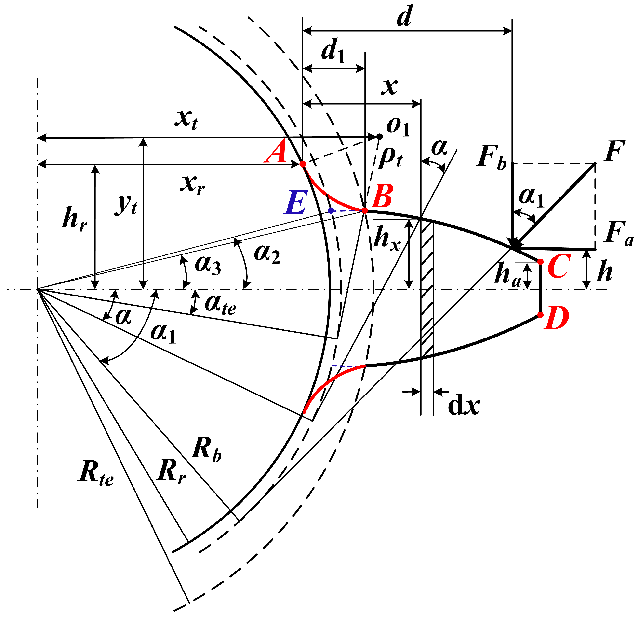
For a healthy spur gear, the tooth model can be simplified as a non-uniform cantilever beam as shown in
Figure 2. It is assumed that the tooth profile is generated by a double rounded rack. Thus, the tooth profile contains three parts: the transition curve
AB, the involute curve
BC and the addendum curve
CD. Three important circles should be mentioned: the root circle with a radius
Rr, the base circle with a radius
Rb, and the “transition end circle” with a radius
Rte. The circle passing through point
B is defined as “transition end circle”, as
B is the end point of the transition curve
AB. Point
E is the intersection point of the involute curve and the base circle. In some early studies, the transition end circle is assumed to be the same as the base circle, and point
E and point
B are considered the same point. However, points
E and
B come in superposition only if the gear is considered at the limit of the undercut. In actual spur gears, these two circles are always different. For example, when a profile shifting is given, the transition end circle radius is greater than the base circle radius. In this study, the transition curve is approximated as a circular arc with a radius of 𝜌
t determined by,
where
m is the module,
α0 is the pressure angle, and the
c* is the tip clearance coefficient.
According to the potential energy method, the total mesh stiffness of a healthy tooth pair consists of bending stiffness kb, shear stiffness ks, axial compressive stiffness ka, Hertzian contact stiffness kh and fillet-foundation stiffness kf.
2.1.1. Bending, Shear and Axial Compressive Stiffness
Based on the beam theory,
kb,
ka,
ks can be expressed as [
33,
37,
38,
39],
where
Some key parameters (including
xt,
yt,
hte,
Rte,
αte and
α3) on the transition curve in
Figure 2 can be determined by solving the following equations simultaneously,
Substituting Equations (5)–(9) into Equations (2)–(4), the equations of
kb,
ka,
ks for a healthy gear tooth can be obtained as:
where
v is Poisson’s ratio.
2.1.2. Hertzian Contact Stiffness
The Hertzian contact stiffness
kh of the tooth pair in contact can be determined by [
39,
40,
41],
where
Ftotal is the total meshing force,
Fi is the meshing force of the
ith tooth pair in contact,
LSRi is the load share ratio of the
ith tooth pair.
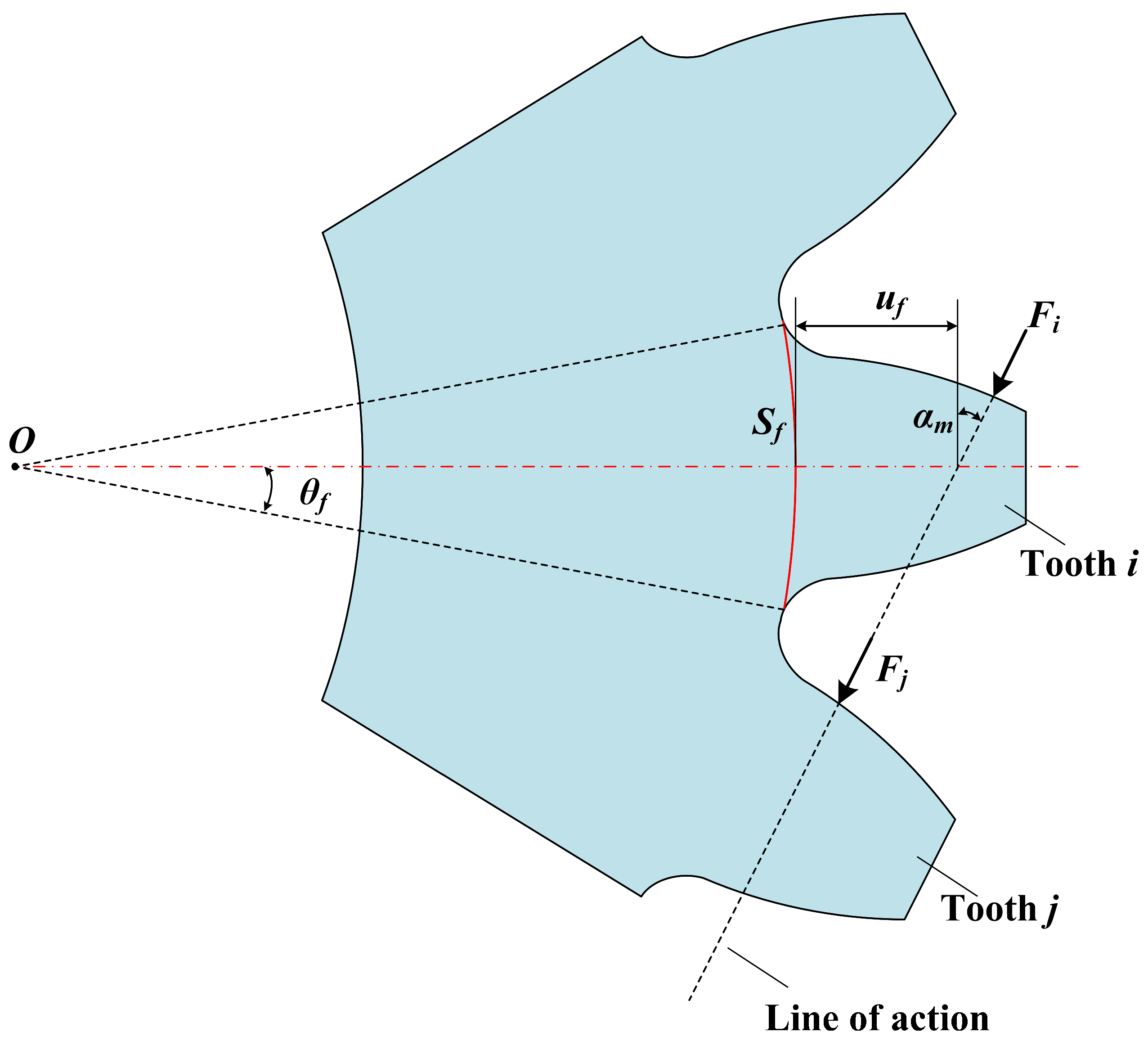
2.1.3. Fillet-Foundation Stiffness
The fillet-foundation stiffness of a gear pair should be determined according to the number of tooth pair in contact. In the single tooth engagement region, only one tooth pair is in contact, and the analytical expression of fillet-foundation deflection proposed by Sainsot et al. [
42] was extensively applied to calculate the fillet-foundation stiffness
kf,
where
αm,
uf,
Sf can be found in
Figure 3. The coefficients
L*,
M*,
P*,
Q* can be found in Ref. [
42].
2.1.4. Gear Body Structure Coupling Deflection
As can be seen in
Figure 3, the force
Fi applied at tooth
i not only makes tooth
i deformed but also influences the adjacent tooth
j through the gear body structure, and vice versa. This effect is defined as the gear body structure coupling effect, which could affect the total mesh stiffness in the double tooth engagement region. It has attracted the attention of some researchers, such as Ma et al. [
43], Xie et al. [
44], Chen et al. [
45] and so on. In this study, the gear body structure coupling effect is also considered, and the analytical formulas proposed by Xie et al. [
44] are adopted.
In the double tooth engagement region, the fillet-foundation stiffness should be calculated considering the gear body structure coupling deflection:
where 𝛿
f,ii is the tooth deflection of tooth
i contributed by
Fi; 𝛿
f,jj is the tooth deflection of tooth
j contributed by
Fj. They are also defined as the local gear body-induced tooth deflections. 𝛿
f,ij is the gear body structure coupling deflection of tooth
i contributed by
Fj; 𝛿
f,ji is the gear body structure coupling deflection of tooth
j contributed by
Fi. They are also defined as the structure coupling gear body-induced tooth deflections. The expressions of 𝛿
f,ii (or 𝛿
f,jj), 𝛿
f,ij and 𝛿
f,ji can be found in Xie et al. [
44].
2.1.5. Overall Mesh Stiffness
As the fillet-foundation stiffness in the single tooth engagement region is different with that in the double tooth engagement region, the calculation methods of overall mesh stiffness for these two regions are also different.
In the single tooth engagement region, the overall mesh stiffness can be calculated according to the following formula:
where subscripts 1 and 2 denote gear 1 and gear 2, respectively.
In the double tooth engagement region, the overall mesh stiffness can be calculated according to the following formula [
44]:
where
kh is the Hertzian contact stiffness, the subscripts
i and
j represent the
ith tooth and
jth tooth, respectively, and the superscripts
m = 1 and 2 represent gear 1 and gear 2. respectively.
and
are the tooth mesh stiffness of tooth
i and tooth
j, respectively.
2.2. TVMS Method of a Gear Tooth with a Plane Uniform Crack
A tooth crack reduces the load capacity of the tooth and decreases the amplitude of mesh stiffness. The overall mesh stiffness of a cracked tooth still consists of above five subitems of stiffness. The axial compressive stiffness of a cracked tooth is assumed to be the same as that of a healthy tooth, as the cracked part can still bear the axial compressive force. The Hertzian contact stiffness is affected by the tooth crack, but its analytical formula remains the same as shown in Equation (19), which will not be repeated in the section. The effects of the tooth crack on the fillet-foundation stiffness have also attracted the attention of several researchers, such as Jiang and Liu [
46], Chen et al. [
47], Yang et al. [
48,
49] and so on. In this study, the fillet-foundation stiffness of a cracked spur gear is obtained by using the model from Yang et al. [
48], as their model considered both tooth and rim cracks. Thus, in the following content, the analytical expressions of bending and shear stiffness are derived and emphasized.
As mentioned above, a tooth model should be established considering the crack depth, angle, length and height simultaneously. The crack initial position changes with the crack height. The geometric parameters on the tooth root fillet and those on the involute curve are different. Thus, considering different crack heights, two types of cracks should be considered: (1) the crack starts on the root fillet, and (2) the crack starts on the involute part.
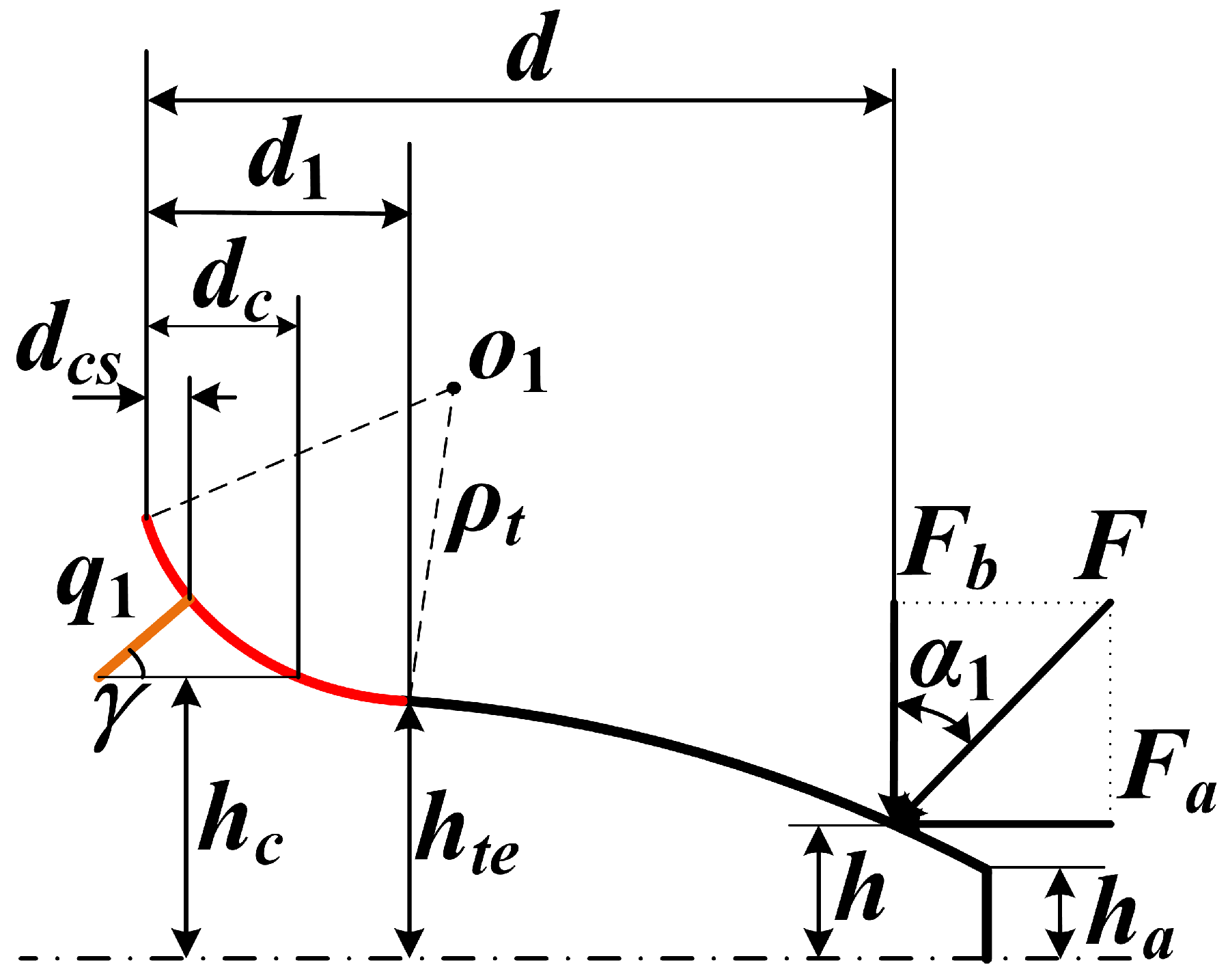
2.2.1. The Crack Occurs on the Root Fillet (Rcs < Rte)
As shown in
Figure 4, the straight line
FG denotes the tooth crack. Point
F is the crack start point.
Rcs is the radius of the circle passing through point
F.
Rte is the radius of the transition end circle passing through the end point
B of transition curve
AB. Apparently,
Rcs <
Rte means that the tooth crack occurs on the root fillet
AB, while
Rcs >
Rte means that the tooth crack occurs on the involute curve
BC.
q1 and
γ represent the crack depth and angle, respectively.
From the geometric relationship shown in
Figure 4, the coordinate of point
F (
xcs,
hcs) can be determined by solving:
Some key geometric parameters then can be obtained as:
In order to predict TVMS for any reasonable crack lengths and crack angles, several cases and several conditions should be considered and analyzed as follows.
Case 1: dcs < q1cosγ
- (1)
Condition 1: hte > hc > ha and α1 > αc
As shown in
Figure 4,
hte represents half of the chordal tooth thickness at point
B,
hc represents the distance from the crack end point
G to the tooth central line, and
ha represents half of the chordal tooth thickness at the tooth addendum. The section area and the area moment of inertia of the cracked tooth can be calculated as:
where
hx is determined by Equation (8).
Substituting Equations (8) and (27)–(29) into Equations (2) and (3), the bending and shear stiffness can be derived as:
- (2)
Condition 2: hc < ha or hte > hc > ha and α1 < αc
The section area and the area moment of inertia of the cracked tooth can be calculated as:
Substituting Equations (8), (27), (32) and (33) into Equations (2) and (3), the bending and shear stiffness can be derived as:
- (3)
Condition 3: hc > hte
In the early stage of the crack propagation,
hc may be larger than
hte, as shown in
Figure 5.
The section area and the area moment of inertia of the cracked tooth are the same as those in Equations (28) and (29), but the parameter
dc is different, which can be obtained by solving the following equations:
Substituting Equations (8) and (27)–(29) into Equations (2) and (3), the bending and shear stiffness can be derived as:
Case 2: dcs > q1cosγ
- (1)
Condition 1: hte > hc > ha and α1 > αc
At this circumstance, the section area and the area moment of inertia of the cracked tooth can be calculated as:
Substituting Equations (8), (27), (40) and (41) into Equations (2) and (3), the bending and shear stiffness can be derived as:
- (2)
Condition 2: hc < ha or hte > hc > ha and α1 < αc
The section area and the area moment of inertia of the cracked tooth can be expressed as:
Substituting Equations (8), (27), (44) and (45) into Equations (2) and (3), the bending and shear stiffness can be derived as:
- (3)
Condition 3: hc > hte
The expressions of
Ax and
Ix are the same as those in Equations (40) and (41), and
dc in
Figure 5 can also be calculated by Equations (36) and (37). The bending and shear stiffness can be derived as:
2.2.2. The Crack Occurs on the Involute Part (Rcs > Rte)
Tooth crack may occur on the involute part, namely
Rcs >
Rte, because of possible factors such as excessive contact stress, repeated impacts and material defects on the tooth surface.
Figure 6 shows a photo of the tooth cracks on the flank zone in a real gear transmission [
50]. A corresponding tooth model is depicted in
Figure 7.
As the geometric parameters on the involute curve are different than those on the root fillet, the coordinate of the crack start point
F (
xcs,
hcs) here should be obtained using,
Some key parameters can then be obtained as:
Similarly, in order to predict TVMS for any reasonable crack lengths and crack angles, several cases and conditions should be considered and analyzed as follows.
Case 1: dcs < q1cosγ
- (1)
Condition 1: hc > ha and α1 > αc
In this condition, the expressions of Ax and Ix are the same as those in Equations (28) and (29), and the bending and shear stiffness are the same as those in Equations (30) and (31). The only difference is that hcs here should be calculated according to Equation (51).
- (2)
Condition 2: when hc < ha and α1 > αcs or when hc > ha and αcs < α1 < αc
In this condition, the expressions of Ax and Ix are the same as those in Equations (32) and (33), and the bending and shear stiffness are the same as those in Equations (34) and (35). The only difference is that hcs here should be calculated according to Equation (51).
- (3)
Condition 3: α1 < αcs
In this condition, the contact point is between point B and point F. The cracked part of the gear tooth can still bear the bending moment and the shear force, so that the bending and shear stiffness are not affected by the crack in this condition. The bending and shear stiffness are the same as those in Equations (16) and (18).
Case 2: dcs > q1cosγ and dcs−q1cosγ < d1
- (1)
Condition 1: hc > ha and α1 > αc
In this condition, the expressions of Ax and Ix are the same as those in Equations (40) and (41), and the bending and shear stiffness are the same as those in Equations (42) and (43). The only difference is that hcs here should be calculated according to Equation (51).
- (2)
Condition 2: when hc < ha and α1 > αcs or when hc > ha and αcs < α1 < αc
In this condition, the expressions of Ax and Ix are the same as those in Equations (44) and (45), and the bending and shear stiffness are the same as those in Equations (46) and (47). The only difference is that hcs here should be calculated according to Equation (51).
- (3)
Condition 3: α1 < αcs
Similarly, the bending and shear stiffness are not affected by the crack in this condition. The bending and shear stiffness are the same as those in Equations (16) and (18).
Case 3: dcs−q1cosγ > d1
In this case, the tooth model can be described as shown in
Figure 8.
- (1)
Condition 1: hc > ha and α1 > αc
In this condition, the expressions of
Ax and
Ix are the same as those in Equations (40) and (41). The bending and shear stiffness can be derived as:
- (2)
Condition 2: when hc < ha and α1 > αcs or when hc > ha and αcs < α1 < αc
In this condition, the expressions of
Ax and
Ix are the same as those in Equations (44) and (45). The bending and shear stiffness can be derived as:
- (3)
Condition 3: α1 < αcs
Similarly, the bending and shear stiffness are not affected by the crack in this condition. The bending and shear stiffness are the same as those in Equations (16) and (18).
2.3. TVMS Method of a Gear Tooth with a Spatial Crack
A three-dimensional model of a gear tooth with a spatial crack is presented in
Figure 9a.
oxyz is a Cartesian coordinate, in which the
ox axis is used to define the tooth height direction,
oy axis is used to define the tooth thickness direction, and
oz axis is used to define the tooth width direction. A three-dimensional surface
PORS describes the spatial crack, where the tooth crack starts at point
Q and gradually propagates to the surface
PORS. The distance from point
Q to the plane
oyz is
l1, which is defined as the initial crack height.
l2 is the distance from point
R to the plane
oyz, which is defined as the end crack height. Similarly,
q1 and
q2 represent the initial and end crack depth, respectively, and 𝛾
1 and 𝛾
2 represent the initial and end crack angle, respectively.
As to the spatial crack in
Figure 9a, the crack depth, angle and height change simultaneously along the tooth width direction. Thus, it is hard to calculate its mesh stiffness directly by using the TVMS method in the above section. Chen and Shao [
33] proposed an analytical method to evaluate the TVMS for a plane non-uniform crack, as shown in
Figure 1b. The cracked tooth was uniformly divided into multiple thin slices along the tooth width direction, as shown in
Figure 9b. If the slice width
dz is small enough, the crack depth
q(
z), angle 𝛾(
z) and height
l(
z) for each slice can be regarded as constant. Namely, the mesh stiffness of the thin slice in
Figure 9b can be determined by using the analytical method presented in
Section 2.2. Then, the tooth bending, shear and fillet-foundation stiffness can be obtained by the summation of those of all slices:
Then, the overall mesh stiffness in the single and double tooth engagement regions can be calculated according to Equations (23) and (24).
With the above method, the TVMS of a spatial crack with different shapes can be evaluated only if the distributions of q(z), 𝛾(z) and l(z) along the tooth width are obtained.
The distribution of crack depth
q(
z) was always assumed to be parabolic in previous studies [
2,
17,
33], as shown in
Figure 10. The parabolic solid line denotes the case that the tooth crack does not propagate, while the dash line denotes the case that the tooth crack propagates through the whole tooth width. For the solid line,
q(
z) can be expressed as:
where
Lc is the crack length.
For the dash line,
q(
z) can be expressed as:
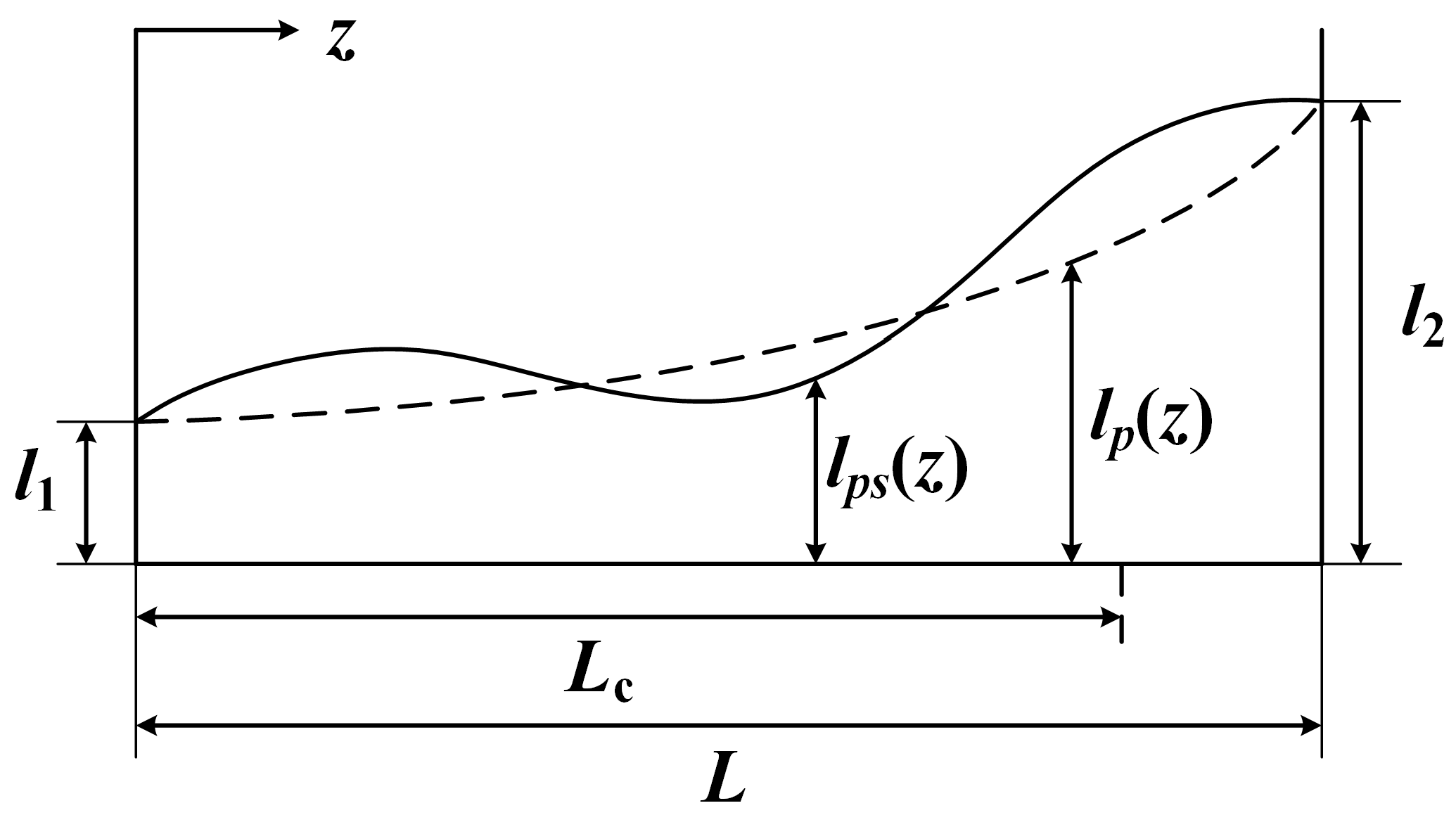
The distribution of crack height
l(
z) was also assumed to be parabolic in previous studies [
34,
36], as the dashed line shows in
Figure 11. It can be expressed as:
Considering the uncertainty of the propagation process, a sinusoidal line is added into the crack height distribution, and corresponding
l(
z) can be expressed as:
The distribution of crack angle 𝛾(
z) is assumed to be linear along the tooth width and expressed as:
Finally, for better understanding, the calculation process of a spatial cracked tooth is given in
Figure 12.
4. Results and Discussions
In this section, numerical simulations are conducted to investigate the effects of the spatial crack on the TVMS and vibration characteristics of the planetary gear system. A planetary gear set from a real application case is employed as the simulation object, which contains a sun gear (input), a fixed ring gear, a carrier (output) and four planet gears. The detailed parameters of the planetary gear set are listed in
Table 1.
Five propagation cases of the spatial crack are presented in
Figure 14. From Case 1 to Case 5, the crack propagates in the depth, length and height directions simultaneously.
Figure 14a describes the distribution of the crack depth
q(
z) along the tooth width direction, while
Figure 14b describes the distribution of the crack height
l(
z) along the tooth width direction. The distribution of the crack angle 𝛾(
z) is determined by Equation (66) with 𝛾
1 = 45° and 𝛾
2 = 90°. Detailed parameters of these propagation cases are listed in
Table 2.
4.1. Effect of the Spatial Crack Propagation on TVMS
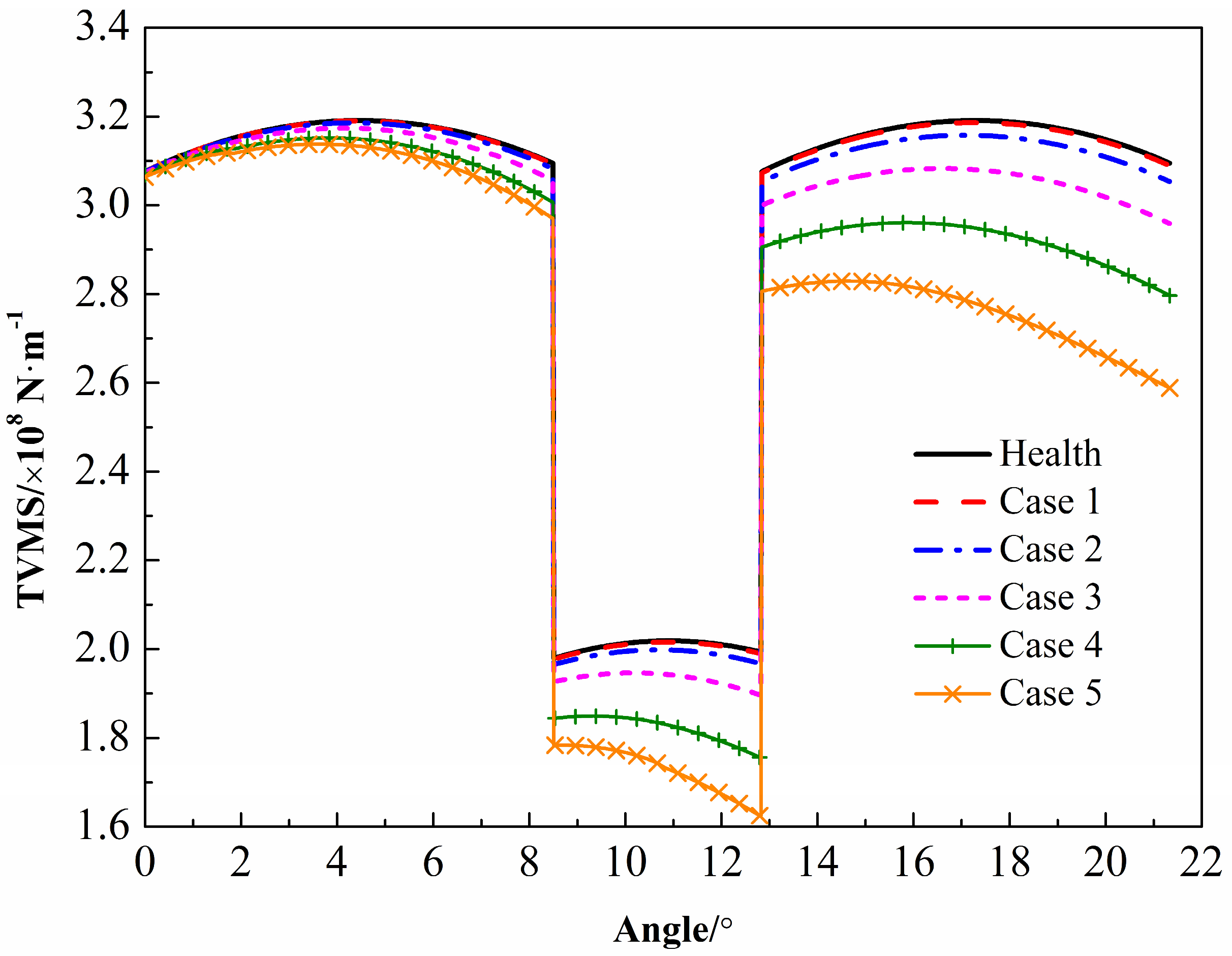
In this study, the tooth crack is estimated to occur on the sun gear.
Figure 15 presents the TVMS of the sun–planet pair in a single tooth meshing period under different crack cases. Obviously, the increase in tooth damage degree leads to the decrease in the TVMS amplitude. The horizontal axis is the rotational angle of the sun gear. With the increase in rotational angle, the meshing position moves from the tooth root to the addendum of the sun gear tooth, and the decrement amount of mesh stiffness also increases. However, it can be found that the decrement of TVMS is very limited in the early stage of tooth crack, such as in cases 1 and 2. Thus, it is hard to evaluate the damage degree by using the mesh stiffness in the early stage of tooth crack.
A planetary gear system contains
N sun–planet pairs and
N ring–planet pairs meshing simultaneously. Thus, 2
N mesh stiffness should be calculated for the following dynamic analysis.
N sun–planet pairs have same mesh stiffness, but their phases might be different. Parker and Lin [
52] investigated the mesh phase relationships of planetary gear systems and presented an efficient method to determine the phase relationships of the sun–planet pairs and ring–planet pairs. According to their method, the mesh phase of the planetary gear set in this study is listed in
Table 3. 𝛽
si (
i = 1, 2,…,
N) represents the relative phases between the
ith sun–planet pair and the first sun–planet pair, while 𝛽
ri (
i = 1, 2,…,
N) represents the relative phases between the
ith ring–planet pair and the first ring–planet pair. 𝛽
rs represents the relative phases between the
ith ring–planet pair and the
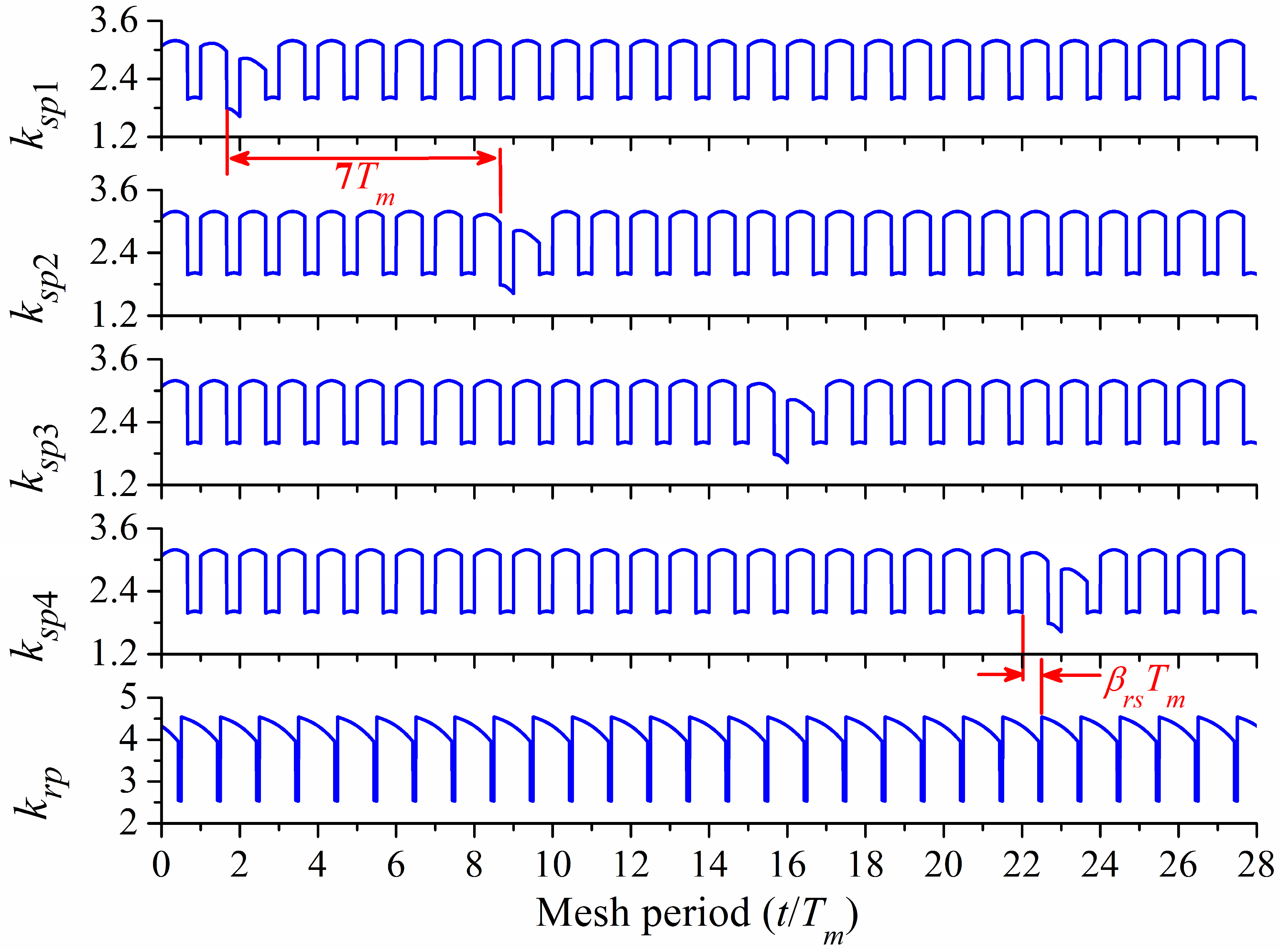
ith sun–planet pair. After obtaining these relative phases, the mesh stiffness of all sun–planet pairs and ring–planet pairs can then be obtained, and the corresponding results of case 5 are plotted in
Figure 16. As all ring–planet pairs are healthy and the relative phases 𝛽
ri are zero, the mesh stiffnesses of all ring–planet pairs are the same, represented by
krp in the fifth subgraph of
Figure 16.
Tm represents the mesh period of the planetary gear system. The horizontal axis
t/
Tm denotes the number of mesh period. As the tooth crack occurs on the sun gear, all sun–planet pairs are affected when the cracked tooth engages. The time interval between two adjacent sun–planet pair is 7
Tm, and the time interval between the sun–planet pair and the ring–planet pair is 𝛽
rsTm.
4.2. Effect of the Spatial Crack Propagation on Vibration Responses
In this section, numerical simulations are conducted to obtain the vibration responses of the planetary gear system with a spatial crack on the sun gear. The rotational speed of the sun gear is chosen as 1500 rpm, and a constant driving torque of 40 Nm is applied to the sun gear. Corresponding rotational frequencies of the sun, planet and carrier can be obtained as
fs = 25 Hz,
fp = 10.29 Hz and
fc = 5.65 Hz. The mesh frequency
fm = 541.94 Hz, and the mesh period is
Tm = 1.845 × 10
−3 s. To obtain a better understanding of the relative rotational frequency and the defect passing frequency of each component, an inverse rotation speed of carrier −
fc is applied to all components. Thus, the carrier is fixed in the equivalent motion model, and the planetary gear system can be regarded as a parallel fixed-shaft gear system. The relative rotational speeds of the sun, ring and planet gear are
fs −
fc, −
fc and
fp +
fc, respectively. As the cracked sun gear tooth contacts with each planet gear once in each revolution of the sun gear in the equivalent model, the faulty frequency of the sun gear can be obtained as:
where
frs = fs −
fc is the relative rotational frequency of the sun gear. When the rotational speed of the sun gear is 1500 rpm, the relative rotational speed of the sun gear is
frs = 19.35 Hz, and the faulty frequency is
ffs = 77.42 Hz.
As the planetary gear system contains time-varying parameters and nonlinear factors, it is hard to calculate its analytical results of vibration responses. Instead, a numerical method named Newmark-β method is employed to solve the equations of motion of the planetary gear system. The time step is assumed to be Tm/300, and the total simulation time is assumed to be 1200 Tm, so as to eliminate the transient motion.
Simulations are carried out for cases 1, 3 and 5 in
Table 2 to show the vibration responses of the slight, moderate and heavy damage degrees of the spatial crack, respectively. The torsional responses of the sun gear and the fourth planet gear are extracted to investigate the vibration features of the planetary gear system, as shown in
Figure 17 and
Figure 18, respectively. For the healthy case, the torsional motions of the sun gear and the planet gear are periodic and are mainly dominated by the excitations of the TVMS and the transmission errors. There is no impulse in the time histories of vibration signals. In case 1 (slight damage), the occurrence of the tooth crack is supposed to cause periodic impulses in the vibration signals. However, as the tooth crack of case 1 is in the initial stage, it shows very slight effects on the vibration responses so that it is hard to observe periodic impulses in the time histories. With the tooth crack propagating to case 3 (moderate damage), periodic impulses can be found, but it is still inconspicuous in the vibration signal of the sun gear, while that of the planet gear can be observed more easily. For case 5 (heavy damage), the amplitudes of the impulses increase obviously, and they are more distinct in the vibration responses of planet gear rather than the sun gear. Thus, it can be concluded that vibration signals of the planet gears are more suitable to be applied to reflect the health condition.
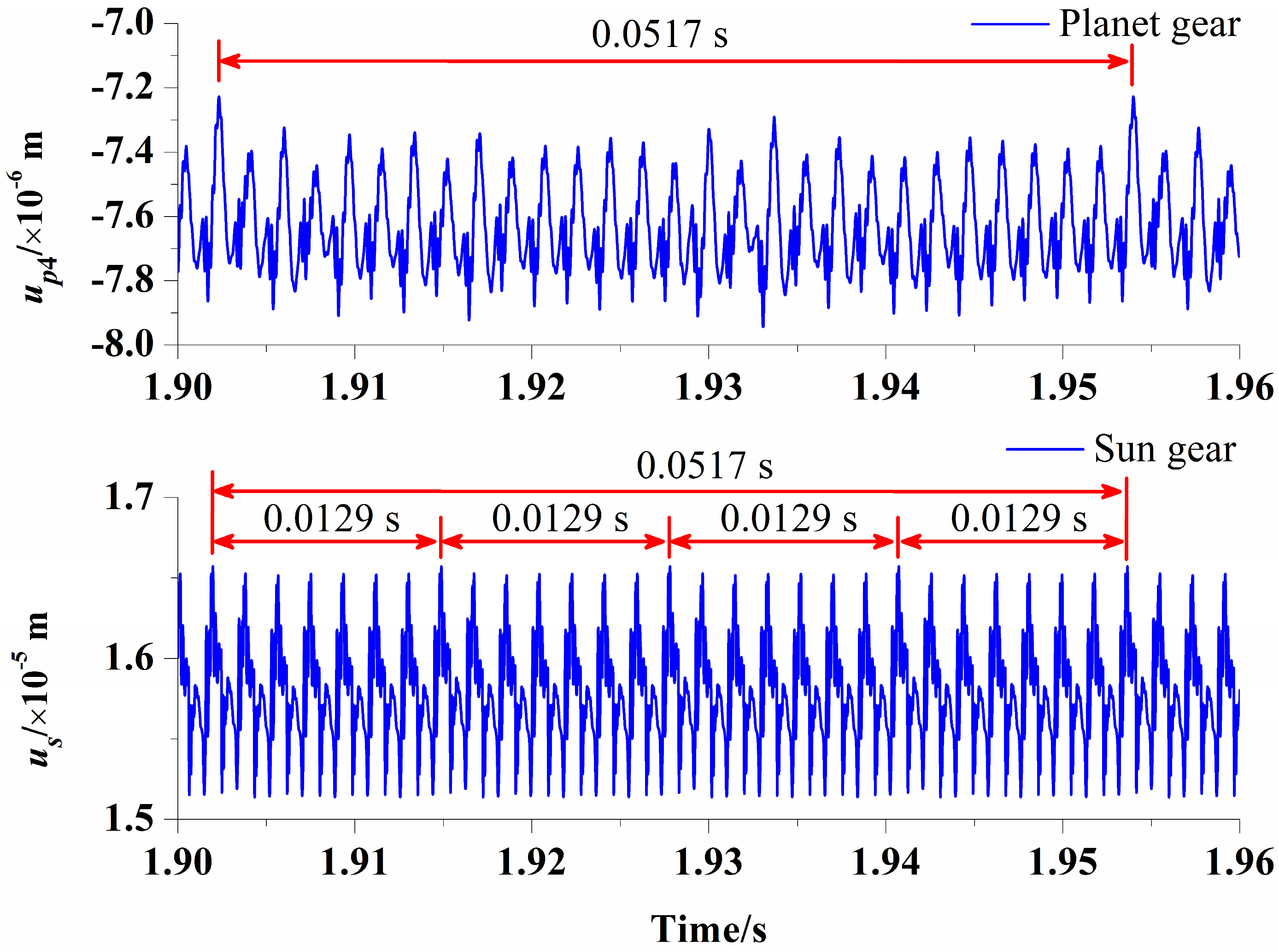
However, by comparing the time histories of the sun gear and those of the planet gear, the time intervals of two adjacent impulses are 0.0129 s for the sun gear and 0.0517 s for the planet gear, which are consistent with the faulty frequency 1/
ffs and the relative rotational frequency of the sun gear 1/
frs, respectively. The enlarged views between 1.90 and 1.96 s of case 5 for two gears are plotted in
Figure 19. In the enlarged view of vibration responses on the planet gear, 28 periodic motions can be observed between two adjacent impulses, which is exactly equal to the tooth number of sun gear
zs, as the cracked sun gear tooth meshes with the fourth planet gear once per revolution. However, as there are four planet gears, the cracked sun gear tooth meshes with each planet gear once per revolution, and four impulses can be observed in the vibration responses on the sun gear. Seven periodic motions can be observed between two adjacent impulses, as the cracked sun gear tooth meshes with a planet gear tooth once every
zs/
N mesh periods.
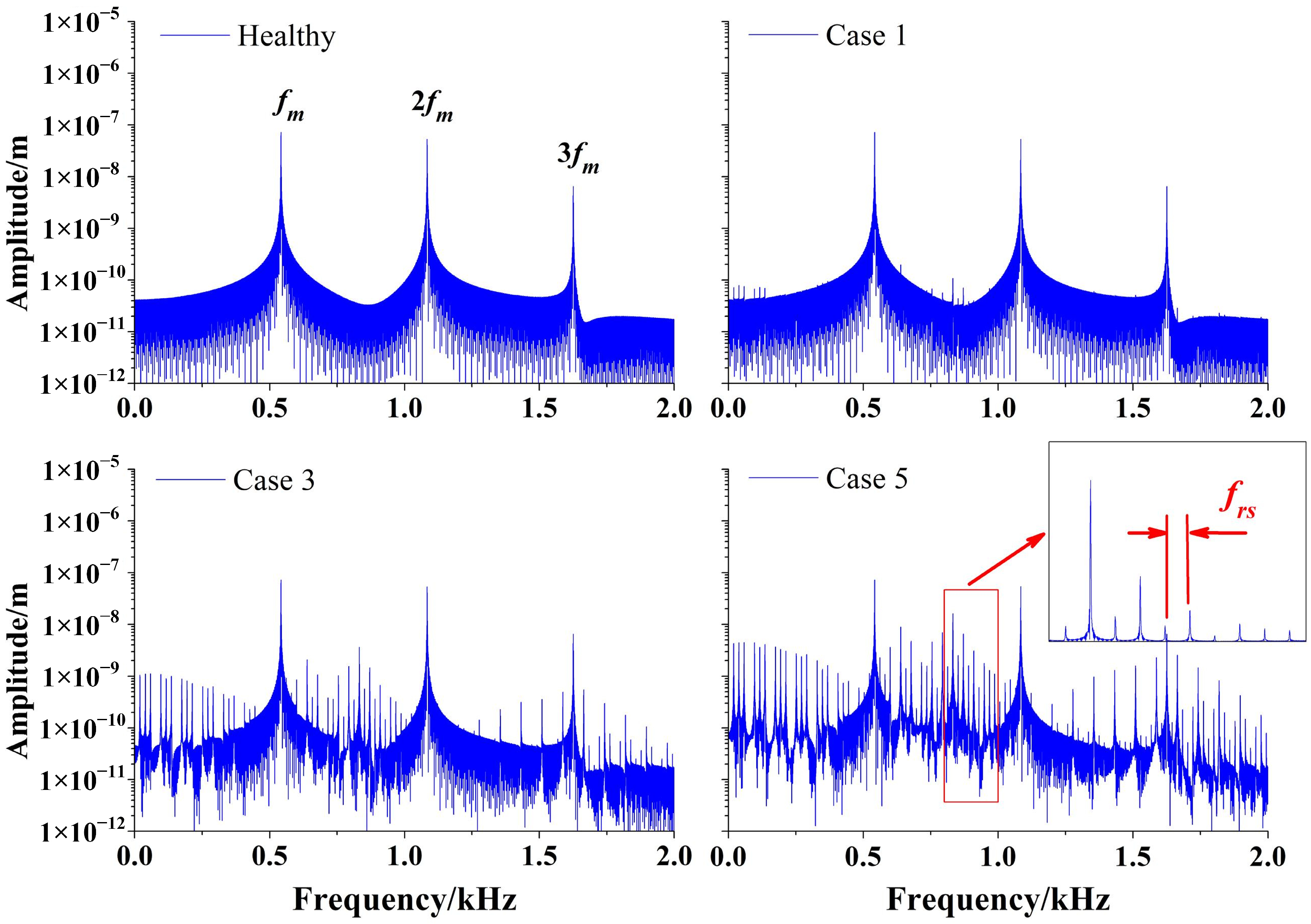
The frequency spectrums of vibration responses on the sun gear and the fourth planet gear are depicted in
Figure 20 and
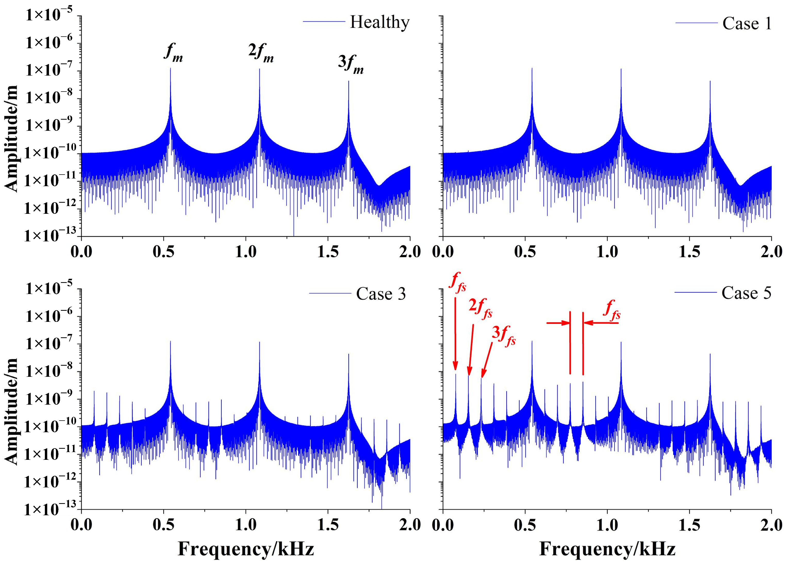
Figure 21, respectively. The spectrum of the healthy case consists of mesh frequency
fm and its harmonics. The tooth crack is supposed to induce sidebands in the frequency spectrums. However, it is hard to observe sidebands for case 1, as the tooth crack is in the early stage. When the tooth crack propagates to case 3 and case 5, the sideband becomes obvious, and its amplitude increases correspondingly. This means that the sideband of frequency spectrum could reflect the tooth crack except for in the early stage. For the frequency spectrum of the sun gear, the frequency interval of the sideband is exactly the faulty frequency
ffs, while that of the planet gear is the relative rotational frequency
frs. The reason is the same as that explained above.
4.3. Experimental Verification
In this section, the proposed model of the planetary gear system with a tooth crack defect is verified based on an experimental test rig. The experimental test rig consists of a driving motor, a spur bevel gear pair, a two-stage planetary gear set, a spur gearbox and a load motor, as shown in
Figure 22. Different types of gear faults can be seeded into any gear of the test rig to achieve the experimental study of the gear transmission system. In this study, the vibration responses and fault features of the first planetary gear set are concerned, and a tooth crack is seeded into the sun gear. The first planetary gear set contains three planet gears. The tooth numbers of the sun gear, planet gear and the ring gear are 32, 40 and 112, respectively. The tooth numbers of the driving bevel gear and the driven bevel gear are 18 and 36, respectively. In the experimental test, the driving speed of the driving motor is 1200 rpm. Thus, the rotational speed of the sun gear in the first planetary gear set is 600 rpm. The mesh frequencies of the bevel gear pair and the first planetary gear set are
fmb = 360 Hz and
fmp = 248.89 Hz, respectively. The relative rotation frequency and faulty frequency of the sun gear are
frs = 7.78 Hz and
ffs = 23.33 Hz, respectively. The rotational frequency of the carrier in the first planetary gear set is
fc = 2.22 Hz.
A small-sized tooth crack with
q = 0.2 mm is seeded in a sun gear tooth of the first planetary gear set, which can be regarded as a slight crack case.
Figure 23 shows the frequency spectrum of the experimental vibration response of the test rig. Obviously, the spectrum of the whole gear transmission system not only contains the mesh frequency of the first planetary gear set
fmp and 2
fmp, but also the mesh frequency of the bevel gear pair
fmb. Furthermore,
fmb is the dominant frequency, as the planetary gear set operates more stably with a lower vibration level than the spur bevel gear. Comparing the spectrum of the healthy case and that of the cracked case in
Figure 23a, the sideband due to the tooth crack can be hardly observed, as the crack size is small. Thus, it is hard for the spectrum sideband to reflect the early stage tooth crack, which is consistent with the simulation analysis results above.
The partial enlarged view of the spectrum around 2
fmp is presented in
Figure 23b. For the cracked case, the zoomed spectrum mainly contains the mesh frequency 2
fmp and three types of sidebands: (1) the sideband with frequencies of 2
fmp ±
kfc (
k = 1, 2,…), (2) the sideband with 2
fmp ±
kfrs (
k = 1, 2,…) and (3) the sideband with 2
fmp ±
kfrs ±
mfc (
k, m = 1, 2,…). The first sideband (2
fmp ±
kfc) is caused by the amplitude modulations of the dynamic forces of the gear meshes that rotate with the carrier, because the vibration sensor is fixed on the gear box, and the transmission path of the vibration signal to the sensor is time varying that rotates with the carrier. The second sideband is induced by the tooth crack of the sun gear. The frequency interval is
frs but not
ffs, because in an actual planetary gear set, each sun–planet gear mesh is different with others. The impulse caused by the engagement of the cracked sun gear tooth with one planet gear is different from that with other planet gears. The third sideband is the coupling of the modulations of the rotational carrier and the modulations of the tooth crack. Overall, the occurrence of a tooth crack induces sidebands around the mesh frequency, which also agrees with the simulation analysis results above.


