
Motor Bearing Damage Induced by Bearing Current: A Review
Abstract
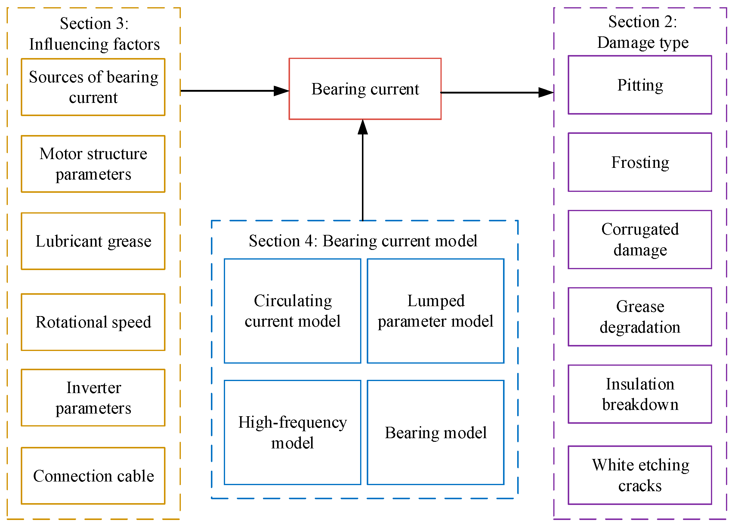
:1. Introduction
2. Damage of Bearings Caused by Bearing Currents
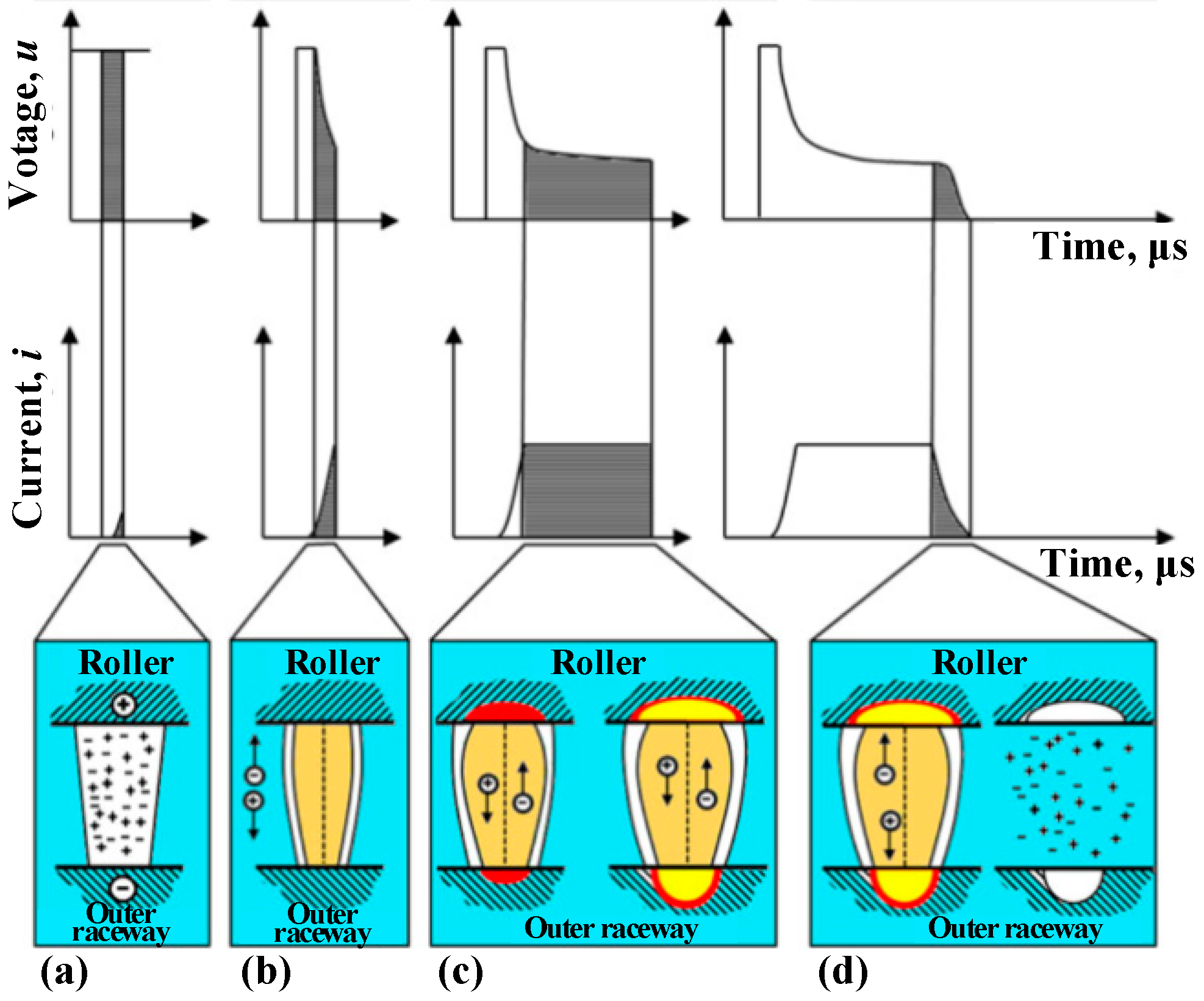
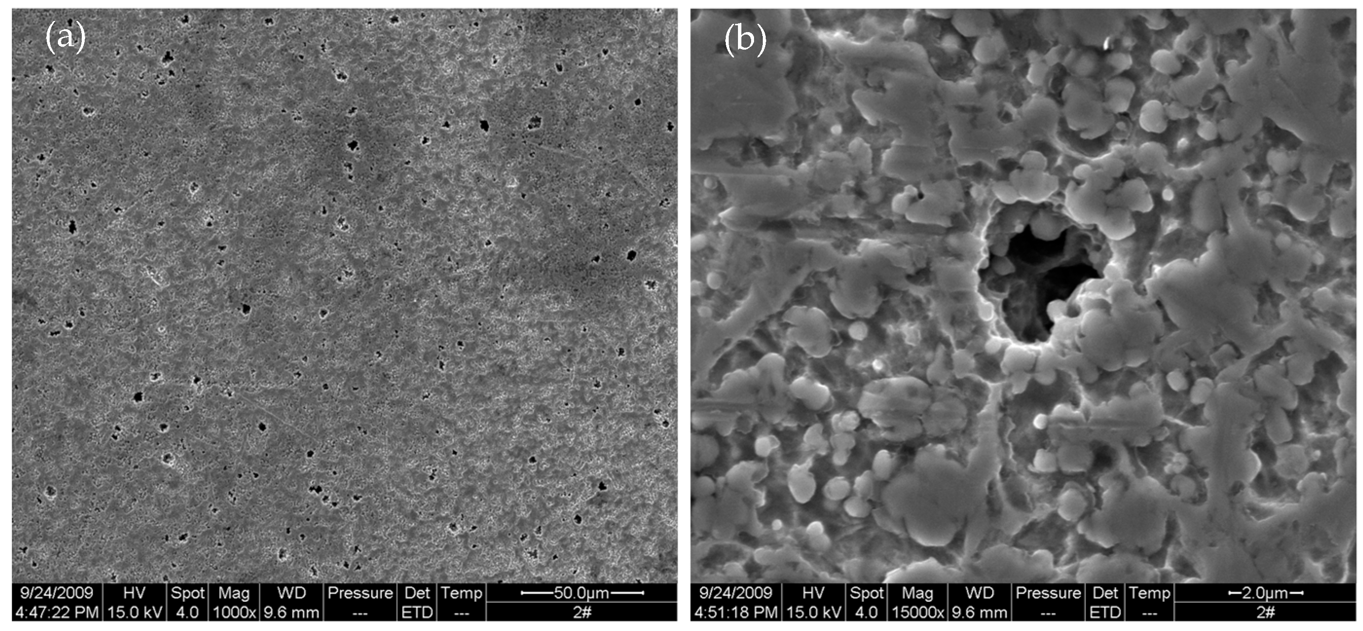
2.1. Pitting
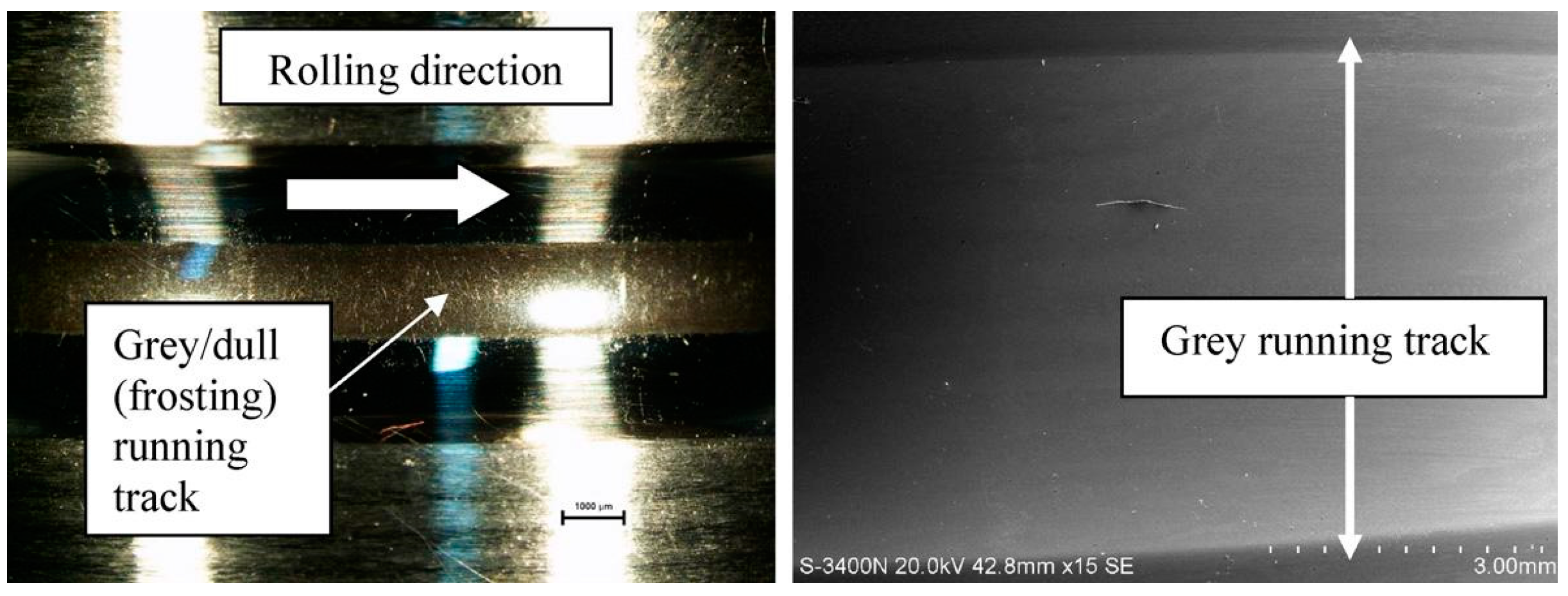
2.2. Frosting
2.3. Corrugated Damage
2.4. Grease Degradation
2.5. Insulation Breakdown
2.6. White Etching Cracks (WECs)
3. Influencing Factors of Bearing Currents
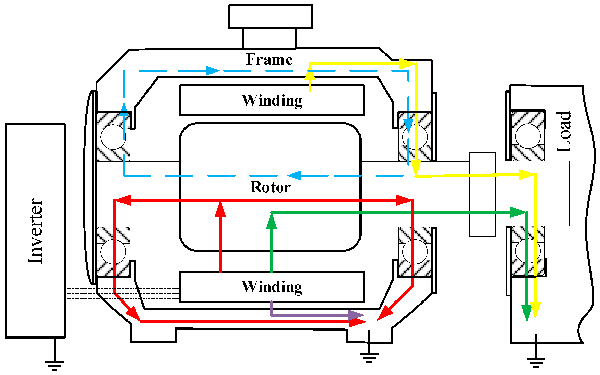
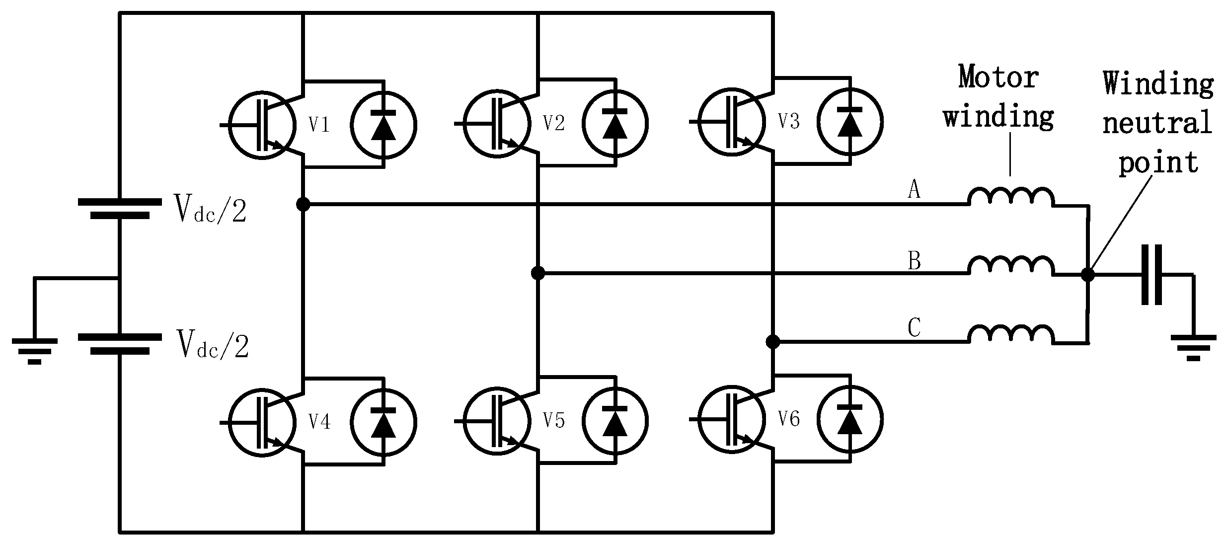
3.1. Sources of Bearing Currents
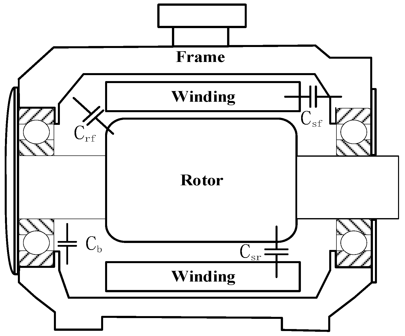
3.2. Motor Structure Parameters
3.3. Lubricant Grease
3.4. Rotational Speed
3.5. Inverter Parameters
3.6. Connection Cable
4. Modeling
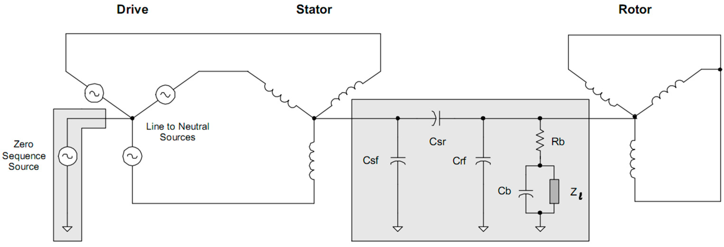
4.1. Lumped Parameter Model
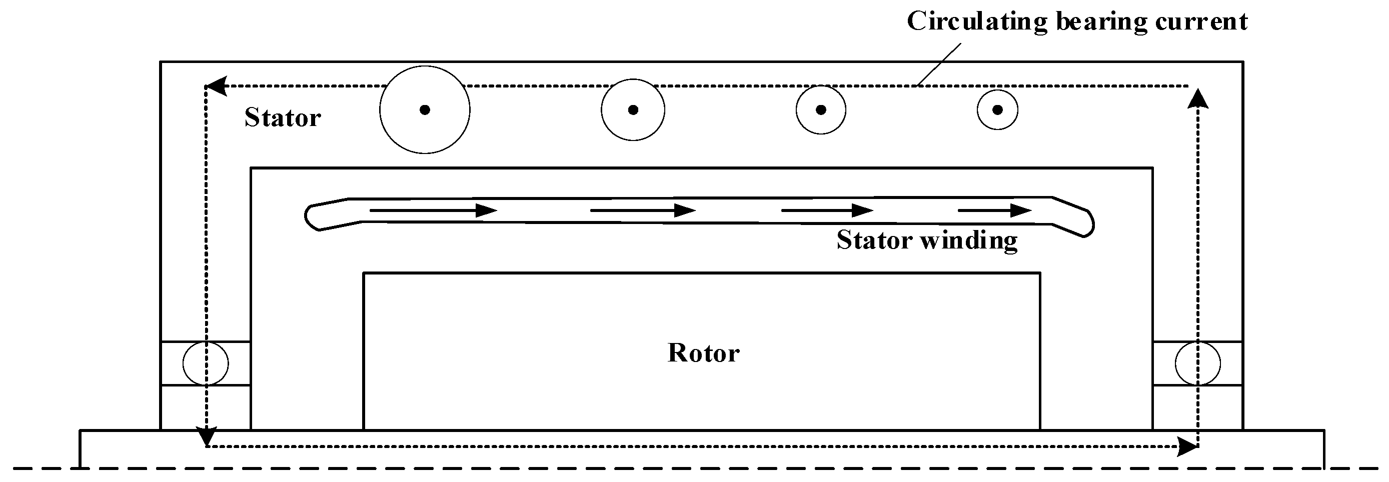
4.2. Circulating Current Model
4.3. High-Frequency Model
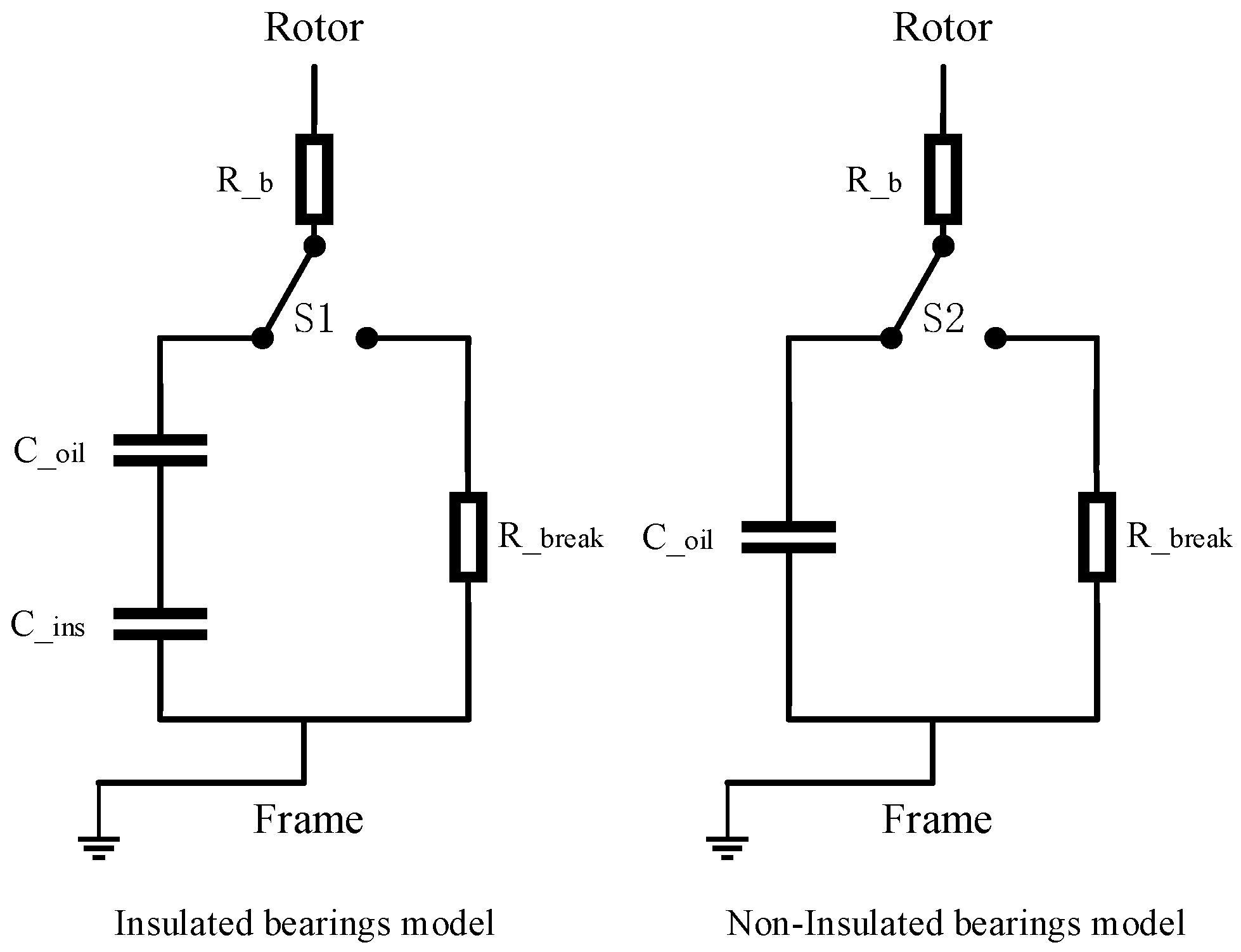
4.4. Bearing Model
5. Discussion and Outlook
- (1)
- The mechanism of bearing current generation is not clear. Many existing studies have used the bearing oil film breakdown voltage threshold proposed by Doyle et al. [90] as the condition for bearing current generation. However, insulated bearings with an insulating layer are not compatible with this method. The insulating properties of each bearing grease may vary considerably and will change as the grease deteriorates. In addition, there are factors such as load changes and grid disturbances during motor operation, and the bearing currents appear for very short periods and are more difficult to monitor. Therefore, it is very challenging to identify the conditions in which bearing currents occur.
- (2)
- The damage process of the bearing current to the bearing cannot be directly observed. The bearings are installed inside the motor and the discharge phenomenon of the bearing current occurs between the bearing rollers and the raceway, so the motor components and the roller cage of the bearings will limit visibility. In addition, the emergence of the bearing current process is very short. Thus, it is difficult to observe the damage process of bearing current on the bearing. Because of this, it is hard to determine how bearing current damage occurs.
- (3)
- The single damage area caused by the bearing current to the bearing is at the micron level and cannot be directly observed. Therefore, scanning electron microscopy is needed to observe the micro damage. Moreover, in the initial bearing current damage bearing roller and raceway surface will not be covered with bearing current damage traces, which adds difficulty to the observation of damage.
- (1)
- Consider the effect of power supply frequency on the breakdown voltage of the bearing oil film and insulation layer. The high-frequency component of the common-mode voltage and the extremely high rate of voltage change accelerate the injection of electrons into the oil film and insulation layer, increasing the density of high-energy charged particles in the oil film and insulation layer and increasing the chance of breakdown.
- (2)
- Accurate modeling of the bearing currents helps to analyze the extent of bearing current damage to the bearings. Electric vehicles have used permanent magnet synchronous motors instead of induction motors, but at high speeds, the permanent magnets in the rotor may be close to the stator winding and cut the magnetic field, thus creating the back electromagnetic fields (EMF). Inside the motor, electromagnetic interference may affect the bearing currents. Therefore, when modeling the bearing current, the electromagnetic interference between the current in the winding, and the leakage current should be considered.
- (3)
- Establish the heat source model of bearing current discharge using the heat source model of electrical discharge machining (EDM). The bearing damage caused by bearing current may be calculated by energy analysis and with the help of finite element software.
6. Concluding Remarks
Author Contributions
Funding
Data Availability Statement
Conflicts of Interest
References
- Son, D.W.; Zhang, T.; Lee, G. Study on Electrical Pitting Prevention Device of a Rotating Shaft Using Automatic Control Potential Balancing. Materials 2022, 15, 4510. [Google Scholar] [CrossRef] [PubMed]
- Schneider, V.; Behrendt, C.; Höltje, P.; Cornel, D.; Becker-Dombrowsky, F.M.; Puchtler, S.; Gutiérrez Guzmán, F.; Ponick, B.; Jacobs, G.; Kirchner, E. Electrical Bearing Damage, A Problem in the Nano- and Macro-Range. Lubricants 2022, 10, 194. [Google Scholar] [CrossRef]
- Chen, S.; Lipo, T.A.; Fitzgerald, D. Source of induction motor bearing currents caused by PWM inverters. IEEE Trans. Energy Convers. 1996, 11, 25–32. [Google Scholar] [CrossRef]
- Muetze, A. Bearing Currents in Inverter-Fed AC-Motors; Shaker-Verlag GmbH: Düren, Germany, 2004. [Google Scholar]
- Im, J.-H.; Lee, Y.-K.; Park, J.-K.; Hur, J. Shaft Voltage Reduction Method Using Carrier Wave Phase Shift in IPMSM. Energies 2021, 14, 6924. [Google Scholar] [CrossRef]
- Collin, R.; Yokochi, A.; von Jouanne, A. Novel Characterization of Si- and SiC-Based PWM Inverter Bearing Currents Using Probability Density Functions. Energies 2022, 15, 3043. [Google Scholar] [CrossRef]
- Park, J.-K.; Wellawatta, T.R.; Ullah, Z.; Hur, J. New equivalent circuit of the IPM-type BLDC motor for calculation of shaft voltage by considering electric and magnetic fields. IEEE Trans. Ind. Appl. 2016, 52, 3763–3771. [Google Scholar] [CrossRef]
- Han, P.; Heins, G.; Patterson, D.; Thiele, M.; Ionel, D.M. Modeling of Bearing Voltage in Electric Machines Based on Electromagnetic FEA and Measured Bearing Capacitance. IEEE Trans. Ind. Appl. 2021, 57, 4765–4775. [Google Scholar] [CrossRef]
- Berhausen, S.; Jarek, T. Method of Limiting Shaft Voltages in AC Electric Machines. Energies 2021, 14, 3326. [Google Scholar] [CrossRef]
- Stockbrügger, J.O.; Ponick, B. Analytical Determination of the Slot and the End-Winding Portion of the Winding-to-Rotor Capacitance for the Prediction of Shaft Voltage in Electrical Machines. Energies 2021, 14, 174. [Google Scholar] [CrossRef]
- Lin, C.-M.; Chiou, Y.-C.; Lee, R.-T. Effect of MoS2 additive on electrical pitting mechanism of lubricated surface for Babbitt alloy/bearing steel pair under ac electric field. Wear 2004, 257, 833–842. [Google Scholar] [CrossRef]
- Chiou, Y.-C.; Lee, R.-T.; Lin, S.-M. Formation mechanism of electrical damage on sliding lubricated contacts for steel pair under DC electric field. Wear 2009, 266, 110–118. [Google Scholar] [CrossRef]
- Xie, G.; Luo, J.; Guo, D.; Liu, S.; Li, G. Damages on the lubricated surfaces in bearings under the influence of weak electrical currents. Sci. China Technol. Sci. 2013, 56, 2979–2987. [Google Scholar] [CrossRef]
- von Jouanne, A.; Collin, R.; Stephens, M.; Miao, Y.; Thayil, B.; Li, C.; Agamloh, E.; Yokochi, A. Motor Bearing Current Characterization in SiC-based Variable Frequency Drive Applications. In Proceedings of the 2020 IEEE Energy Conversion Congress and Exposition (ECCE), Detroit, MI, USA, 11–15 October 2020; pp. 2718–2725. [Google Scholar]
- Ost, W.; De Baets, P. Failure analysis of the deep groove ball bearings of an electric motor. Eng. Fail. Anal. 2005, 12, 772–783. [Google Scholar] [CrossRef]
- Tischmacher, H.; Gattermann, S. Bearing currents in converter operation. In Proceedings of the XIX International Conference on Electrical Machines-ICEM 2010, Rome, Italy, 6–8 September 2010; pp. 1–8. [Google Scholar]
- Raadnui, S.; Kleesuwan, S. Electrical pitting wear debris analysis of grease-lubricated rolling element bearings. Wear 2011, 271, 1707–1718. [Google Scholar] [CrossRef]
- Prashad, H. Theoretical and experimental investigations on the pitch and width of corrugations on the surfaces of ball bearings. Wear 1991, 143, 1–14. [Google Scholar] [CrossRef]
- Prashad, H. Investigation of damaged rolling-element bearings and deterioration of lubricants under the influence of electric fields. Wear 1994, 176, 151–161. [Google Scholar] [CrossRef]
- Prashad, H. Determination of Time Span for the Appearance of Flutes on the Track Surface of Rolling-Element Bearings Under the Influence of Electric Current. Tribol. Trans. 1998, 41, 103–109. [Google Scholar] [CrossRef]
- Charoy, A.; Dunand, P. Bearing currents induced by a power drive. Automot. Power Electron. 2007, 9, 26–27. [Google Scholar]
- Didenko, T.; Pridemore, W.D. Electrical Fluting Failure of a Tri-Lobe Roller Bearing. J. Fail. Anal. Prev. 2012, 12, 575–580. [Google Scholar] [CrossRef]
- Kudelina, K.; Vaimann, T.; Rassolkin, A.; Kallaste, A.; Asad, B.; Demidova, G. Induction Motor Bearing Currents—Causes and Damages. In Proceedings of the 2021 28th International Workshop on Electric Drives: Improving Reliability of Electric Drives (IWED), Moscow, Russia, 27–29 January 2021; pp. 1–5. [Google Scholar]
- Erdman, J.M.; Kerkman, R.J.; Schlegel, D.W.; Skibinski, G.L. Effect of PWM inverters on AC motor bearing currents and shaft voltages. IEEE Trans. Ind. Appl. 1996, 32, 250–259. [Google Scholar] [CrossRef]
- Chen, S.; Lipo, T.A.; Fitzgerald, D. Modeling of motor bearing currents in PWM inverter drives. IEEE Trans. Ind. Appl. 1996, 32, 1365–1370. [Google Scholar] [CrossRef]
- Muetze, A.; Tamminen, J.; Ahola, J. Influence of Motor Operating Parameters on Discharge Bearing Current Activity. IEEE Trans. Ind. Appl. 2011, 47, 1767–1777. [Google Scholar] [CrossRef]
- Schuster, M.; Springer, J.; Binder, A. Comparison of a 1.1 kW-induction machine and a 1.5 kW-PMSM regarding common-mode bearing currents. In Proceedings of the 2018 International Symposium on Power Electronics, Electrical Drives, Automation and Motion (SPEEDAM), Amalfi, Italy, 20–22 June 2018; pp. 1–6. [Google Scholar]
- Khan, K.; Gyllensten, F. Experimental investigation of bearing currents in low voltage motors. In Proceedings of the 2018 XIII International Conference on Electrical Machines (ICEM), Alexandroupoli, Greece, 3–6 September 2018; pp. 218–224. [Google Scholar]
- Magdun, O.; Gemeinder, Y.; Binder, A. Investigation of influence of bearing load and bearing temperature on EDM bearing currents. In Proceedings of the 2010 IEEE Energy Conversion Congress and Exposition, Atlanta, GA, USA, 12–16 September 2010; pp. 2733–2738. [Google Scholar]
- Suzumura, J. Prevention of electrical pitting on rolling bearings by electrically conductive grease. Q. Rep. RTRI 2016, 57, 42–47. [Google Scholar] [CrossRef] [PubMed] [Green Version]
- Gonda, A.; Capan, R.; Bechev, D.; Sauer, B. The Influence of Lubricant Conductivity on Bearing Currents in the Case of Rolling Bearing Greases. Lubricants 2019, 7, 108. [Google Scholar] [CrossRef] [Green Version]
- Touzin, M.; Goeuriot, D.; Guerret-Piécourt, C.; Juvé, D.; Fitting, H.J. Alumina based ceramics for high-voltage insulation. J. Eur. Ceram. Soc. 2010, 30, 805–817. [Google Scholar] [CrossRef]
- Toma, F.-L.; Scheitz, S.; Berger, L.-M.; Sauchuk, V.; Kusnezoff, M.; Thiele, S. Comparative Study of the Electrical Properties and Characteristics of Thermally Sprayed Alumina and Spinel Coatings. J. Therm. Spray Technol. 2010, 20, 195–204. [Google Scholar] [CrossRef]
- Busse, D.F.; Erdman, J.M.; Kerkman, R.J.; Schlegel, D.W.; Skibinski, G.L. The effects of PWM voltage source inverters on the mechanical performance of rolling bearings. IEEE Trans. Ind. Appl. 1997, 33, 567–576. [Google Scholar] [CrossRef]
- Pietroff, H. Wälzlager im elektrischen Stromkreis (Bearings in the electrical circuit). Elektr. Bahnen 1968, 3, 54–61. [Google Scholar]
- Busse, D.; Erdman, J.; Kerkman, R.J.; Schlegel, D.; Skibinski, G. System electrical parameters and their effects on bearing currents. IEEE Trans. Ind. Appl. 1997, 33, 577–584. [Google Scholar] [CrossRef]
- Mütze, A.; Binder, A.; Vogel, H.; Hering, J. Experimental evaluation of the endangerment of ball bearings due to inverter-induced bearing currents. In Proceedings of the Conference Record of the 2004 IEEE Industry Applications Conference, 2004. 39th IAS Annual Meeting, Seattle, WA, USA, 3–7 October 2004; pp. 1989–1995. [Google Scholar]
- Loos, J.; Bergmann, I.; Goss, M. Influence of High Electrical Currents on WEC Formation in Rolling Bearings. Tribol. Trans. 2021, 64, 708–720. [Google Scholar] [CrossRef]
- Noguchi, S.; Korenaga, A.; Kanada, T. Occurrence Condition of Electric Current Density in Electrical Pitting. J. Adv. Mech. Des. Syst. Manuf. 2010, 4, 469–479. [Google Scholar] [CrossRef]
- Safdarzadeh, O.; Weicker, M.; Binder, A. Steady-state Thermal Analysis of the Contact in Bearings Exposed to Electrical Currents. In Proceedings of the IECON 2021—47th Annual Conference of the IEEE Industrial Electronics Society, Toronto, ON, Canada, 13–16 October 2021; pp. 1–6. [Google Scholar]
- Chiou, Y.-C.; Lee, R.-T.; Lin, C.-M. Formation criterion and mechanism of electrical pitting on the lubricated surface under AC electric field. Wear 1999, 236, 62–72. [Google Scholar] [CrossRef]
- Magdun, O.; Gemeinder, Y.; Binder, A.; Reis, K. Calculation of bearing and common-mode voltages for the prediction of bearing failures caused by EDM currents. In Proceedings of the 8th IEEE Symposium on Diagnostics for Electrical Machines, Power Electronics & Drives, Bologna, Italy, 6–8 September 2011; pp. 462–467. [Google Scholar]
- Lin, C.-M.; Chiou, Y.-C.; Lee, R.-T. Pitting mechanism on lubricated surface of babbitt alloy/bearing steel pair under ac electric field. Wear 2001, 249, 132–141. [Google Scholar] [CrossRef]
- Kaufman, H.N.; Boyd, J. The Conduction of Current in Bearings. ASLE Trans. 1959, 2, 67–77. [Google Scholar] [CrossRef]
- Prashad, H. Theoretical analysis of the effects of instantaneous charge leakage on roller tracks of roller bearings lubricated with high resistivity lubricants under the influence of electric current. J. Tribol. 1990, 112, 37–43. [Google Scholar] [CrossRef]
- Prashad, H. Appearance of craters on track surface of rolling element bearings by spark erosion. Tribol. Int. 2001, 34, 39–47. [Google Scholar] [CrossRef]
- Prashad, H. Theoretical analysis of capacitive effect of roller bearings on repeated starts and stops of a machine operating under the influence of shaft voltages. J. Tribol. 1992, 114, 818–822. [Google Scholar] [CrossRef]
- Tischmacher, H.; Gattermann, S.; Kriese, M.; Wittek, E. Bearing wear caused by converter-induced bearing currents. In Proceedings of the IECON 2010–36th Annual Conference on IEEE Industrial Electronics Society, Glendale, USA, 7–10 November 2010; pp. 784–791. [Google Scholar]
- Prashad, H. Analysis of the effects of an electric current on contact temperature, contact stresses and slip band initiation on the roller tracks of roller bearings. Wear 1989, 131, 1–14. [Google Scholar] [CrossRef]
- Liu, W. The prevalent motor bearing premature failures due to the high frequency electric current passage. Eng. Fail. Anal. 2014, 45, 118–127. [Google Scholar] [CrossRef]
- Romanenko, A.; Ahola, J.; Muetze, A. Influence of electric discharge activity on bearing lubricating grease degradation. In Proceedings of the 2015 IEEE Energy Conversion Congress and Exposition (ECCE), Montreal, QC, Canada, 20–24 September 2015; pp. 4851–4852. [Google Scholar]
- Muetze, A.; Binder, A.; Vogel, H.; Hering, J. What can bearings bear? IEEE Ind. Appl. Mag. 2006, 12, 57–64. [Google Scholar] [CrossRef]
- Noguchi, S.; Kakinuma, S.-n.; Kanada, T. Measurement of Direct Current Voltage Causing Electrical Pitting. J. Adv. Mech. Des. Syst. Manuf. 2010, 4, 1084–1094. [Google Scholar] [CrossRef] [Green Version]
- Romanenko, A.; Muetze, A.; Ahola, J. Effects of Electrostatic Discharges on Bearing Grease Dielectric Strength and Composition. IEEE Trans. Ind. Appl. 2016, 52, 4835–4842. [Google Scholar] [CrossRef]
- Matsumoto, K.; Sasaki, A.; Yoshida, N.; Watanabe, H. Surface Damage under Tribological Conditions Induced by Electrical Discharge. Tribol. Online 2019, 14, 214–219. [Google Scholar] [CrossRef] [Green Version]
- Komatsuzaki, S.; Uematsu, T.; Nakano, F. Bearing damage by electrical wear and its effect on deterioration of lubricating greases. Lubr. Eng. 1987, 43, 25–30. [Google Scholar]
- Malec, D.; Bley, V.; Talbi, F.; Lalam, F. Contribution to the understanding of the relationship between mechanical and dielectric strengths of Alumina. J. Eur. Ceram. Soc. 2010, 30, 3117–3123. [Google Scholar] [CrossRef]
- Zhang, T.; Du, J.; Lei, Y.; Yi, X.; Yin, J.; Yu, P. Contributing to the understanding of the dielectric breakdown channel of alumina under high voltage. Ceram. Int. 2019, 45, 16608–16611. [Google Scholar] [CrossRef]
- Neusel, C.; Jelitto, H.; Schneider, G.A. Electrical conduction mechanism in bulk ceramic insulators at high voltages until dielectric breakdown. J. Appl. Phys. 2015, 117, 154902. [Google Scholar] [CrossRef]
- Yoshimura, M.; Bowen, H. Electrical breakdown strength of alumina at high temperatures. J. Am. Ceram. Soc. 1981, 64, 404–410. [Google Scholar] [CrossRef]
- Touzin, M.; Gœuriot, D.; Fitting, H.-J.; Guerret-Piecourt, C.; Juvé, D.; Tréheux, D. Relationships between dielectric breakdown resistance and charge transport in alumina materials—Effects of the microstructure. J. Eur. Ceram. Soc. 2007, 27, 1193–1197. [Google Scholar] [CrossRef]
- Malec, D.; Bley, V.; Lebey, T. Investigations on dielectric breakdown of ceramic materials. In Proceedings of the CEIDP’05. 2005 Annual Report Conference on Electrical Insulation and Dielectric Phenomena, Nashville, TN, USA, 16–19 October 2005; pp. 63–66. [Google Scholar]
- Liebault, J.; Vallayer, J.; Goeuriot, D.; Treheux, D.; Thevenot, F. How the trapping of charges can explain the dielectric breakdown performance of alumina ceramics. J. Eur. Ceram. Soc. 2001, 21, 389–397. [Google Scholar] [CrossRef]
- Yin, Z.; Tao, S.; Zhou, X. Effect of the thickness on properties of Al2O3 coatings deposited by plasma spraying. Mater. Charact. 2011, 62, 90–93. [Google Scholar] [CrossRef]
- Neusel, C.; Jelitto, H.; Schmidt, D.; Janßen, R.; Felten, F.; Schneider, G.A. Thickness-dependence of the breakdown strength: Analysis of the dielectric and mechanical failure. J. Eur. Ceram. Soc. 2015, 35, 113–123. [Google Scholar] [CrossRef] [Green Version]
- Gould, B.; Demas, N.; Erck, R.; Lorenzo-Martin, M.C.; Ajayi, O.; Greco, A. The effect of electrical current on premature failures and microstructural degradation in bearing steel. Int. J. Fatigue 2021, 145, 106078. [Google Scholar] [CrossRef]
- Gould, B.; Greco, A.; Stadler, K.; Vegter, E.; Xiao, X. Using advanced tomography techniques to investigate the development of White Etching Cracks in a prematurely failed field bearing. Tribol. Int. 2017, 116, 362–370. [Google Scholar] [CrossRef]
- Katayama, T.; Ogitsu, T.; Kokumai, H.; Takemura, H.; Nakayama, T.; Mizoguchi, H. Study on effect of neutral voltages on shaft voltages causing bearing currents. In Proceedings of the IECON 2013-39th Annual Conference of the IEEE Industrial Electronics Society, Vienna, Austria, 10–13 November 2013; pp. 4690–4693. [Google Scholar]
- Plazenet, T.; Boileau, T.; Caironi, C.C.; Nahid-Mobarakeh, B. Influencing Parameters on Discharge Bearing Currents in Inverter-Fed Induction Motors. IEEE Trans. Energy Convers. 2021, 36, 940–949. [Google Scholar] [CrossRef]
- Zika, T.; Gebeshuber, I.C.; Buschbeck, F.; Preisinger, G.; Gröschl, M. Surface analysis on rolling bearings after exposure to defined electric stress. Proc. Inst. Mech. Eng. Part J J. Eng. Tribol. 2009, 223, 787–797. [Google Scholar] [CrossRef]
- Alger, P.; Samson, H. Shaft currents in electric machines. Trans. Am. Inst. Electr. Eng. 1924, 43, 235–245. [Google Scholar] [CrossRef]
- Pratt, J. Shaft voltages caused by alternating flux encircling the shaft. In Proceedings of the 1995 Seventh International Conference on Electrical Machines and Drives, Durham, UK, 11–13 September 1995; pp. 198–202. [Google Scholar]
- Torlay, J.-É.; Corenwinder, C.; Audoli, A.; Herigault, J.; Foggia, A. Analysis of shaft voltages in large synchronous generators. In Proceedings of the IEEE International Electric Machines and Drives Conference, Seattle, WA, USA, 9–12 May 1999; pp. 607–609. [Google Scholar]
- Chen, S.; Lipo, T.A. Circulating type motor bearing current in inverter drives. IEEE Ind. Appl. Mag. 1998, 4, 32–38. [Google Scholar] [CrossRef]
- Ong Raymond, K.J. An Investigation of Shaft Current in a Large Sleeve Bearing Induction Machine. Ph.D. Thesis, McMaster University, Hamilton, ON, Canada, 1999. [Google Scholar]
- Schiferl, R.; Melfi, M. Bearing current remediation options. IEEE Ind. Appl. Mag. 2004, 10, 40–50. [Google Scholar] [CrossRef]
- Vaimann, T.; Belahcen, A.; Kallaste, A. Changing of magnetic flux density distribution in a squirrel-cage induction motor with broken rotor bars. Elektron. Ir Elektrotechnika 2014, 20, 11–14. [Google Scholar] [CrossRef] [Green Version]
- Boyanton, H.E.; Hodges, G. Bearing fluting [motors]. IEEE Ind. Appl. Mag. 2002, 8, 53–57. [Google Scholar] [CrossRef]
- Naik, R.; Nondahl, T.A.; Melfi, M.J.; Schiferl, R.; Jian-She, W. Circuit model for shaft voltage prediction in induction motors fed by PWM-based AC drives. IEEE Trans. Ind. Appl. 2003, 39, 1294–1299. [Google Scholar] [CrossRef]
- Adabi, J.; Zare, F.; Ledwich, G.; Ghosh, A. Leakage current and common mode voltage issues in modern AC drive systems. In Proceedings of the 2007 Australasian Universities Power Engineering Conference, Perth, Australia, 9–12 December 2007; pp. 1–6. [Google Scholar]
- Ollila, J.; Hammar, T.; Iisakkala, J.; Tuusa, H. On the bearing currents in medium power variable speed AC drives. In Proceedings of the 1997 IEEE International Electric Machines and Drives Conference Record, Milwaukee, Wl, USA, 18–21 May 1997; pp. MD1/1.1–MD1/1.3. [Google Scholar]
- Muetze, A.; Binder, A. Practical Rules for Assessment of Inverter-Induced Bearing Currents in Inverter-Fed AC Motors up to 500 kW. IEEE Trans. Ind. Electron. 2007, 54, 1614–1622. [Google Scholar] [CrossRef]
- Boucenna, N.; Hlioui, S.; Revol, B.; Costa, F. A detailed analysis of the propagation paths of high-frequency common mode currents in AC motors. In Proceedings of the 2013 15th European Conference on Power Electronics and Applications (EPE), Lille, France, 2–6 September 2013; pp. 1–6. [Google Scholar]
- Schuster, M.; Masendorf, D.; Binder, A. Two PMSMs and the influence of their geometry on common-mode bearing currents. In Proceedings of the 2016 XXII International Conference on Electrical Machines (ICEM), Lausanne, Switzerland, 4–7 September 2016; pp. 2126–2132. [Google Scholar]
- Peng, B.; Wang, X.; Zhao, W.; Ren, J. Study on Shaft Voltage in Fractional Slot Permanent Magnet Machine With Different Pole and Slot Number Combinations. IEEE Trans. Magn. 2019, 55, 1–5. [Google Scholar] [CrossRef]
- Han, P.; Zhang, Y.; Kesgin, M.G.; Heins, G.; Patterson, D.; Thiele, M.; Ionel, D.M. On the Modeling of Bearing Voltage and Current in PWM Converter-fed Electric Machines Using Electromagnetic Finite Element Analysis. In Proceedings of the 2021 IEEE Energy Conversion Congress and Exposition (ECCE), Vancouver, BC, Canada, 10–14 October 2021; pp. 4606–4610. [Google Scholar]
- Muetze, A.; De Gersem, H.; Weiland, T. Influence of teeth and cooling ducts on the high-frequency common mode flux of inverter-fed ac machines. In Proceedings of the Fourtieth IAS Annual Meeting. Conference Record of the 2005 Industry Applications Conference, Hong Kong, China, 2–6 October 2005; pp. 1350–1356. [Google Scholar]
- Wang, F. Motor shaft voltages and bearing currents and their reduction in multilevel medium-voltage PWM voltage-source-inverter drive applications. IEEE Trans. Ind. Appl. 2000, 36, 1336–1341. [Google Scholar] [CrossRef]
- Fu, C.; Zhu, W.; Zheng, Z.; Sun, C.; Yang, Y.; Lu, K. Nonlinear responses of a dual-rotor system with rub-impact fault subject to interval uncertain parameters. Mech. Syst. Signal Process. 2022, 170, 108827. [Google Scholar] [CrossRef]
- Busse, D.; Erdman, J.; Kerkman, R.J.; Schlegel, D.; Skibinski, G. Bearing currents and their relationship to PWM drives. IEEE Trans. Power Electron. 1997, 12, 243–252. [Google Scholar] [CrossRef] [Green Version]
- Jagenbrein, A.; Buschbeck, F.; Gröschl, M.; Preisinger, G. Investigation of the physical mechanisms in rolling bearings during the passage of electric current. Tribotest 2005, 11, 295–306. [Google Scholar] [CrossRef]
- Sunahara, K.; Ishida, Y.; Yamashita, S.; Yamamoto, M.; Nishikawa, H.; Matsuda, K.; Kaneta, M. Preliminary Measurements of Electrical Micropitting in Grease-Lubricated Point Contacts. Tribol. Trans. 2011, 54, 730–735. [Google Scholar] [CrossRef]
- Prashad, H. The effects of current leakage on electroadhesion forces in rolling friction and magnetic flux density distribution on the surface of rolling element bearings. J. Tribol. 1988, 110, 448–455. [Google Scholar] [CrossRef]
- Hausberg, V.; Seinsch, H. Kapazitive Lagerspannungen und-ströme bei umrichtergespeisten Induktionsmaschinen. Electr. Eng. 2000, 82, 153–162. [Google Scholar] [CrossRef]
- Tischmacher, H.; Gattermann, S. Investigations on bearing currents in converter-fed electrical motors. In Proceedings of the 2012 XXth International Conference on Electrical Machines, Marseille, France, 2–5 September 2012; pp. 1764–1770. [Google Scholar]
- Zheng, J.; Xiang, D.; Li, H.; Quach, D.-C. An Investigation into the Effect of Bearing Grease Degradation on the High-frequency $ dv/dt $ Bearing Current in an Inverter-fed Motor System. In Proceedings of the 2021 6th International Conference on Power and Renewable Energy (ICPRE), Shanghai, China, 17–20 September 2021; pp. 543–547. [Google Scholar]
- Bhattacharya, S.; Resta, L.; Divan, D.M.; Novotny, D.W.; Lipo, T.A. Experimental comparison of motor bearing currents with PWM hard and soft switched voltage source inverters. In Proceedings of the PESC Record. 27th Annual IEEE Power Electronics Specialists Conference, Baveno, Italy, 23–27 June 1996; pp. 1528–1534. [Google Scholar]
- Niskanen, V.; Muetze, A.; Ahola, J. Study on Bearing Impedance Properties at Several Hundred Kilohertz for Different Electric Machine Operating Parameters. IEEE Trans. Ind. Appl. 2014, 50, 3438–3447. [Google Scholar] [CrossRef]
- Kriese, M.; Wittek, E.; Gattermann, S.; Tischmacher, H.; Poll, G.; Ponick, B. Prediction of motor bearing currents for converter operation. In Proceedings of the XIX International Conference on Electrical Machines-ICEM 2010, Rome, Italy, 6–8 September 2010; pp. 1–6. [Google Scholar]
- Noguchi, S.; Fukuda, E.; Kanada, T. Effect of Oil Film Parameter on Vibration Acceleration and Electrical Pitting of Small Ball Bearing. Tribol. Online 2012, 7, 33–40. [Google Scholar] [CrossRef]
- Smolenski, R.; Kempski, A.; Bojarski, J. Statistical approach to discharge bearing currents. COMPEL—Int. J. Comput. Math. Electr. Electron. Eng. 2010, 29, 647–666. [Google Scholar] [CrossRef]
- Xu, Y.; Liang, Y.; Yuan, X.; Wu, X.; Li, Y. Experimental Assessment of High Frequency Bearing Currents in an Induction Motor Driven by a SiC Inverter. IEEE Access 2021, 9, 40540–40549. [Google Scholar] [CrossRef]
- Reddy, S.; Basavaraja, B. Simulation and analysis of common mode voltage, bearing voltage and bearing current in two-level and three-level PWM inverter fed induction motor drive with long cable. In Proceedings of the 2015 International Conference on Power and Advanced Control Engineering (ICPACE), Bangalore, India, 12–14 August 2015; pp. 221–226. [Google Scholar]
- Chandrashekar, S.; Ramachandran, A.; Reddy, M.C. Simulation and experimental measurement of shaft voltage, bearing current in induction motor drive. In Proceedings of the 2017 IEEE International Conference on Power, Control, Signals and Instrumentation Engineering (ICPCSI), Chennai, India, 21–22 September 2017; pp. 732–737. [Google Scholar]
- Collin, R.; Yokochi, A.; Jouanne, A.V. Novel Characterization of Si- and SiC-based PWM Inverter Bearing Currents Using Probability Density Functions. In Proceedings of the 2021 IEEE Energy Conversion Congress and Exposition (ECCE), Vancouver, BC, Canada, 10–14 October 2021; pp. 5146–5153. [Google Scholar]
- Kriese, M.; Wittek, E.; Gattermann, S.; Tischmacher, H.; Poll, G.; Ponick, B. Influence of bearing currents on the bearing lifetime for converter driven machines. In Proceedings of the 2012 XXth International Conference on Electrical Machines, Marseille, France, 2–5 September 2012; pp. 1735–1739. [Google Scholar]
- Weicker, M.; Binder, A. Review on system parameters in variable speed AC-induction motor drives with parasitic electric bearing currents. In Proceedings of the 2021 23rd European Conference on Power Electronics and Applications (EPE’21 ECCE Europe), Ghent, Belgium, 6–10 September 2021; pp. 1–8. [Google Scholar]
- Mütze, A.; Binder, A. Experimental evaluation of mitigation techniques for bearing currents in inverter-supplied drive-systems-investigations on induction motors up to 500 kW. In Proceedings of the IEEE International Electric Machines and Drives Conference, IEMDC’03, Madison, WI, USA, 1–4 June 2003; pp. 1859–1865. [Google Scholar]
- Adabi, J.; Zare, F.; Ghosh, A.; Lorenz, R.D. Calculations of capacitive couplings in induction generators to analyse shaft voltage. IET Power Electron. 2010, 3, 379–390. [Google Scholar] [CrossRef] [Green Version]
- Duan, M.; Ou, Z.; Deng, C. Analysis of Shaft Voltage in Rotor Permanent Magnet Synchronous Motor System for Traction. In Proceedings of the 2020 15th IEEE Conference on Industrial Electronics and Applications (ICIEA), Kristiansand, Norway, 9–13 November 2020; pp. 1908–1911. [Google Scholar]
- Maki-Ontto, P.; Kinnunen, H.; Luomi, J. Three-phase model for the circuit simulation of common-mode phenomena and shaft voltages in ac motor drive systems. In Proceedings of the IEEE International Conference on Electric Machines and Drives, San Antonio, TX, USA, 15 May 2005; pp. 437–443. [Google Scholar]
- Mirafzal, B.; Skibinski, G.L.; Tallam, R.M.; Schlegel, D.W.; Lukaszewski, R.A. Universal Induction Motor Model With Low-to-High Frequency-Response Characteristics. IEEE Trans. Ind. Appl. 2007, 43, 1233–1246. [Google Scholar] [CrossRef]
- Tagami, K.; Ogasawara, S.; Funato, H.; Kanazawa, H.; Uesugi, M.; Moizumi, K. Analysis of shaft voltage and bearing current in an inverter-fed nongrounded motor. IEEJ Trans. Ind. Appl. 2007, 127, 286–292. [Google Scholar] [CrossRef] [Green Version]
- Wang, Y.; Bai, B.; Liu, W. Research on discharging bearing currents of PWM inverter-fed variable frequency induction motor. In Proceedings of the 2014 IEEE Conference and Expo Transportation Electrification Asia-Pacific (ITEC Asia-Pacific), Hangzhou, China, 22–25 October 2014; pp. 1–6. [Google Scholar]
- Maki-Ontto, P.; Luomi, J. Induction motor model for the analysis of capacitive and induced shaft voltages. In Proceedings of the IEEE International Conference on Electric Machines and Drives, San Antonio, TX, USA, 15 May 2005; pp. 1653–1660. [Google Scholar]
- Muetze, A.; Binder, A. Calculation of circulating bearing currents in machines of inverter-based drive systems. IEEE Trans. Ind. Electron. 2007, 54, 932–938. [Google Scholar] [CrossRef]
- Kovanen, T.; Kettunen, L.; Söderlund, L. Mechanism behind high-frequency circulating bearing currents in view of motor structures. IET Sci. Meas. Technol. 2008, 2, 233–243. [Google Scholar] [CrossRef]
- Muetze, A.; Binder, A. Calculation of influence of insulated bearings and insulated inner bearing seats on circulating bearing currents in machines of inverter-based drive systems. IEEE Trans. Ind. Appl. 2006, 42, 965–972. [Google Scholar] [CrossRef]
- Postariu, D.; Chillet, C.; Roudet, J.; Boualem, B.; Périot, R. Experimental validation of the circulating-bearing-currents mathematical theory in the 20 MHz frequency range. In Proceedings of the 2009 8th International Symposium on Advanced Electromechanical Motion Systems & Electric Drives Joint Symposium, Lillie, France, 1–3 July 2009; pp. 1–4. [Google Scholar]
- Magdun, O.; Gemeinder, Y.; Binder, A. Rotor impedance of the high frequency circulating bearing current path in inverter-fed AC machines. In Proceedings of the 2013 IEEE Energy Conversion Congress and Exposition, Denver, CO, USA, 15–19 September 2013; pp. 3512–3519. [Google Scholar]
- Jaritz, M.; Jaeger, C.; Bucher, M.; Smajic, J.; Vukovic, D.; Blume, S. An improved model for circulating bearing currents in inverter-fed AC machines. In Proceedings of the 2019 IEEE International Conference on Industrial Technology (ICIT), Melbourne, VIC, Australia, 13–15 February 2019; pp. 225–230. [Google Scholar]
- Cacciato, M.; Consoli, A.; Finocchiaro, L.; Testa, A. High frequency modeling of bearing currents and shaft voltage on electrical motors. In Proceedings of the 2005 International Conference on Electrical Machines and Systems, Nanjing, China, 27–29 September 2005; pp. 2065–2070. [Google Scholar]
- Magdun, O.; Binder, A. High-Frequency Induction Machine Modeling for Common Mode Current and Bearing Voltage Calculation. IEEE Trans. Ind. Appl. 2014, 50, 1780–1790. [Google Scholar] [CrossRef]
- Bubert, A.; Zhang, J.; De Doncker, R.W. Modeling and measurement of capacitive and inductive bearing current in electrical machines. In Proceedings of the 2017 Brazilian Power Electronics Conference (COBEP), Juiz de Fora, Brazil, 19–22 November 2017; pp. 1–6. [Google Scholar]
- Quabeck, S.; Grau, V.; De Doncker, R.W. Modeling and Mitigation of Bearing Currents in Electrical Traction Drives. In Proceedings of the 2020 23rd International Conference on Electrical Machines and Systems (ICEMS), Hamamatsu, Japan, 24–27 November 2020; pp. 1101–1106. [Google Scholar]
- De Gersem, H.; Henze, O.; Weiland, T.; Binder, A. Simulation of wave propagation effects in machine windings. COMPEL—Int. J. Comput. Math. Electr. Electron. Eng. 2010, 29, 23–38. [Google Scholar] [CrossRef]
- De Vivo, B.; Lamberti, P.; Raimo, R.; Tucci, V.; Petrarca, C. Evaluation of the bearing voltage and the overshoot phase voltage in PWM inverter-fed by means of a multiconductor transmission line model. In Proceedings of the 2014 International Symposium on Power Electronics, Electrical Drives, Automation and Motion, Ischia, Italy, 18–20 June 2014; pp. 1060–1064. [Google Scholar]
- De Gersem, H.; Muetze, A. Finite-Element Supported Transmission-Line Models for Calculating High-Frequency Effects in Machine Windings. IEEE Trans. Magn. 2012, 48, 787–790. [Google Scholar] [CrossRef]
- Moreira, A.F.; Lipo, T.A.; Venkataramanan, G.; Bernet, S. High-frequency modeling for cable and induction motor overvoltage studies in long cable drives. IEEE Trans. Ind. Appl. 2002, 38, 1297–1306. [Google Scholar] [CrossRef] [Green Version]
- Svimonishvili, T.; Fan, F.; See, K.Y.; Liu, X.; Zagrodnik, M.A.; Gupta, A.K. High-frequency model and simulation for the investigation of bearing current in inverter-driven induction machines. In Proceedings of the 2016 IEEE Region 10 Conference (TENCON), Singapore, 22–25 November 2016; pp. 55–59. [Google Scholar]
- Dahl, D.; Sosnowski, D.; Schlegel, D.; Kerkman, R.; Pennings, M. Field experience identifying electrically induced bearing failures. In Proceedings of the Conference Record of 2007 Annual Pulp and Paper Industry Technical Conference, Williamsburg, VA, USA, 24–28 June 2007; pp. 155–163. [Google Scholar]
- Magdun, O.; Binder, A.; Purcarea, C.; Rocks, A.; Funieru, B. Modeling of asymmetrical cables for an accurate calculation of common mode ground currents. In Proceedings of the 2009 IEEE Energy Conversion Congress and Exposition, San Jose, CA, USA, 20–24 September 2009; pp. 1075–1082. [Google Scholar]
- Han, P.; Heins, G.; Patterson, D.; Thiele, M.; Ionel, D.M. Combined Numerical and Experimental Determination of Ball Bearing Capacitances for Bearing Current Prediction. In Proceedings of the 2020 IEEE Energy Conversion Congress and Exposition (ECCE), Detroit, MI, USA, 11–15 October 2020; pp. 5590–5594. [Google Scholar]
- Ren, X.; Liu, R.; Yang, E. Modelling of the Bearing Breakdown Resistance in Bearing Currents Problem of AC Motors. Energies 2019, 12, 1121. [Google Scholar] [CrossRef] [Green Version]
- Wang, Y.; Liu, W.; Chen, Z.; Bai, B. Calculation of high frequency bearing currents of PWM inverter-fed VF induction motor. In Proceedings of the 2014 International Power Electronics and Application Conference and Exposition, Shanghai, China, 5–8 November 2014; pp. 1428–1433. [Google Scholar]
- Kolbe, H.; Muetze, A.; Hameyer, K. Modelling of impulse currents in mechanical rolling element bearings. COMPEL—Int. J. Comput. Math. Electr. Electron. Eng. 2012, 31, 1575–1589. [Google Scholar] [CrossRef]
- Birjukovs, M.; Jakovics, A.; Holweger, W. Modelling of thermal stresses in bearing steel structure generated by electrical current impulses. In Proceedings of the IOP Conference Series Materials Science and Engineering, Riga, Latvia, 21–22 September 2017; 355, p. 012017. [Google Scholar]
- Wang, Q.; Liu, R.; Ren, X. A Method to Determine the Critical Current Value of the Bearing Electrical Corrosion. In Proceedings of the 2019 IEEE 3rd International Electrical and Energy Conference (CIEEC), Beijing, China, 7–9 September 2019; pp. 991–995. [Google Scholar]
- Muetze, A.; Binder, A. Calculation of Motor Capacitances for Prediction of the Voltage Across the Bearings in Machines of Inverter-Based Drive Systems. IEEE Trans. Ind. Appl. 2007, 43, 665–672. [Google Scholar] [CrossRef]
- Jun, J.-h.; Lee, C.-k.; Kwon, B.-i. The analysis of bearing current using common mode equivalent circuit parameters by FEM. In Proceedings of the 2005 International Conference on Electrical Machines and Systems, Nanjing, China, 29 September 2005; pp. 49–51. [Google Scholar]
- Jaeger, C.; Grinbaum, I.; Smajic, J. Numerical simulation and measurement of common-mode and circulating bearing currents. In Proceedings of the 2016 XXII International Conference on Electrical Machines (ICEM), Lausanne, Switzerland, 4–7 September 2016; pp. 486–491. [Google Scholar]
- Magdun, O.; Binder, A.; Gemeinder, Y. Representation of iron core and dielectric losses for calculation of common mode stator ground currents in inverter-fed AC machines. In Proceedings of the 2010 12th International Conference on Optimization of Electrical and Electronic Equipment, Brasov, Romania, 20–22 May 2010; pp. 371–376. [Google Scholar]
- Magdun, O.; Binder, A. An iron core impedance model for calculating high frequency common mode currents and shaft voltages in inverter-fed AC machines. In Proceedings of the International Symposium on Power Electronics Power Electronics, Electrical Drives, Automation and Motion, Sorrento, Italy, 20–22 June 2012; pp. 135–140. [Google Scholar]
- Boucenna, N.; Hlioui, S.; Revol, B.; Costa, F. Modeling of the propagation of high-frequency currents in AC motors. In Proceedings of the International Symposium on Electromagnetic Compatibility-EMC EUROPE, Rome, Italy, 17–21 September 2012; pp. 1–6. [Google Scholar]
- Gubbala, L.; Von Jouanne, A.; Enjeti, P.; Singh, C.; Toliyat, H. Voltage Distribution in the Windings of an AC Motor Subjected to High dv/dt PWM Voltages. In Proceedings of the PESC’95-Power Electronics Specialist Conference, Atlanta, GA, USA, 18–22 June 1995; pp. 579–585. [Google Scholar]
- Oyegoke, B. Voltage distribution in the stator winding of an induction motor following a voltage surge. Electr. Eng. 2000, 82, 199–205. [Google Scholar] [CrossRef]
- Sunitha, P.; Banakara, B.; Reddy, S. Modeling, simulation and analysis of common mode voltage, bearing voltage and bearing current in PWM multilevel inverter fed induction motor with long cable. In Proceedings of the 2017 2nd IEEE International Conference on Recent Trends in Electronics, Information & Communication Technology (RTEICT), Bangalore, India, 19–20 May 2017; pp. 1161–1167. [Google Scholar]
- Hamrock, B.J.; Dowson, D. Ball bearing lubrication: The elastohydrodynamics of elliptical contacts. J. Lubr. Tech. 1982, 104, 279–281. [Google Scholar] [CrossRef] [Green Version]
- Prashad, H. Theoretical evaluation of impedance, capacitance and charge accumulation on roller bearings operated under electrical fields. Wear 1988, 125, 223–239. [Google Scholar] [CrossRef]
- Wittek, E.; Kriese, M.; Tischmacher, H.; Gattermann, S.; Ponick, B.; Poll, G. Capacitances and lubricant film thicknesses of motor bearings under different operating conditions. In Proceedings of the XIX International Conference on Electrical Machines-ICEM 2010, Rome, Italy, 6–8 September 2010; pp. 1–6. [Google Scholar]
- Gemeinder, Y.; Schuster, M.; Radnai, B.; Sauer, B.; Binder, A. Calculation and validation of a bearing impedance model for ball bearings and the influence on EDM-currents. In Proceedings of the 2014 International Conference on Electrical Machines (ICEM), Berlin, Germany, 2–5 September 2014; pp. 1804–1810. [Google Scholar]
- Safdarzadeh, O.; Weicker, M.; Binder, A. Measuring of electrical currents, voltage and resistance of an axial bearing. In Proceedings of the 2021 International Aegean Conference on Electrical Machines and Power Electronics (ACEMP) & 2021 International Conference on Optimization of Electrical and Electronic Equipment (OPTIM), Brasov, Romania, 2–3 September 2021; pp. 376–382. [Google Scholar]
- Adabi, J.; Zare, F.; Ledwich, G.; Ghosh, A.; Lorenz, R.D. Bearing damage analysis by calculation of capacitive coupling between inner and outer races of a ball bearing. In Proceedings of the 2008 13th International Power Electronics and Motion Control Conference, Poznan, Poland, 1–3 September 2008; pp. 903–907. [Google Scholar]
- Wittek, E.; Kriese, M.; Tischmacher, H.; Gattermann, S.; Ponick, B.; Poll, G. Capacitance of bearings for electric motors at variable mechanical loads. In Proceedings of the 2012 XXth International Conference on Electrical Machines, Marseille, France, 2–5 September 2012; pp. 1602–1607. [Google Scholar]
- Liu, J.Y.; Tallian, T.E.; McCool, J.I. Dependence of Bearing Fatigue Life on Film Thickness to Surface Roughness Ratio. A S L E Trans. 1975, 18, 144–152. [Google Scholar] [CrossRef]
- Magdun, O.; Binder, A. Calculation of roller and ball bearing capacitances and prediction of EDM currents. In Proceedings of the 2009 35th Annual Conference of IEEE Industrial Electronics, Porto, Portugal, 3–5 November 2009; pp. 1051–1056. [Google Scholar]


| Type | Modeling Methods | Bearing Type | Parameter Acquisition | References | |
|---|---|---|---|---|---|
| Motor model | Lumped parameter model | RLC circuit | Non-insulated bearings | Analytical calculation | [24,109] |
| Finite element method, simulation, analytical calculation | [110] | ||||
| Three-Phase Model | RLC circuit | Non-insulated bearings | Analytical calculation | [7,111,112,113] | |
| insulated bearings | Analytical calculation | [114] | |||
| Distributional parameter model | RLC circuit | Non-insulated bearings | Measurement | [25] | |
| Circulating current model | Mathematical model | Analytical calculation | [115,116,117] | ||
| RLC circuit | insulated bearings | Analytical calculation | [118,119,120] | ||
| RLC circuit | Non-insulated bearings | Finite element method | [121] | ||
| High-frequency model | High-frequency model for winding | RLC circuit | Non-insulated bearings | Measurement | [79,122,123,124] |
| RLC circuit | insulated bearings | Measurement, finite element method | [125] | ||
| Transmission-line models | Finite element method | [126,127,128] | |||
| Models with power cables | RLC circuit | Analytical calculation, measurement | [111,129,130] | ||
| Analytical calculation, measurements, finite element methods | [131,132] | ||||
| Bearing model | Non-insulated bearings | RLC circuit | Analytical calculation | [24,25,133] | |
| Nonlinear resistance model at the breakdown | RLC circuit | Analytical calculation | [24,124,134] | ||
| Insulated bearings | RLC circuit | Analytical calculation | [125,135] | ||
| Discharge model | Finite element method | [136,137,138] | |||
Publisher’s Note: MDPI stays neutral with regard to jurisdictional claims in published maps and institutional affiliations. |
© 2022 by the authors. Licensee MDPI, Basel, Switzerland. This article is an open access article distributed under the terms and conditions of the Creative Commons Attribution (CC BY) license (https://creativecommons.org/licenses/by/4.0/).
Share and Cite
Ma, J.; Xue, Y.; Han, Q.; Li, X.; Yu, C. Motor Bearing Damage Induced by Bearing Current: A Review. Machines 2022, 10, 1167. https://doi.org/10.3390/machines10121167
Ma J, Xue Y, Han Q, Li X, Yu C. Motor Bearing Damage Induced by Bearing Current: A Review. Machines. 2022; 10(12):1167. https://doi.org/10.3390/machines10121167
Chicago/Turabian StyleMa, Jiaojiao, Yujian Xue, Qingkai Han, Xuejun Li, and Changxin Yu. 2022. "Motor Bearing Damage Induced by Bearing Current: A Review" Machines 10, no. 12: 1167. https://doi.org/10.3390/machines10121167