Article

Type Synthesis of 4-DOF Non-Overconstrained Parallel Mechanisms with Symmetrical Structures

1
The State Key Laboratory of Mechanical Transmissions, Chongqing University, Chongqing 400044, China
2
National and Local Joint Engineering Research Center of Reliability Analysis and Testing for Mechanical and Electrical Products, Zhejiang Sci-Tech University, Hangzhou 310018, China
3
School of Mechanical Engineering, Zhejiang Sci-Tech University, Hangzhou 310018, China
*
Author to whom correspondence should be addressed.
Machines 2022, 10(12), 1123; https://doi.org/10.3390/machines10121123
Submission received: 30 October 2022 / Revised: 23 November 2022 / Accepted: 25 November 2022 / Published: 27 November 2022
(This article belongs to the Special Issue Development and Applications of Parallel Robots)

Abstract

:
This paper presents the type synthesis of 4-DOF non-overconstrained parallel mechanisms (PMs) with symmetrical structures. A special topological structure that includes two intermediate platforms and one moving platform is employed. Constraint conditions for 3R1T, 2R2T, and 1R3T (R: rotation; T: translation) symmetrical PMs are analyzed. Several classes of hybrid limbs that exert a constraint force or a constraint couple are synthesized using screw theory. These limbs are then used to construct 4-DOF PMs, resulting in many novel non-overconstrained 3R1T, 2R2T, and 1R3T PMs with symmetrical structures. The non-overconstrained feature is verified based on the Grübler/Kutzbach criterion.

1. Introduction

The main feature of a parallel mechanism (PM) is that its moving platform is connected to a fixed base through at least two kinematic limbs. The closed-loop structure of a PM facilitates high stiffness and high load capacity, which are very welcome in industrial applications. Therefore, PMs have become a research hotspot in the field of mechanisms and robotics. The most famous PM may be the Gough-Stewart platform with 6 degrees of freedom (6-DOF). Compared to 6-DOF PMs, PMs with fewer than 6 DOFs, called low-DOF PMs, have the advantages of a simpler mechanical design, lower manufacturing cost, larger workspace, and simpler controller. On the other hand, they do not offer full DOFs in three-dimensional space and thus can be applied only to specific applications. Many low-DOF PMs, such as the 3-DOF Delta robot [1,2], 3-DOF Z3 head [3,4], and 4-DOF H4 robot [5,6], have been invented.
The number of kinematic limbs in a PM usually equals its number of DOFs, which makes it possible to have one actuator in each limb and keep all the actuators close to the fixed base. Additionally, it is a good practice to construct symmetrical PMs using identical kinematic limbs since a PM with asymmetrical limb structures usually suffers from an unsymmetrical workspace and performance, which may complicate task planning [7]. Moreover, this kind of PM incurs a higher manufacturing cost, as the number of mechanical parts is increased compared to that of a symmetrical PM. The 6-DOF Gough-Stewart platform, 3-DOF Delta robot, and 3-DOF Z3 head all have the above two characteristics.
There was once a view that a general 4-DOF or 5-DOF PM could not be constructed with identical kinematic limbs [3,8]. After screw theory was successfully introduced into the type synthesis of PMs [9,10], many 4-DOF and 5-DOF PMs with identical kinematic limbs were presented [7,11,12,13]. Other methods [14], such as the graphical type synthesis method and the method based on Lie group theory, have also resulted in some interesting 4-DOF [15,16] and 5-DOF [17] PMs. However, almost all of those PMs, such as the 3-RRC PM [18], 4-RRCR PM [19], 4-RUU PM [20], 5-RPUR PM [21,22], and 5RRRRR PM [23], are overconstrained mechanisms [24], which have full cycle mobility but do not satisfy the Grübler/Kutzbach criterion [25]. In addition to the aforementioned PMs with fixed DOFs, some PMs that have bifurcated motion or have multiple operation modes are also overconstrained, such as the 3-PUP PM [26,27], 1-RPU-2-UPU PM [28], and 3-4R PM [29]. Although overconstrained PMs have good stiffness, it is necessary to have high manufacturing accuracy and strict assembly conditions. Furthermore, inevitable internal loads may accelerate the failure of the mechanical parts. To solve these problems, researchers have focused their attention on non-overconstrained PMs. Pierrot et al. [5,30] presented the H4 robot and I4 robot, which are non-overconstrained 4-DOF PMs. Guo et al. [31] presented a systematic approach for the type synthesis of non-overconstrained 3T1R (R: rotation; T: translation) PMs. Sun et al. [32] proposed a topology synthesis of 3T1R PMs that are non-overconstrained. Although some 4-DOF non-overconstrained PMs with symmetrical structures have been reported, they belong to the 1R3 T-type PMs. The existing 2R2T PMs and 3R1T PMs with symmetrical structures [17,33] are all overconstrained mechanisms. Although some 2R2T and 3R1T PMs [34,35] are non-overconstrained, they do not have identical kinematic limbs. No non-overconstrained 2R2T and 3R1T PMs with symmetrical structures can be found in the literature.
To fill this gap, this paper presents the type synthesis of 4-DOF non-overconstrained PMs with symmetrical structures. A special topology structure is used to construct the desired PMs. Three classes of hybrid limbs that exert either a forced constraint or a coupled constraint are proposed based on screw theory. The hybrid limbs are subsequently used to synthesize non-overconstrained 4-DOF PMs, including 3R1T PMs, 2R2T PMs, and 1R3T PMs, which are presented for the first time to our knowledge.
The remainder of the paper is arranged as follows: Section 2 introduces a special topological structure that can be used to construct 4-DOF non-overconstrained PMs. Several classes of novel hybrid limbs that generate a constraint force or a constraint couple are synthesized in Section 3. Section 4 presents 4-DOF non-overconstrained PMs with symmetrical structures, and Section 5 concludes the work.

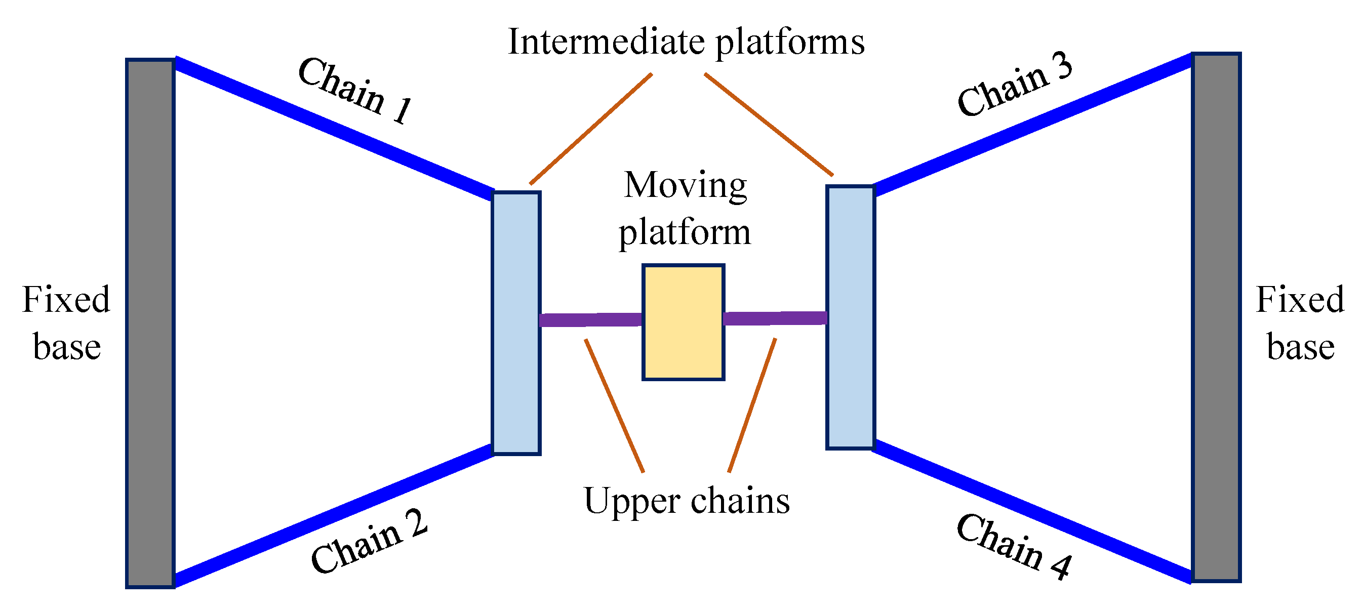
2. Topological Structure of 4-DOF PMs

In a PM, the number of kinematic limbs usually equals its DOFs. As a result, one can arrange one actuator in each limb to fully control the motion of the PM and keep all the actuators close to the fixed base to reduce the moving inertia. Since the focus of this paper is on 4-DOF PMs, the number of kinematic limbs should be four, and the number of independent constraints exerted on the moving platform should be two. Considering that the 4-DOF PMs have symmetrical structures, the constraint characteristic of all the limbs should be the same. However, this raises a problem: if all the limbs provide no constraint to the moving platform, the PM has six DOFs; alternatively, if each limb provides one constraint to the moving platform, only two of the four constraints are independent, which conflicts with the design objective of “non-overconstrained PMs.”
To solve this problem, a special PM topological structure proposed by Guo et al. [31] is applied. As shown in Figure 1, there are two intermediate platforms in the PM. The moving platform of the PM is connected to each of the two intermediate platforms by one kinematic chain, and each intermediate platform is connected to the fixed base through two kinematic chains. Chain 1, chain 2, chain 3, and chain 4 can be regarded as subchains, and each subchain can contain one actuator. In the end, such a PM has two hybrid kinematic limbs, where each hybrid limb is composed of two subchains, an intermediate platform, and an upper chain. Such a hybrid limb should provide one independent constraint. Therefore, only two independent constraints are applied to the moving platform.
Next, the structure of the hybrid limb is analyzed. There are two cases of constraint arrangements that satisfy the requirement of “non-overconstrained.” In the first case, each subchain provides one constraint, which means that the intermediate platform has four DOFs, and the upper chain has one DOF. Therefore, the hybrid limb has five DOFs and provides one constraint. In the second case, each subchain provides two constraints, which means there are four constraints in total, and the intermediate platform has two DOFs. In this case, the upper chain should have three DOFs. Considering just the mechanical structure, hybrid limbs in the first case would be more compact and have better stiffness compared to that in the second case because of the difference in the joint number of the upper chains. Therefore, the focus of this paper is on the first case, whose structure is shown in Figure 2. Each red circle in Figure 2 denotes a 1-DOF joint. The two subchains have five DOFs, and the intermediate platform has four DOFs. Combined with a 1-DOF joint in the upper chain, the hybrid limb has five DOFs.
4-DOF PMs usually output three kinds of motion, i.e., 3R1T motion, 2R2T motion, and 1R3T motion. All three kinds of motion are considered here. Since each PM is composed of two identical hybrid limbs, the constraint generated by the hybrid limbs can be obtained as follows: (a) for a PM with 3R1T motion, each hybrid limb has one constraint force, and the two constraint forces intersect at a common point, which restricts two translational DOFs of the moving platform; (b) for a PM with 2R2T motion, each hybrid limb has one constraint force, and the two forces are parallel with each other, which restricts a rotational DOF and a translational DOF; (c) for a PM with 1R3T motion, each hybrid limb generates one constraint couple, and the two constraint couples restrict the two rotational DOFs of the moving platform.
From the above analysis, we can conclude that 4-DOF PMs can be constructed using hybrid limbs that generate a constraint force or a constraint couple. These two kinds of limbs, denoted as the F-hybrid limb and the C-hybrid limb, respectively, will be synthesized in the following section.

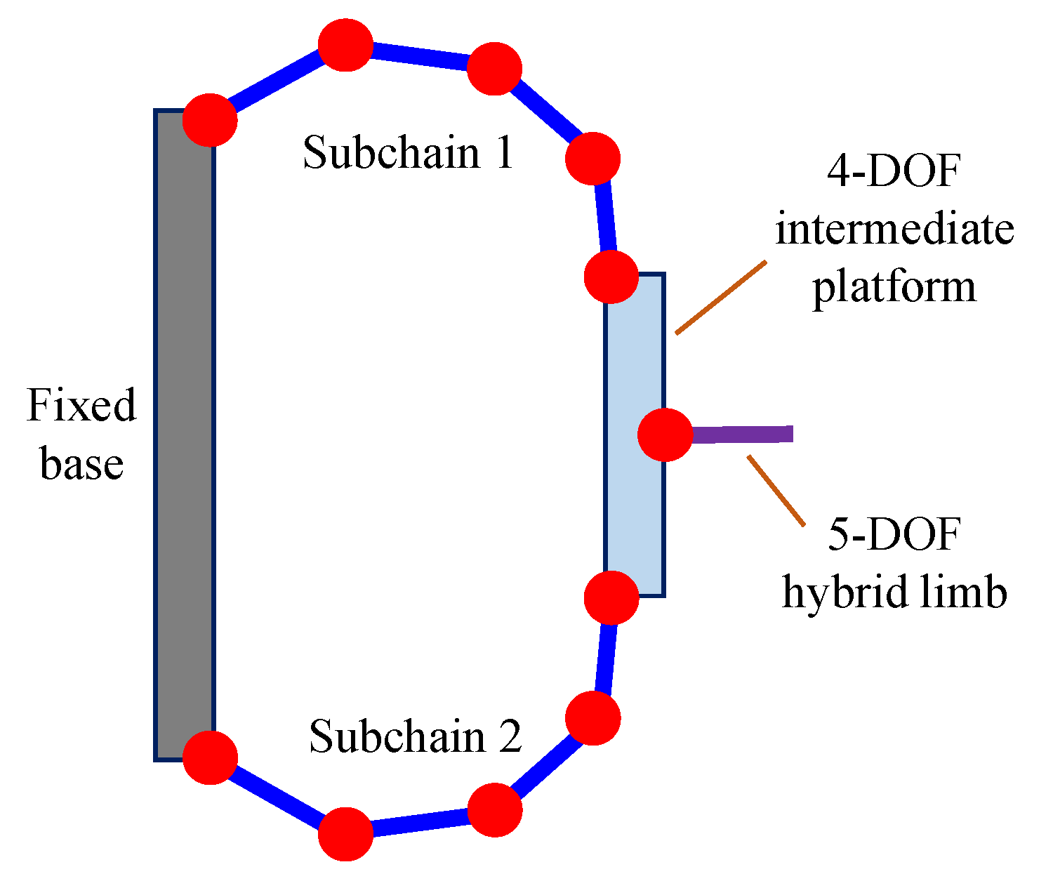
3. Construction of Hybrid Limbs

Some special geometrical conditions for kinematic limbs derived in Ref. [7] provide guidance for this paper. They are:
Condition 1: For a kinematic limb that generates a constraint force, axes of revolute joints in this limb should be parallel to or intersect with the force, and prismatic joints should have axes perpendicular to the force.
Condition 2: For a kinematic limb that generates a constraint couple, the axes of revolute joints in this limb should be perpendicular to the couple, and there are no special conditions for prismatic joints.

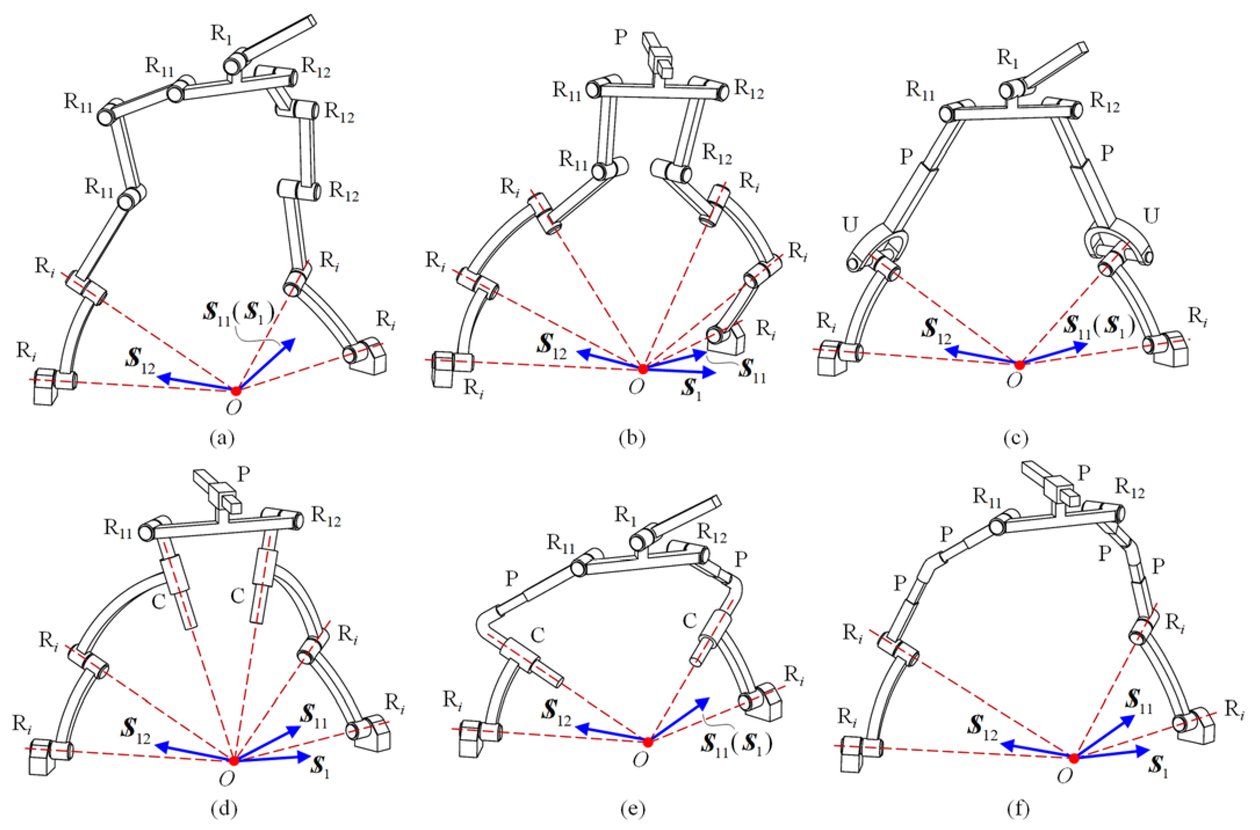
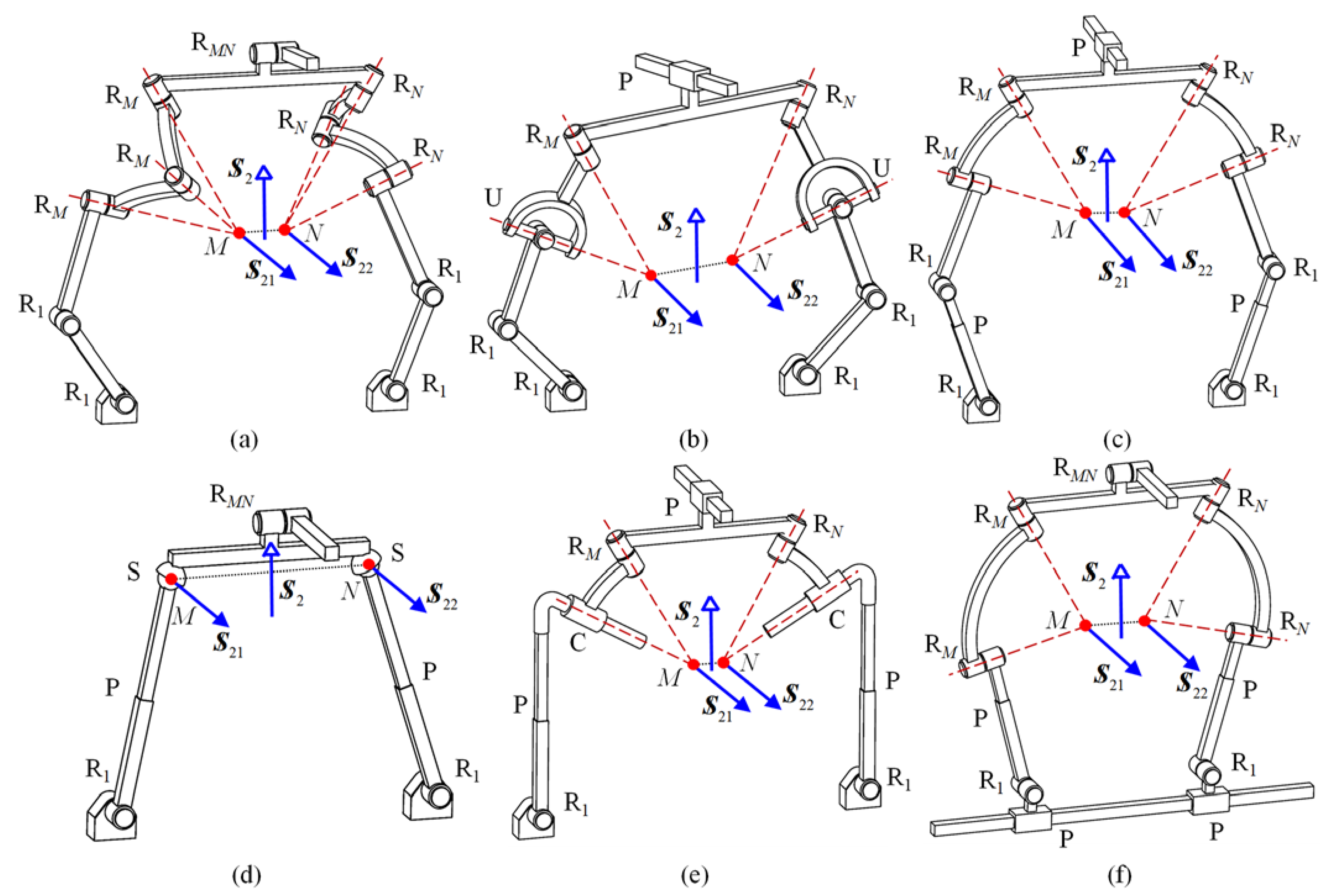
3.1. Synthesis of F-Hybrid Limbs

The constraint provided by F-hybrid limbs is a constraint force, which is represented by
S 1 = [ s 1 r O × s 1 ]
where the unit vector s1 represents the direction of the force, and rO is the position vector of the acting point of the force.
Since the two subchains have identical structures, their constraint characteristics are the same. If each subchain exerts one constraint couple, the intermediate platform will have a constraint system consisting of two constraint couples. By adding a 1-DOF upper chain, this constraint system cannot be reduced to a constraint force, which is the desired constraint of the F-hybrid limbs. Therefore, to construct F-hybrid limbs, the subchains should provide a constraint force, resulting in two constraint forces being exerted on the intermediate platform. There are two special cases of interest:
Case 1: the two forces intersect at a common point. The constraint system of the intermediate platform consists of two constraint forces that should be reduced to one constraint force by adding a 1-DOF joint, which can be a revolute joint or a prismatic joint. For simplicity, we assume that the two forces intersect at the acting point of S 1 ; thus, the constraint system S I P 1 can be represented by
S I P 1 = { S 11 = [ s 11 r O × s 11 ] S 12 = [ s 12 r O × s 12 ]
where S 11 and S 12 are two constraint forces, and unit vectors s11 and s12 denote their directions.
It is apparent that S 1 should belong to the constraint system S I P 1 , which is a constraint system consisting of two forces that intersect at a common point, with force directions s11 and s12. Therefore, a special condition should be satisfied, i.e., vector s1 should be parallel to the plane defined by vectors s11 and s12.
After adding a 1-DOF joint to the intermediate platform, the constraint of the limb will be reduced from S I P 1 to S 1 . If the added joint is a revolute joint, its axis should be parallel to S 1 ; if a prismatic joint is added, its axis should be perpendicular to S 1 . Based on kinematic chains that generate a constraint force [7], a class of F-hybrid limbs can be constructed as in Table 1.
In Table 1, Ri represents revolute joints that intersect at a common point, and R11 and R12 denote revolute joints whose axes are parallel to S 11 and S 12 , respectively. By combining multiple single-DOF joints, we can obtain a variety of composite joints such as the universal joint, cylindrical joint, and spherical joint. U denotes a universal joint that can be regarded as the combination of two revolute joints whose axes are perpendicular and intersecting. C denotes a cylindrical joint that can be regarded as the combination of a revolute joint and a prismatic joint with parallel axes. Some typical F-hybrid limbs of this class are illustrated in Figure 3.
In Figure 3, S 1 denotes the constraint of the F-hybrid limbs and S 11 and S 12 denote the constraints of the two subchains. In Figure 3a,c,e, the added revolute joint axis is parallel to the axis of R11. Therefore, S 1 is coincident with S 11 . In Figure 3b,d,f, S 1 lies on the plane formed by S 11 and S 12 and is perpendicular to the added prismatic joint.
Case 2: the two forces are parallel to each other. To obtain the hybrid limb’s constraint in Equation (1), the two forces should be parallel to S 1 ; thus, the constraint system S I P 2 can be represented by
S I P 2 = { S 21 = [ s 1 r M × s 1 ] S 22 = [ s 1 r N × s 1 ]
where rM and rN are position vectors of constraint forces S 21 and S 22 .
Subtracting S 21 from S 22 , a new constraint screw can be obtained as
S 23 = [ 0 M N × s 1 ]
where MN is a vector from point M to point N.
Similarly, considering that S 1 should also be included in the constraint system S I P 2 , two other screws can be obtained as
S 24 = [ 0 M O × s 1 ]
S 25 = [ 0 O N × s 1 ]
where MO is a vector from point M to point O, and ON is a vector from point O to point N.
To ensure that S I P 2 has only two independent screws, the three constraint couples in Equations (4)–(6) should be the same, which means points O, M, and N should be located along the same line.
The constraint screw in Equation (4) indicates that S I P 2 inherently includes a constraint couple, which should be eliminated through the additional upper chain. Therefore, the upper chain should contain a revolute joint, and the axis of this joint should pass through point O to determine the location of the constraint force in Equation (1). A class of F-hybrid limbs can be constructed, as shown in Table 2.
In Table 2, R1 represents a revolute joint whose axis is parallel to S 1 . RM, RN, and RO denote revolute joints whose axes intersect at points M, N, and O, respectively. S denotes a spherical joint that is the combination of three revolute joints whose axes intersect at a common point. Figure 4 shows some typical F-hybrid limbs belonging to the second class.

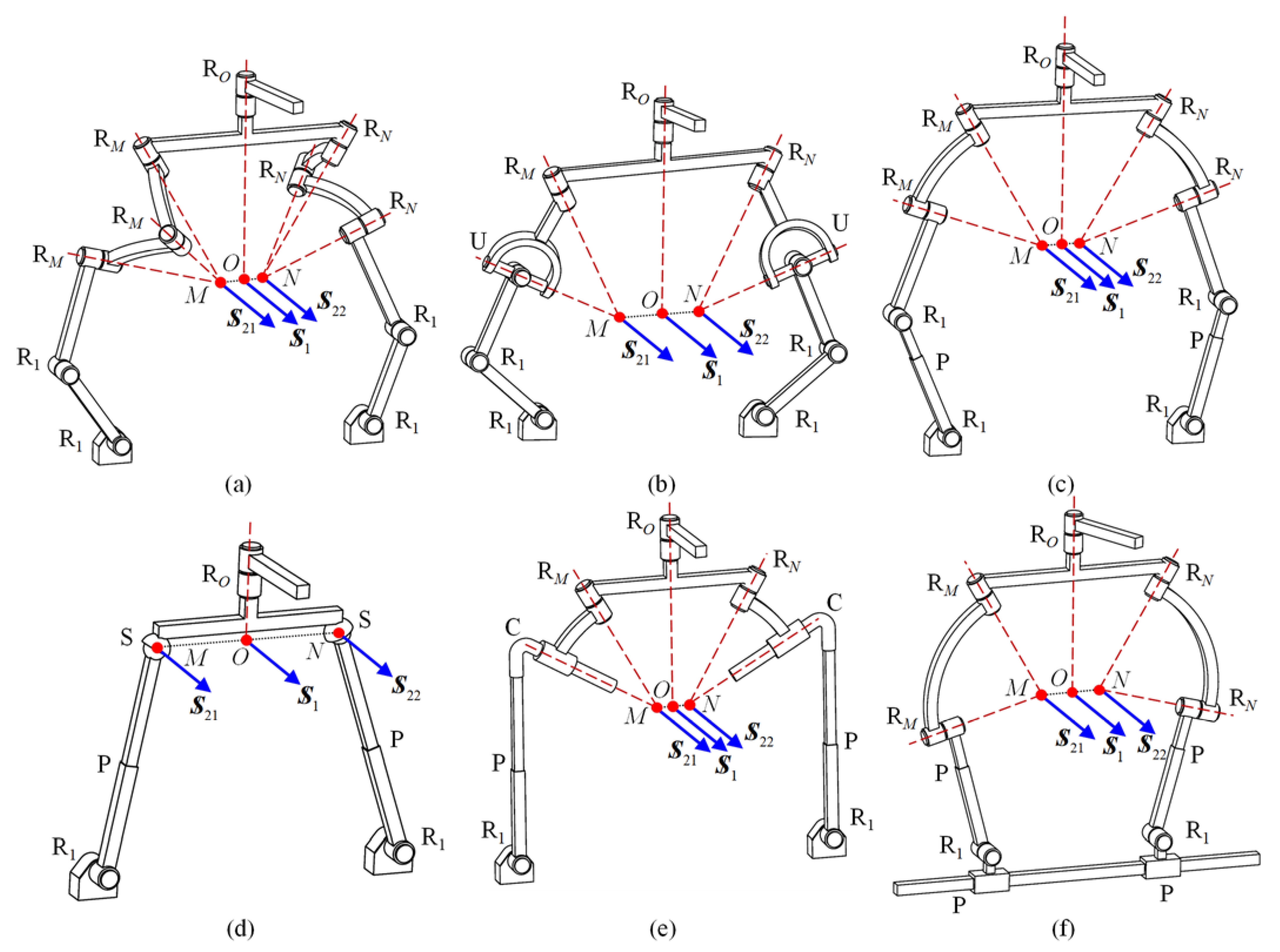
3.2. Synthesis of C-Hybrid Limbs

The constraint provided by the C-hybrid limbs is a constraint couple, which is represented by
S 2 = [ 0 s 2 ]
where unit vector s2 represents the direction of the couple.
If the two subchains generate two constraint couples on the intermediate platform, we can easily reduce them to S 2 by using a revolute joint as the upper chain. This kind of C-hybrid limb was reported by Guo et al. [31].
When the two subchains generate two constraint forces, their directions should be parallel to each other. Otherwise, S 2 cannot be obtained by adding any 1-DOF joint to the intermediate platform. Assuming that the two forces are represented by Equation (3), S 2 should have the same direction as S 23 in Equation (4). To reduce the constraint system S I P 2 to S 2 , the added joint can be either a revolute joint or a prismatic joint.
When a prismatic joint is added, it can be oriented in any direction except perpendicular to s1. When a revolute joint is added, its axis should be parallel to MN to ensure that S 2 will be generated. A class of C-hybrid limbs can be constructed, as shown in Table 3.
In Table 3, RMN denotes a revolute joint whose axis is parallel to vector MN. Figure 5 shows some typical C-hybrid limbs in this class. Note that the hollow blue arrows in Figure 5 represent constraint couple screws with infinite pitch, while the solid blue arrows represent constraint force screws with zero pitch.

4. Construction of 4-DOF PMs

Section 3 presented the synthesis of several classes of F-hybrid limbs and C-hybrid limbs. In Section 4, non-overconstrained 4-DOF PMs will be constructed, including the 3R1T PMs, the 2R2T PMs, and the 1R3T PMs.

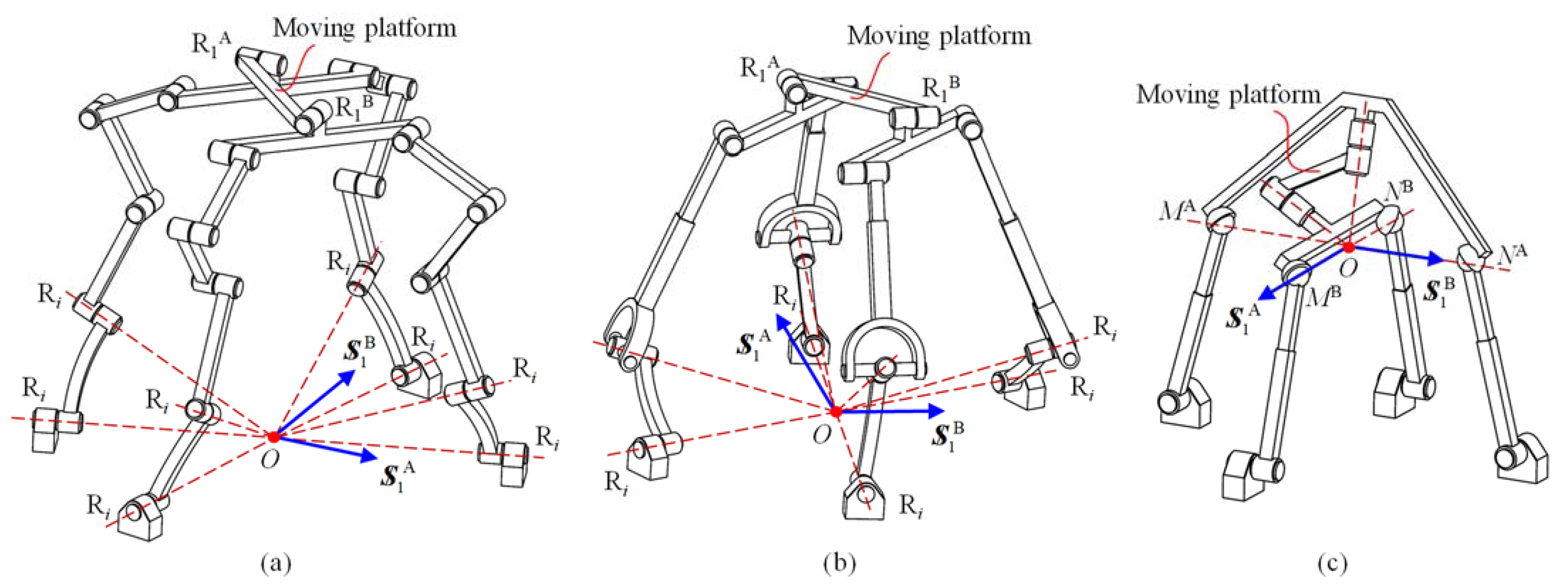
4.1. 3R1T Non-Overconstrained PMs

Clearly, 3R1T non-overconstrained PMs should be constructed using two F-hybrid limbs. Each limb exerts one constraint force on the moving platform, and the two constraint forces should intersect at a common point, which restricts the two translational DOFs of the moving platform. Following these conditions, many non-overconstrained 3R1T PMs can be constructed. Figure 6 shows some typical examples.
Figure 6a shows a PM formed by two [RiRiR11R11R11-RiRiR12R12R12]-R1 hybrid limbs. Since the two R1 joint axes in the two limbs have different directions, they are denoted R1A and R1B. All the Ri joints intersect at a common point O. The two hybrid limbs exert two constraint forces S 1 A and S 1 B on the moving platform. Two translational DOFs are constrained, and the PM has 3R1T DOFs. Similarly, the 2([RiUPR11-RiUPR12]-R1) PM in Figure 6b is also a 3R1T mechanism. For the PM formed by two [R1PS-R1PS]-ROhybrid limbs in Figure 6c, the two RO joint axes intersect at a common point O, which is also the intersection point of lines MANA and MBNB. The moving platform of the PM has three rotational DOFs around point O and one translational DOF along the direction perpendicular to the plane formed by S 1 A and S 1 B . The interesting 3R1T PM proposed by Song et al. [36] can be regarded as a special variation of the PM in Figure 6c.
According to the Grübler/Kutzbach criterion, the DOFs of a mechanism can be calculated as
M = 6 ( n g 1 ) + i = 1 g f i
where n denotes the number of links, g is the number of joints, and fi is the DOFs of the ith joint. For the PM in Figure 6a, n = 20, g = 22, and i = 1 g f i = 22. We can obtain M 4. Similarly, the PMs in Figure 6b,c have 4 DOFs. The constructed 3R1T PMs satisfy the Grübler/Kutzbach criterion, which means they are non-overconstrained PMs.
To reduce the moving mass and maintain a fast dynamic response, it is preferable to mount actuators near the fixed base for PMs. However, some actuators should be mounted far from the fixed base for the PMs in Figure 6. For example, if the four base-connected revolute joints in Figure 6a or b are selected as input joints, the translational DOF of the moving platform will not be controlled. Therefore, only three base-connected revolute joints should be actuated, and the fourth actuator can be mounted to the third revolute joint in an arbitrary subchain. As a result, the translational DOF of this PM is fully determined by the fourth actuator and decoupled from the other DOFs. To verify the actuation scheme for a PM, one can calculate its DOF number with all the actuated joints locked. If the result is zero, the actuation scheme is valid. The proposed 3R1T PMs can be used as a visual tracking device. Once a camera is mounted on the moving platform, we can adjust not only its orientation but also its distance from the target object.

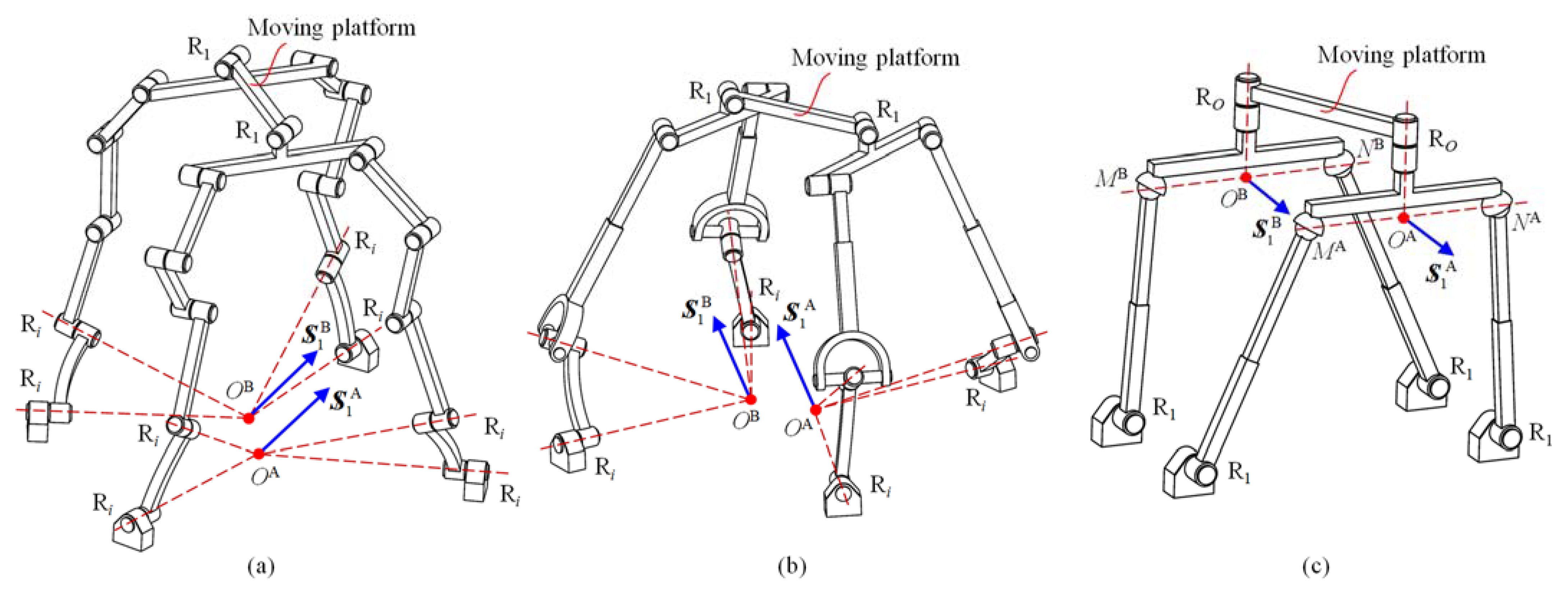
4.2. 2R2T Non-Overconstrained PMs

2R2T non-overconstrained PMs should also be constructed using two F-hybrid limbs. Each limb exerts one constraint force on the moving platform, and the two constraint forces should be parallel to each other, which restricts a translational DOF along the force direction, as well as a rotational DOF around the normal of the plane formed by the two forces. Following these conditions, many non-overconstrained 2R2T PMs can be constructed. Some typical examples are shown in Figure 7.
In Figure 7a, the two R1 joint axes are parallel to each other. Therefore, the two constraint forces S 1 A and S 1 B are also parallel. They pass through points OA and OB, which are determined by the Ri joints in the two hybrid limbs. For the PM in Figure 7c, S 1 A passes through point OA and S 1 B passes through point OB; they are parallel to each other since the R1 joints are parallel. All the PMs in Figure 7 have 2R2T DOFs, and they are non-overconstrained PMs since the Grübler/Kutzbach criterion is satisfied.
Some of the 2R2T PMs in Figure 7 also have the feature of decoupled motion. For example, at least one of the actuators should be mounted to the third revolute joint in a subchain of the PM in Figure 7a. As a result, a translational DOF of the PM is decoupled from the other DOFs. The proposed 2R2T PMs can be used for automated fiber placement [37].

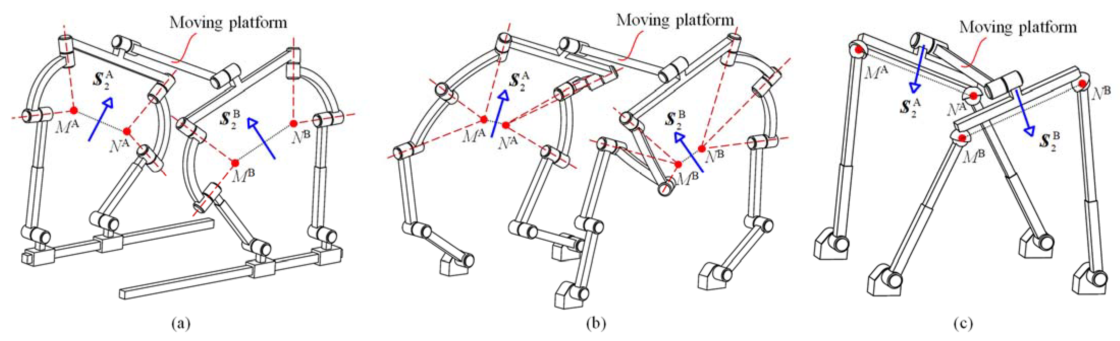
4.3. 1R3T Non-Overconstrained PMs

Constructed by two C-hybrid limbs, Guo et al. proposed a class of 1R3T non-overconstrained PMs [31]. However, different from those structures, in this paper, a new class of C-hybrid limbs is presented whose two subchains both provide constraint force. Using the newly invented C-hybrid limbs, many 1R3T non-overconstrained PMs can be constructed. The only condition for assembling the PMs is that the two constraint couples provided by the C-hybrid limbs should be independent of each other. Some typical examples are shown in Figure 8.
The PMs in Figure 8 are constructed using two C-hybrid limbs. Each limb exerts one constraint couple on the moving platform. The two constraint couples, S 2 A and S 2 B , have different directions, which restrict the two rotational DOFs. Therefore, all the PMs have one rotational and three translational DOFs. Their non-overconstrained characteristic can be verified using the Grübler/Kutzbach criterion.
It is possible to arrange all the actuations near the base for the proposed 1R3T PMs. For example, the four prismatic joints can be selected for the actuation of the PM in Figure 8c. The rotational DOF of the PM is parallel to the R1 joints. The proposed 1R3T PMs can be used in the field of automatic loading and unloading that moves the target object from one position to the other while simultaneously adjusting the posture around one axis.

5. Conclusions

This paper presents the type synthesis of 4-DOF non-overconstrained PMs with symmetrical structures. The PMs have a special topological structure whose moving platform is connected to the fixed base through two hybrid limbs. Each hybrid limb is composed of an upper chain, an intermediate platform, and two subchains. Constraint conditions for 3R1T, 2R2T, and 1R3T symmetrical PMs were analyzed. Hybrid limb structures that can generate a constraint force or a constraint couple were synthesized using screw theory. Three classes of novel PMs with symmetrical structures were constructed, including 3R1T, 2R2T, and 1R3T PMs, which are presented for the first time to our knowledge. The DOF calculation based on the Grübler/Kutzbach criterion demonstrated that the proposed PMs are non-overconstrained mechanisms. The proposed method provides a reference for reducing the number of redundant constraints in other types of PMs, such as 5-DOF PMs.

Author Contributions

Conceptualization, W.Y. and Q.L.; methodology, W.Y.; software, X.C.; validation, W.Y., Q.L. and X.C.; formal analysis, W.Y.; investigation, W.Y.; resources, X.C.; data curation, W.Y.; writing—original draft preparation, W.Y.; writing—review and editing, W.Y.; visualization, W.Y.; supervision, Q.L.; project administration, Q.L.; funding acquisition, Q.L. All authors have read and agreed to the published version of the manuscript.

Funding

This research was funded by the Open Foundation of The State Key Laboratory of Mechanical Transmissions, Chongqing University under grant number SKLMT-ZDKFKT-202002, and the National Natural Science Foundation of China (NSFC) under grant number 51935010.

Data Availability Statement

Not applicable.

Conflicts of Interest

The authors declare no conflict of interest.

References

  1. Pierrot, F.; Reynaud, C.; Fournier, A. DELTA: A simple and efficient parallel robot. Robotica 1990, 8, 105–109. [Google Scholar] [CrossRef]
  2. Gasparetto, A.; Scalera, L. From the Unimate to the Delta robot: The early decades of Industrial Robotics. In Explorations in the History and Heritage of Machines and Mechanisms; Springer: Berlin/Heidelberg, Germany, 2019; pp. 284–295. [Google Scholar]
  3. Hunt, K.H. Structural kinematics of in-parallel-actuated robot-arms. J. Mech. Transm. Autom. Des. 1983, 105, 705–712. [Google Scholar] [CrossRef]
  4. Ma, Y.; Tian, Y.; Song, Y. A Screw Theory-Based Approach for Conservative Stiffness Mapping of 3-PRS Parallel Mechanism. In 2022 WRC Symposium on Advanced Robotics and Automation (WRC SARA); IEEE: Beijing, China, 2022; pp. 19–24. [Google Scholar]
  5. Pierrot, F.; Krut, S.; Nabat, V. Four-Dof PKM with articulated travelling-plate. In Proceedings of the Parallel Kinematics Seminar, Chemnitz, Germany, 25–26 April 2006; pp. 25–26. [Google Scholar]
  6. Liu, Y.; Kong, M.; Wan, N.; Ben-Tzvi, P. A Geometric Approach to Obtain the Closed-Form Forward Kinematics of H4 Parallel Robot. J. Mech. Robot. 2018, 10, 051013. [Google Scholar] [CrossRef] [Green Version]
  7. Fang, Y.; Tsai, L.W. Structure synthesis of a class of 4-DoF and 5-DoF parallel manipulators with identical limb structures. Int. J. Robot. Res. 2002, 21, 799–810. [Google Scholar] [CrossRef]
  8. Tsai, L.W. Systematic enumeration of parallel manipulators. In Parallel Kinematic Machines; Springer: London, UK, 1999; pp. 33–49. [Google Scholar]
  9. Huang, Z.; Li, Q.C. General methodology for type synthesis of symmetrical lower-mobility parallel manipulators and several novel manipulators. Int. J. Robot. Res. 2002, 21, 131–145. [Google Scholar] [CrossRef]
  10. Huang, Z.; Li, Q.C. Type Synthesis of Symmetrical Lower-Mobility Parallel Mechanisms Using the Constraint-Synthesis Method. Int. J. Robot. Res. 2003, 22, 59–79. [Google Scholar] [CrossRef]
  11. Kong, X.; Gosselin, C.M. Type synthesis of 3T1R 4-DOF parallel manipulators based on screw theory. IEEE Trans. Robot. Autom. 2004, 20, 181–190. [Google Scholar] [CrossRef]
  12. Kong, X.; Gosselin, C.M. Type synthesis of 5-DOF parallel manipulators based on screw theory. J. Robot. Syst. 2005, 22, 535–547. [Google Scholar] [CrossRef]
  13. Kong, X.; Gosselin, C.M. Type synthesis of 4-DOF SP-equivalent parallel manipulators: A virtual chain approach. Mech. Mach. Theory 2006, 41, 1306–1319. [Google Scholar] [CrossRef]
  14. Meng, X.; Gao, F.; Wu, S.; Ge, Q.J. Type synthesis of parallel robotic mechanisms: Framework and brief review. Mech. Mach. Theory 2014, 78, 177–186. [Google Scholar] [CrossRef]
  15. Xie, F.; Li, T.; Liu, X. Type synthesis of 4-DOF parallel kinematic mechanisms based on Grassmann line geometry and atlas method. Chin. J. Mech. Eng. 2013, 26, 1073–1081. [Google Scholar] [CrossRef]
  16. Xie, F.; Liu, X.J. Design and development of a high-speed and high-rotation robot with four identical arms and a single platform. J. Mech. Robot. 2015, 7, 041015. [Google Scholar] [CrossRef]
  17. Li, Q.; Hervé, J.M.; Ye, W. Geometric Method for Type Synthesis of Parallel Manipulators; Springer: Singapore, 2020. [Google Scholar]
  18. Zhao, T.S.; Dai, J.S.; Huang, Z. Geometric Analysis of Overconstrained Parallel Manipulators with Three and Four Degrees of Freedom. JSME Int. J. Ser. C 2002, 45, 730–740. [Google Scholar] [CrossRef] [Green Version]
  19. Guo, S.; Wang, C.; Qu, H.; Fang, Y. A novel 4-RRCR parallel mechanism based on screw theory and its kinematics analysis. Proc. Inst. Mech. Eng. Part C J. Mech. Eng. Sci. 2013, 227, 2039–2048. [Google Scholar] [CrossRef]
  20. Amine, S.; Masouleh, M.T.; Caro, S.; Wenger, P.; Gosselin, C.M. Singularity Conditions of 3T1R Parallel Manipulators With Identical Limb Structures. J. Mech. Robot. 2012, 4, 011011. [Google Scholar] [CrossRef] [Green Version]
  21. Masouleh, M.T.; Gosselin, C.; Husty, M.; Walter, D.R. Forward kinematic problem of 5-RPUR parallel mechanisms (3T2R) with identical limb structures. Mech. Mach. Theory 2011, 46, 945–959. [Google Scholar] [CrossRef]
  22. Cao, W.; Ding, H. A method for solving all joint reactions of 3R2T parallel mechanisms with complicated structures and mul-tiple redundant constraints. Mech. Mach. Theory 2018, 121, 718–730. [Google Scholar] [CrossRef]
  23. Zhu, S.-J.; Huang, Z. Eighteen fully symmetrical 5-DoF 3R2T parallel manipulators with better actuating modes. Int. J. Adv. Manuf. Technol. 2007, 34, 406–412. [Google Scholar] [CrossRef]
  24. Dai, J.S.; Huang, Z.; Lipkin, H. Mobility of overconstrained parallel mechanisms. J. Mech. Des. 2006, 128, 220–229. [Google Scholar] [CrossRef]
  25. Fang, Y.; Tsai, L.W. Enumeration of a class of overconstrained mechanisms using the theory of reciprocal screws. Mech. Mach. Theory 2004, 39, 1175–1187. [Google Scholar] [CrossRef]
  26. Gan, D.; Dai, J.S. Geometry constraint and branch motion evolution of 3-PUP parallel mechanisms with bifurcated motion. Mech. Mach. Theory 2013, 61, 168–183. [Google Scholar] [CrossRef]
  27. Zhang, K.; Dai, J.S.; Fang, Y. Constraint analysis and bifurcated motion of the 3PUP parallel mechanism. Mech. Mach. Theory 2012, 49, 256–269. [Google Scholar] [CrossRef]
  28. Ruggiu, M.; Kong, X. Mobility and kinematic analysis of a parallel mechanism with both PPR and planar operation modes. Mech. Mach. Theory 2012, 55, 77–90. [Google Scholar] [CrossRef]
  29. Kong, X.; Yu, J. Type Synthesis of Two-Degrees-of-Freedom 3-4R Parallel Mechanisms With Both Spherical Translation Mode and Sphere-on-Sphere Rolling Mode. J. Mech. Robot. 2015, 7, 041018. [Google Scholar] [CrossRef]
  30. Krut, S.; Benoit, M.; Ota, H.; Pierrot, F. I4: A new parallel mechanism for Scara motions. In 2003 IEEE International Conference on Robotics and Automation (Cat. No. 03CH37422); IEEE: Taipei, Taiwan, 2003; Volume 2, pp. 1875–1880. [Google Scholar]
  31. Guo, S.; Fang, Y.; Qu, H. Type synthesis of 4-DOF nonoverconstrained parallel mechanisms based on screw theory. Robotica 2012, 30, 31–37. [Google Scholar] [CrossRef]
  32. Sun, T.; Song, Y.; Gao, H.; Qi, Y. Topology Synthesis of a 1-Translational and 3-Rotational Parallel Manipulator with an Articulated Traveling Plate. J. Mech. Robot. 2015, 7, 31015. [Google Scholar] [CrossRef]
  33. He, J.; Gao, F.; Meng, X.; Guo, W. Type synthesis for 4-DOF parallel press mechanism using GF set theory. Chin. J. Mech. Eng. 2015, 28, 851–859. [Google Scholar] [CrossRef]
  34. Murray, R.C.; Ophaswongse, C.; Agrawal, S.K. Design of a wheelchair robot for active postural support. J. Mech. Robot. 2019, 11, 020911. [Google Scholar] [CrossRef]
  35. Wang, G.; Wang, L. Dynamics investigation of spatial parallel mechanism considering rod flexibility and spherical joint clearance. Mech. Mach. Theory 2019, 137, 83–107. [Google Scholar] [CrossRef]
  36. Song, Y.; Gao, H.; Sun, T.; Dong, G.; Lian, B.; Qi, Y. Kinematic analysis and optimal design of a novel 1T3R parallel manipulator with an articulated travelling plate. Robot. Comput. Manuf. 2014, 30, 508–516. [Google Scholar] [CrossRef]
  37. Gan, D.; Dai, J.S.; Dias, J.; Umer, R.; Seneviratne, L. Singularity-Free Workspace Aimed Optimal Design of a 2T2R Parallel Mechanism for Automated Fiber Placement. J. Mech. Robot. 2015, 7, 041022. [Google Scholar] [CrossRef]
Figure 1. Topological structure of a non-overconstrained 4-DOF PM.
Machines 10 01123 g001
Figure 2. Structure of the hybrid limb.
Machines 10 01123 g002
Figure 3. Typical F-hybrid limbs in the first class: (a) [RiRiR11R11R11-RiRiR12R12R12]-R1, (b) [RiRiRiR11R11-RiRiRiR12R12]-P, (c) [RiUPR11-RiUPR12]-R1, (d) [RiRiCR11-RiRiCR12]-P, (e) [RiCPR11-RiCPR12]-R1, (f) [RiRiPPR11-RiRiPPR12]-P.
Machines 10 01123 g003
Figure 4. Typical F-hybrid limbs in the second class: (a) [R1R1RMRMRM-R1R1RNRNRN]-RO, (b) [R1R1URM-R1R1URN]-RO, (c) [R1PR1RMRM-R1PR1RNRN]-RO, (d) [R1PS-R1PS]-RO, (e) [R1PCRM-R1PCRN]-RO, (f) [PR1PRMRM-PR1PRNRN]-RO.
Machines 10 01123 g004
Figure 5. Typical C-hybrid limbs: (a) [R1R1RMRMRM-R1R1RNRNRN]-RMN, (b) [R1R1URM-R1R1URN]-P, (c) [R1PR1RMRM-R1PR1RNRN]-P, (d) [R1PS-R1PS]-RMN, (e) [R1PCRM-R1PCRN]-P, (f) [PR1PRMRM-PR1PRNRN]-RMN.
Machines 10 01123 g005
Figure 6. Typical non-overconstrained 3R1T PMs: (a) 2([RiRiR11R11R11-RiRiR12R12R12]-R1) PM, (b) 2([RiUPR11-RiUPR12]-R1) PM, (c) 2([R1PS-R1PS]-RO) PM.
Machines 10 01123 g006
Figure 7. Typical non-overconstrained 2R2T PMs: (a) 2([RiRiR11R11R11-RiRiR12R12R12]-R1) PM, (b) 2([RiUPR11-RiUPR12]-R1) PM, (c) 2([R1PS-R1PS]-RO) PM.
Machines 10 01123 g007
Figure 8. Typical non-overconstrained 1R3T PMs: (a) 2([PR1PRMRM-PR1PRNRN]-RMN) PM, (b) 2([R1R1RMRMRM-R1R1RNRNRN]-RMN) PM, (c) 2([R1PS-R1PS]-RMN) PM.
Machines 10 01123 g008
Table 1. The first class of F-hybrid limbs.
Limb TypeLimb with Single-DOF JointsLimb with Composite Joints
[5R-5R]-R[RiRiRiR11R11-RiRiRiR12R12]-R1[RiRiUR11-RiRiUR11]-R1
[RiRiR11R11R11-RiRiR12R12R12]-R1[RiUR11R11-RiUR11R11]-R1
[5R-5R]-P[RiRiRiR11R11-RiRiRiR12R12]-P[RiRiUR11-RiRiUR11]-P
[RiRiR11R11R11-RiRiR12R12R12]-P[RiUR11R11-RiUR11R11]-P
[4R1P-4R1P]-R[RiRiRiR11P-RiRiRiR12P]-R1[RiRiUP-RiRiUP]-R1
[RiRiRiPR11-RiRiRiPR12]-R1[RiRiCR11-RiRiCR12]-R1
[RiRiR11R11P-RiRiR12R12P]-R1[RiUR11P-RiUR12P]-R1
[RiRiR11PR11-RiRiR12PR12]-R1[RiUPR11-RiUPR12]-R1
[RiRiPR11R11-RiRiPR12R12]-R1[RiCR11R11-RiCR12R12]-R1
[4R1P-4R1P]-P[RiRiRiR11P-RiRiRiR12P]-P[RiRiUP-RiRiUP]-P
[RiRiRiPR11-RiRiRiPR12]-P[RiRiCR11-RiRiCR12]-P
[RiRiR11R11P-RiRiR12R12P]-P[RiUR11P-RiUR12P]-P
[RiRiR11PR11-RiRiR12PR12]-P[RiUPR11-RiUPR12]-P
[RiRiPR11R11-RiRiPR12R12]-P[RiCR11R11-RiCR12R12]-P
[3R2P-3R2P]-R[RiRiRiPP-RiRiRiPP]-R1[RiRiCP-RiRiCP]-R1
[RiRiR11PP-RiRiR12PP]-R1[RiUPP-RiUPP]-R1
[RiRiPPR11-RiRiPPR12]-R1[RiCPR11-RiCPR12]-R1
[RiRiPR11P-RiRiPR12P]-R1[RiCR11P-RiCR12P]-R1
[3R2P-3R2P]-P[RiRiRiPP-RiRiRiPP]-P[RiRiCP-RiRiCP]-P
[RiRiR11PP-RiRiR12PP]-P[RiUPP-RiUPP]-P
[RiRiPPR11-RiRiPPR12]-P[RiCPR11-RiCPR12]-P
[RiRiPR11P-RiRiPR12P]-P[RiCR11P-RiCR12P]-P
Table 2. The second class of F-hybrid limbs.
Limb TypeLimb with Single-DOF JointsLimb with Composite Joints
[5R-5R]-R[R1R1RMRMRM-R1R1RNRNRN]-RO
[R1R1R1RMRM-R1R1R1RNRN]-RO
[R1URMRM-R1URNRN]-RO
[R1R1URM-R1R1URN]-RO
[R1R1S-R1R1S]-RO
[4R1P-4R1P]-R[R1PRMRMRM-R1PRNRNRN]-RO
[PR1RMRMRM-PR1RNRNRN]-RO
[PR1R1RMRM-PR1R1RNRN]-RO
[R1PR1RMRM-R1PR1RNRN]-RO
[R1R1PRMRM-R1R1PRNRN]-RO
[R1CRMRM-R1CRNRN]-RO
[PURMRM-PURNRN]-RO
[PR1URM-PR1URN]-RO
[R1PURM-R1PURN]-RO
[R1R1CRM-R1R1CRN]-RO
[R1PS-R1PS]-RO
[PR1S-PR1S]-RO
[3R2P-3R2P]-R[PPRMRMRM-PPRNRNRN]-RO
[PPR1RMRM-PPR1RNRN]-RO
[R1PPRMRM-R1PPRNRN]-RO
[PR1PRMRM-PR1PRNRN]-RO
[PCRMRM-PCRNRN]-RO
[PPURM-PPURN]-RO
[R1PCRM-R1PCRN]-RO
[PR1CRM-PR1CRN]-RO
[PPS-PPS]-RO
Table 3. A class of C-hybrid limbs.
Limb TypeLimb with Single-DOF JointsLimb with Composite Joints
[5R-5R]-R[R1R1RMRMRM-R1R1RNRNRN]-RMN
[R1R1R1RMRM-R1R1R1RNRN]-RMN
[R1URMRM-R1URNRN]-RMN
[R1R1URM-R1R1URN]-RMN
[R1R1S-R1R1S]-RMN
[5R-5R]-P[R1R1RMRMRM-R1R1RNRNRN]-P
[R1R1R1RMRM-R1R1R1RNRN]-P
[R1URMRM-R1URNRN]-P
[R1R1URM-R1R1URN]-P
[R1R1S-R1R1S]-P
[4R1P-4R1P]-R[R1PRMRMRM-R1PRNRNRN]-RMN
[PR1RMRMRM-PR1RNRNRN]-RMN
[PR1R1RMRM-PR1R1RNRN]-RMN
[R1PR1RMRM-R1PR1RNRN]-RMN
[R1R1PRMRM-R1R1PRNRN]-RMN
[R1CRMRM-R1CRNRN]-RMN
[PURMRM-PURNRN]-RMN
[PR1URM-PR1URN]-RMN
[R1PURM-R1PURN]-RMN
[R1R1CRM-R1R1CRN]-RMN
[R1PS-R1PS]-RMN
[PR1S-PR1S]-RMN
[4R1P-4R1P]-P[R1PRMRMRM-R1PRNRNRN]-P
[PR1RMRMRM-PR1RNRNRN]-P
[PR1R1RMRM-PR1R1RNRN]-P
[R1PR1RMRM-R1PR1RNRN]-P
[R1R1PRMRM-R1R1PRNRN]-P
[R1CRMRM-R1CRNRN]-P
[PURMRM-PURNRN]-P
[PR1URM-PR1URN]-P
[R1PURM-R1PURN]-P
[R1R1CRM-R1R1CRN]-P
[R1PS-R1PS]-P
[PR1S-PR1S]-P
[3R2P-3R2P]-R[PPRMRMRM-PPRNRNRN]-RMN
[PPR1RMRM-PPR1RNRN]-RMN
[R1PPRMRM-R1PPRNRN]-RMN
[PR1PRMRM-PR1PRNRN]-RMN
[PCRMRM-PCRNRN]-RMN
[PPURM-PPURN]-RMN
[R1PCRM-R1PCRN]-RMN
[PR1CRM-PR1CRN]-RMN
[PPS-PPS]-RMN
[3R2P-3R2P]-P[PPRMRMRM-PPRNRNRN]-P
[PPR1RMRM-PPR1RNRN]-P
[R1PPRMRM-R1PPRNRN]-P
[PR1PRMRM-PR1PRNRN]-P
[PCRMRM-PCRNRN]-P
[PPURM-PPURN]-P
[R1PCRM-R1PCRN]-P
[PR1CRM-PR1CRN]-P
[PPS-PPS]-P
Publisher’s Note: MDPI stays neutral with regard to jurisdictional claims in published maps and institutional affiliations.

