The traditional wing has a large support stiffness to ensure that the wing will not produce large deformations during flight. When the main beam structure of the traditional wing is eliminated, the local stiffness of the wing may decrease. Thus, it is necessary to analyze and simulate the stiffness of the tensegrity structure and the parallel mechanism.
4.1. Stiffness Analysis of Tensegrity Structure
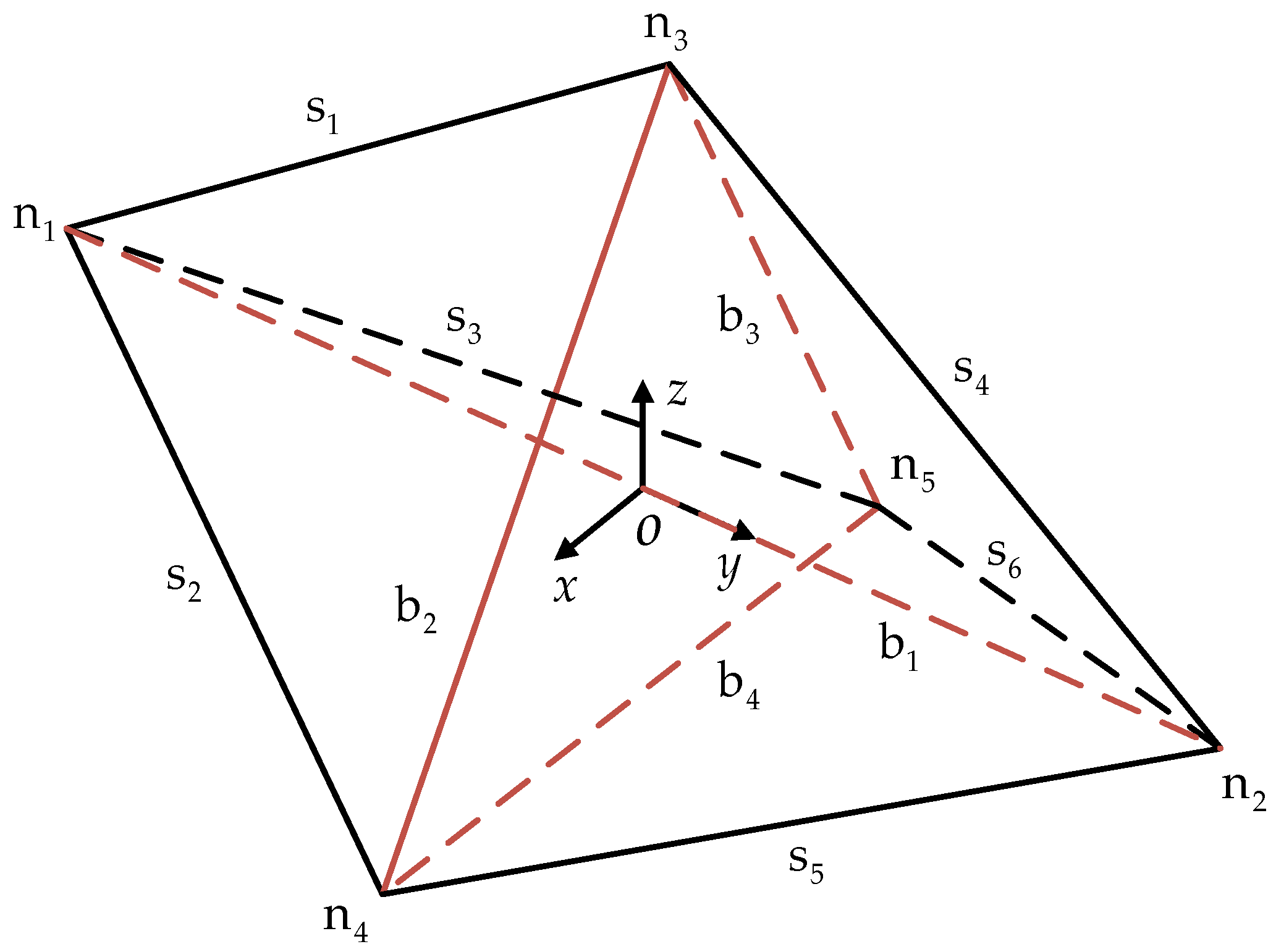
The node position of the tensegrity structure is shown in
Figure 1. The angle between the projection of the connection line from node n
1 to node n
2 in the
x-o-y plane and the positive direction of the
y-axis is denoted as
. The unit vector of all components can be obtained from the node coordinates and connection matrix. The internal forces of each component are denoted as
fsi and
fbj. Then, the force at the nodes n
3 and n
4 caused by rod b
2 is obtained as:
where a denotes the length of rigid rod
b2, and
denotes the force density value of rigid rod
b2.
The tangent stiffness matrix is constructed, and the node force component is derived from the node coordinate:
where
represents the component of the force at position
n3 of the node caused by rigid rod
b2 in direction
i;
represents the component of the force at position
n4 of the node caused by rigid rod b
2 in direction
i;
represents the coordinate component of node
n3 in direction
j;
represents the coordinate component of node
n4 in direction
j.
When
i =
j,
δij = 1;
i ≠
j,
δij = 0. Through simplification, the following formula can be obtained:
According to the definition of tensile strength, we have:
where
Ab2 represents the cross-sectional area of rigid rod
b2, and
Eb2 denotes Young’s Modulus of rigid rod
b2. Then, the following formula can be obtained:
For rigid rod
b2, the relationship between the small change in the displacement at the node position and the small change in the force at the node position can be obtained based on the tangent stiffness matrix:
The tangential stiffness matrix of rigid rod b2 is obtained. Then, the tangential stiffness matrix of all components can be obtained through this deduction. The tangent stiffness matrix KS of the trigonal bipyramidal tensegrity structure is obtained by combining the tangent stiffness matrix of all components.
The active tensegrity structure is connected with the wing morphing mechanism through nodes n1, n2 and n3. Since it is assumed that the wing morphing mechanism will not deform at n1, n2 and n3, the tangent stiffness matrix is set to 1 at the diagonal position of lines 1, 2, 3, 7, 8, 9, 10, 11, 12, and the tangent stiffness matrix at other positions is set to 0. Based on this, the stiffness matrix under the initial boundary condition is obtained.
The main materials of aircraft wing bearing structure are 7075 aviation aluminum alloy and structural steel. Therefore, the influence of the two materials on stiffness was studied. The specific parameters of the 7075 aviation aluminum alloy are presented in
Table 4.
Since there is no parameter selection for flexible cables in ANSYS, the existing Cable280 element was adopted to simulate the flexible cable. The material is structural steel. The specific parameters of the Cable280 unit are presented in
Table 5.
The sectional area of the rigid rob is Ab1 = 78.5 mm2, Ab2 = Ab3 = Ab4 = 50.3 mm2. The sectional area of the flexible cable is As1 = As2 = As3 = As4 = As5 = As6 = 7.1 mm2. The length of the rigid rod and flexible cable can be obtained by the geometric relation. The internal force density ratio of each component is , so fb1 = 1470 N, fb2 = 600 N and fb3 = 400 N. The rigid rod is compressed, and the flexible cable is pulled. Given a force of 100 N along the z-axis at node n2, the theoretical deformation at the node n2 and node n5 can be calculated.
When the material is structural steel, the theoretical deformation is:
When the material is 7075 aviation aluminum alloy, the theoretical deformation is:
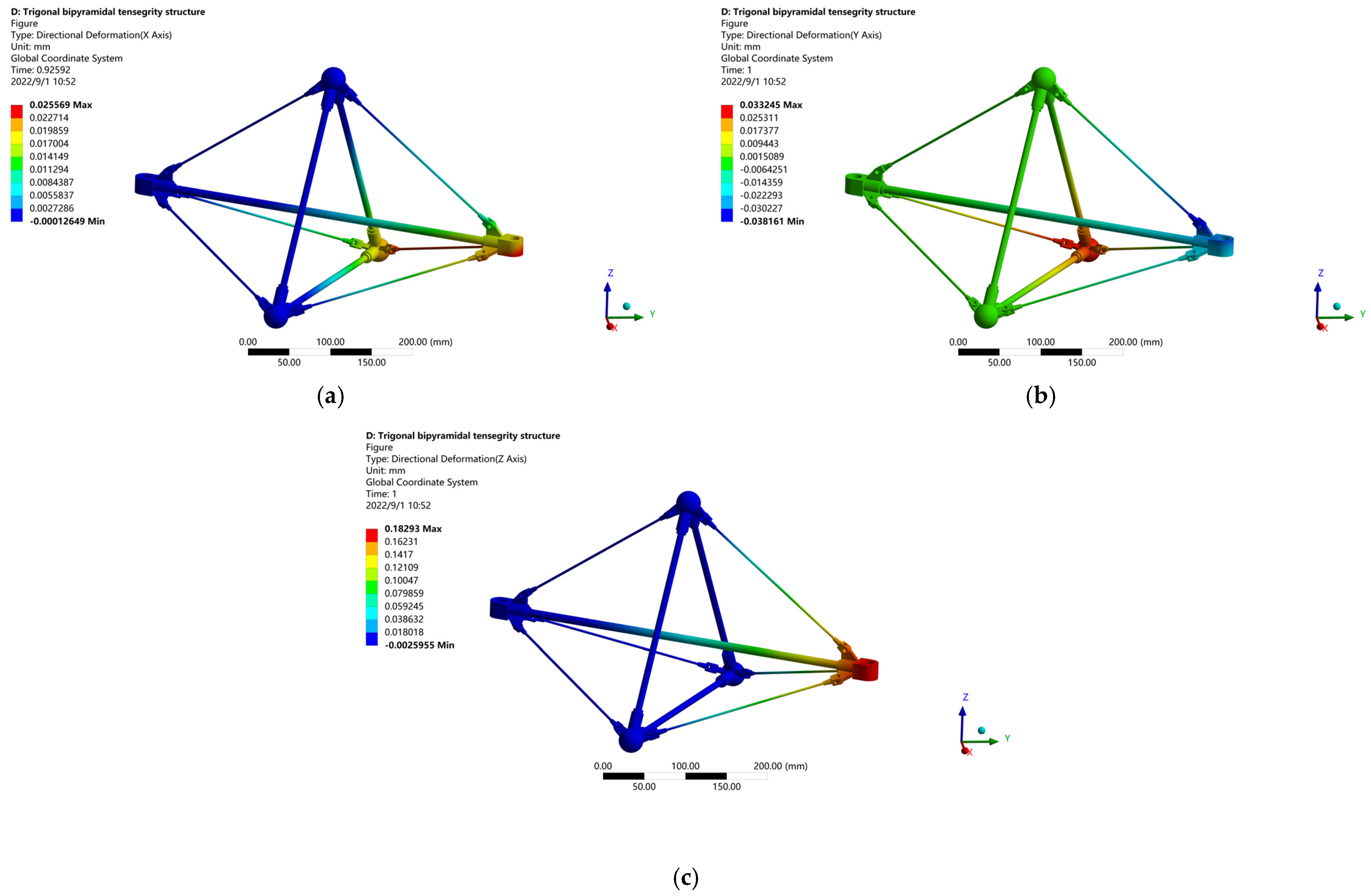
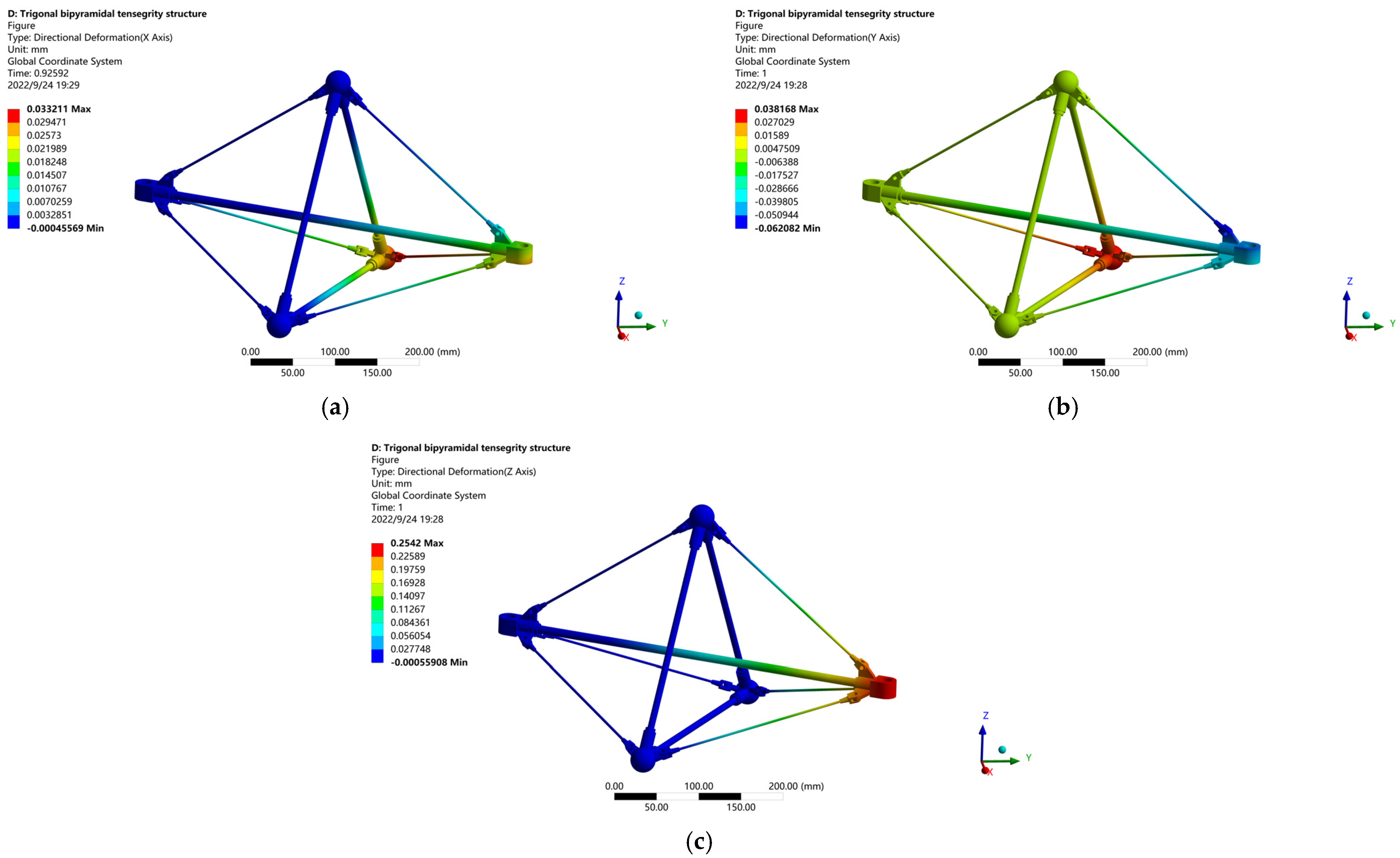
The deformation of each node position is obtained by ANSYS simulation. As shown in
Figure 11 and
Figure 12.
The deformation along the coordinate axis at nodes
n2 and
n5 can be expressed. When the material is structural steel, the simulation deformation is:
When the material is 7075 aviation aluminum alloy, the simulation deformation is:
The above analyzes the influence of two materials on the structural stiffness, when the external load is the same, the deformation of 7075 aviation aluminum alloy is larger than that of structural steel. However, the weight of 7075 aviation aluminum alloy is lighter than that of structural steel. The combination of the two materials is the best option, with high-strength structural steel selected at key connection points and 7075 aviation aluminum alloy used in the wing body.
Due to the optimization design of some structures in the simulation and some meshing errors in the simulation, the deformation of the nodes obtained by the simulation was smaller than that obtained by the theoretical calculation. The average error was within 10%, which verifies the correctness of the stiffness theoretical model.
4.2. Stiffness Analysis of the 4SPS-RS Parallel Mechanism
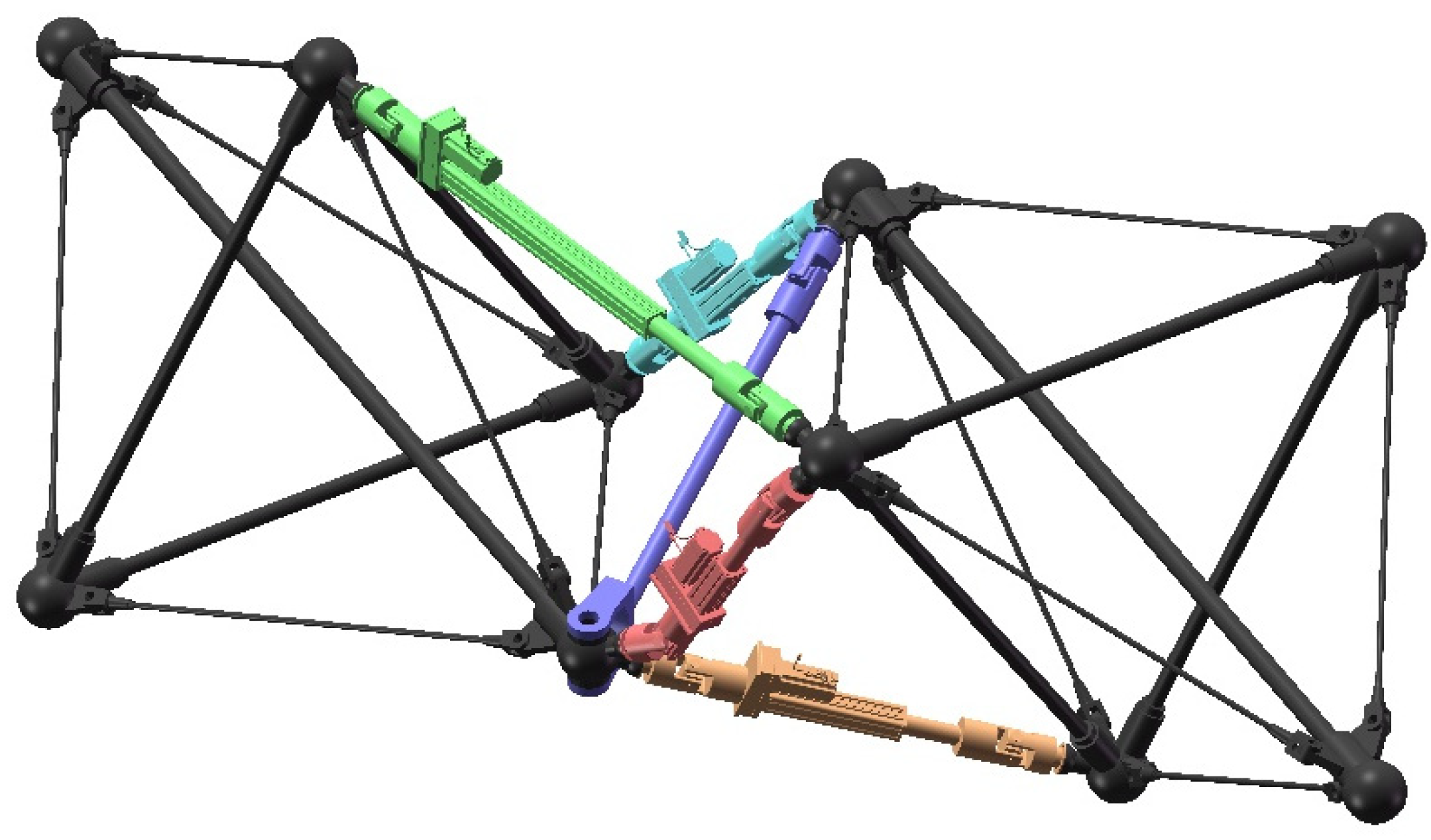
Here, the stiffness analysis model of the wing morphing mechanism is established. If the stiffness of the mechanism is poor, the deformation of the wing may be too large to generate the required lift. Since the analysis focuses on the morphing mechanism of the wing, it is assumed that the tensegrity structure is a rigid body. The influence of joint friction, environment, and other factors is ignored, and only the influence of the driving joint, passive joint and connecting rod on the stiffness of the mechanism is considered. Meanwhile, since SPS is used as the driving branch, the two bars in each branch are force bars, which only carry the load in the direction of the branch axis. Furthermore, in the driving branch, the support stiffness of the spherical pair is large, so its influence on the branch stiffness can be ignored. Thus, it is necessary to analyze the axial stiffness of the drive joint and the connecting rod. In the central branch, the bending and tensile stiffness of the central connecting rod are analyzed.
The drive branch stiffness model is established, and the ball screw is used as the drive, including the axial stiffness of the screw, the ball nut, and the connecting rod:
where
Kg represents the axial stiffness of the screw,
Ag represents the cross-sectional area of the screw,
dg represents the thread diameter of the screw,
Eg represents the elastic model of the screw, and
Lg represents the distance between the load point and the double thrust bearing.
The stiffness analytical formula of the ball nut is obtained by referring to the national standard manual:
where
Km represents the axial stiffness of the ball nut,
im represents the number of ball bearing circles,
Pm represents the ball screw guide,
Em represents the elastic modulus of the ball nut,
represents the contact angle,
Dm1 represents the outer diameter of the ball nut, and
Dm2 represents the diameter of the contact point on the ball nut.
The driving branch consists of two connecting rods. Connecting rod 1 connects the fixed tensegrity structure and the driving joint. It is used as the hollow rod because the internal needs to put the ball screw. Connecting rod 2 connects the active tensegrity structure and driving joint, and is used as the solid rod.
where
d1,
D1 represents the inner and outer diameters of rod 1;
D2 represents the diameter of rod 2;
L1,
L2 represents the lengths of rod 1 and rod 2.
The drive branch stiffness matrix is established as:
The axial tensile stiffness of four driving branches can be calculated as:
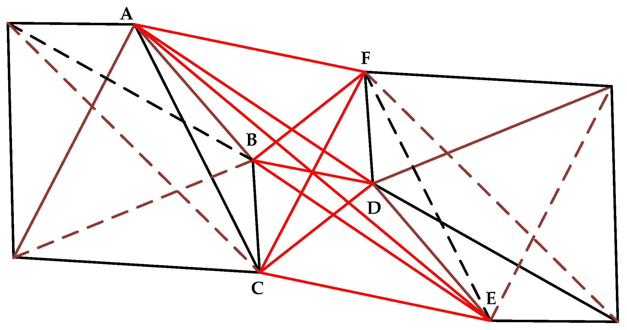
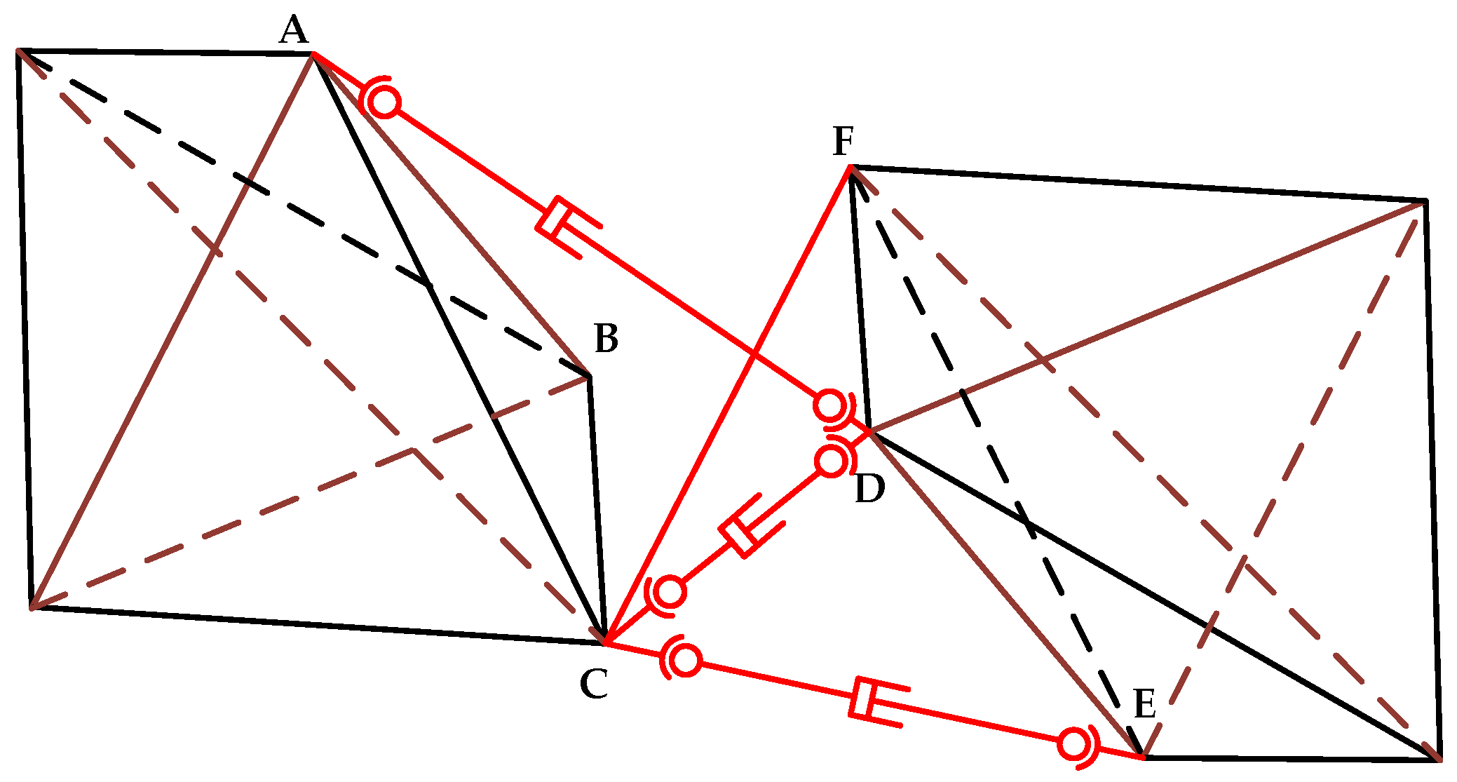
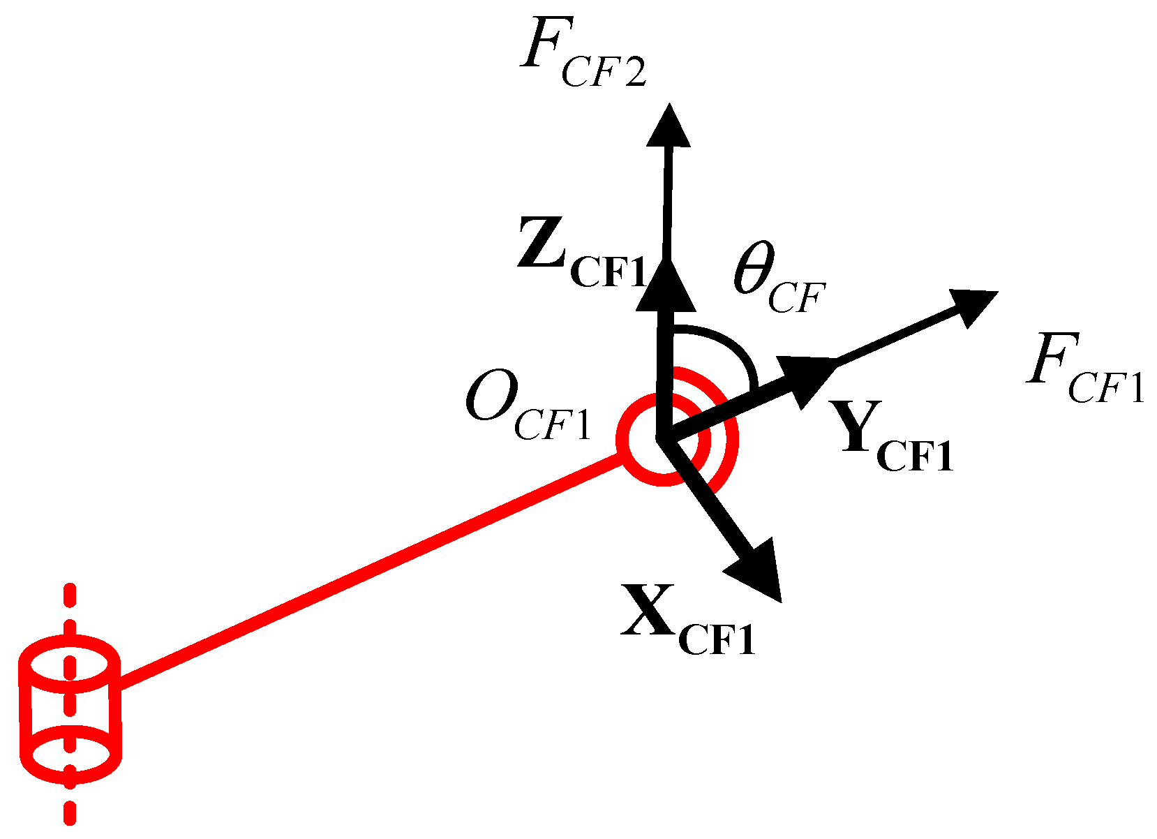
The force analysis of the central connecting rod is carried out. The central branch is constrained by two forces acting on the center of the ball pair. The constraint force
FCF1 is along the direction of the central branch, and the constraint force
FCF2 is parallel to the direction of the rotating pair. The angle between constraint
FCF1 and
FCF2 is denoted as
. The constraint forces of the central branch are shown in
Figure 13.
The constraint force
FCF1 generates tensile deformation on the central rod, so its axial tensile stiffness is obtained as:
The constraint force
FCF2 generates tensile and bending deformation on the central rod. Thus,
generates bending deformation, and
generates tensile and compression deformation. Therefore, the axial stiffness and bending stiffness of the central connecting rod can be calculated as:
where
represents the tensile stiffness of the central connecting rod,
represents the bending stiffness of the central connecting rod, and
represents the moment of inertia of the central connecting rod.
By applying the structural parameters, the stiffness of the central branch is obtained as:
Therefore, the branch stiffness matrix of the wing morphing mechanism can be calculated as:
The stiffness matrix of the wing morphing mechanism is obtained by the Jacobian matrix as:
Then, based on the stiffness theoretical model of the wing morphing mechanism, the mapping relationship between the end position deformation and the external force is obtained. The structural parameters are substituted into the theoretical stiffness model to obtain the theoretical deformation. The force along the z-axis of 100 N is applied to the origin position of the moving coordinate system of the mechanism. ANSYS is employed to simulate the wing morphing mechanism to obtain the simulation deformation at the end position of the mechanism.
When the external load is the force of 100 N along the
z-axis and the material is structural steel, the theoretical deformation is obtained as:
When the external load is the force of 100 N along the
z-axis and the material is 7075 aviation aluminum alloy, the theoretical deformation is obtained as:
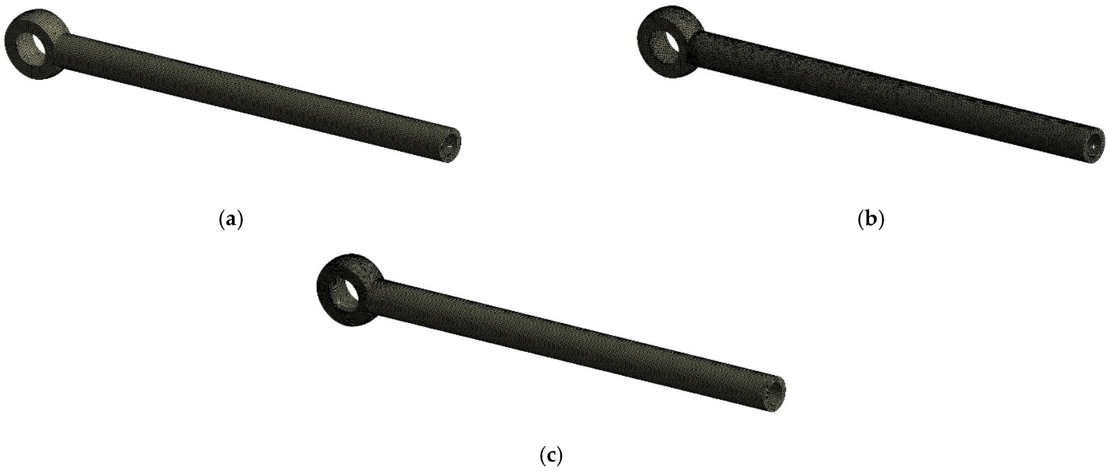
The model was simulated and verified with ANSYS without considering the deformation of the tensegrity structure, so it was set as a rigid body. The rigid rod in the tensegrity structure and the connecting rod in the driving branch of 4SPS-RS parallel mechanism are both two-force rods. Therefore, it was set as the rod unit. Each part is meshed based on tetrahedral, hexahedral and other basic units. By comparing the deformation of 1 mm, 3 mm, 5 mm mesh size, when the mesh size is 1 mm, the deformation will not change greatly. A variety of simulation results were obtained. By comparing the deformation, the three closest meshing methods were obtained. The difference of deformation was within 0.01 mm. The grid can be considered convergent. The NODE point was established at the centroid position of the moving coordinate system, and the deformation was measured to obtain the simulation results. As shown in
Figure 14.
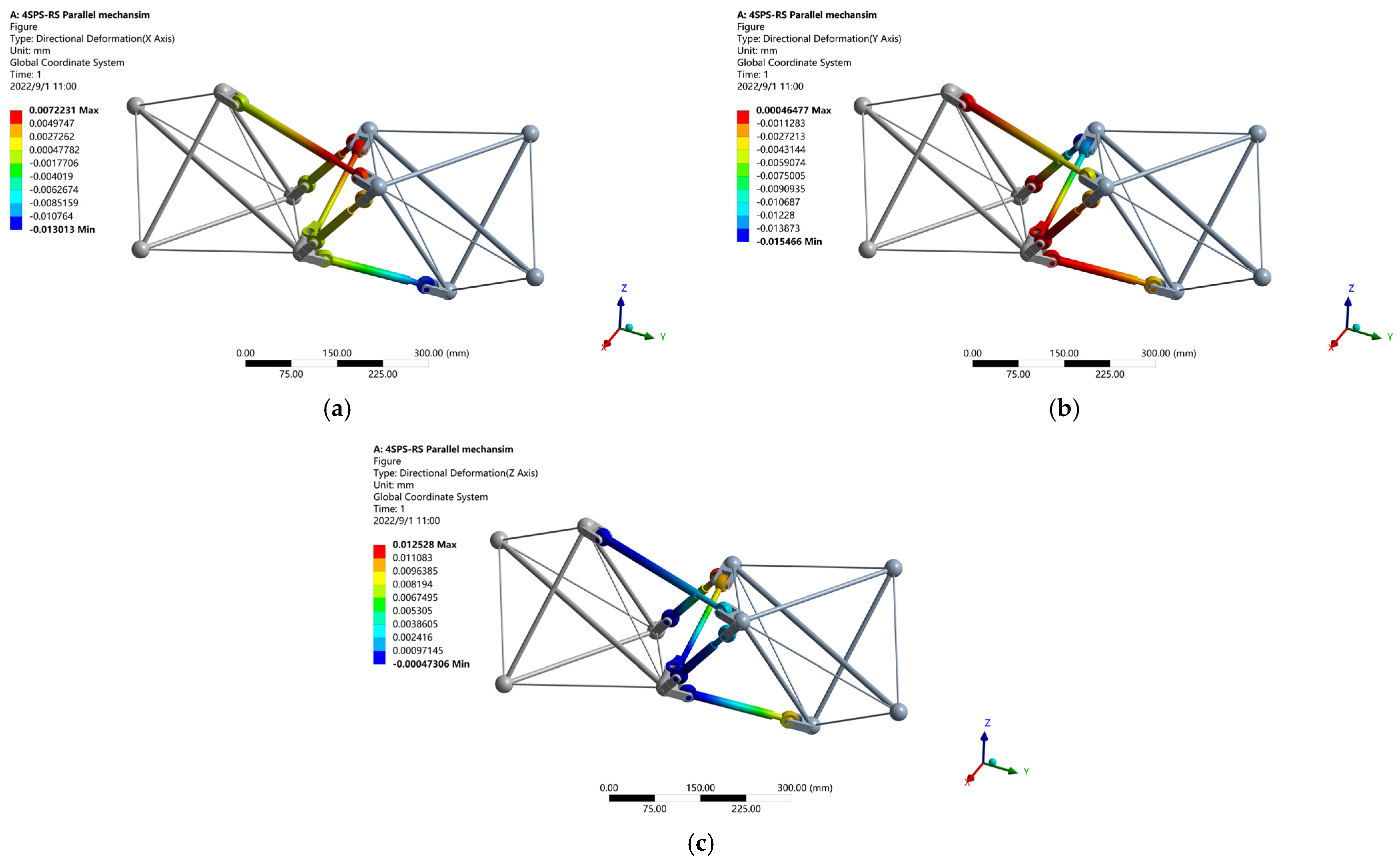
When the external load is the force of 100 N along the
z-axis and the material is structural steel, the simulation deformation is shown in
Figure 15.
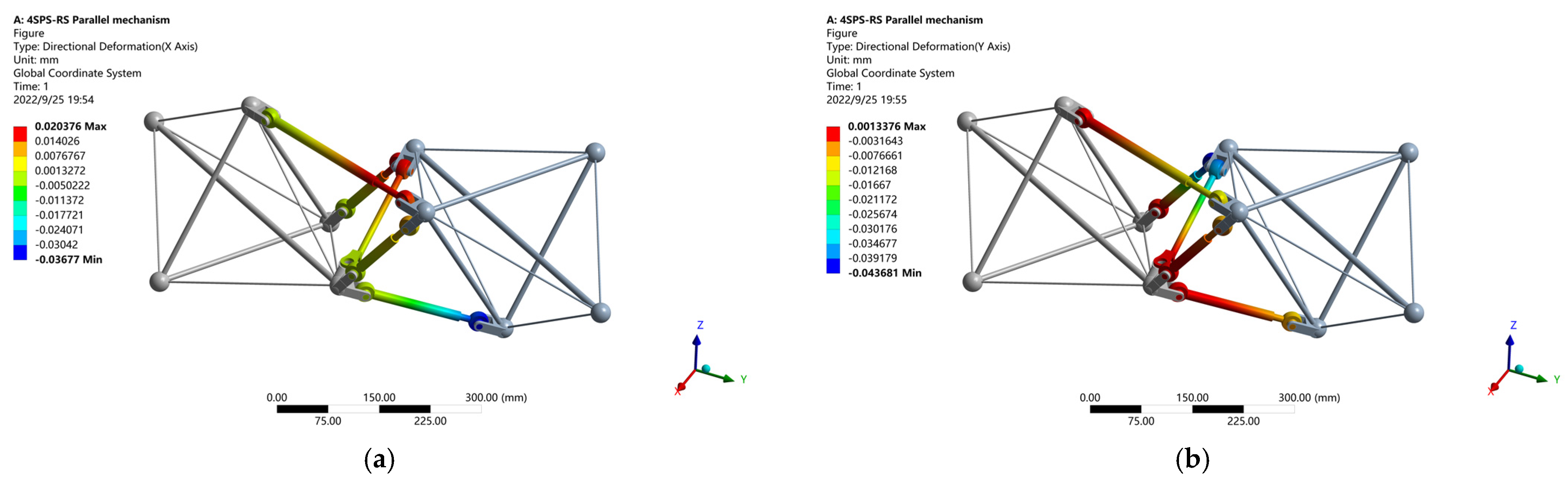
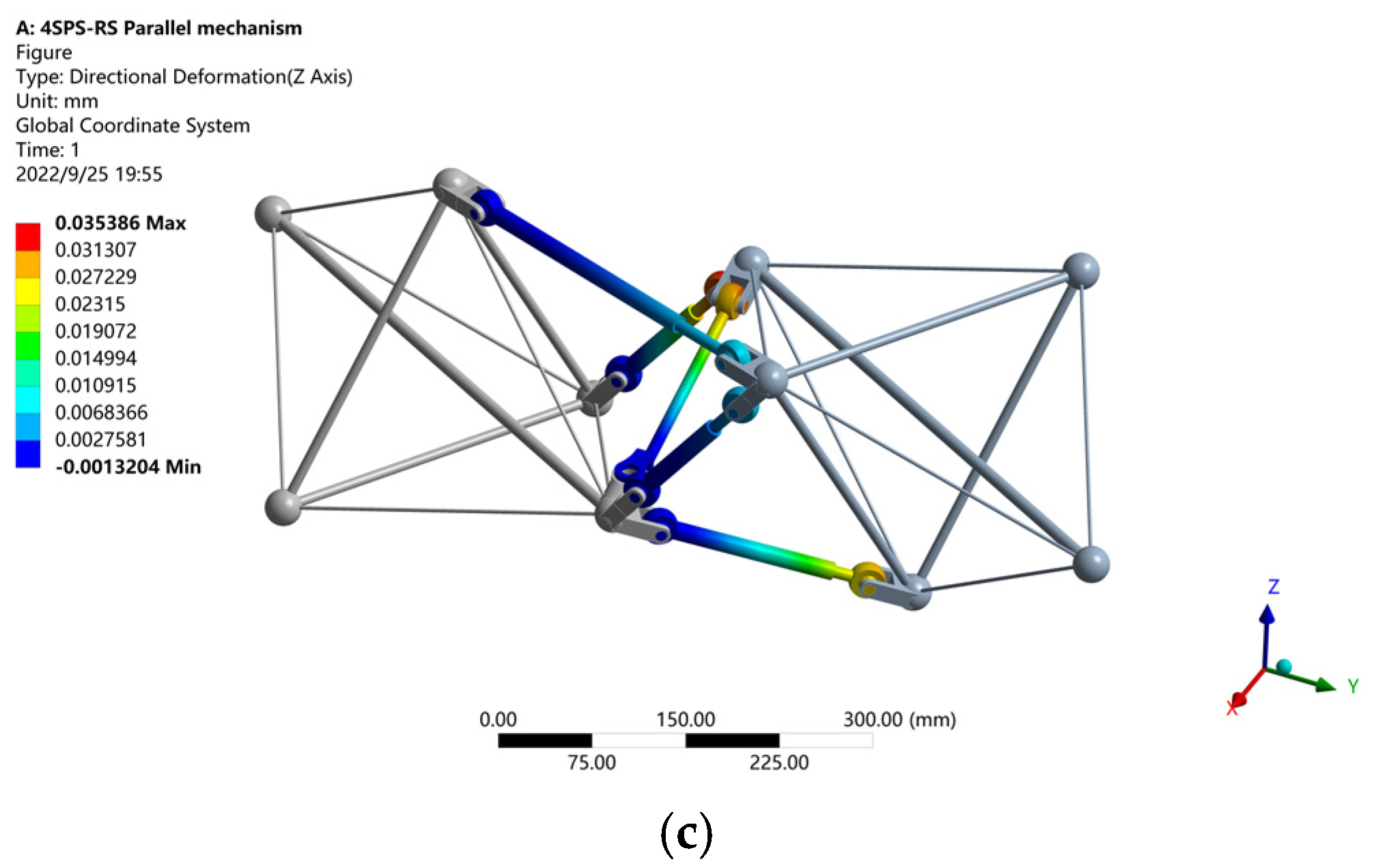
When the external load is the force of 100 N along the
z-axis and the material is 7075 aviation aluminum alloy, the simulation deformation is shown in
Figure 16.
The error between the theoretical value and the simulation value was within 8%, which verifies the correctness of the stiffness theoretical model.
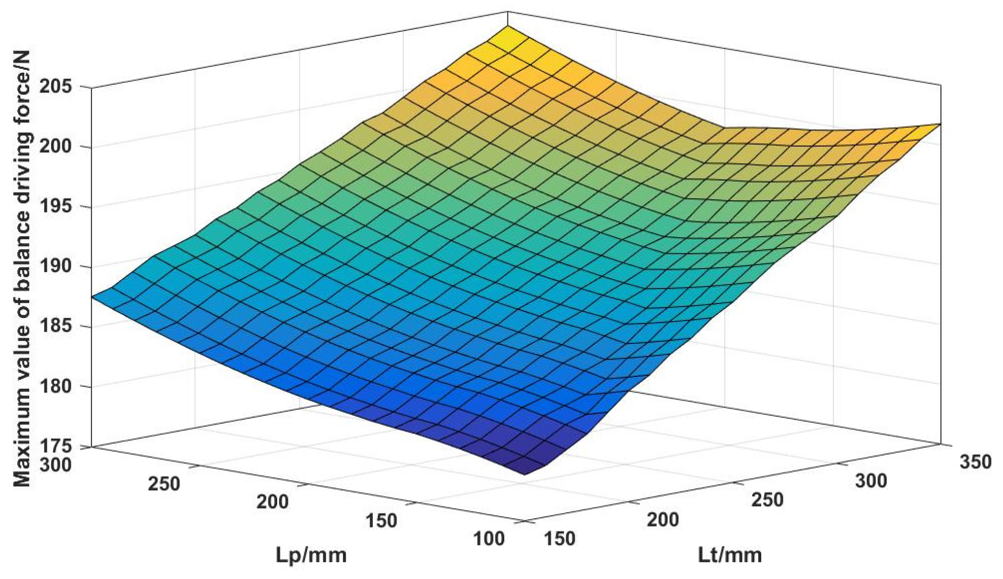
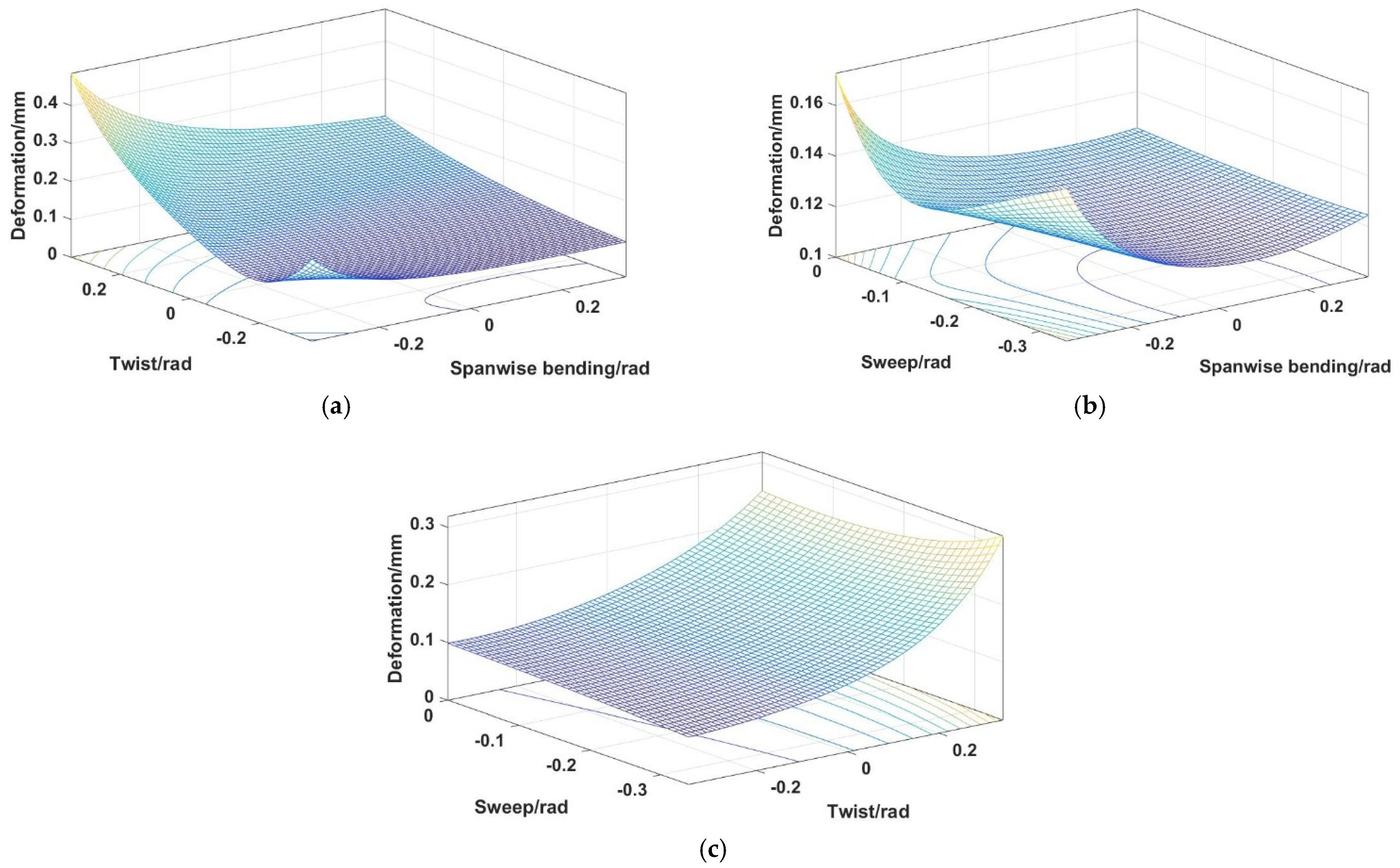
According to the mission requirements, the variation range of sweep is [−π/9~0], the variation range of twist is [−π/9~π/9], the variation range of spanwise bending is [−π/9~π/9], and the variation range of span is [0~50 mm]. The external force of 1000 N along the z-axis is applied at the origin position of the moving coordinate system. When the wing moves along the span direction to the minimum and maximum position, two parameters of the sweep, twist, and spanwise bending are changed. The total deformation along the coordinate axis of the wing morphing mechanism is obtained.
Then, any two parameters are changed at the minimum span, and the relationship between the deformation of the 4SPS-RS mechanism and the change of parameters is obtained. As shown in
Figure 17.
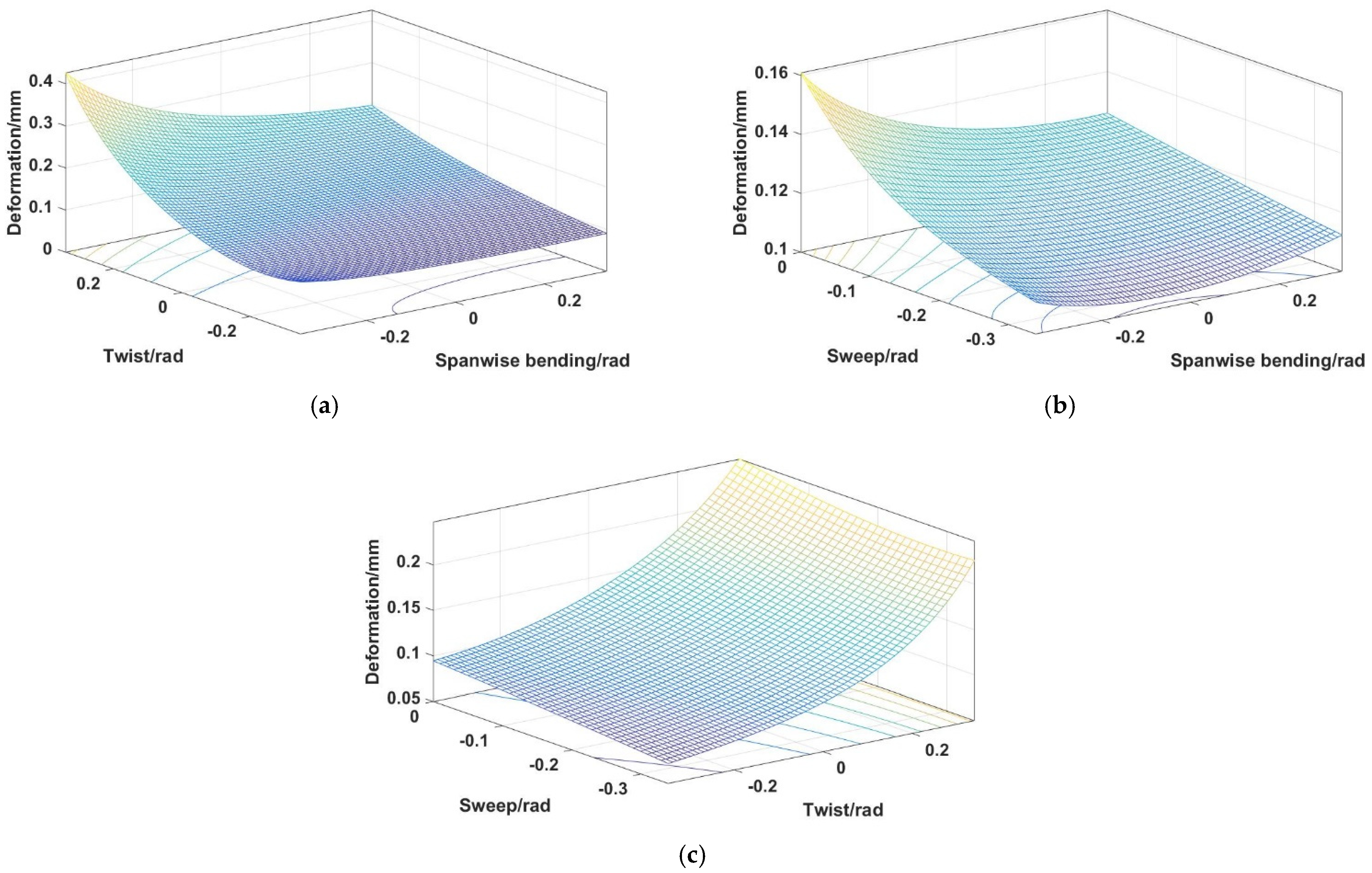
Finally, any two parameters are changed at the maximum span, and the relationship between the deformation of the 4SPS-RS mechanism and the change of parameters is obtained. As shown in
Figure 18.
By analyzing the deformation law in a large-lift environment, it was found that the wing morphing mechanism had a high degree of stiffness and bearing capacity, which could meet the morphing and bearing requirements during flight.


