Communication

Electromagnetic and Mechanical Analysis and Measurements of Interior Permanent Magnet Motors Based on Equivalent Magnetic Circuit Method

1
Department of Electrical Engineering, Chungnam National University, Daejeon 34134, Korea
2
Advanced Brake System Engineering Cell, Hyundai Mobis, Yongin-si 16891, Korea
3
Department of Smart Agriculture Systems, Chungnam National University, Daejeon 34134, Korea
4
Department of Power System Engineering, Chonnam National University, Jeonnam 59626, Korea
*
Authors to whom correspondence should be addressed.
Machines 2022, 10(10), 915; https://doi.org/10.3390/machines10100915
Submission received: 6 September 2022 / Revised: 29 September 2022 / Accepted: 5 October 2022 / Published: 9 October 2022
(This article belongs to the Topic Designs and Drive Control of Electromechanical Machines)

Abstract

:
This paper is about the magnetic field analysis of an interior permanent magnet motor (IPM motor) by using the equivalent magnetic circuit method (EMC method), which requires a small amount of computation time compared with the finite element method (FEM). IPM motors have a specific shape of rotor in which the permanent magnets are embedded. Therefore, in the bridge region, the magnetic saturation is generated due to the shape of the permanent magnet, which affects the magnetic flux density distribution in the air gap and the characteristics of the IPM motor. Thus, to design an IPM motor, the magnetic saturation effects should be considered along with the rotor shape. In addition, because the rotor of the IPM rotates at a high speed directly in connection with the load, the stress generated from the rotor must be stably distributed. Consequently, according to the rotor shape characteristics of the IPM, the stress is concentrated in the thin bridge region during high-speed rotation. When the stress generated in the bridge region exceeds the yield stress of the rotor iron core material, the bridge part is destroyed. Therefore, it is important to analyze the stress that occurs in the rotor during high-speed rotation in the rotor design stage of the IPM. In this study, we analyzed the magnetic field characteristics of an IPM motor using its equivalent magnetic circuit while considering the magnetic saturation in the bridge region. The stability of the rotor was determined by presenting a safety factor based on the maximum stress generated at the rotor for each speed. We derived the stator natural frequency to evaluate the resonance possibility between the electrical frequency and the stator natural frequency. Finally, the validity of the constructed equivalent magnetic circuit was verified by comparing the results with those obtained via the FEM analysis and experiments.

1. Introduction

Through the development of permanent magnet manufacturing technology, the use of permanent magnet electric motors having the advantages of high efficiency and high output power is increasing. These permanent magnet motors can be divided into two types depending on the shape of the rotor: surface-mounted permanent magnet (SPM) motors and interior permanent magnet (IPM) motors. Because the permanent magnet is attached to the surface of the rotor in SPM motors, it is necessary to fabricate a non-magnetic-material tube for preventing the magnet from scattering during high-speed operation. On the other hand, IPM motors could prevent the scattering of permanent magnets during high-speed operation because the permanent magnet is embedded in the rotor. However, placing the permanent magnet in the rotor causes it to have a magnetic polarity due to the differences in reluctance. Therefore, IPM motors could make better use of the magnetic and reluctance torques during operation time, and, through field weakening control strategies, make use of their wide output range and their advantages at high-speed operation [1,2]. The analysis methods for permanent magnet motors can be divided into the analytical method, the finite element method (FEM), and the equivalent magnetic circuit (EMC) method. The analytical method consists in analyzing the magnetic field characteristics of the motor by solving its differential equations using Maxwell’s equations [3,4,5,6]. It is able to derive high accuracy and relatively quick analysis results compared with FEM. In order to analyze the magnetic field, we should solve the equation derived by Maxwell equation, which has a high level of difficulty. In the case of FEM, it is easy to analyze through commercial tools. However, in order to obtain the accuracy of analytical results, it is necessary to have a large number of element divisions, which leads to a long analysis time. Therefore, for having reliable results, the FEM analysis model needs to appropriate the number of elements depending on the experience of the analyzer. The EMC method does not consist in performing analyses through complex mathematical equations but can be equally used to analyze the magnetic circuit without taking into consideration the shape of the machine while considering the magnetic saturation of the magnetic circuit [7]. In addition, if the saturation of the rotor bridge region is not considered, the magnitude of the back-EMF derived through the air-gap magnetic flux density becomes inaccurate. This leads to difficulty in deriving detailed dimensions of the rotor and stator during the initial design of the IPM. Therefore, considering the proposed saturation region, the EMC method in this paper contributes to the fast characteristic analysis and the initial design of the bar-type IPM.
Furthermore, the IPM should identify the mechanical characteristics owing to the rotor structure in which the permanent magnet is embedded in the rotor iron core. Therefore, although the electromagnetic characteristics are excellent, if the maximum stress exceeds the yield stress of the rotor core, the core may be damaged during high-speed operation. The mechanical stability was evaluated by comparing the stress distribution and magnitude of the maximum stress generated by the rated speed. In addition, when the resonant frequency of the stator and rotor is close to the electromagnetic excitation frequency, the vibration increases further. For this reason, it is necessary to analyze the structural characteristics of the motor, namely the natural frequency and the mode shape. Therefore, this paper performed the magnetic field characteristics of an IPM motor, which were analyzed using the EMC method, and the rotor stability was determined by analyzing the stress generated by the rotor when rotating at the rated speed. Furthermore, by deriving the stator mode frequency, we evaluated the resonance. Finally, its feasibility was verified by comparison with the results of the FEM analysis.

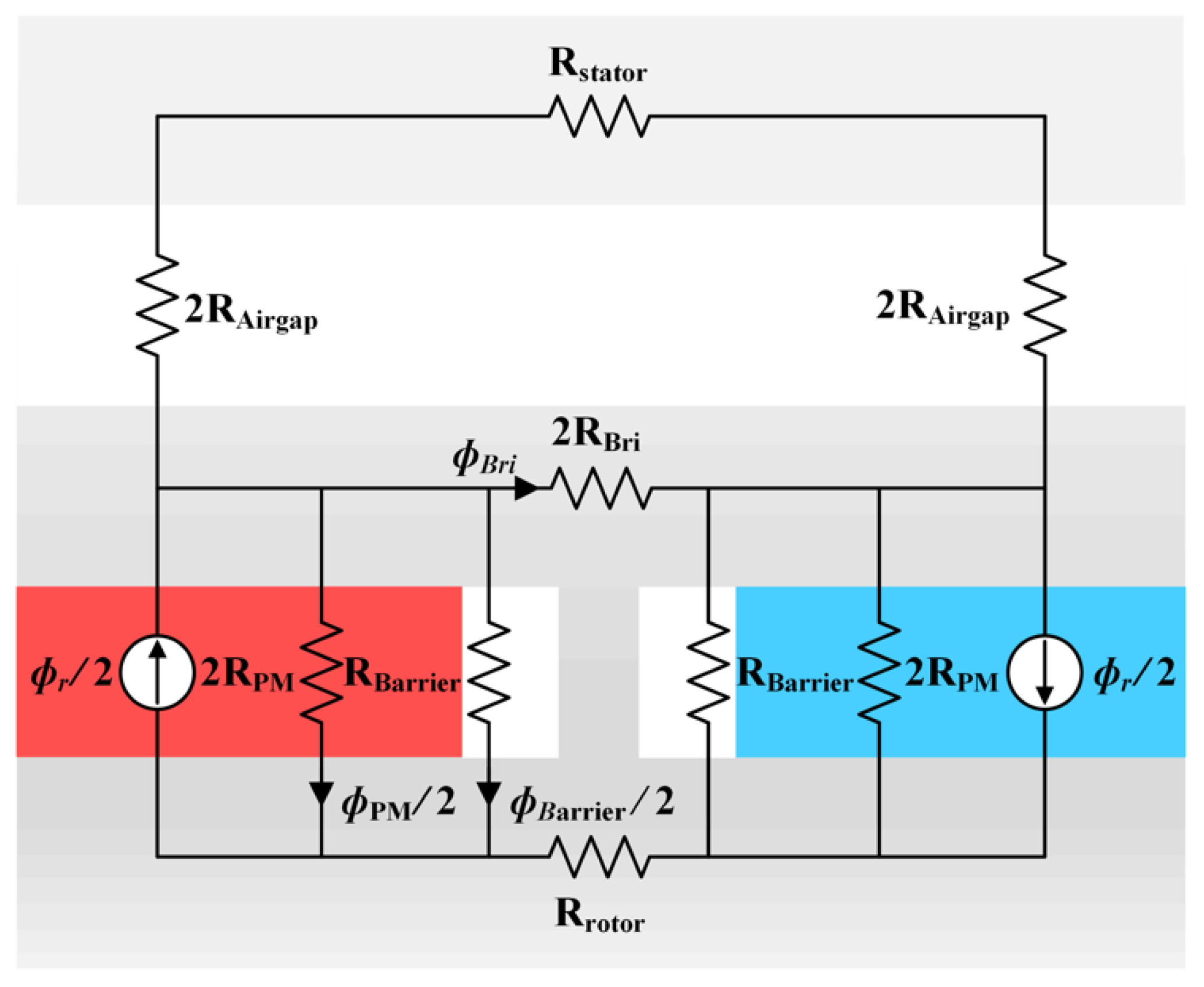
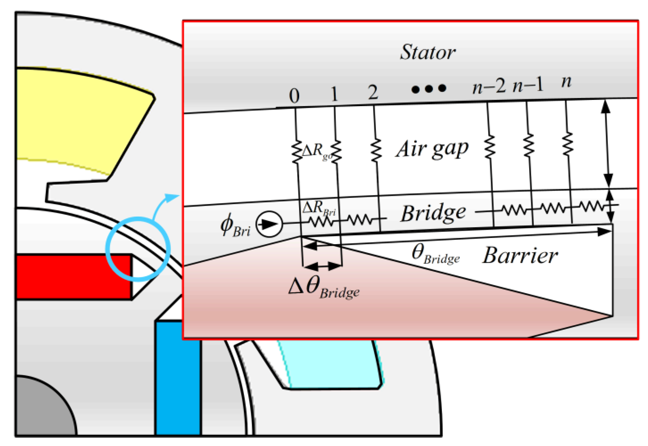
2. Mechanical and Magnetic Characteristics Analysis Using the Equivalent Magnetic Circuit Method Considering the Magnetic Saturation of Bridge Region

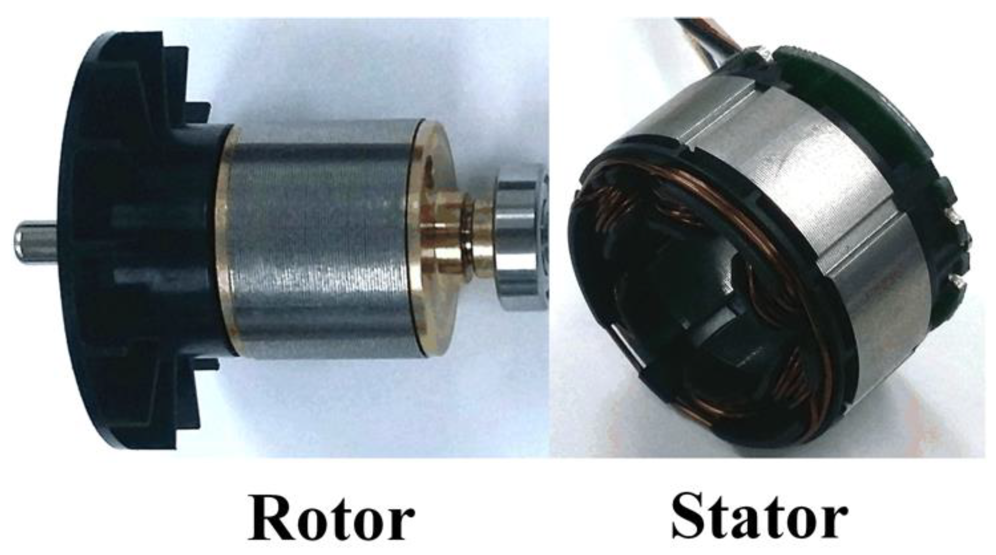
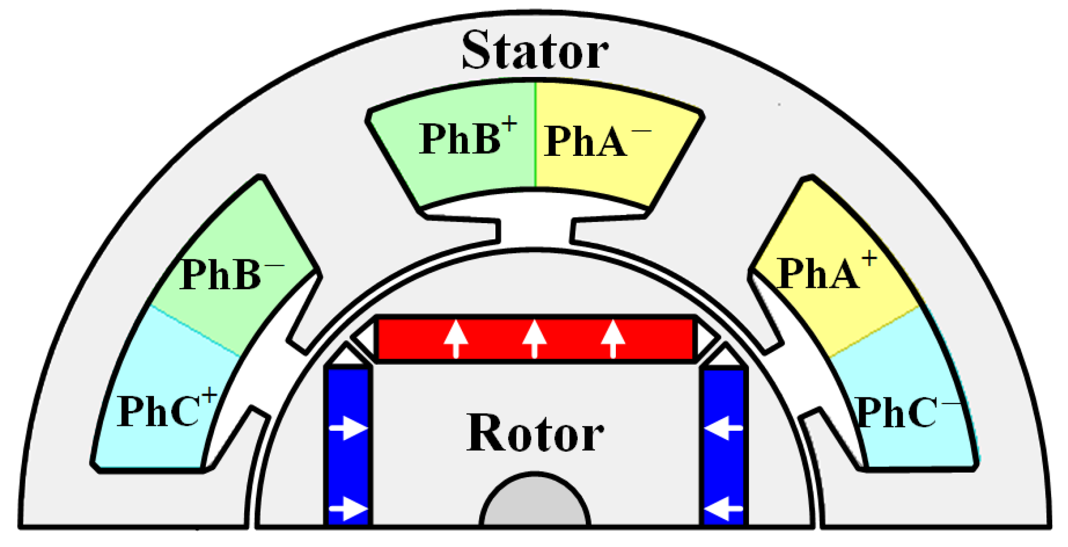
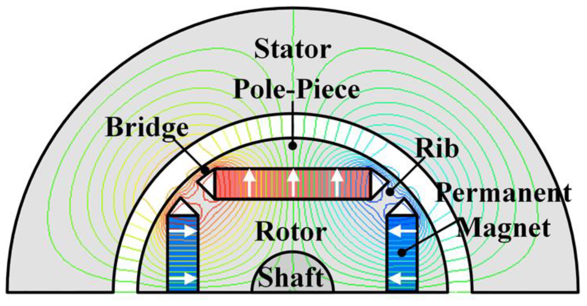
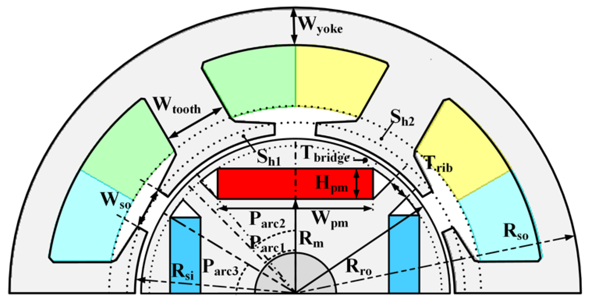
2.1. The Analysis Model and Assumptions

The actual model and the analysis model used for our EMC analysis are shown in Figure 1 and Figure 2, respectively.
They consisted of an IPM motor with a combination of four poles and six slots with concentrated winding. For our analysis, some simplifying assumptions were required for using the EMC method. First, the magnetic permeability of the iron core was assumed to be infinite. Secondly, the magnetic saturation was ignored, except for the magnetic saturation at the rib and bridge regions. Thirdly, the demagnetization of the permanent magnet was not considered. Fourthly, the end effect in the axial direction was not considered. Fifthly, the slot effect was ignored. The rotor geometry of the analysis model used consisted of a barrier, a bridge, a pole piece, a rib, and a permanent magnet, while having the shape of a typical IPM motor. The analysis model used for the EMC method after applying the simplifying assumptions and its equivalent magnetic circuit according to the rotor components are shown in Figure 3 and Figure 4, respectively. Each of the resistors represents the reluctance of a component of the motor according to our assumptions.

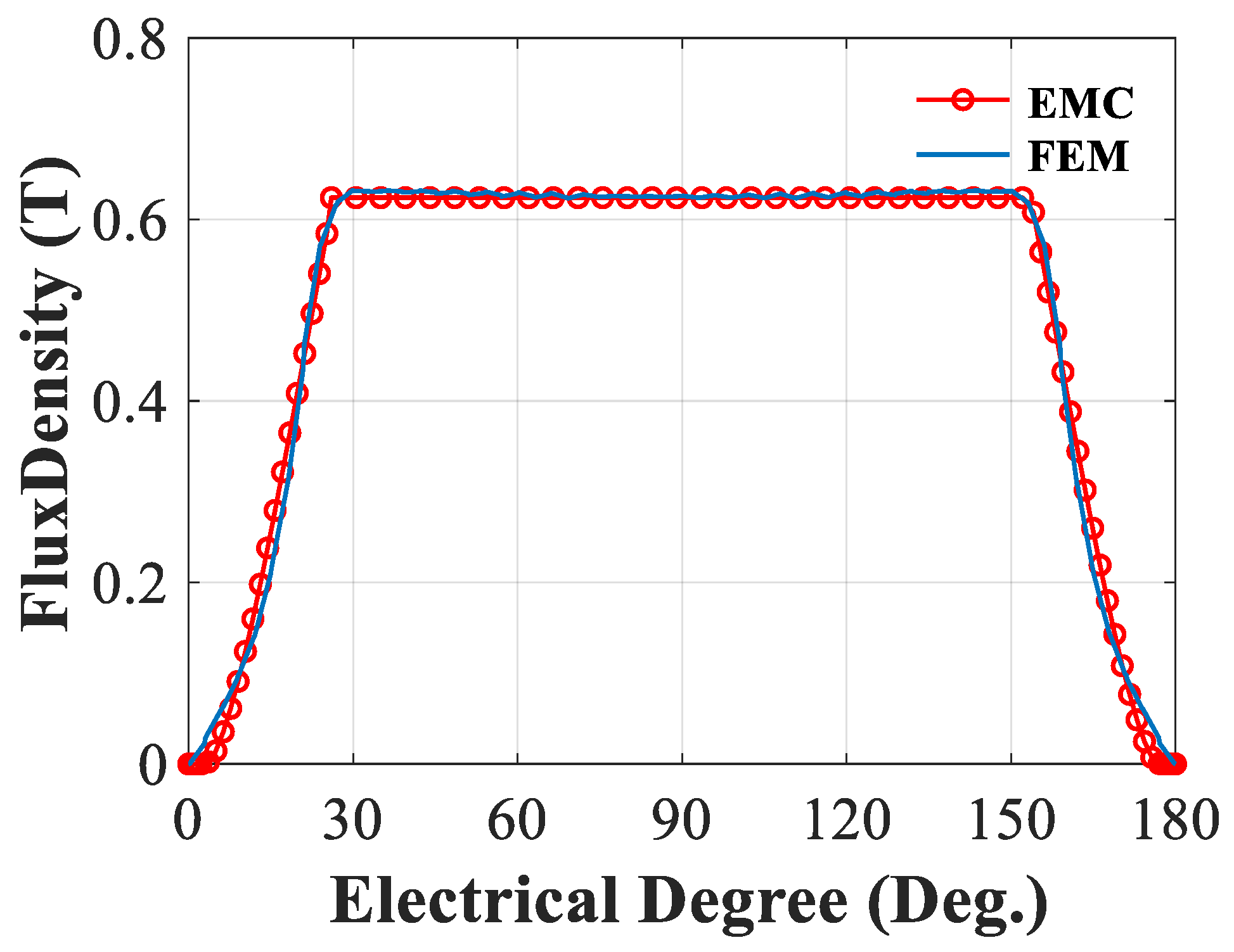
2.2. The Magnetic Characteristic Analysis

To analyze the magnetic field characteristics using the EMC method, a circuit analysis has to be performed. In this case, because the reluctances and magnetic fluxes are represented by resistances and currents in the equivalent electrical circuit, respectively, their definition should be explained. Figure 5 shows the concept of reluctance in the bridge region. If the angle of the bridge region from the end of the barrier to the pole piece region increases, the magnetic saturation becomes more intense as it approaches the permanent magnet, so that the magnitude of the reluctance of the bridge region increases from the end of the barrier to the permanent magnet. In order to consider the magnetic saturation of the bridge region, the reluctance of the bridge region consisted of the reluctance units, as shown Figure 5. These units of reluctance on the bridge region can be expressed as follows in Equations (1)–(6).
For calculating the reluctance units of the bridge region, the nonlinear magnetic permeability should be considered, which can be derived via curve-fitting methods. There are parameters that need to be defined before deriving the reluctances and magnetic fluxes using the equations.
Table 1 and Figure 6 show the parameter values required to derive the rotor’s reluctance and magnetic flux. An appropriate thickness of the bridge should be chosen so as to prevent breakage due to inertia during high-speed operation. The thickness of the bridge depends on the size of the device, but is usually chosen to be within 0.6 mm. Therefore, the formula for the magnetic flux of the equivalent magnetic circuit can be summarized as shown in Equations (1)–(3).
ϕ r = B r A P M = B r W P M L s t k
ϕ B r i = B s a t A B r i = B s a t T B r i L s t k
ϕ A i r g a p 2 = ϕ r 2 ( ϕ P M 2 + ϕ B a r r i e r 2 + ϕ R i b )
Here, APM is the area of the permanent magnet, ABri is the area of the bridge, and Bsat is the saturation flux density at the bridge. The reluctance of each region can be expanded as shown in Equations (4)–(6).
R A i r g a p = g 0 μ 0 A A i r g a p
R P M = H P M μ 0 μ r A P M = H P M μ 0 μ r W P M L s t k
R B a r r i e r = H B a r r i e r _ A v g μ 0 W B a r r i e r _ A v g L s t k
Here, RAirgap is the reluctance of the air gap, RPM is the reluctance of the permanent magnet, RBarrier is the reluctance of the barrier, HBarrier_Avg is the height of the barrier, and WBarrier_Avg is the width of the barrier. In order to derive the magnetic flux density distribution in the air gap, the area at the center of the gap should be calculated as follows. In our case, we considered the reluctances of the air gap having the same angle. Thus, the reluctance of the bridge region can be expressed by Equations (7)–(9) [8,9,10].
A A i r g a p = α p 2 π ( R s i g 0 / 2 ) 2 p L s t k
Δ R g o = g 0 μ 0 ( R s o Δ θ B r i d g e π / 180 ) L s t k
Δ R B r i = ( R r o Δ θ B r i d g e π / 180 ) μ 0 μ r T B r i d g e L s t k
λ a = k w N p h ϕ a i r g a p cos ( θ e )
e a = d λ a d t
Through the results of the magnetic flux density distribution at the air gap, the magnetic flux of one phase winding can be expressed in the form of its fundamental wave. The magnitude of the back-EMF can be derived through the linkage flux of one phase winding. For this purpose, the basic waveform of the back-EMF can be derived from Equations (10) and (11). Here kω is the winding coefficient and θe is the electrical angular degree. Figure 7 shows the comparison results between the waveform of the back-EMF derived through the finite element analysis and the back-EMF derived through the proposed EMC method.
Through Figure 7, it was confirmed that the air-gap flux density of the EMC method considering the saturation of the bridge region presented in this paper coincides with the air-gap flux density derived from the finite element analysis.

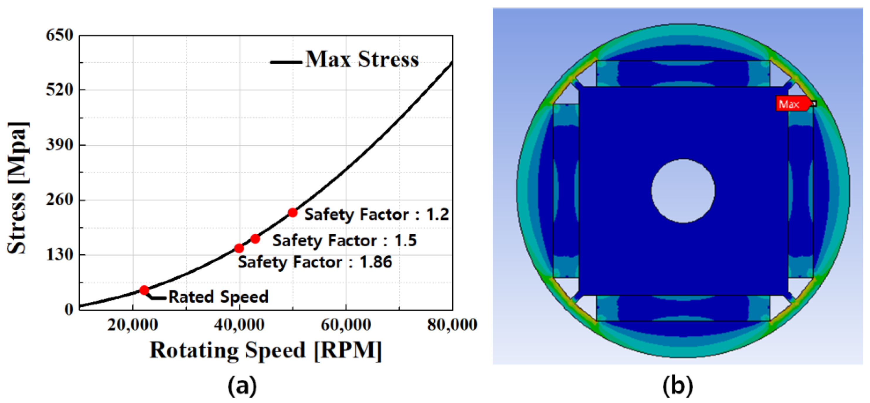
2.3. Rotor Stress Analysis

In the IPM, the design of a bridge to secure the stability of the rotor against high-speed rotation is important, and the width is determined by the stress-limiting condition of the rotor core. Considering only the electromagnetic characteristics, it is recommended to narrow the width of the bridge in each barrier layer to minimize the leakage of the magnetic flux remaining in the rotor as well as maximize the saliency ratio [11,12]. However, if the width of the bridge is designed to be narrow, and the driving speed of the device increases according to the requirements, the bridge of the rotor may be damaged by the centrifugal force generated by the rotation of the motor. Therefore, a wider width and better consideration of the mechanical strength can prevent damage to the rotor [10]. In the motor designer’s aspect, it is essential in the design stage to select the appropriate bridge width through electromagnetic and structural analysis of the rotor, as well as to determine whether the rotor core is damaged at operating speed through stress distribution. In this study, the stability was identified based on the safety factor derived from the maximum stress generated from the rotor, and the safety rate was derived using Equation (12). Table 2 show the mechanical property of core and permanent magnet of rotor.
S a f e t y _ F a c t o r = T e n s i l e   Y i e l d   S t r e n g t h   [ MPa ] M a x i m u m   S t r e s s   [ MPa ] 1.5
The safety factor, which was determined to be appropriate to operate within the operating speed of the motor, was selected as 1.5. Moreover, as illustrated in Figure 8, it was derived through rotor structure analysis with a safety rate of approximately 43,000 rpm. Therefore, in the case of the IPM motor in this study, it was considered that there was no damage to the rotor core at the rated speed.

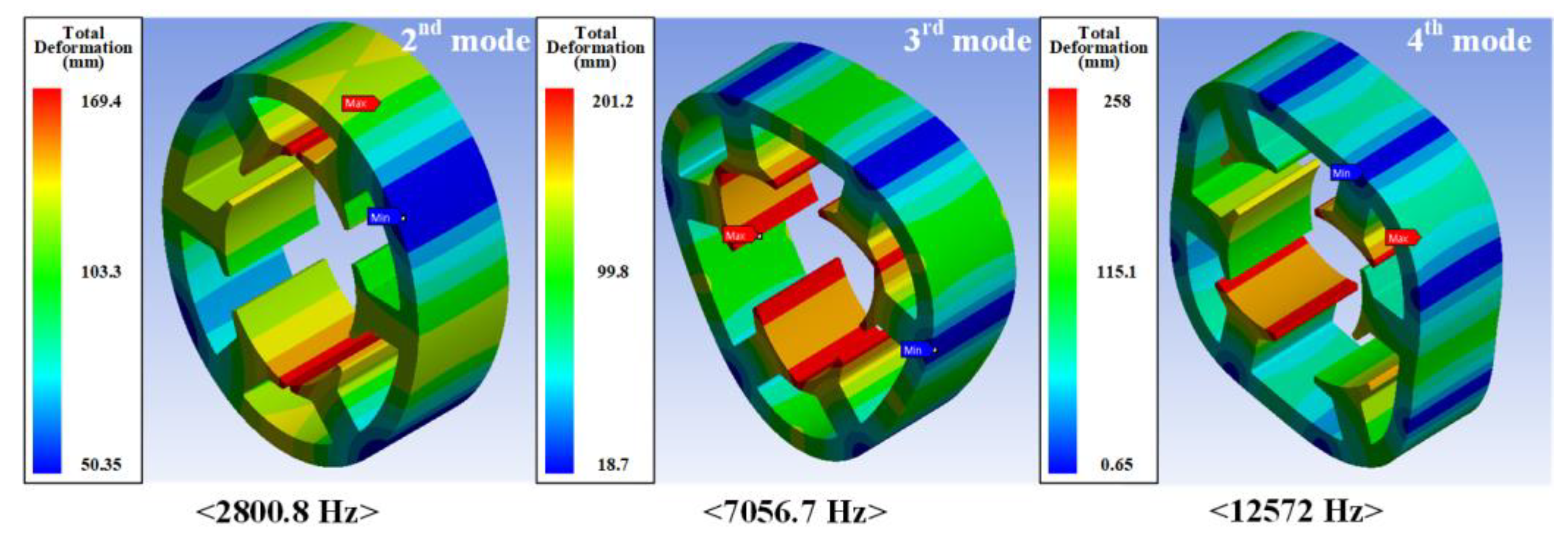
2.4. Stator Modal Analysis

As a method for predicting the natural frequency of the stator, the natural frequency and mode shape were predicted by viewing the stator as a simple ring and considering the stator teeth and coil as additional mass. In addition, the stator teeth were considered as cantilever beams connected to the stator and an analysis model was selected. The stator of the motor is a major component of the motor and directly receives the electromagnetic excitation force and has the greatest structural influence on the vibration and noise generation of the motor, such as the resonance frequency being within the frequency range of interest. Figure 9 shows the mode analysis results of the stator core designed using the finite element analysis. The natural frequencies in the 2nd, 3rd and 4th modes are 2800.8 Hz, 7056.7 Hz, and 1120.3 Hz, respectively. From the analysis result, it can be considered that there is no effect due to resonance because there is no corresponding operating range for the electric frequency of the motor and the natural frequency of the stator.

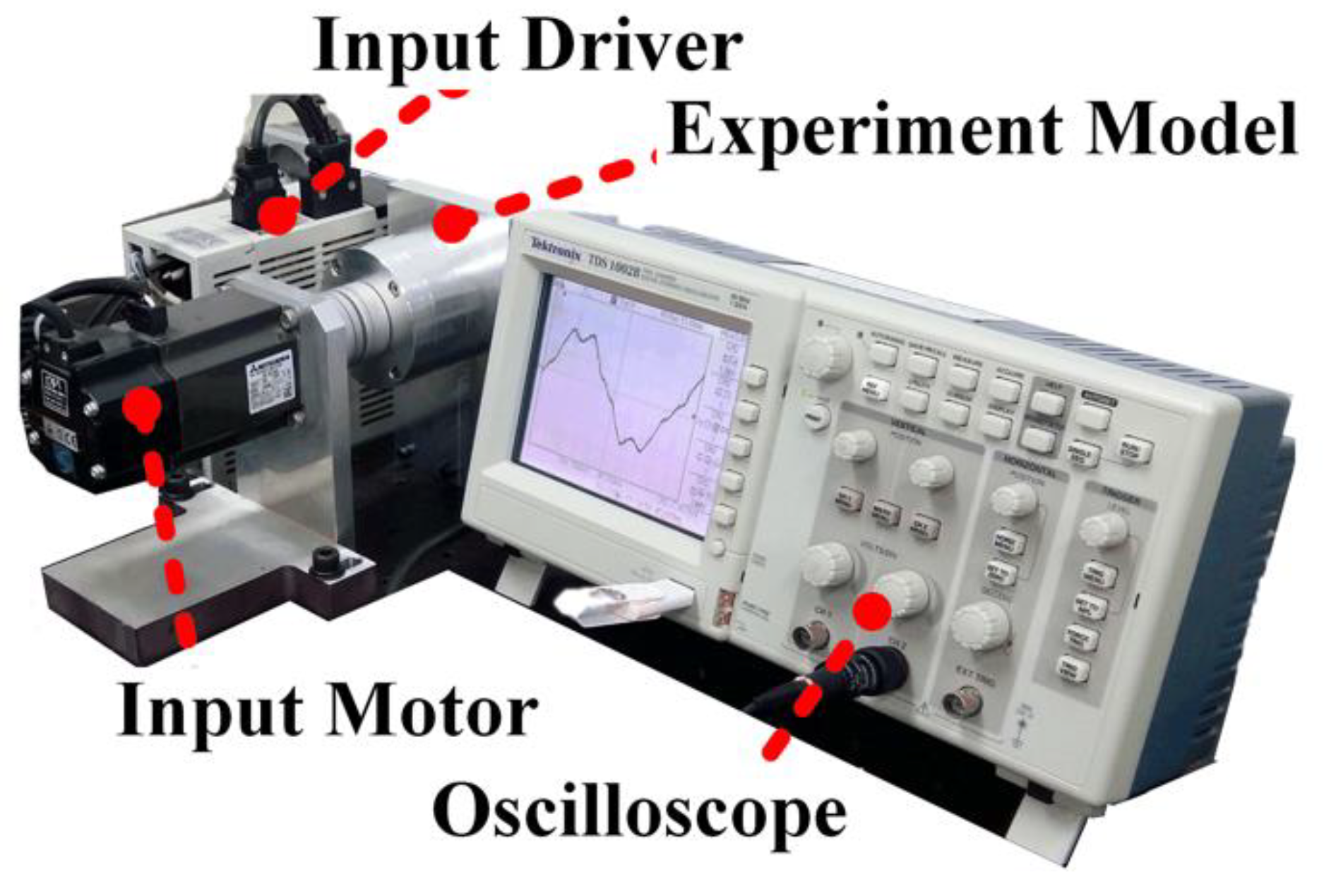
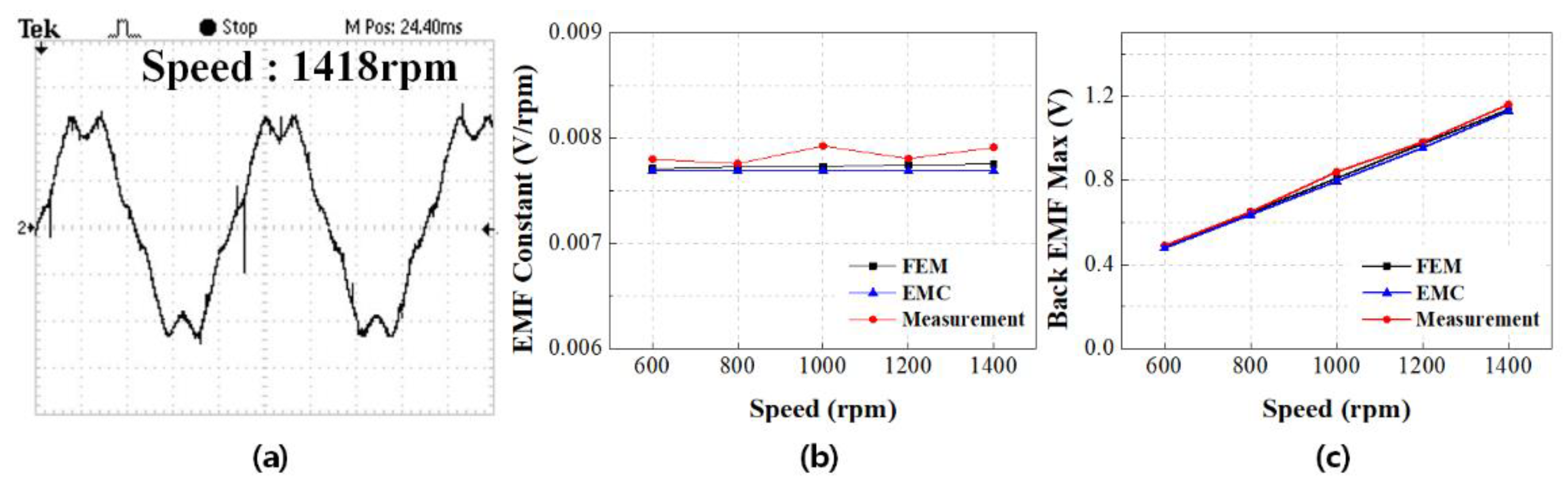
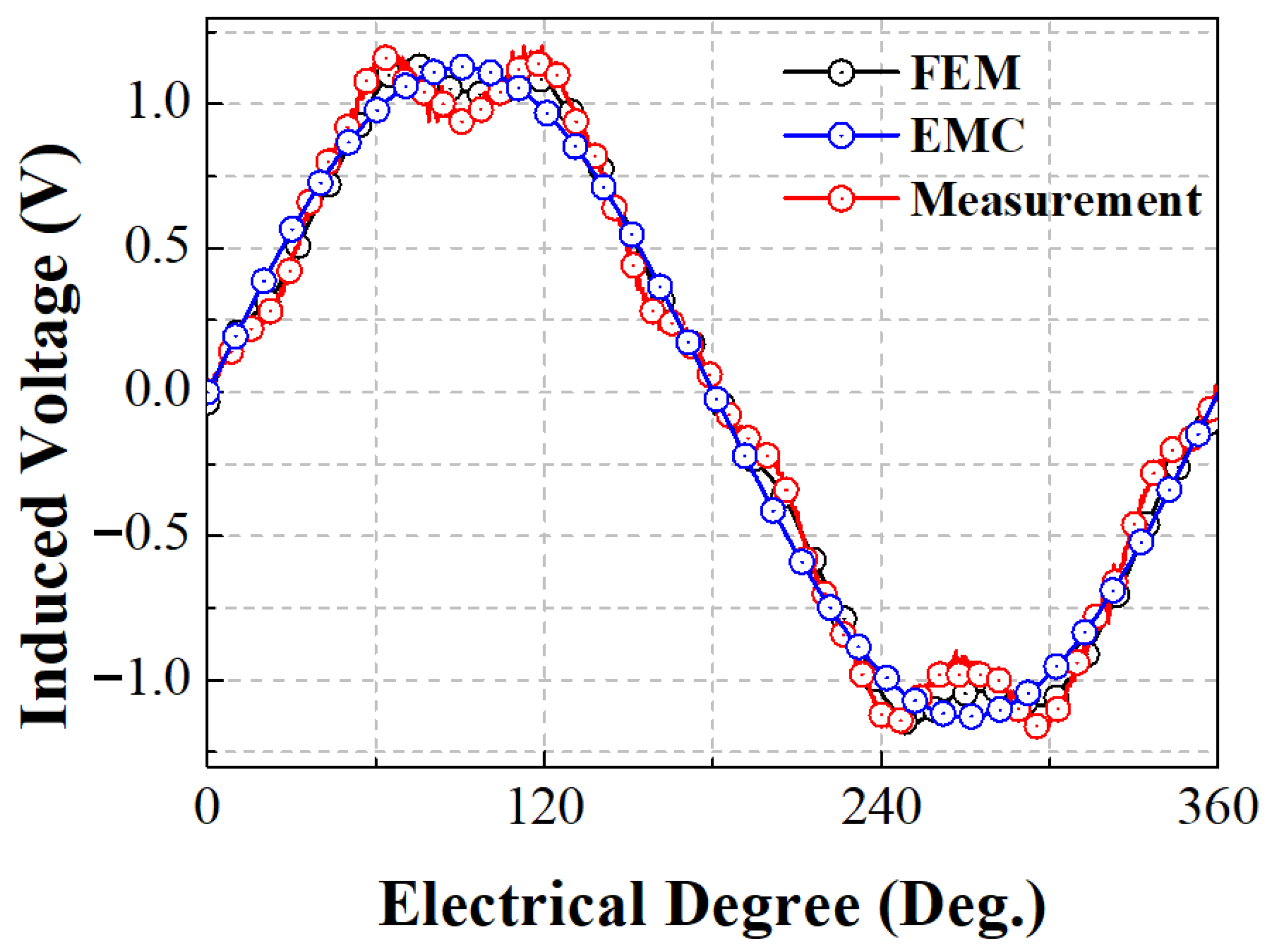
3. Experimental Validation

Experimental Validation of Analysis Results

A model with the design initially presented was constructed to compare the results of our analysis of the model initially designed (obtained via the equivalent magnetic circuit method presented in this paper) with the measured results and to verify the validity of the design method.
An experimental model was made for the verification of our analysis results. 35PN440 was used as the iron core material for the rotor and stator, and the permanent magnet used was made of N35SH material. Figure 10 shows the measurement system for the no-load back-EMF experiment. No-load back-EMF is the voltage of the motor that occurs when the rotor of each phase of the motor is open and the rotor is rotated at an arbitrary speed through the input driver. In this study, no-load back-EMF experiments were performed at 200 rpm steps from 600 rpm to 1400 rpm.
The measured values were compared with our analytical results using the equivalent magnetic circuit method and the FEM. Figure 11 shows the results of a no-load back-EMF measurement, showing a varying back-EMF and back-EMF constants according to the motor speed. It can be seen that the results of the FEM analysis and the measured waveforms are in good agreement due to the effects of the stator slot shape and the magnetic saturation phenomenon.
Because of the influence of harmonics in the experiment, the results of the measurements, those of the equivalent magnetic circuit, and those obtained via the FEM analysis show differences, but these are lower than 5%.
Therefore, it can be seen that the errors of the FEM analysis and the error in the values obtained via the equivalent magnetic circuit did not exceed 5%. Figure 12 shows a graph comparing the changes in the back-EMF values. The errors of the back-EMF values obtained with the proposed method can be seen by comparing them with the analytical and measurement results of the back-EMF experiments.

4. Conclusions

This paper is about a magnetic characteristics analysis using the equivalent magnetic circuit method while considering the magnetic saturation. The analysis was performed considering the saturation in the bridge region. The validities of the equivalent magnetic circuit model and the proposed analytical method considering the saturation of the bridge region were verified by comparing their results with the FEM results. The experimental results of the back-EMF measurement of the proposed analytical model were compared with the results of the FEM analysis using the equivalent magnetic circuit method. We confirmed that the error between the analytical results obtained via the equivalent magnetic circuit method and the results of the FEM analysis is within 5%. In addition, the safety factor was derived based on the maximum stress generated in the rotor according to each speed through analysis of the rotor structure, and the mechanical stability at the rated speed was identified through the safety factor. Based on the results, it is possible to design a rotor structure using the EMC method proposed in this study, and the IPM mechanical stability can be determined through structural analysis. Finally, the resonance between the electrical frequency and the natural frequency of the stator was determined through the stator modal analysis, and the effect on the vibration and noise caused by the resonance was analyzed. This process and methodology can contribute to the design of IPM rotors.

Author Contributions

K.-H.S.: conceptualization, review and editing; J.-Y.C.: conceptualization, review and editing; Y.-K.L.: analysis, original draft preparation; T.-K.B.: experiment, motor control algorithm and co-simulation; S.-T.J.: experiment and motor control algorithm; Y.-J.K.: experiment and motor control algorithm. All authors have read and agreed to the published version of the manuscript.

Funding

This work was supported by the Korea Institute of Planning and Evaluation for Technology in Food, Agriculture, Forestry (IPET) through the Eco-friendly Power Source Application Agricultural Machinery Technology Development Program, funded by the Ministry of Agriculture, Food and Rural Affairs (MAFRA) (322047-5). This work was supported by the National Research Foundation of Korea (NRF) grant funded by the Korea government (MSIT). (No.2020R1A2C1007353).

Institutional Review Board Statement

Not applicable.

Informed Consent Statement

Not applicable.

Data Availability Statement

The data presented in this study are available on request from the corresponding author.

Conflicts of Interest

The authors declare no conflict of interest.

References

  1. Gerada, D.; Mebarki, A.; Brown, N.L.; Gerada, C.; Cavagnino, A.; Boglietti, A. High-Speed Electrical Machines Technologies, Trends, and Developments. IEEE Trans. Ind. Electr. 2014, 61, 2946–2959. [Google Scholar] [CrossRef]
  2. Kim, H.K.; Hur, J. Dynamic Characteristic Analysis of Irreversible Demagnetization in SPM- and IPM-Type BLDC Motors. IEEE Trans. Ind. Appl. 2012, 53, 982–990. [Google Scholar] [CrossRef]
  3. Lee, T.Y.; Seo, M.K.; Kim, Y.J.; Jung, S.Y. Motor Design and Characteristics Comparison of Outer-Rotor-Type BLDC Motor and BLAC Motor Based on Numerical Analysis. IEEE Trans. Ind. Appl. 2016, 26, 5205506. [Google Scholar] [CrossRef]
  4. Yu, J.S. Optimal Design of Interior Permanent Magnet Synchronous Motor considering Magnetic Saturation and Flux Weakening Control Capability. Master’s Thesis, Chungnam National University, Daejeon, Korea, 2014. [Google Scholar]
  5. Lubin, T.; Mezani, S.; Rezzoug, A. Exact Analytical Method for Magnetic Field Computation in the Air Gap of Cylindrical Electrical Machines Considering Slotting Effects. IEEE Tran. Magn. 2010, 46, 1092–1099. [Google Scholar] [CrossRef] [Green Version]
  6. Zhu, Z.Q.; Howe, D.; Chan, C.C. Improved Analytical Model for Predicting the Magnetic Field Distribution in Brushless Permanent-Magnet Machines. IEEE Trans. on Magn. 2002, 38, 229–238. [Google Scholar] [CrossRef] [Green Version]
  7. Bianchi, N.; Bolognani, S.; Luise, F. Analysis and design of a PM Brushless Motor for high-speed operations. IEEE Trans. Energy Convers. 2014, 20, 629–637. [Google Scholar] [CrossRef]
  8. Kim, W.H.; Kim, K.C.; Kim, S.J.; Kang, D.W.; Go, S.C.; Lee, H.W.; Chun, Y.D.; Lee, J. A Study on the Optimal Rotor Design of LSPM Considering the Starting Torque and Efficiency. IEEE Tran. Magn. 2005, 45, 1808–1811. [Google Scholar] [CrossRef]
  9. Kim, K.C.; Koo, D.H.; Hong, J.P.; Lee, J. A Study on the Characteristics Due to Pole-Arc to Pole-Pitch Ratio and Saliency to Improve Torque Performance of IPMSM. IEEE Tran. Magn. 2007, 43, 2516–2518. [Google Scholar] [CrossRef]
  10. Lee, J.-J.; Lee, J.; Kim, K.-S. Design of a WFSM for Electric Vehicle Based on a Nonlinear Magnetic Equivalent Circuit. IEEE Trans. Appl. Supercon. 2018, 28, 5206304. [Google Scholar] [CrossRef]
  11. Shin, K.H.; Choi, J.Y.; Cho, H.W. Characteristic Analysis of Interior Permanent-Magnet Synchronous Machine with Fractional-Slot Concentrated Winding Considering Nonlinear Magnetic Saturation. IEEE Trans. Appl. Supercond. 2016, 26, 5200404. [Google Scholar] [CrossRef]
  12. Cao, H.; Wang, S.; Huang, S. Performance Analysis of IPMSM Based on Stress Calculation of Iron Core. In Proceedings of the 2017 IEEE Transportation Electrification Conference and Expo, Asia-Pacific, Harbin, China, 7–10 August 2017. [Google Scholar]
Figure 1. The actual model used for the equivalent magnetic circuit analysis.
Machines 10 00915 g001
Figure 2. The shape of analysis model.
Machines 10 00915 g002
Figure 3. The shape of analysis model with assumptions.
Machines 10 00915 g003
Figure 4. The magnetic circuit constructed for Equivalent Magnetic Circuit Method.
Machines 10 00915 g004
Figure 5. The concept of the reluctance to consider the magnetic saturation of the bridge region of IPM rotor.
Machines 10 00915 g005
Figure 6. The parameter of the equivalent magnetic circuit method for the magnetic saturation of the bridge region.
Machines 10 00915 g006
Figure 7. The magnetic flux density distribution of the equivalent magnetic circuit method considering the magnetic saturation of the bridge region.
Machines 10 00915 g007
Figure 8. Stress analysis result according to rotating speed and distribution. (a) Max stress plot. (b) Stress distribution at the rotor core.
Machines 10 00915 g008
Figure 9. Stator modal analysis results: 2nd mode, 3rd mode, 4th mode.
Machines 10 00915 g009
Figure 10. The experiment system for validation of the equivalent magnetic circuit method through measuring the back-EMF.
Machines 10 00915 g010
Figure 11. The results of the back-EMF measurement. (a) experiment result, (b) back-EMF constant, and (c) back-EMF max value result.
Machines 10 00915 g011
Figure 12. The results of the back-EMF measurement.
Machines 10 00915 g012
Table 1. Parameters for the equivalent magnetic circuit method for considering the magnetic saturation in the bridge region.
ParameterValueUnit
Pole number: 2 p 4-
Height of PM: H P M 2mm
Length of Air gap: g A i r g a p 0.5mm
Thickness of Bridge: T B r i 0.8mm
Length of Stack: L s t k 15mm
Outer Radius of Stator: R s o 48mm
Pole-Arc: P a r c 1 45deg
Magnet-Arc: P a r c 3 33.75deg
Bridge-Arc: θ B r i d g e , ( P a r c 2 P a r c 3 ) 6.21deg
Table 2. Rotor core and magnet material properties.
ItemsValueUnit
35PN440N35SH
Density77007600Kg/m3
Young’s modulus195160GPa
Poisson’s ratio0.250.24-
Tensile Yield strength27380MPa
Publisher’s Note: MDPI stays neutral with regard to jurisdictional claims in published maps and institutional affiliations.

