Article

The Effect of Inflow Distortion on the Rotordynamic Characteristics of a 1400-MW Reactor Coolant Pump Annular Seal

1
School of Energy and Power Engineering, Dalian University of Technology, Dalian 116024, China
2
School of Naval Architecture and Ocean Engineering, Dalian Maritime University, Dalian 116024, China
*
Author to whom correspondence should be addressed.
Machines 2022, 10(1), 65; https://doi.org/10.3390/machines10010065
Submission received: 18 December 2021 / Revised: 8 January 2022 / Accepted: 12 January 2022 / Published: 17 January 2022
(This article belongs to the Section Turbomachinery)

Abstract

:
The annular seal between stator and rotor substantively acts as a bearing that affects the rotordynamic characteristic of the turbomachinery rotor system. The rotor wake turbulence in a canned motor Reactor Coolant Pump (RCP) will lead to inflow pressure distortion at the annular seal entrance, thus further affecting the seal rotordynamic characteristics and threatening the stable operation of RCP. In order to obtain the seal rotordynamic coefficients, a transient numerical method applies the mesh deformation technique to simulate the multiple-frequency elliptical rotor whirling orbit model. The transient solutions were proposed to solve the unsteady reaction forces of annular seals at five excitation frequencies for each case. The inflow pressure distortion patterns were simplified as harmonic functions, including two important influence parameters that are impeller blades number m and pressure fluctuation ratio λ . The numerical results showed that with nonuniform time-averaged pressure distribution at the entrance of the annular seal in Case 2, the inflow distortion significantly affects the seal rotordynamic coefficients, while the rotational spinning speed in Case 3 can weaken the time-averaged nonuniformity and accordingly make a dent in the influence. Increasing impeller blades number m and pressure fluctuation λ both result in a sharp diminution of the negative stiffness K e f f , as well as an obvious increase in the effective damping C e f f , which will strengthen rotor misalignment and system stability. In addition, the larger impeller blades number m and higher pressure fluctuation λ will make the effective damping C e f f more independent of the whirling frequency. These results provide theoretical guidance for the operation safety of RCP.

1. Introduction

Turbomachinery has been commonly used in modern industry to meet stringent cost-effectiveness, high energy conversion efficiency, high power to weight ratio, high reliability and rigid safety requirements. Especially in terms of safety requirements during its long-time service, the canned motor Reactor Coolant Pump (RCP) has attracted more attention. In the 1970s, when NASA tested aero-engines, it was found that the turbopump rotor part of the airplanes’ main engine would suffer from whirl instability under extreme working conditions. Afterward, the researchers conducted a lot of research on the leakage of the smooth ring and the labyrinth seal ring and found that the excitation force generated by the internal flow has a significant impact on the dynamic characteristics of the rotor. During the first endurance test of the AP series nuclear reactor canned motor main pump designed by the EMD company (Chicago, IL, USA) in 2009, the bearing failure occurred on account of the interaction between the complex internal flow field of the canned motor main pump and the rotor, which affects the rotor stability. It is believed that the annular seal between the stator and rotor substantively acts as a bearing, which affects the rotordynamic characteristic of the turbomachinery rotor system [1,2]. Therefore, the rotordynamic instability problems of high-performance turbomachines have received more attention among designers [3,4].
At present, the numerical methods used by researchers to predict the dynamic characteristics of the sealed rotor are mainly divided into the bulk-flow model and the CFD method. In the 1960s, Thomas [4] published research about rotordynamic instability problems caused by destabilizing forces of the noncontact annular seals and tried to model the rotordynamic coefficients. Thereafter, Black [5] carried out further research about the effects of hydraulic forces on the rotor’s vibrations of the centrifugal pump and attempted to describe the rotordynamic coefficients of smooth annular seals. Childs [6] and Antunes et al. [7] developed “bulk-flow theory” that was raised by Hirs [8], which utilizes the simplified empirical functions to conclude the relationship between shear stresses. Later, researchers [9,10] utilized the “bulk-flow theory” to analyze the rotordynamic characteristics of turbomachines. Nelson [9] derived the governing equations for the compressible flow based on the bulk-flow model and analyzed the influence of the convergent taper of annular seals on rotordynamic characteristics.
Though the bulk-flow model has the advantages of inexpensive computational cost and moderate computational accuracy, the three-dimensional computational fluid dynamics (CFD) method provides more accurate results through solving the full Navier–Stokes equations with fewer assumptions. In addition, the CFD method allows for wider operating conditions in various seal constructions and provides deep insight into the details of the inner flow field [11,12,13]. Recently, Moore [14], Chochua [15] and Li et al. [16] employed numerical computation for obtaining the rotordynamic coefficients of the assorted seals. Cao [17] applied the numerical method to study the effects of leakage vortexes and the depth–width ratio of seal cavity on the steam-exciting force caused by rotor eccentricity. Moore [14] adopted the steady-state CFD method, which applies a transformation of coordinative systems to solve the transient problem in stationary frames to predict the rotordynamic coefficients of artificially roughened stator gas annular seals. Although the steady-state CFD method avoids a transient solution with mesh deformation using the reference transformation, there is a limitation for this method that the seal geometry requires axisymmetric structure and the predicted rotordynamic coefficients are frequency-independent. Hence, the transient-state CFD method [15] was provided, which adopts moving mesh techniques to simulate the rotor of the seal whirling periodically. For the purpose of reducing computational cost, further extension of the transient-state CFD method [16,18,19] was achieved through applying the multiple-frequency whirling method instead of the single-frequency whirling method.
From the prior study [20,21,22,23], it is obvious that the majority of researchers focused on inlet preswirl, pressure ratio, whirling eccentricity and so on for investigating the influencing factors on the rotordynamic characteristics of the seals with uniform inlet conditions. Subramanian S [20] employed a computational framework developed based on combined 3-D-FE/CFD methodology for solving rotordynamic characteristics of a rotating labyrinth gas turbine seal. For a given seal clearance and eccentricity, various flow and operating conditions are investigated, covering a range of pressure ratios and rotational speeds. To evaluate the effect of the position of brush and clearance of brush seal on the rotordynamic coefficients, Lee [24] used the steady-state CFD method with the relative coordinate system. Tsukuda [25] performed a study on the effect of the inlet preswirl ratio on the rotordynamic characteristics of the labyrinth seal. In his work, it was found that circumferential velocity and circumferential distribution of the axial mass flow rate play key roles in generating cross-coupled forces. In addition, CFD predictions of rotordynamic coefficients show better agreement with experimental results than the results obtained by the bulk-flow model.
As mentioned above, little attention has been directed toward investigations of the effects of inflow distortion on seal rotordynamic characteristics. Particularly, in real operations of the RCP, the exit flow field of the impeller varies periodically due to the wakes shed at the blade trailing edge [26], which further diffuses into the inlet of the annular seal. Hence, in this paper, the main goal is to investigate the effect of inflow distortion on the rotordynamic characteristics of a 1400-MW RCP annular seal with a transient method. The results focus on discussing rotordynamic coefficients for different inflow distortion patterns with two important influence factors (blade number and pressure fluctuation ratio).

2. Numerical Analysis

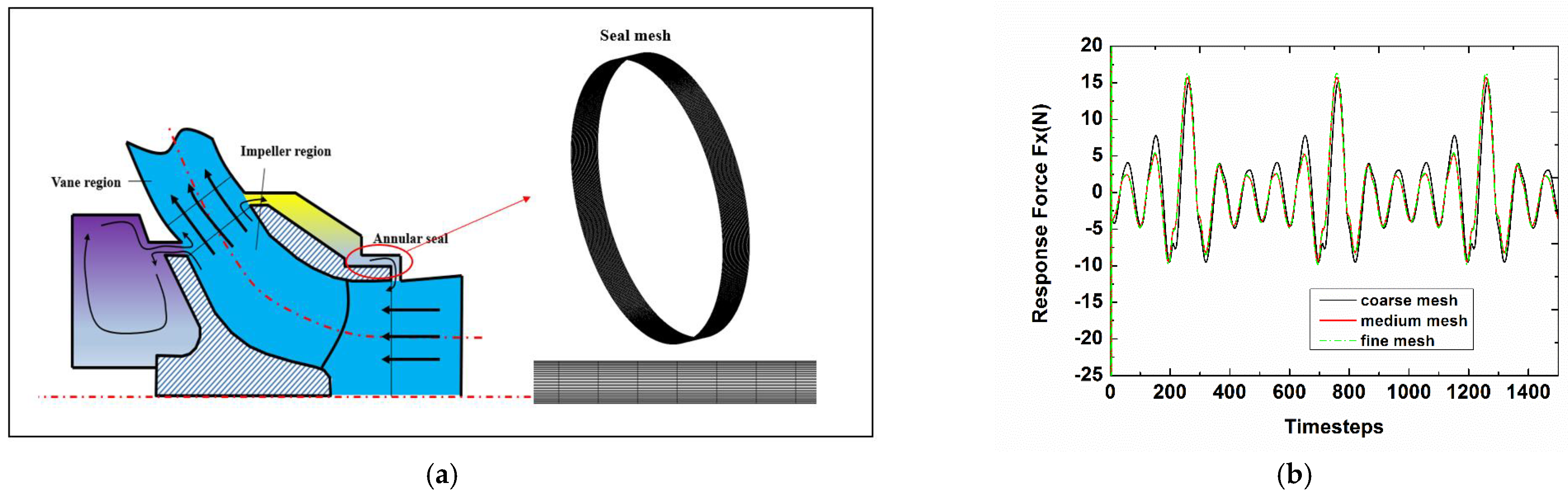
2.1. Seal Geometry and Computational Model

In real operational conditions, the eccentric movement of the sealed rotor will cause the uneven distribution of the fluid pressure at the sealing gap, resulting in fluid self-excitation. The annular seal between stator and rotor substantively acts as a bearing, which affects the rotordynamic characteristic of the turbomachinery rotor system, as show in Figure 1.
In this work, a 3-D unsteady numerical method combined with the multiple-frequency elliptical rotor whirling orbit model was utilized for investigating the rotordynamic characteristics of the 1400-MW canned nuclear coolant pump annular seal at different inflow distortion conditions. The seal geometry referred to the nuclear main pump scale hydraulic model [27] (on a scale of 1:2.5) designed by the team (see Table 1).
In this paper, the ANSYS ICEM CFD commercial software was employed to generate the full 3-D seal structured mesh for calculation because of the nonuniform response forces inside the annular seal. For the sake of investigating grid independence and how fine the structured mesh density is required for precisely predicting the rotordynamic characteristics, three types of mesh (coarse, medium and fine) were created. The number of nodes for the coarse mesh is 1.25 × 10⁶ with 1.15 × 10⁶ elements, while the size of the medium mesh and fine mesh is 2.31 × 10⁶ nodes with 2.16 × 10⁶ elements and 3.21 × 10⁶ nodes with 3.13 × 10⁶ elements, respectively. As shown in Figure 2b and in Table 2, there is a slight difference between the response force, inlet mass flow and total outlet pressure of the medium and fine meshes. Hence, the medium mesh was adopted for the following numerical investigation. The numerical parameter settings in detail are provided in Table 3.

2.2. Rotor Motion

In real operational conditions, an absolutely concentric rotating never occurs. On the contrary, the center C of the rotor usually whirls around the center O of the seal stator at the whirling speed Ω , as shown in Figure 3. In order to predict the frequency-dependent rotordynamic coefficients of the annular seal, the elliptical orbit whirling model for the rotor vibration was adopted in this work. Hence, the rotor is supposed to whirl around the center O in a periodic elliptical orbit. At the same time, the rotor is spinning around the rotor center C. Therefore, for the rotor surface, the speed is the assembly of the rotor spinning speed ω and whirling speed Ω . Though the whirling orbit model with a single frequency is widely utilized to solve the annular seal rotordynamic coefficients, the multiple-frequency whirling orbit model is more suitable for obtaining the real rotordynamic characteristics. Moreover, the multiple-frequency whirling orbit model can greatly reduce the computational time compared to the single-frequency vibration. Therefore, for predicting a series of the frequency-dependent rotordynamic coefficients of the nuclear coolant pump annular seal, the multiple-frequency elliptical rotor whirling orbit motion was utilized as the motion model in the present numerical analysis. The major axis of the elliptical whirling orbit is defined as the excitation direction. The rotor whirling motion Equations (1) and (2) are defined as harmonic functions with specific whirling amplitudes a and b, and multiple whirling frequencies Ω i = 2 π f i . For each frequency component, the whirling amplitudes are equally constant values and related to the seal clearance, a = 0.02 × s and b = 0.01 × s . The whirling frequencies f i were defined in the frequency range between 5 and 25 Hz. Therefore, the fundamental frequency f 1 = 5 Hz and the number of elliptical whirling orbit frequencies is N = 5. Figure 4 illustrates the multiple-frequency elliptical whirling orbit with a maximum peak vibration amplitude 3.2 × 10⁻⁵ m, which is 10% of the annular seal clearance. In this way, the solutions will capture the linear motion characteristics based on the small motion theory.
Equations of elliptical whirling orbit motion for the x-direction excitation:
X = a i = 1 N cos ( Ω i t ) ,   Y = b i = 1 N sin ( Ω i t )
Equations of elliptical whirling orbit motion for the y-direction excitation:
X = b i = 1 N cos ( Ω i t ) ,   Y = a i = 1 N sin ( Ω i t )

2.3. Rotordynamic Coefficients Solution Method

Based on the small motion theory, ignoring the added mass terms, the fluid-induced forces can be defined by the response force/seal motion model [28], as presented in Equation (3), which generates the relationship between the reaction-force and the rotor motion through direct force coefficients ( K x x ,   K y y ,   C x x ,   C y y ) and cross-coupled force coefficients ( K x y ,   K y x ,   C x y ,   C y x ).
[ F x F y ] = [ K x x ( Ω ) K x y ( Ω ) K y x ( Ω ) K y y ( Ω ) ] [ X Y ] + [ C x x ( Ω ) C x y ( Ω ) C y x ( Ω ) C y y ( Ω ) ] [ X ˙ Y ˙ ]  
Through the fast Fourier transform (FFT) method, Equation (3) can be derived in another form, as given in Equation (4), where F i j and D i j are the FFT of the time-dependent reaction-force and rotor whirling motion. Note that F i j , D i j and H i j are all complex numbers. Frequency-dependent force impedances H i j in Equations (5)–(8) are determined from Equation (5). The frequency-dependent rotordynamic coefficients K i j   and   C i j are solved by separating H i j into real and imaginary components, as defined in Equations (9)–(12).
[ F x x F y x F x y F y y ] = [ H x x H y x H x y H y y ] [ D x x D y x D x y D y y ]
Direct and cross-coupled force impedance for x-direction excitation:
H x x = ( F x x ) D y y ( F y x ) D x y D x x D y y D y x D x y
H x y = ( F x x ) D y x ( F y x ) D x x D x y D y x D y y D x x
Direct and cross-coupled force impedance for y-direction excitation:
H y y = ( F y y ) D x x ( F x y ) D y x D x x D y y D y x D x y
H y x = ( F y y ) D x y ( F x y ) D y y D x y D y x D y y D x x
Direct stiffness and damping coefficients for x-direction excitation:
{ K x x = Re ( H x x ) C x x = Im ( H x x ) / Ω
Cross-coupled stiffness and damping coefficients for x-direction excitation:
{ K x y = Re ( H x y ) C x y = Im ( H x y ) / Ω
Direct stiffness and damping coefficients for y-direction excitation:
{ K y y = Re ( H y y ) C y y = Im ( H y y ) / Ω
Cross-coupled stiffness and damping coefficients for y-direction excitation:
{ K y x = Re ( H y x ) C y x = Im ( H y x ) / Ω
Keff and Ceff are used to illustrate the rotordynamic performance of the seal, defined as Equation (13).
{ K e f f = K x x + C x y Ω C e f f = C x x K x y / Ω
Figure 5 shows a schematic diagram of the overall framework for solving the rotordynamic coefficients of the annular seal.

2.4. Numerical Method Validations

The reliability of the research results in this paper lies in whether the transient numerical calculation method can accurately obtain the fluid-exciting force when rotor whirling is simulated. The parameter data of seal geometries and operational conditions used for proving the numerical method available were provided by Marquette [29]. The seal clearance and radius were 0.1013 m and 38.15 m, respectively. The ratio of seal length to diameter was 0.457. In this operation, the pressure drops between inlet and out outlet was 4.17 MPa, with the seal rotor spinning at 105,520 rpm. Water supplied at 55.3 °C was used as the working medium. By using the ANSYS CFX11.0 commercial software, an unsteady solution combined with the moving mesh of the single-frequency whirling method was applied to obtain the time-varying exciting forces on the rotor surface. The standard κ - ε turbulence model was utilized to simulate the transient turbulence conditions of the entire annular seal flow. Moreover, the scalable logarithmic wall function was chosen to solve the flow characteristics near the wall. In addition to this, the high-resolution scheme was applied for the spatial discretization with the second-order backward Euler scheme adopted for transient term discretization. Static pressure and 5% turbulence intensity were defined at the entrance boundary with the averaged static pressure applied at the seal exhaust. In addition to its rotational speed specified at the rotor surface, the periodic circular whirling motion (Figure 3a) for x and y-directions of excitation displacements, shown in Figure 6 were also added in the transient solution. For the rotor, the eccentricity was selected to be 10% of the sealing clearance. The desirable convergence target of the transient solutions is that the RMS residuals of the momentum and mass equations and turbulence equations attain below 10−5, in addition, the response forces (Fx, Fy) on the rotor surface approaches steady periodical oscillation and the difference value between two adjoining vibration periods is desired to be less than 0.4%.
{ F r e = K c Ω ω + M ( Ω ω ) 2 F t e = k C Ω ω m ( Ω ω ) 2
Figure 7 shows the response forces (Fx, Fy, Fr, Ft) for the rotor surface during the transient solutions. The response forces are solved by integrating surface pressure and shear stresses in each timestep. The frequency-independent rotordynamic coefficients were solved by the curve-fitting method based on Equation (14). Figure 8 depicts experiment data and numerical prediction results of tangential impedance and radial impedance versus the precessional frequency ratio. Compared to experimental data published by Marquette [29], the cross-coupling stiffness, direct damping and cross-coupling damping listed in Table 4 are over predicted, while the direct stiffness is under predicted. In general, the agreement of the numerical results with the experimental data is reasonably good. It is verified that the transient numerical method combined with the moving mesh technology can effectively predict the rotordynamic characteristics of the seal.

2.5. Inflow Distortion

The majority of researchers investigated the effect of inlet preswirl, pressure ratio and whirling eccentricity on the rotordynamic characteristics of a seal system but ignored the effect of inflow distortion caused by blade loading and wake turbulence. Actually, as shown in Figure 9, the phenomenon of nonuniform pressure distribution at the outlet of the impeller is mostly caused by wake turbulence when the work medium flows through the blades. Subsequently, the nonuniform pressure distribution spreads through the chamber, finally inducing the inflow distortion of the annular seal, which affects the frequency-dependent rotordynamic characteristics. The exhaust flow from the impeller presents periodic nonuniformity in the circumferential direction. Previously, researchers [26] utilized harmonic functions to characterize the wake turbulence. In this paper, the inflow distortion patterns were defined as harmonic functions, including two important influence parameters that are impeller blades number m and pressure fluctuation ratio   λ . Three cases were designed for investigating the effect of inflow distortion on the rotordynamic coefficients of a 1400-MW canned nuclear coolant pump annular seal, as shown in in Table 5. Among these cases, Case 1 was commonly utilized in the research work about rotordynamic characteristics. Case 2 described the pressure fluctuation invariant with time, where the number of impeller blades is determined as m and the θ is a coordinate variable in cylindrical coordinates with the axis of impeller rotation determined as the Z-axis. Case 3 provided the time-varying inflow distortion, which is closer to the actual operational situation, where ω means the spinning speed of the rotor. Although the pressure distribution at the inlet of each case is different, the magnitude of average pressure is the same.

3. Results and Discussions

3.1. Rotordynamic Coefficients Results for Different Cases

In practice, there is a nonuniform pressure distribution instead of an even flow field with a constant pressure parameter at the entrance of the annular seal. In order to investigate the effect of inflow distortion patterns on the rotordynamic characteristics of the RCP annular seal, three transient computational cases were projected in the frequency range of 5–25 Hz with a 1485 rpm rotor speed. Figure 10 shows that the damping coefficients C x x , C x y and C e f f predicted by the present transient numerical method increase with the increasing whirling frequency, but the direct stiffness K x x , the cross-coupling stiffness K x y and the effective stiffness K e f f decrease. In addition, the rotordynamic coefficients predicted in Case 3 are almost equal to that in Case 1, while there is a larger difference between Cases 1 and 2. Generally, the rotordynamic coefficients obtained in Case 2 are less than that in Case 1, except for the direct damping C x x at the low frequency and the effective damping C e f f in the full frequency domain. In Figure 10e,f, the predicted effective coefficients in Cases 1 and 3 have similar variation trends and values, in comparison to the results in Case 2. The authors suggest that the small distinction between numerical results in Case 1 and Case 3 could be partly attributed to the constant term Δ P and the spinning speed ω in Case 3. Similar to that in Case 1, the two parameters in Case 3 lead to the time-averaged pressure distribution in each node at the entrance of the annular seal. Consequently, the approximate rotordynamic coefficients are solved in Cases 1 and 3 based on the similar response forces by integrating pressure over the rotor surface.
The above discussion shows that the spinning speed ω makes a dent in the effect of inflow distortion on the rotordynamic coefficients of the annular seal. With a higher spinning speed, there is smaller effects of the inflow distortion. In the limiting situations when the spinning speed ω = 0 is akin to Case 2 or when the time-averaged pressure distribution at the entrance of the annular seal is extremely nonuniform, the inflow distortion has an important effect on the rotordynamic characteristics of the RCP seal. In this work, the magnitude of the positive effective stiffness K e f f and damping C e f f decrease because of the inflow distortion of the annular seal, which may result in a risk of high vibration or even rotor stability. From the rotordynamic stability point of view, more attention should be focused on investigating the effect of inflow distortion on the rotordynamic characteristics of the seal system.

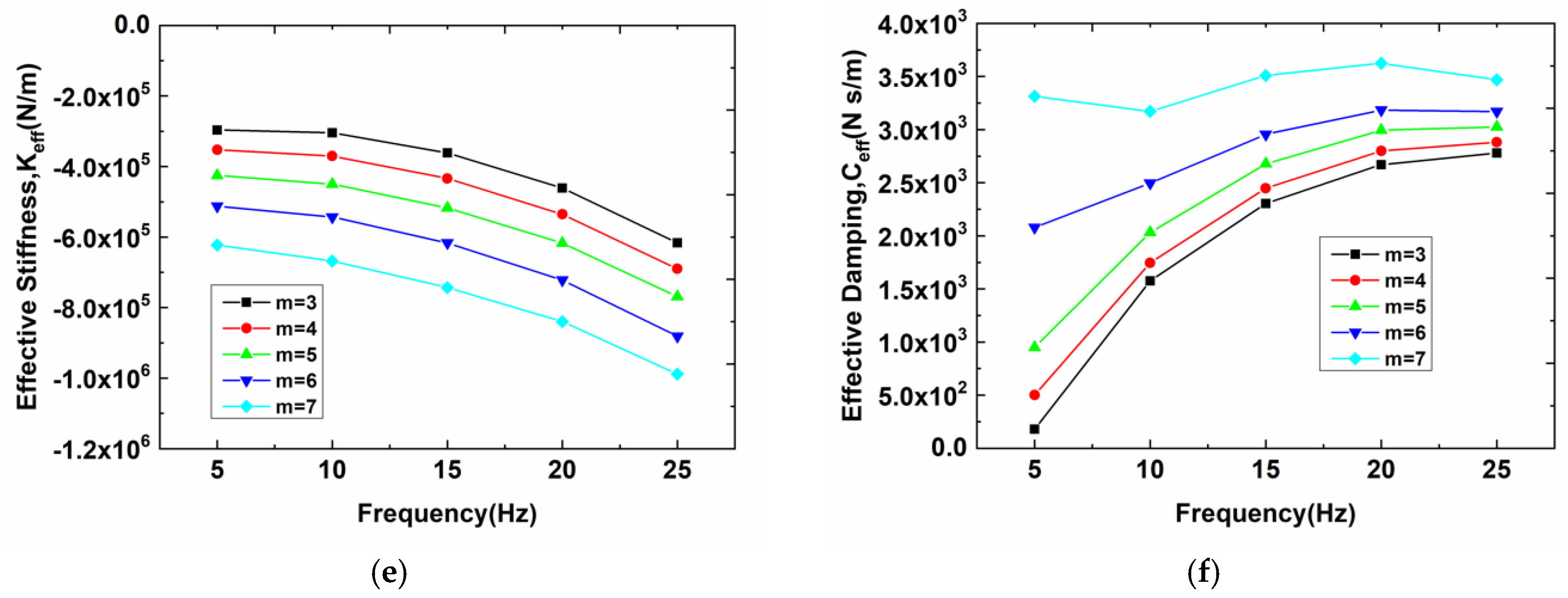
3.2. Effects of Impeller Blades Number

The above section has discussed the significant effect of inflow distortion on the rotordynamic characteristics of the annular seal. This section focuses on one of the inflow distortion factors, i.e., the impeller blades number m, which affects the rotordynamic characteristics of the annular seal. In these present numerical solutions, the number of impeller blades m is within the range [3,7] frequently selected to design the nuclear coolant pump.
Figure 11 depicts the predicted rotordynamic coefficients with five different blade numbers for the annular seal in Case 2. It is observed that there is an obvious trend of direct stiffness K x x , cross-coupling stiffness K x y , effective stiffness K e f f and effective damping C e f f versus impeller blade number m. The stiffness coefficients decrease with the increase of impeller blade number m, while the effective damping C e f f increases. For each impeller blade number, the stiffness coefficients decrease with the increasing whirling frequency, while the effective damping C e f f increases. Compared to the evident trend of the stiffness coefficients versus whirling frequency and impeller blade number, Figure 11b,d,f shows a more complex trend of the damping coefficients. As shown in Figure 11b, the direct damping C x x increases with the increasing whirling frequency when the impeller blade number m is below 5. However, with the impeller blade number increased above m = 5, the direct damping C x x gives gentle variation versus whirling frequency, which begins to show a trend independent of the whirling frequency. At the frequency of 25 Hz, the direct damping C x x decreases with the increasing impeller blade number m, while at the frequencies smaller than 25 Hz, the increasing blade number has a significant effect on the chaotic variation trend, especially at 5 Hz. Figure 11d gives the dependence of rotordynamic coefficients versus whirling frequency for the annular seal. For the frequencies larger than 10 Hz, the cross-coupling damping C x y decreasing with the increasing impeller blade number m presents a steady trend. Compared to these trends shown in Figure 11b, the results of effective damping C e f f in Figure 11f present a more obvious trend: it is independent of the whirling frequency when blade number m = 7.
In general, there is a general trend that the increasing blade number will increase the negative effective stiffness value, which significantly strengthens the rotor vibration. Apart from this, the effective damping C e f f increases as m increases, which can improve the rotor stability.

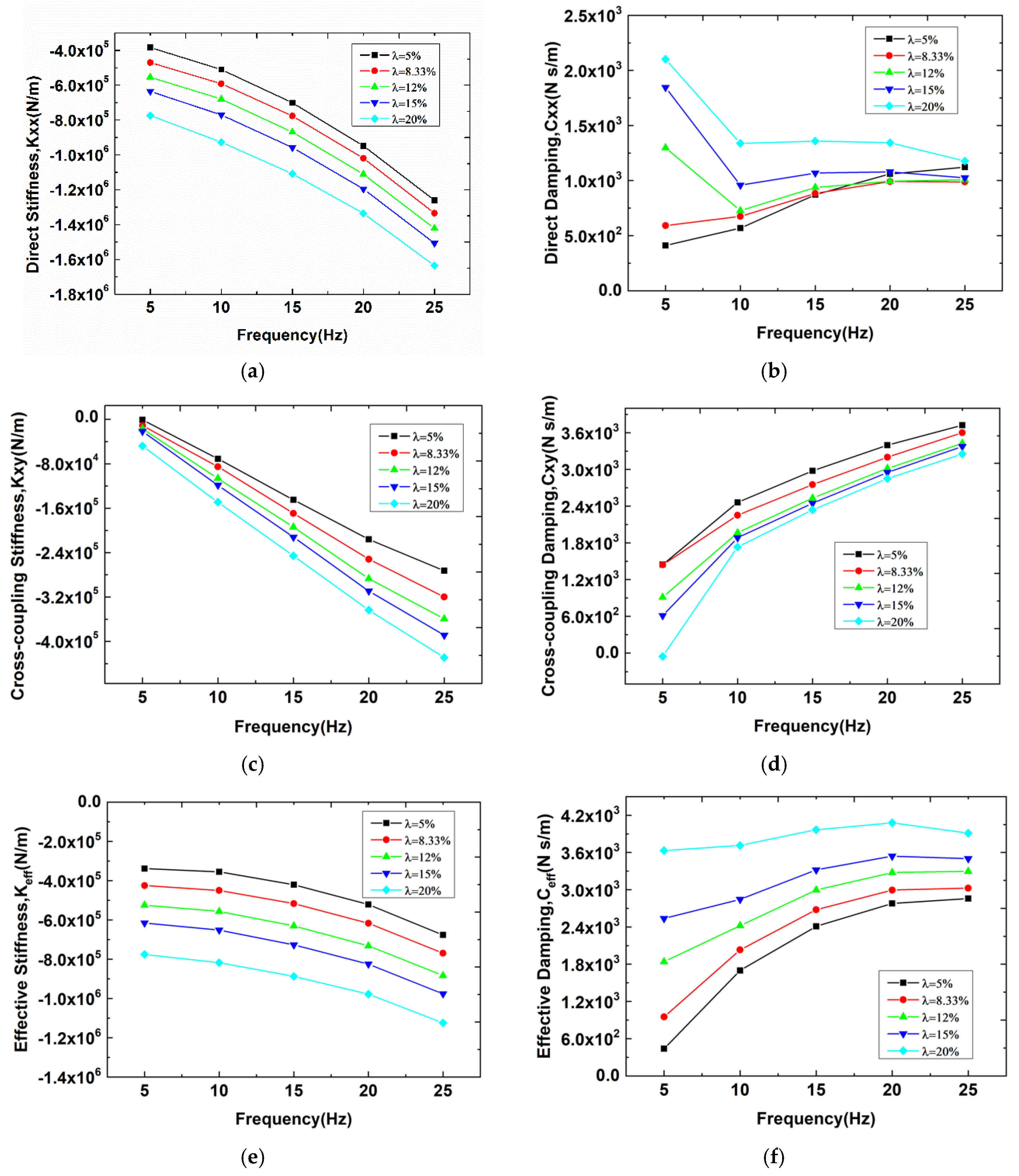
3.3. Effects of Pressure Fluctuation

The pressure fluctuation ratio λ , defined in Equation (15), was used to represent the inflow distortion intensity in this paper. In the present work, five pressure fluctuation ratios λ = 5%, 8.33%, 12 %, 15% and 20% were chosen to investigate the effect of pressure fluctuation in Case 2.
λ = Δ P P c o n s t a n t × 100 %
Figure 12 illustrates the rotordynamic coefficients versus whirling frequency for the annular seals with different pressure fluctuation ratios. The comparison of force coefficients illustrated in Figure 12 suggests that the rotordynamic coefficients decrease when the pressure fluctuation ratio increases from 5% to 20%, except for the damping coefficients. For each pressure fluctuation ratio λ , the stiffness coefficients decrease with the increasing whirling frequency, while the effective damping C e f f increases. The plots of direct damping C x x coefficients in Figure 12b show an interesting phenomenon that when the pressure fluctuation ratio λ is larger than 12%, the direct damping C x x first sharply decreases with the whirling frequency when it increases from 5 to 10 Hz, and then slightly changes with the increasing whirling frequency, which shows a trend independent of the whirling frequency. For the pressure fluctuation ratios λ   = 5% and λ   = 8.33%, Figure 12b presents dependent direct damping coefficient C x x increasing with the increasing whirling frequency. The plots of effective stiffness coefficient in Figure 12e suggest that with the increasing whirling frequency and the increasing pressure fluctuation ratio λ , the magnitude of negative coefficient K e f f increases, which results in a risk of the rotor misalignment problem. In Figure 12f, it is worthwhile noticing that the effective damping coefficient C e f f is more insensitive to the whirling frequency with the higher-pressure fluctuation ratio λ . Overall, the positive effective damping increases with an increase in pressure fluctuation ratio λ , which reduces the destabilizing forces in the rotor system.

3.4. Details of Inner Flow Field

By using the present CFD method, the entire flow field within the nuclear coolant pump annular seal is viewed to give insight into the rotor precession phenomenon. Figure 13 presents the whirling displacement of the rotor versus time and circumferential pressure distributions of the rotor at different times. There are obvious phenomena that the magnitude of overall pressure at the rotor surface in Case 2 is significantly greater than those in Cases 1 and 3. Though there is a big difference between the import conditions of Cases 1 and 3, the magnitude of overall pressure at the rotor surface in Case 3 is similar to that in Case 1. The reason for this phenomenon is that in the import condition of Case 3, the influence parameter ω (spinning speed) causes the peaks and troughs of the pressure distribution to migrate in the circumferential direction over time, which can reduce unevenness in the circumferential direction. It can be observed from Figure 13e that when t = 0.3 s (with the maximum displacement of the rotor), the circumferential pressure nonuniformity caused by rotor eccentricity will be coupled with the inflow distortion, which aggravates the nonuniformity of the pressure distribution on the rotor surface.
Figure 14 illustrates the transient static pressure distributions and the phasor diagram of the reaction force at the meridional cross-section of the annular seal in three different cases for x excitation and t = 0.2 s. In addition, the time-monitor signals of the rotor orbit position and the whirling direction are indicated as a blue circular patterning with a black straight arrow. As shown in Figure 14, the position of relatively higher pressure corresponds to the direction of resp onse force F in Case 1, while the number of peak pressures corresponds to the impeller blade number on the effect of inflow distortion in Cases 2 and 3. For each case, the force component Fr is 180 degrees out of phase with the rotor motion position, while the force component Ft is consistent with the rotor whirling velocity. This illustrates the nuclear coolant pump annular seal possesses negative effective stiffness and positive effective damping. The magnitudes of Fr and Ft in Figure 14a,c show almost identical values. While compared to the results in Figure 14a, the magnitudes of Fr and Ft in Figure 14b obviously increase. This can be used to explain that the effective stiffness and effective damping in Cases 1 and 3 have almost identical values, while the absolute value of effective coefficients for Case 2 are larger than that for Case 3. These conclusions are consistent with the observations in Figure 10.

4. Conclusions

The majority of researchers use uniform inlet conditions to study the dynamic characteristics of seals in turbomachinery systems. However, in real operational conditions, seal inlet conditions are not uniform due to upstream influences. In the current study, a three-dimensional transient solution based on a multi-frequency elliptical whirling orbit model was utilized to study the effect of inflow distortion on the rotordynamic characteristics of the 1400-MW RCP seal. The rotordynamic coefficients and inner flow field were numerically predicted for three inflow distortion pattern cases. In this paper, several conclusions can be obtained by analyzing the numerical computational results.
The results suggest that compared with the magnitudes of negative effective stiffness K e f f in Case 1, those in Cases 2 and 3 both decrease, with the maximum reduction up to 169% and 8.6%, respectively. In addition, the positive effective damping C e f f in Case 2 has a maximum increase of up to 259% compared with that in Case 1, while there is a minor difference between that in Case 1 and Case 3. In general, the inflow distortion has a significant effect on destabilizing the rotor system.
With the increasing impeller blade number in Case 2, an obvious decrease in the magnitudes of the negative effective stiffness K e f f results in a risk of rotor misalignment. In addition, the larger impeller blade number will also lead to higher positive effective damping C e f f , which threatens the rotor stability. These results provide theoretical guidance for engineers who choose impellers with as few blades as possible, which is beneficial to the operation safety of RCP.
Compared to the effect of impeller blade number on the rotordynamic characteristics in Case 2, another influencing factor of inflow distortion (pressure fluctuation ratio) has a similar effect. That is, with an increasing pressure fluctuation ratio, the negative stiffness K e f f   decreases and the effective damping C e f f increases compared to the whirling frequencies. This suggests that the higher the pressure fluctuation ratio, the more unstable the rotor system is. In summary, the inflow distortion plays a role in the effect on the rotor instability of the nuclear coolant pump annular seal. The potential danger caused by inflow distortion cannot be ignored.

Author Contributions

Conceptualization, L.Z., X.W. and H.L.; methodology, L.Z. and X.W.; validation, L.Z.; formal analysis, L.Z. and J.X.; investigation, L.Z.; resources, L.Z.; data curation, J.X.; writing—original draft preparation, L.Z.; writing—review and editing, L.Z. and H.L.; visualization, L.Z; supervision, X.W.; project administration, X.W.; funding acquisition, X.W. All authors have read and agreed to the published version of the manuscript.

Funding

The authors appreciate the financial support from the Research and Innovation in Science and Technology Project of Liaoning Province (2019JH1-10100024), the National Natural Science Foundation of China (52005074), and the Fundamental Research Funds for the Central Universities (DUT19RC(3)070), and the Collaborative Innovation Center of Major Machine Manufacturing in Liaoning.

Data Availability Statement

Not applicable.

Conflicts of Interest

The authors declare no conflict of interest.

Nomenclatures

aMajor axis of the elliptical orbit (m)
bMinor axis of the elliptical orbit (m)
cCross-coupling damping (N-s/m2)
CDirect damping (N-s/m2)
CxxDirect damping in x-direction (N-s/m2)
CxyCross-coupling damping in x-direction (N-s/m2)
CyyDirect damping in y-direction (N-s/m2)
CyxCross-coupling damping in y-direction (N-s/m2)
CeffEffective damping (N-s/m2)
DxxRotor orbit motion in x-direction for x-direction excitation (m)
DxyRotor orbit motion in y-direction for x-direction excitation (m)
DyyRotor orbit motion in y-direction for y-direction excitation (m)
DyxRotor orbit motion in x-direction for y-direction excitation (m)
FxxRotor reaction force in x-direction for x-direction excitation (N)
FxyRotor reaction force in y-direction for x-direction excitation (N)
FyyRotor reaction force in y-direction for y-direction excitation (N)
FyxRotor reaction force in y-direction for x-direction excitation (N)
FrRotor reaction force in radial direction (N)
FtRotor reaction force in tangential direction (N)
HxxDirect force impedance in x-direction (N/m)
HxyCross-coupling force impedance in x-direction (N/m)
HyyDirect force impedance in y-direction (N/m)
HyxCross-coupling force impedance in y-direction (N/m)
kCross-coupling stiffness (N/m)
KDirect stiffness (N/m)
KxxDirect stiffness in x-direction (N/m)
KxyCross-coupling stiffness in x-direction (N/m)
KyyDirect stiffness in y-direction (N/m)
KyxCross-coupling stiffness in y-direction (N/m)
KeffEffective direct stiffness (N-s/m2)
mImpeller blade number
n Rotational speed (rpm)
P i n Inlet pressure (Pa)
Δ P Pressure fluctuation (Pa)
PFRPrecessional frequency ratio Ω / ω
RSeal radius (mm)
eRotor eccentricity(m)
sSealing clearance (m)
fRotor whirling frequency (Hz)
ω Rotor spinning speed (rad/s)
Ω Rotor whirling speed (rad/s)
λ Pressure fluctuation ratio (%)

References

  1. Vance, J.M.; Zeidan, F.Y.; Murphy, B.G. Machinery Vibration and Rotordynamics, 1st ed.; Wiley: Hoboken, NJ, USA, 2010. [Google Scholar]
  2. Jiang, Q.; Zhai, L.; Wang, L.; Wu, Z. Fluid-Structure Interaction Analysis on Turbulent Annular Seals of Centrifugal Pumps during Transient Process. Math. Probl. Eng. 2011, 2011, 929574. [Google Scholar] [CrossRef]
  3. Armstrong, J.; Perricone, F. Turbine Instability Solution-Honeycomb Seals. 1996. Available online: https://oaktrust.library.tamu.edu/bitstream/handle/1969.1/163441/T2547-56.pdf?sequence=1&isAllowed=y (accessed on 17 December 2021).
  4. Thomas, H.J. Instable Eigenschwingungen von Turbine-Nlaufern, Angefaucht Durch die Spaltstromungen Stopfbuschsen un Beschaufelungen. 1958. Available online: https://ci.nii.ac.jp/naid/20001276617/#cit (accessed on 17 December 2021).
  5. Black, H.F. Effects of Hydraulic Forces in Annular Pressure Seals on the Vibrations of Centrifugal Pump Rotors. J. Mech. Eng. Sci. 1969, 11, 206–213. [Google Scholar] [CrossRef]
  6. Childs, D.W. Finite-Length Solutions for Rotordynamic Coefficients of Turbulent Annular Seals. J. Lubr. Technol. 1983, 105, 437–444. [Google Scholar] [CrossRef]
  7. Antunes, J.; Axisa, F.; Grunenwald, T. Dynamics of Rotors Immersed in Eccentric Annular Flow. Part 1: Theory. J. Fluids Struct. 1996, 10, 893–918. [Google Scholar] [CrossRef]
  8. Hirs, G.G. Fundamentals of a Bulk-Flow Theory for Turbulent Lubricant Films. Ph.D. Thesis, Delft University of Technology, Delft, Holland, July 1970. [Google Scholar]
  9. Nelson, C.C. Rotordynamic coefficients for compressible flow in tapered annular seals. J. Tribol. 1985, 107, 318–325. [Google Scholar] [CrossRef]
  10. Zhai, L.; Chi, Z.; Guo, J.; Zhang, Z.; Zhu, Z. Theoretical Solutions for Dynamic Characteristics of Liquid Annular Seals with Herringbone Grooves on the Stator Based on Bulk-Flow Theory. Sci. Technol. Nucl. Install. 2018, 2018, 9412154. [Google Scholar] [CrossRef] [Green Version]
  11. Wang, W.; Liu, Y.; Jiang, P.; Chen, H. Numerical analysis of leakage flow through two labyrinth seals. J. Hydrodyn. Ser. B. 2007, 19, 107–112. [Google Scholar] [CrossRef]
  12. Zhang, J.; Yuan, S.; Fu, Y.; Fang, Y. A numerical simulation of 3-D inner flow in up-stream pumping mechanical seal. J. Hydrodyn. 2006, 18, 572–577. [Google Scholar] [CrossRef]
  13. Mortazavi, F. CFD-Based Impeller and Seal Rotordynamic Forces. Ph.D. Thesis, Texas A & M University, College Station, TX, USA, December 2018. [Google Scholar]
  14. Moor, J.J. Three-dimensional CFD rotordynamic analysis of gas labyrinth seals. J. Vib. Acoust. 2003, 125, 427–433. [Google Scholar] [CrossRef]
  15. Chochua, G.; Soulas, T.A. Numerical modeling of rotordynamic coefficients for deliberately roughened stator gas annular seals. J. Tribol. 2007, 129, 424–429. [Google Scholar] [CrossRef]
  16. Li, J.; Li, Z.; Feng, Z. Investigations on the Rotordynamic Coefficients of Pocket Damper Seals Using the Multifrequency, One-Dimensional, Whirling Orbit Model and RANS Solutions. In Proceedings of the Journal of the ASME Turbo Expo 2012: Turbine Technical Conference and Exposition, Copenhagen, Denmark, 11–15 June 2012. [Google Scholar]
  17. Cao, L.; Wang, J.; Li, P.; Li, Y. Numerical analysis on steam exciting force caused by rotor eccentricity. Shock. Vib. 2017, 2017, 8602965. [Google Scholar] [CrossRef] [Green Version]
  18. Li, Z.; Li, J.; Feng, Z. Labyrinth seal rotordynamic characteristics part I: Operational conditions effects. J. Propuls. Power 2016, 32, 1199–1211. [Google Scholar] [CrossRef]
  19. Li, Z.; Li, J.; Feng, Z. Labyrinth seal rotordynamic characteristics part II: Geometrical parameter effects. J. Propuls. Power 2016, 32, 1281–1291. [Google Scholar] [CrossRef]
  20. Subramanian, S.; Sekhar, A.S.; Prasad, B.V.S.S.S. Rotordynamic characteristics of rotating labyrinth gas turbine seal with centrifugal growth. Tribol. Int. 2016, 97, 349–359. [Google Scholar] [CrossRef]
  21. Childs, D.W.; Mclean, J.E.; Zhang, M.; Arthur, S.P. Rotordynamic performance of a negative-swirl brake for a tooth-on-stator labyrinth seal. J. Eng. Gas Turbines Power 2016, 138, 062505. [Google Scholar] [CrossRef]
  22. Zhang, M.; Childs, D.W.; Tran, D.L.; Shrestha, H. Clearance Effects on Rotordynamic Performance of a Long Smooth Seal with Two-Phase, Mainly-Air Mixtures. J. Eng. Gas Turbines Power 2019, 141, 012502. [Google Scholar] [CrossRef]
  23. Tran, D.L.; Childs, D.W.; Shrestha, H.; Zhang, M. Preswirl and Mixed-Flow (Mainly Liquid) Effects on Rotordynamic Performance of a Long (L/D = 0.75) Smooth Seal. J. Eng. Gas Turbines Power 2020, 142, 031012. [Google Scholar] [CrossRef]
  24. Lee, K.H.; Ha, T.W. Analysis of hybrid brush seal rotordynamic coefficients according to position of brush and clearance using 3D CFD. Int. J. Fluid Mach. Syst. 2020, 13, 90–102. [Google Scholar] [CrossRef]
  25. Tsukuda, T.; Hirano, T.; Watson, C.; Morgtan, N.R.; Weaver, B.K.; Wood, H.G. A numerical investigation of the effect of inlet preswirl ratio on rotordynamic characteristics of labyrinth seal. J. Eng. Gas Turbines Power 2018, 140, 082506. [Google Scholar] [CrossRef]
  26. Zhang, X.; Wang, P.; Ruan, X.; Xu, Z.; Fu, X. Analysis of pressure pulsation induced by rotor-stator interaction in nuclear reactor coolant pump. Shock. Vib. 2017, 2017, 1–18. [Google Scholar] [CrossRef] [Green Version]
  27. Zhou, F.; Wang, X. Effects of staggered blades on the hydraulic characteristics of a 1400-MW canned nuclear coolant pump. Adv. Mech. Eng. 2016, 8. [Google Scholar] [CrossRef] [Green Version]
  28. Childs, D.W. Turbomachinery Rotordynamics: Phenomena, Modeling, and Analysis, 1st ed.; Wiley-Interscience: Hoboken, NJ, USA, 1993. [Google Scholar]
  29. Marquette, O. Experimental versus Theoretical Comparison of the Static and Dynamic Characteristics of One Smooth and Two Grooved Liquid Annulas Seals with l/d of 0.457; Technical Report No. TL-SEAL-5-95; Turbomachinery Laboratory, Texas A&M University System: College Station, TX, USA, 1995. [Google Scholar]
Figure 1. Schematic diagram of the annular seal rotordynamic characteristics.
Machines 10 00065 g001
Figure 2. (a) Seal mesh; (b) Plots of mesh independence verification.
Machines 10 00065 g002
Figure 3. Schematic diagram of the elliptical whirling orbit model at a single frequency for (a) the x-direction excitation and (b) the y-direction excitation.
Machines 10 00065 g003
Figure 4. (a) Monitors of rotor motion (x-direction excitation); (b) Displacement of multiple-frequency whirling orbit modal (x-direction excitation).
Machines 10 00065 g004
Figure 5. Computational methodologies for the seal rotordynamic coefficients.
Machines 10 00065 g005
Figure 6. Single-frequency circular vibration displacement of the rotor (PFR = 1).
Machines 10 00065 g006
Figure 7. Response force on the rotor (PFR = 1).
Machines 10 00065 g007
Figure 8. Tangential impedance (a) and radial impedance (b) curves for the annular seal.
Machines 10 00065 g008
Figure 9. Sketch diagram of wake turbulence affecting inflow distortion of the annular seal. (a) Meridian plane (b) 3-D model.
Machines 10 00065 g009
Figure 10. (a) Direct stiffness Kxx, (b) direct damping Cxx, (c) cross-coupling stiffness Kxy, (d) cross-coupling damping Cxy, (e) effective stiffness Keff and (f) effective damping Ceff of the annular seal with impeller blades number m = 5.
Machines 10 00065 g010
Figure 11. Direct stiffness Kxx (a), direct damping Cxx (b), cross-coupling stiffness Kxy (c), cross-coupling damping Cxy (d), effective stiffness Keff (e) and effective damping Ceff (f) of the annular seal in Case 2 ( Δ P = 4000 Pa).
Machines 10 00065 g011aMachines 10 00065 g011b
Figure 12. Direct stiffness Kxx (a), direct damping Cxx (b), cross-coupling stiffness Kxy (c), cross-coupling damping Cxy (d), effective stiffness Keff (e) and effective damping Ceff (f) of the annular seal in Case 2 (impeller blades number m = 5).
Machines 10 00065 g012
Figure 13. (a) Monitors of rotor motion (x-direction excitation); (be) Circumferential pressure distributions of the rotor at different times.
Machines 10 00065 g013
Figure 14. Static pressure contours in the meridional cross section of the annular seal in (a) Cases 1, (b) 2 and (c) 3 (x excitation, t = 0.2 s, m = 5).
Machines 10 00065 g014
Table 1. Seal geometry of the 1400-MW canned nuclear coolant pump scale hydraulic model [27].
ParameterNomenclatureValue
Seal clearance (mm)s0.32
Seal radius (mm)R140
Ratio of seal length to diameterφ0.107
Rotational speed (rpm)n1485
Table 2. Mesh independence verification.
Type of Mesh Coarse MeshMedium MeshFine Mesh
Inlet mass flow (kg/s)1.2051.1941.193
Outlet total pressure (Pa)57,59456,95856,911
Table 3. Numerical parameter settings.
Solution TypeTransient
FluidWater
Computational method Time marching method
Turbulence model Standard   κ - ε model with scalable log wall function
Discretization schemeHigh resolution
Mesh motionMesh deformation
Yplus≤19
Frequency (Hz)5, 10, 15, 20, 25
Wall propertiesSmooth surface
Eccentric ratio10%
Timesteps (s)0.0004 s
Table 4. Rotordynamic coefficients of experimental data and numerical results.
K(MN/m)k(MN/m)C(MNs/m)c(MNs/m)
Experiment18.79.6220.55.37
CFD17.912.325.46.17
Table 5. Design Cases.
Design CasesCase 1Case 2Case 3
Inlet pressure conditions P i n = P c o n s t a n t P i n = P c o n s t a n t + Δ P · sin ( m · θ ) P i n = P c o n s t a n t + Δ P · sin ( m · θ + ω t )
Schematic diagram of the pressure cloud Machines 10 00065 i001 Machines 10 00065 i002 Machines 10 00065 i003
Publisher’s Note: MDPI stays neutral with regard to jurisdictional claims in published maps and institutional affiliations.

