Article

Proposed Shaft Coupling Based on RPRRR Mechanism: Positional Analysis and Consequences

by
Stelian Alaci
1,*,
Ioan Doroftei
2,
Florina-Carmen Ciornei
1,
Ionut-Cristian Romanu
1,
Toma-Marian Ciocirlan
1 and
Mariana-Catalina Ciornei
3,4,*
1
Mechanics and Technologies Department, “Stefan cel Mare” University of Suceava, 720229 Suceava, Romania
2
Mechanical Engineering, Mechatronics and Robotics Department, “Gheorghe Asachi” Technical University, 700050 Iasi, Romania
3
Physiology Department, “Carol Davila” University of Medicine and Pharmacy, 020021 Bucharest, Romania
4
Faculty of Medical Engineering, University “Politehnica” of Bucharest, 060042 București, Romania
*
Authors to whom correspondence should be addressed.
Axioms 2023, 12(7), 707; https://doi.org/10.3390/axioms12070707
Submission received: 9 June 2023 / Revised: 14 July 2023 / Accepted: 18 July 2023 / Published: 20 July 2023
(This article belongs to the Special Issue Applied Mathematics and Information Sciences)

Abstract

:
This study proposes a solution for the transmission of rotation motion between two shafts with crossed directions. For constructive simplicity, the solutions including the planar pair were preferred and, from the two variants, namely structurally symmetric, revolute–planar–revolute (RPR), or asymmetric RRP, the last was selected. The resulting solution, RPRRR, is a non-Denavit–Hartenberg (non-D–H) mechanism. The D–H methodology is laborious since the structure of the equivalent mechanism is more complex than the actual one. For this reason, in the present paper, the kinematic analysis of the mechanism uses geometrical conditions of existence of the planar pair. The system is solved analytically and two main conclusions result: for a set of constructive data and a stipulated position of the driving element, two different assembling positions exist and a rotation motion occurs in the final revolute joint, but in the internal revolute pairs, the motion is oscillatory. The correctness of the theoretical results was corroborated by a CATIA model. The mechanism was also constructed and smooth running was noticed. Two main concerns were considered for the design of the mechanism: avoiding mechanical interference between the elements and estimating the stresses and deformations.

1. Introduction

One of the key objectives of the Theory of Machines and Mechanisms is to propose solutions for the transmission of motion between two elements—driving and driven—belonging to a mechanical structure [1]. Regarding the motion of the driving element, it should be as simple as possible [2,3], such as rotation or sliding for most of cases, depending on the type of the actuating motor; but the motion of the final element can be from simple to complex [4]. We must emphasize that the evolution of mathematics was at least spectacular in the last century and notions which seemed to be pointless proved to be applicable for everyday life. Can be reminded here the theory of distributions [5], fractional derivative [6], matrix analysis [7], chaos theory [8], etc. To the above considerations, we can add Gaudi’s observation [9] that in nature there are no straight lines, a remark that highlights the nonlinear character of our world, evidenced by rather different topics: non-linear vibrations [10], green energy [11], semiconductor materials [12], dynamics of non-Newtonian fluids [13], music [14], sports [15], and so on. The same spectacular development of analysis methods was achieved in the domain of the spatial mechanisms theory. We can mention the screw theory [16,17,18], the dual numbers theory [19], the quaternions algebra [20], the dual quaternions method [21], and the tensor matrix method [22,23].
Two main directions are met in engineering applications: either the final element belongs to a mechanism and therefore the kinematics will depend on the motion of the driving element and on the constructive parameters of the mechanism, or the final element appertains to a robotic structure wherein the binary elements present a simple shape [24,25,26] (open kinematic chain) and the motion of the final element is ensured by the action of multiple driving pairs from the structure of the robot [27]—with the well-known examples of multiple-axes CNC machines [28,29] and medical devices and robots [30,31,32,33,34,35,36]. Contrasting with the robotic kinematic chain, in the case of mechanisms, the task of obtaining an imposed motion law of the final element is more difficult due to the fact that the driving element performs a simple motion. Here, the project design engineer must choose a certain structure for the intermediate coupling chain [37];moreover, they must perform the dimensional optimization for the elements from the chosen structure [38,39,40], with the aim of ensuring for the driven element the imposed law of motion at a specified precision. When the transmission of rotation motion between two shafts with crossed axes is desired [41,42], the direct coupling of the shafts represents the simplest structural solution. A simple structural calculus reveals that a class 1 pair must be created between the two shafts, materialized by a Hertzian point contact [43,44,45]. To this class of mechanisms belong the cam mechanisms [46] and the gear mechanisms [47,48,49,50,51] (which are particular cases of cam mechanisms). The coupling pair ensures five simple, possible motions: sliding in the common tangent plane after two directions and rotations, two about two axes from the tangent plane and one about an axis normal to this plane. The solution is extremely simple from a structural point of view but, regarding functional aspects, it has as main disadvantages: high contact stresses—which produce wear and energy losses due to friction [52,53,54] and contact hysteresis [55]—and the complicated geometries of the elements. A frequently utilized compromise in the kinematical analysis of spatial mechanisms consists in replacing the class 1 pair with an equivalent kinematic chain, constructed by elements joined with pairs of lower mobility, usually lower pairs (cylindrical, spherical, or planar) [56,57,58]. The case in which the sphere–plane contact from a tripodic mechanism [59,60,61,62] was replaced by a binary element that makes the initial elements a planar pair and a spherical pair is presented in [63]. Another example is presented in [64], where the swash plate mechanism was studied by two kinematic analysis methods. The first manner considers the actual mechanism and applies the geometrical conditions of definition for the sphere–plane pair. The second manner studies an equivalent mechanism of Denavit–Hartenberg (D-H) type [65], obtained as a result of replacing the class 1 pair with a fictive kinematical chain containing only binary elements joined by cylindrical pairs (rotation or prismatic) in D–H condition. Next, the D–H algorithm is applied for the kinematic analysis of the equivalent mechanism. The direct approach, based on the definition condition of the class 1 pair, is simpler than the method of ‘’homogenous operators’’ proposed by Denavit and Hartenberg [66], or other methods, equivalent to this, such as the dual matrix method [67,68], the method of dual quaternions [69,70], the screw theory [71], or other algorithms [72,73,74,75], which have the drawback of leading to cumbersome systems of trigonometric equations, difficult or impossible to solve analytically. This aspect can be overcome by using numerical methods; for example, Uicker et al. [76] present a matrix iterative procedure, fast convergent, based on the D–H algorithm.
Section 2 presents the theoretical basis upon which the structure of the proposed mechanism was chosen. For constructive simplicity, the solutions including the planar pair were preferred and, from the two variants, namely structurally symmetric, revolute–planar–revolute (RPR), or asymmetric RRP, the last was selected. The result is the mechanism for the coupling of the two crossed shafts is the RPRRR solution which, due to the presence of a planar pair that does not have a rotation axis with a well-stipulated direction, is a non-Denavit–Hartenberg (non-D–H) mechanism. The kinematical analysis is performed and the angular displacements from the revolute pairs and motions from the planar pair are found by analytical calculus. The next section, Section 3, presents both the models of the studied mechanism in Mathcad and CATIA but also the prototype constructed in the laboratory. The final section draws the main conclusions, from which the RPRRR mechanism is evidenced by its constructive simplicity, low fabrication costs, and high reliability due to the presence of lower pairs.

2. Materials and Methods

2.1. Structural Considerations

The transmission of rotation motion from a driving axis 1 to a driven axis n is a problem often encountered in engineering applications. Generally, the motion of the driving element is obtained from a motor with constant rotation velocity (combustion engine, electric motor, etc.). From a geometric point of view, the transmission of motion from the axis 1 to the axis n is characterized by the relative position between the input and output axes, expressed, for the most general case of crossed axes, by the twisted angle α 1 n and the length of the common normal a 1 n , as represented in Figure 1. The particular cases can be obtained from this general schematic: for α 1 n = 0 , the shafts are parallel and for a 1 n = 0, the shafts are intersecting. Between the input shaft (1) and the output shaft (n), a kinematic chain can be interposed in order to ensure the coupling. The characteristics of the intermediate coupling chain will influence the transmission ratio.
The quality of the motion transmission is considered by the transmission ratio i 1 n defined as
i 1 n = ω 1 ω n .
Dependent on the requirements imposed to the transmission ratio, the coupling between the driven and driving axis can be achieved directly or by means of an intermediate kinematic chain. Considering economic and functional criteria, the structure of the intermediate chain must contain a reduced number of elements—as less as possible—and the kinematic pairs between the elements should have a high reliability. For a transmission wherein a unique driving element exists, the mobility must be 1. In the general coupling case, the mobility is found using the following relation:
M f = 6 f n 1 k = f + 1 n k f c k
where n is the number of elements, including the immobile element, f is the family of the mechanism—defined as the number of common constraints—and c k is the number of kinematic pairs of the k class. Here, for the general case of a transmission of 0 family, for a direct coupling, in the relation (2) the number of elements is n = 3 and it also requires the presence of two revolute pair of class 5, for joining each of the two shafts to the ground. The relation (2) is applied for this case:
k = 1 5 k c k = 1
The unique solution of Equation (3) is k = 1 and, from here, the conclusion is that, for a general case, the coupling between two shafts must be accomplished by means of a class 1 pair. When a middle element is interposed between the two shafts, is results in n = 4 and the conclusion is as follows:
k = 1 5 k c k = 7 .
The 7 degrees of freedom can be placed in pairs of any class; therefore, the number of structural solutions increases. Akbil [61] presents the solution of tripod coupling with curve–curve-type contacts. The same structural solution is applied in [59] where point–surface-type contact is used for a tripod coupling. Evidently, by increasing to 2 the number of elements of the intermediate chain, the number of structural solutions will increase significantly, according to the following relation:
k = 1 5 k c k = 13
But knowing that the coupling kinematic chain contains 2 elements, it results that only three pairs will exist in the structure of the coupling kinematic chain. More than this, the relation (5) shows that the pairs of class c 1 or c 2 cannot be present in the structure of the coupling kinematic chain. This can be proved by examples; for instance, when accepting a class 2 pair, c 2 = 1 , the sum of classes of the other two pairs would be 11; therefore, the relation (5) cannot be satisfied because the maximum value of the class of a pair is 5. Therefore, the remaining possible structural solutions are
c 3 = 1 , c 4 = 0 , c 5 = 2 ;
c 3 = 0 , c 4 = 2 , c 5 = 1
The present work considers the first structural solution, relation (6), for which the kinematic chain contains a planar pair and two revolute pairs. This selected structural solution RPRRR is shown in Figure 2, using standard convention [77]. A particular feature to be mentioned about this mechanism is the parallelism of the axes of the revolute pairs, formed between the element 2 and the neighboring elements.

2.2. Kinematic Analysis of the Proposed Structural Solution

2.2.1. Principle of the Denavit–Hartenberg Methodology

Denavit and Hartenberg [65,66] proposed a solution for the kinematic analysis of spatial kinematic chains, based on the transformation of the coordinates of a point when a reference system is changed into another. In a general case, the coordinate transformation of a point from a Cartesian reference system into another coordinate system is described by a 3 × 3 type matrix, R 12 , that specifies the rotation of the axes of the new system with respect to the old ones and by a 3 × 1 type displacement vector, d 12 , that stipulates the position of the new origin O 2 with respect to the initial origin O 1 . The drawback of the method resides in the non-homogenous relations resulting from combining the transformations, when a third coordinate system is interposed between the initial and final frame:
x 1 y 1 z 1 = d 12 + R 12 x 2 y 2 z 2 .
Or, concentrated
x 2 = d 12 + R 12 x 2
The direct transformation from the frame 3 to system 1 and then, by means of the system 2, is written as
x 1 = d 13 + R 13 x 3 = d 12 + R 12 x 2 = d 12 + R 12 d 23 + R 23 x 3 = d 13 + R 12 d 23 + R 12 R 23 x 3 .
By identification, it results that
d 13 = d 12 + R 12 d 23 ; R 13 = R 12 R 23 .
The relation (11) confirms the non-homogeneous character of the relation of composition of displacements. As emphasized above, the concepts introduced in abstract mathematics proved to be applicable in modern engineering problems; in the case of spatial kinematics, Denavit and Hartenberg regarded the displacement from a coordinate system to another as a gliding in the plane x 4 = 1 from the quadri-dimensional space x 1 , x 2 , x 3 , x 4 , with gliding performed along a tri-dimensional sub-space in which the motion of the mechanism is completed. The transformation (relation 8) is now re-written as
x 1 y 1 z 1 1 = R 12 d 12 0 1 x 2 y 2 z 2 1 .
Or, in concentrated manner:
X 1 = T 12 X 2 .
The relations (4) can now be written as
X 1 = T 13 X 3 = T 12 T 23 X 3 = T 12 T 23 X 3 .
From here,
T 13 = T 12 T 23
Relation (15) attests to the fact that the artifice proposed by Denavit and Hartenberg, that is, the matrices describing the transformation of coordinates from a frame to another, is described using a matrix product respecting the succession in the order of transition from a frame to another and so the methodology was named the method of “homogenous operators”. The restriction imposed by the Denavit–Hartenberg (D–H) method consists in accepting the hypothesis that, in the structure of the kinematic chain, only cylindrical pairs C exist, with their particular forms of revolution R and translation T . The hypothesis permits that, by conforming the selection of coordinate frames attached to the elements of the mechanism, the relative position of two coordinate systems should be described by four parameters instead of six parameters required in the general case. In fact, each of the coordinate systems has the O z axis directed along the axis of the pair and the O x axis along the common normal of two consecutive axes. The transition from a frame to the next one is made by a roto-translation of parameters θ and s with respect to the current O z axis followed by a roto-translation of parameters α and a with respect to the O x axis of the succeeding frame. The two displacements are described by the operators:
Z θ , s = cos θ sin θ 0 0 sin θ cos θ 0 0 0 0 1 s 0 0 0 1
and
X α , a = 1 0 0 a 0 cos α sin α 0 0 sin α cos α 0 0 0 0 1 .
The coordinates are transformed from frame 2 into frame 1 with the following relation:
x 1 y 1 z 1 1 = Z θ 1 , s 1 X α 12 , a 12 x 2 y 2 z 2 1 .
or concentrated as
X 1 = Z θ 1 , s 1 X α 12 , a 12 X 2 .
Relation (18) was written according to the notation of axes by Yang [70]. Explicitly, the O x axes and the corresponding parameters α and a are denoted using two indices, corresponding to the two O z axes intersected by the current axis as common normal. Moreover, Yang proposes that, for cylindrical pairs, the displacements about the O z axis, ( θ ,   s ), also have two indices in order to specify the constant displacement. Thus, the matrix Z θ 1 , s 1 will represent the roto-translation motion from the cylindrical pair with as axis the line z 1 while Z θ 1 , s 11 will represent the rotation from the revolute pair and Z θ 11 , s 1 will represent the sliding from the prismatic pair.
Another advantage of the Denavit–Hartenberg methodology resides in the manner in which the inverse matrices of Z θ , s and X α , a are calculated, specifically by the plain change in the signs of the arguments. For instance, relation (18) can be written as
X 2 = Z θ 1 , s 1 X α 12 , a 12 1 X 1 = X α 12 , a 12 Z θ 1 , s 1 X 1 .
Apparently restrictive, due to the hypothesis requiring only cylindrical pairs in the structure of the kinematic chain (the D–H mechanism condition), the methodology can be applied to any kinematic chain after all the pairs, other than the cylindrical ones, which were structurally equivalated by successions of cylindrical pairs.
For the mechanism with the structural scheme presented in Figure 2, which is a non-D–H mechanism due to the incidence of the planar pair P, the method becomes appropriate after the planar pair P is equivalated by two prismatic pairs on different directions and a revolute pair with the normal direction for both of these directions. Thus, a kinematic chain consisting of 7 elements and 7 kinematic pairs of class 5 is obtained. The drawback of this equivalation is the fact that the matrix closure equations have a large number of factors (in the present case, this equation contains 7 factors of 7a type, so a product of 14 matrices) that lead to systems of cumbersome trigonometrical equations. These systems can rarely be solved analytically, only for particular situations, and in most of cases, they require numerical procedures for solving. Furthermore, the system of equations has multiple solutions, corresponding to all possible assembling positions of the kinematic chain, and a methodology for selecting the suitable assembling solutions is necessary. According to the mentioned problems, for the mechanism equivalent to the mechanism seen in Figure 2, a trigonometric system of six equations with six unknowns will be obtained, whose analytical solving is expected to be difficult or rather impossible.

2.2.2. Kinematic Analysis of the Proposed Mechanism

In order to avoid the issues related to these cumbersome systems of equations resulting from equivalations, the approach of the actual mechanism and the direct application of the conditions of definition of the planar pair are proposed. The planar pair can be realized in several modes. In the present case, the planar pair between elements 3 and 4 will exist when three non-colinear points from element 3 will also appertain to a plane attached to element 4. In Figure 3, the planar pair is made between the plane x 3 y 3 and the plane x 4 z 4 from element 4. The normal to the plane parallel to the axes y 3 and y 4 is denoted n 4 and the equation of the plane is
n 4 r r O = 0
where r is the position vector of a current point from the plane x 3 z 3 and r 0 is the position vector of a reference point from the same plane. A point from the plane x 3 y 3 belongs to the plane of Equation (8) if its coordinates verify Equation (8). For this purpose, the coordinates of a point belonging to element 3 are first brought in system 4, and after that, relation (8) is applied. The preferential selection of the orientation of the axes of the coordinate systems from Figure 3 simplifies the conditions of existence of the planar pair.
From Figure 3, it can be observed that a point from the plane x 3 z 3 will belong to the plane x 4 z 4 if, after the coordinate transformation, the following condition is satisfied:
y 4 = 0 .
It is noticed that, instead of a system of six equations, a system of three equations is obtained, from imposing the condition that Equation (21) (or Equation (22)) is satisfied by three distinct points. In order to obtain the transformation relation, the matrix describing the displacement of frame 3 is necessary. This cannot be obtained directly; a succession of D–H transformations must be applied in the following order:   4 1 2 3 . Specifically,
T 43 = Z θ 4 , s 4 X α 41 , a 41 Z θ 1 , s 1 X α 12 , a 12 Z θ 2 , s 2 X α 23 , a 23 Z θ 3 , s 3 .

2.2.3. Finding the Motions from the Revolute Pairs

Concerning the rotation motions from the pairs, the rotation from the driving pair θ 1 is known, while θ 2 , θ 3 , and θ 4 are unknown. Except for the angles ( θ k , k = 1 ,   4 ), all the other parameters from Equation (23) are constant, and some of them are zero:
s 2 = s 3 = s 4 = 0 ; a 12 = 0 ; α 01 = π 2 , α 12 = π 2 , α 23 = 0 .
The form of the equations of the system representing the condition of the planar pair can be simplified by choosing the three points in particular positions: the origin of the system 3 :   M 1 0 , 0 , 0 ; a point form the axis O x 3 :   M 2 x 3 , 0 , 0 ; and a point from the axis O z 3 : M 3 0 , 0 , z 3 . The relation of coordinate transformation of a point is applied for transition from system 3 to system 4:
x 4 y 4 z 4 1 = T 43 x 3 y 3 z 3 1
and for the points M 1 , M 2 ,   and   M 3 , the ordinate y 4 in frame 4 must be zero; thus, the following system of equations is obtained, using Mathcad software [78]:
a 23 cos θ 1 cos θ 2 sin θ 4 + a 23 cos α 41 sin θ 1 cos θ 2 cos θ 4 a 23 sin α 41 sin θ 2 cos θ 4 s 1 sin α 41 cos θ 4 + a 41 sin θ 4 = 0 x 3 cos θ 1 cos θ 2 cos θ 3 cos θ 4 + a 23 cos θ 1 cos θ 2 sin θ 4 + x 3 cos α 41 sin θ 1 cos θ 2 cos θ 3 cos θ 4 + a 23 sin θ 1 cos α 41 cos θ 2 cos θ 4 x 3 sin α 41 sin θ 2 cos θ 3 cos θ 4 a 23 cos θ 4 sin α 41 sin θ 2 x 3 cos θ 1 sin θ 2 sin θ 3 sin θ 4 x 3 cos α 41 sin θ 1 sin θ 2 sin θ 3 cos θ 4 x 3 sin α 41 cos θ 2 sin θ 3 cos θ 4 . s 1 sin α 41 cos θ 4 + a 41 sin θ 4 = 0 a 23 cos θ 1 cos θ 2 sin θ 4 + a 23 cos α 41 sin θ 1 cos θ 2 cos θ 4 a 23 sin α 41 sin θ 2 cos θ 4 . . + z 3 sin θ 1 sin θ 4 z 3 cos α 41 cos θ 1 cos θ 4 s 1 sin α 41 cos θ 4 + a 41 sin θ 4 = 0 .
System (26) takes a simpler form if the first equation is subtracted from the last two equations:
a 23 cos θ 1 cos θ 2 sin θ 4 + a 23 cos α 41 sin θ 1 cos θ 2 cos θ 4 a 23 sin α 41 sin θ 2 cos θ 4 s 1 sin α 41 cos θ 4 + a 41 sin θ 4 = 0 cos θ 1 cos θ 2 cos θ 3 sin θ 4 + cos α 41 sin θ 1 cos θ 2 cos θ 3 cos θ 4 sin α 41 sin θ 2 cos θ 3 cos θ 4 cos θ 1 sin θ 2 sin θ 3 sin θ 4 cos α 41 sin θ 1 sin θ 2 sin θ 3 cos θ 4 sin α 41 cos θ 2 sin θ 3 cos θ 4 = 0 sin θ 1 sin θ 4 cos α 41 cos θ 1 cos θ 4 = 0 .
The Equation (27) now have the following significance: the first equation imposes that the origin O 3 of the frame x 3 y 3 z 3 is positioned in the plane y 4 = 0 while the last two equations impose that the vectors M 1 M 2 ¯ and M 1 M 3 ¯ are parallel to the plane x 4 z 4 . The system (27) can be solved analytically:
θ 4 = atan cos α 41 c o s θ 1 s i n θ 1 + k π , k Z .
From a physical perspective, relation (28) does not have multiple solutions because the term k π does not alter the orientation of the plane of symmetry of the driven element but, at most, reverses the orientation of the normal n 4 . Relation (28) can be re-written as follows:
tan θ 4 = c o s a 41 t a n θ 1
and it is identical to the relation between the position parameters of the driven and driving elements of the Cardan transmission [1]. Relation (29) highlights the fact that the transmission ratio of the mechanism depends only on the constructive parameter α 41 , and the remaining constructive parameters of the mechanism must not satisfy special precision conditions. With a known θ 4 angle, from the first equation of the system (27), the angle θ 2 can be obtained, since the coefficients A θ 1 , B θ 1 ,   C θ 1 are now known; thus,
θ 2 = 2 atan B ( θ 1 ) ± B ( θ 1 ) 2 + A ( θ 1 ) 2 C ( θ 1 ) 2 A θ 1 C θ 1 + k π , k Z
where
A ( θ 1 ) = a 23 [ cos α 41 sin θ 1 cos θ 4 + sin θ 4 cos θ 1 ] ; B θ 1 = a 23 sin α 41 c o s θ 4 ; C θ 1 = a 41 sin θ 4 s 1 sin α 41 c o s θ 4 .
Equation (30) shows that, this time, from a physical point of view, for a stipulated position of the θ 1 angle of the driving element, there are two different assembling solutions for element 2.
The second Equation (27) makes it possible to find the rotation angle θ 3 with the following relation:
θ 3 ( θ 1 ) = atan [ P ( θ 1 ) / Q ( θ 1 ) ] + k π
where
P θ 1 = cos θ 1 cos θ 2 sin θ 4 + cos α 41 sin θ 1 cos θ 2 cos θ 4 sin α 41 sin θ 2 c o s θ 4 ;   Q θ 1 = cos θ 1 sin θ 2 sin θ 4 + cos α 41 sin θ 1 sin θ 2 cos θ 4 + sin α 41 cos θ 2 c o s θ 4 .
Relation (33) shows that, similar to element 3, a unique assembly solution exists. As a conclusion, for a given position of the driving element, only two different assembling positions of the mechanism exist, presented in Figure 4, with the remark that the plane faces of part 3 from the two variants must be coplanar. The mechanism was modelled in CATIA.
The variations in the angles θ 4 , θ 2 , and θ 3 as functions of the position angle of the driving element are presented in Figure 5, and it is noticed that the plot of the θ 4 angle presents jumps which are not actual, caused by the multiform character of the function atan ( x ) from relation (28). In these jump-points, as seen in Figure 5b,c, the mechanism passes from an assembling position to another, which is in fact impossible. To overcome this aspect, the θ 4 angle is redefined to eliminate the discontinuities. Ensuring a continuous variation of the θ 4 angle is reflected to the variation of the other two angles θ 2 and θ 3 , which will also not present discontinuities any more, as seen in Figure 6.
θ 4 = 0 θ 1 d θ 4 θ 1 d θ 1 d θ 1
Interesting consequences result from the analysis of the angular velocity variations, represented by the curves in Figure 7 and Figure 8. In Figure 7 is presented the variation in the angular velocity of the driven element θ ˙ 4 θ ˙ 1 obtained by the derivative of relation (29) with respect to time, both analytically and by modelling the mechanism in a specialised software. The two plots are similar and this fact confirms the correctness of relation (32). Additionally, the transmission ratio of the mechanism is the same as the one of a Cardan coupling having the same angle between axes, with the mention that the present coupling can transmit motion between crossed axes.
Regarding the motions from the other two revolute joints, when the two assembling solutions of the transmission are considered, the motions from pair 3 are identical but of opposite sign, but the motions from pair R 2 are completely different. This fact allows for selecting, from the two positions, the assembly variant for which the motion from pair R 2 leads to minimal dynamic effects, this choice not affecting the quality of transmission.
The magnitude of the rotational speed of the driving element is not relevant because the study of the mechanism was performed only through a kinematics point of view. The variations in all positional parameters from the kinematic pairs are proportional to this input driving rotational speed.

2.2.4. Finding the Motion from the Planar Pair
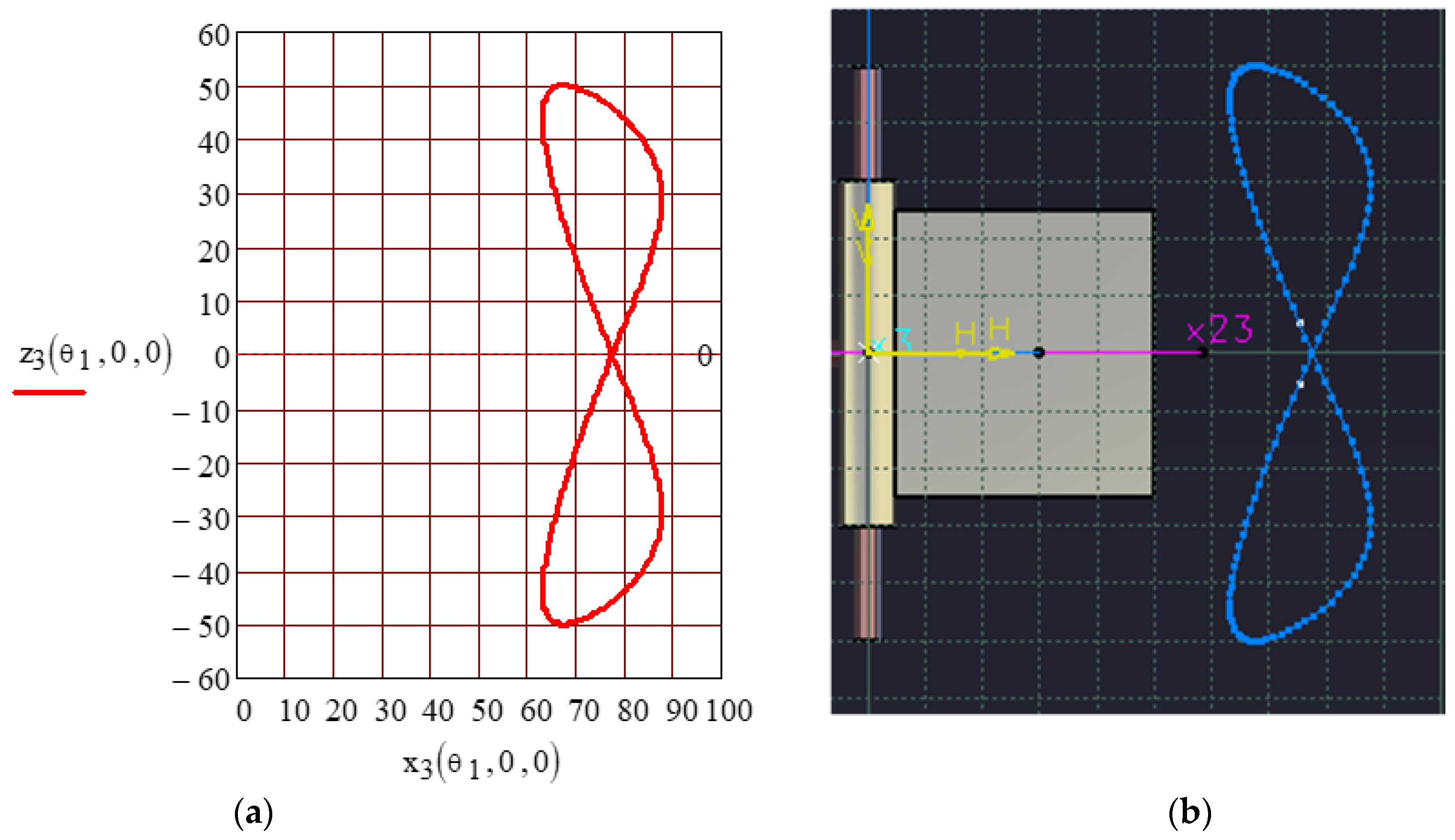
The planar pair is a c 3 joint (Class 3), so between the two elements forming the joint, there are 6 c k = 3 degrees of freedom, which permit for two translations in the plane of the pair and a rotation performed around an axis normal to the plane of the planar pair. The motion from the planar pair is fully characterized if the motion of a point from an element with respect to the other element and the variation in the angle between two straight lines from the contact plane, each line belonging to an element of the pair, are known. All these parameters should be stipulated as functions of the angle θ 1 of the driving element and of the constructive parameters of the mechanism. A point of coordinates M x 3 , 0 , z 3 from element 3 is considered, which describes in the coordinate system 4 a trajectory defined by the parametric equations:
x 4 0 z 4 1 = T 43 x 3 0 z 3 1
Relation (35) is developed; therefore, the parametric equations of the trajectory of a point from the plane x 3 z 3 in the plane x 4 z 4 are obtained:
x 4 ( θ 1 , x 3 , z 3 ) = x 3 [ cos θ 1 cos θ 2 cos θ 3 cos θ 4 cos α 41 sin θ 1 cos θ 2 cos θ 3 sin θ 4 + sin α 41 sin θ 2 cos θ 3 sin θ 4 . . . + cos α 41 sin θ 1 sin θ 2 sin θ 3 sin θ 4 cos θ 1 sin θ 2 sin θ 3 cos θ 4 + sin θ 3 sin θ 4 sin α 41 cos θ 2 ] . . . + z 3 [ sin θ 1 cos θ 4 + cos α 41 cos θ 1 sin θ 4 ] + s 1 sin α 41 sin θ 4 + a 41 cos θ 4 . . . + a 23 [ sin α 41 sin θ 2 sin θ 4 + cos θ 1 cos θ 2 cos θ 4 cos α 41 sin θ 1 cos θ 2 sin θ 4 ] z 4 ( θ 1 , x 3 , z 3 ) = x 3 [ sin α 41 sin θ 1 cos θ 2 cos θ 3 + cos α 41 sin θ 2 cos θ 3 sin θ 3 sin α 41 sin θ 1 sin θ 2 + sin θ 3 cos α 41 cos θ 2 ] . . . z 3 sin α 41 cos θ 1 + a 23 [ sin α 41 sin θ 1 cos θ 2 + cos α 41 sin θ 2 ] + s 1 cos α 41 .
In Figure 9, the trajectory of the origin of the system O 3 x 3 y 3 z 3 in the plane x 4 z 4 attached to element 4 is plotted, as in the particular case x 3 = 0 ;   z 3 = 0 in relation (36).
To find the rotation motion from the pair, it is sufficient to specify the variation in time of the angle between two straight lines belonging to the planes that form the planar pair. Aiming at this, the angle made by the versors i 3 and i 4 is found, considering that versor i 3 is defined by two points from the quadro-dimensional space by 1 0 0 1 T and 0 0 0 1 T and the projections of versor i 3 on the axes of the coordinate system 4 are given by the following relation:
i 3 i 4 i 3 j 4 i 3 k 4 0 = T 43 1 0 0 1 0 0 0 1 .
After the calculus is made, it results that
i 3 i 4 = cos θ 34 ( θ 1 ) = cos θ 1 cos θ 2 cos θ 3 cos θ 4 cos α 41 sin θ 1 cos θ 2 cos θ 3 sin θ 4 + sin α 41 sin θ 2 cos θ 3 sin θ 4 cos θ 1 sin θ 2 sin θ 3 cos θ 4 + cos α 41 sin θ 1 sin θ 2 sin θ 3 sin θ 4 + sin α 41 cos θ 2 sin θ 3 sin θ 4 i 3 j 4 = 0 i 3 k 4 = sin θ 34 ( θ 1 ) = sin α 41 sin θ 1 cos θ 2 cos θ 3 + cos α 41 sin θ 2 cos θ 3 sin α 41 sin θ 1 sin θ 2 sin θ 3 + cos α 41 cos θ 2 sin θ 3 .
Relation (38) allow for finding the rotation angle θ 34 θ 1 from the higher pair. It should be mentioned that, since the motion of the mechanism is periodic, with the angular period 2 π , an inverse trigonometrical function of two arguments is recommended to be used. With a known angle of rotation, the angular velocity is obtained with the following relation:
ω 43 = ω 1 d d θ 1 atan ( sinα 43 ) cosα 43 ) .
One must emphasize that, while the angular velocities ω 34 and ω 43 are identical but of opposite sign, it results from the definition of the two angles θ 34 and θ 43 that the relative motions of the origins O 3 and O 4 in the contact plane of the planar pair differ. To sustain this, based on relation (35), one can write the relation of transformation of the coordinates of a point from the plane x 4 z 4 to the plane x 3 z 3 :
x 3 0 z 3 1 = T 43 1 x 4 0 z 4 1
where the calculus of the homogenous operator T 43 1 is made simply, applying relation (35); which results in
x 3 ( θ 1 , x 4 , z 4 ) = x 4 [ cos θ 1 cos θ 2 cos θ 3 cos θ 4 cos θ 1 sin θ 2 sin θ 3 cos θ 4 cos α 41 sin θ 1 cos θ 2 cos θ 3 sin θ 4 . . . + cos θ 41 sin θ 1 sin θ 2 sin θ 3 sin θ 4 + sin α 41 sin θ 2 cos θ 3 sin θ 4 + sin α 41 cos θ 2 sin θ 3 sin θ 4 ] . . . + z 4 [ sin α 41 sin θ 1 cos θ 2 cos θ 3 + cos α 41 sin θ 2 cos θ 3 sin α 41 sin θ 1 sin θ 2 sin θ 3 + cos α 41 cos θ 2 sin θ 3 ] . . . s 1 [ cos θ 3 sin θ 2 + sin θ 3 cos θ 2 ] a 23 cos θ 3 z 3 ( θ 1 , x 4 , z 4 ) = x 4 [ cos θ 4 sin θ 1 + cos α 41 cos θ 1 sin θ 4 ] z 4 sin α 41 cos θ 1 a 41 sin θ 1 .
Two main conclusions can be drawn:
  • The angular velocity ω 4 has a constant sign and presents a periodic variation, which attests to the fact that, in the final pair, the motion is rotatory (Figure 7).
  • In the other internal pairs of the mechanism, the angular velocities ω 2 , ω 3 (Figure 8a,b), and ω 34 (Figure 10b) present periodic changes in sign in a bounded domain, showing that, in the inner revolute pairs and in the planar pair, oscillatory motions happen.
In the obtained relations (41), the particular case x 4 = 0 , z 4 = 0 gives the trajectory of the origin O 4 in the plane x 3 z 3 , which is represented in Figure 11a. The simulation software was applied to obtain the same curve, presented in Figure 11b, and an excellent concordance between the two curves is remarked.
The quantitative comparison between the two trajectories can be made when Cartesian coordinate wireframes, spaced at 10 mm, are attached to each plot.

3. Results and Discussions

A laboratory device was designed and constructed for the study of the RPRRR transmission and for future dynamic studies. The design was accomplished using the CATIA Dassault software. The designed constructive solution and the laboratory device are presented in Figure 12.
From the designing point of view, there are two important aspects:
Avoiding the mechanical interference between the elements of the mechanism. The risk that the edge Δ 3 of element 3 touches the bottom of the rectangular channel from element 4 is shown in Figure 13. It is required for the bottom of the channel to be placed outside the envelope of segment Δ 3 . Concerning the interference of element 4 upon element 3, it cannot happen due to the constructive shape of element 3 that has a constant thickness; therefore, segment Δ 4 attached to element 4 never interferes with any of the points of element 3. But there is the possibility that segment Δ 4 interferes with the plane surface Σ 2 of element 2. To avoid this interference, it is necessary that segment Δ 4 and the straight line Δ 23 (resulting from the intersection of the surfaces Σ 3 and Σ 2 ) do not intersect. This straight line is mobile in space. To avoid the interference between element 4 and element 2, the envelope of segment Δ 4 must always be placed on the left side of segment Δ 23 , represented in Figure 13. From the presented considerations, it results that, for an accurate design of the mechanism, the envelopes of the segments Δ 3 and Δ 4 described with respect to element 4 and 3, respectively, must be found. These can be obtained by applying relations (36) and (40), because the parameters x 3 , z 3 , x 4 , and z 4 , respectively, must be chosen in a manner that the points of coordinates x 3 , y 3 and x 4 , y 4 are placed on the segments Δ 3 and Δ 4 respectively. The illustration of the procedure is shown in Figure 14 and Figure 15.
In Figure 14a is presented the envelope of segment Δ 3 obtained with relation (36) and the envelope of segment Δ 4 based on relation (39) is shown in Figure 15a. The same envelopes were obtained by CAD simulation using the DMU-Kinematics CATIA module. In Figure 14b and Figure 15b were also represented the elements 4 and 3, respectively, which can take part in the interference phenomenon. From these plots, it results that the mechanism is correctly designed from the point of view of avoiding interference.
Another occurring problem consists in limiting the stresses and strains from the elements of the mechanisms. Next, the elements forming the planar pair are under special attention. From Figure 12, it can be seen that, for technological reasons, element 4 was made from two parts: the shaft 4a and the prismatic part 4b, assembled by two screws. These screws also have a safety character, as torque limiters. The coupling should not transmit a torsion moment greater than M t m a x ; the diameter d of the screws was chosen as they are the first parts to break, protecting the parts with higher production costs.
M t m a x = τ f n π d i n t 2 4 D 2
where τ f is the admissible shear stress of the material of the screws, n is the number of screws (here n = 2 ), d i n t is the inner diameter of the thread, and D is the diameter needed for mounting the screws. Relation (25) is used for dimensioning the diameter of the assembling screws.
The assembly of the parts creating the planar pair is considered next. The finite element module from CATIA software was used to find the stresses and the displacements from the two parts when a moment of torsion is transmitted. As support schematics, part 3 was considered clamped on cylindrical surfaces Σ 3 that create the revolute pairs and the torque is applied by means of the cylindrical surface Σ 4 b that assembles the parts 4a and 4b. To exemplify the design, it was considered that element 4b is loaded by a torque M t = 100   N m . The calculus was made for the linear elastic domain and the value of the torque was arbitrarily chosen. For another stipulated value of the torque, the stresses and deformations will result by simply applying the proportionality principle. In Figure 16a are presented the loading scheme and the main dimensions of the two parts. The optimized mesh of the two parts, made using the CATIA FEA module, is presented in Figure 16b. It must be mentioned that the software performs the analysis considering the materials in the linear elastic domain. This restriction has the advantage of proportionality between the loads and stresses, on one side, and stresses and deformations on the other side. Therefore, if in a real situation a stress or deformation exceeds the admissible value from the elastic domain, by simply diminishing the load, the stress/deformation can be adjusted to a desired value.
The von Mises equivalent stress distribution from the assembly of the planar pair is presented in Figure 17 and it can be observed that the maximum stress obtained 8.3 1 0 8 N m m 2 exceeds the yield stress of the steel, σ Y s t e e l = 2.5 1 0 8 N m m 2 . Therefore, the two parts must be re-designed. For this purpose, the equivalent von Mises stresses from each part are represented separately, as seen in Figure 18. It is remarked that part 3 does not suffer plastic deformations because the yield stress is not reached and the part to be re-designed is element 4b. A similar methodology is applied for deformations. The total deformations of the assembly of the pair are presented in Figure 19, which highlights the total maximum deformation, and in Figure 20 are presented the deformations from each part.

4. Conclusions

The present work proposes a solution for the transmission of rotation motion between two shafts with crossed directions. The proposed coupling cannot be replaced by a Cardan coupling since the Cardan transmission is a spherical linkage which can be used only for shafts with intersecting axes. The RPRRR mechanism is suited for the most general case, when the axes of the shafts are crossed (non-intersecting).
Analyzing, by structural considerations, the possibility of transmitting motion between two crossed axes via a kinematic chain consisting of two elements and three kinematic pairs, the conclusion that multiple structural solutions exist is reached.
The condition of high reliability implies dropping the higher pairs, where point or linear contact exists between the elements of the pair. Therefore, the possible remaining structural solutions are either a kinematic chain with two class 4 pairs and a class 5 pair, or a kinematic chain with two class 5 pairs and a class 3 pair (with variants in planar and spherical pairs). For constructive simplicity, the solutions including the planar pair were chosen and, from the two variants, namely structurally symmetric, revolute–planar–revolute (RPR), or asymmetric RRP, the last was chosen. Consequently, the coupling mechanism of the two crossed axes is the RPRRR mechanism which, due to the presence of a planar pair that does not have a rotation axis with a well-stipulated direction, is a non-D–H mechanism.
The Denavit–Hartenberg mechanisms (D–H) have in their structure only cylindrical pairs (with particular variants of revolute, translation or helicoidal) and the kinematic analysis is performed using a well-established methodology which, based on the matrix equation of closure of kinematic chain, makes it possible to find the kinematic parameters characterizing all the kinematic pairs. The methodology is applicable to the non-D–H mechanism, requiring that all non-cylindrical pairs are replaced by kinematic chains containing only cylindrical joints.
The methodology is laborious since the structure of the equivalent mechanism is more complex than the actual one. For this reason, in the present paper, the kinematic analysis of the mechanism uses geometrical conditions to create the planar pair. It results in a system of three scalar equations that makes it possible to find the motions from the revolute pairs of the mechanism based on known driving motion.
Two main conclusions are drawn after solving the system: for a set of constructive data and a stipulated position of the driving element, two different assembling positions exist and a rotation motion exists in the final revolute joint but, in the internal revolute pairs, the motion is oscillatory. The motion from the planar pair is fully described by the position of a point belonging to an element of the pair with respect to the other element and by the angle between two straight lines appertaining to each of the elements. To solve this problem, the relation of coordinate transformation of a point, when the coordinate frames are changed, under the form of homogenous operators, is proposed by Denavit and Hartenberg.
In order to validate the theoretical results, the mechanism was designed and animated using CAD simulation software. The concordance between the analytical and the numerical results provided by the software confirms the correctness of the analytical expressions. The presented coupling mechanism can be used as a general solution for two crossed shafts, with the mention that high torques are envisaged. For instance, equipment working in hard conditions (mining, agriculture, civil engineering, etc.).
The mechanism was also constructed and a noiseless, smooth running was noticed; dynamic aspects and constructive optimization are aimed for further studies.
Two main concerns were considered for the design of the mechanism: avoiding mechanical interference between the elements of the planar pair and estimating the stresses and deformations occurring in the parts of the pair. The first problem was solved using the transformation relations of the coordinates of a point when the system of coordinates is changed. Thus, the envelopes of different edges of an element with respect to another were found. The problem of stresses and deformations estimation was solved using a finite element analysis software. The stresses and deformations from the elements of the planar pair were found for a moment of torsion of stipulated maximum value that should be transmitted by the pair.
The proposed coupling solution, the RPRRR mechanism, presents as main advantages the constructive simplicity, which is reflected in manufacturing low costs and high reliability due to the presence of lower pairs in the structure.
The main objectives of future research are the optimization of constructive parameters of the mechanism in order to obtain a minimum variation in the transmission ratio and finding the theoretical and experimental efficiency of the transmission.

Author Contributions

Conceptualization, S.A. and I.D.; methodology, F.-C.C. and I.-C.R.; software, S.A., I.-C.R. and T.-M.C.; validation, S.A. and T.-M.C.; writing—original draft preparation, S.A. and F.-C.C.; writing—review and editing, M.-C.C. and I.D.; supervision, S.A. and M.-C.C. All authors have read and agreed to the published version of the manuscript.

Funding

This research received no external funding.

Data Availability Statement

Not applicable.

Conflicts of Interest

The authors declare no conflict of interest.

References

  1. Uicker, J.J., Jr.; Pennock, G.R.; Shigley, J.E. Theory of Machines and Mechanisms, 4th ed.; Oxford University Press: New York, NY, USA, 2010; pp. 368–370. [Google Scholar]
  2. Sclater, N. Mechanisms and Mechanical Devices Sourcebook, 5th ed.; McGraw Hill: New York, NY, USA, 2011; pp. 109–110. [Google Scholar]
  3. Tsai, L.-W. Mechanism Design: Enumeration of Kinematic Structures According to Function; CRC Press: Boca Raton, FL, USA, 2000; 328p. [Google Scholar]
  4. Phillips, J. Freedom in Machinery; Cambridge University Press: Cambridge, UK, 2007; 448p. [Google Scholar]
  5. Schwartz, L. Theorie des distributions et transformation de Fourier. Ann. Univ. Grenoble-Sect. Sci. Math. Phys. 1948, 23, 7–24. [Google Scholar]
  6. Ata, E.; Kıymaz, O. New generalized Mellin transform and applications to partial and fractional differential equations. Int. J. Math. Comput. Eng. 2023, 1, 45–66. [Google Scholar] [CrossRef]
  7. Horn, R.A.; Johnson, C.R. Matrix Analysis, 2nd ed.; Cambridge University Press: New York, NY, USA, 2012; pp. 43–75. [Google Scholar]
  8. Dilao, R. Dynamical System and Chaos: An Introduction with Applications; Springer Nature Switzerland AG: Cham, Switzerland, 2023; pp. 105–132. [Google Scholar]
  9. Lorenzi, M.G.; Francaviglia, M. Art & Mathematics in Antoni Gaudi’s architecture: “La Sagrada Família”. J. Appl. Math. 2010, 3, 125–146. [Google Scholar]
  10. Zhu, N.; Tian, J. Numerical simulation of vortex vibration in main girder of cable-stayed bridge based on bidirectional fluid–structure coupling. Appl. Math. Nonlinear Sci. 2022. ahead of print. [Google Scholar] [CrossRef]
  11. Yan, L. Application of renewable energy decorative materials in modern architectural design under low-carbon concept. Appl. Math. Nonlinear Sci. 2022. ahead of print. [Google Scholar] [CrossRef]
  12. Bi, S.; Ye, X.; Shao, Y. Electronic properties of diamond semiconductor materials: Based on response surface model. Appl. Math. Nonlinear Sci. 2023. ahead of print. [Google Scholar] [CrossRef]
  13. Irgens, F. Rheology and Non-Newtonian Fluids; Springer: New York, NY, USA, 2013; pp. 143–167. [Google Scholar]
  14. Wang, Y. Numerical Simulation and Characteristic Analysis of Music Based on Nonlinear Equations. Appl. Math. Nonlinear Sci. 2023. ahead of print. [Google Scholar] [CrossRef]
  15. Chi, J.; Alahmadi, D. Badminton players’ trajectory under numerical calculation method. Appl. Math. Nonlinear Sci. 2022, 7, 217–228. [Google Scholar] [CrossRef]
  16. Ball, R.S. The Theory of Screws; A Study in the Dynamics of Rigid Body; Hodges, Foster and CO: Dublin, Ireland, 1876; pp. 38–43. [Google Scholar]
  17. Phillips, J. Freedom in Machinery; Cambridge University Press: Cambridge, UK, 1984; pp. 45–58. [Google Scholar]
  18. Clifford, W.K. Preliminary Sketch of Bi-quaternions. Proc. Lond. Math. Soc. 1873, 4, 381–395. [Google Scholar]
  19. Angeles, J. The Application of Dual Algebra to Kinematic Analysis. In Computational Methods in Mechanical Systems—NATO ASI Series F; Springer-Verlag Berlin Heidelberg: Berlin, Germany, 1998; Volume 161, pp. 3–32. ISBN 978-3-662-03729-4_1. [Google Scholar]
  20. Hamilton, W.R. On quaternions, or on a new system of imaginaries in algebra. Phil. Magaz. J. Sci. 2009, 25, 489–495. [Google Scholar]
  21. Yang, A.T. Application of Quaternion Algebra and Dual Numbers to the Analysis of Spatial Mechanisms. Ph.D. Thesis, Columbia University, New York, NY, USA, 1963. [Google Scholar]
  22. Ho, C.Y. Tensor analysis of spatial mechanisms. IBM J. Res. Dev. 1966, 10, 207–212. [Google Scholar] [CrossRef]
  23. Mangeron, D.; Drăgan, B. Kinematic study with new matrix-tensor methods for four link spatial mechanisms. Rev. Mech. Appl. 1962, 7, 1539–1551. [Google Scholar]
  24. Baigunchekov, Z.; Laribi, M.A.; Carbone, G.; Mustafa, A.; Amanov, B.; Zholdassov, Y. Structural-Parametric Synthesis of the RoboMech Class Parallel Mechanism with Two Sliders. Appl. Sci. 2021, 11, 9831. [Google Scholar] [CrossRef]
  25. Barbin, E.; Menghini, M.; Volkert, K. Descriptive Geometry, The Spread of a Polytechnic Art—The Legacy of Gaspard Monge; Springer Nature: Cham, Switzerland, 2019; pp. 3–18. [Google Scholar]
  26. Yoshikawa, T. Foundations of Robotics: Analysis and Control; MIT Press: Cambridge, MA, USA, 2003; pp. 259–262. [Google Scholar]
  27. Davidson, J.K.; Hunt, K.H. Robots and Screw Theory: Applications of Kinematics and Statics to Robotics; Oxford University Press Inc.: New York, NY, USA, 2004; pp. 59–94. [Google Scholar]
  28. Lee, R.S.; Lin, Y.H. Development of universal environment for constructing 5-axis virtual machine tool based on modified D–H notation and OpenGL. Robot. Comput.-Integr. Manuf. 2010, 26, 253–262. [Google Scholar] [CrossRef]
  29. Tsai, C.Y.; Lin, P.D. The mathematical models of the basic entities of multi-axis serial orthogonal machine tools using a modified Denavit–Hartenberg notation. Int. J. Adv. Manuf. Technol. 2009, 42, 1016–1024. [Google Scholar] [CrossRef]
  30. Benignus, C.; Buschner, P.; Meier, M.K.; Wilken, F.; Rieger, J.; Beckmann, J. Patient Specific Instruments and Patient Individual Implants—A Narrative Review. J. Pers. Med. 2023, 13, 426. [Google Scholar] [CrossRef]
  31. Greco, C.; Weerakkody, T.H.; Cichella, V.; Pagnotta, L.; Lamuta, C. Lightweight Bioinspired Exoskeleton for Wrist Rehabilitation Powered by Twisted and Coiled Artificial Muscles. Robotics 2023, 12, 27. [Google Scholar] [CrossRef]
  32. Lenarčič, J.; Bruno Siciliano, B. Advances in Robot Kinematics; Springer: Cham, Switzerland, 2020; pp. 1–6, 98–108. [Google Scholar] [CrossRef]
  33. Doroftei, I.; Cazacu, C.-M.; Alaci, S. Design and Experimental Testing of an Ankle Rehabilitation Robot. Actuators 2023, 12, 238. [Google Scholar] [CrossRef]
  34. Yang, G.; Zhang, H.; Zhang, L. Study of frictional wear properties of materials for mechanical seals. Appl. Math. Nonlinear Sci. 2023. ahead of print. [Google Scholar] [CrossRef]
  35. Vorro, J.; Bush, T.R.; Rutledge, B.; Li, M. Kinematic measures during a clinical diagnostic technique for human neck disorder: Inter- and intraexaminer comparisons. BioMed Res. Int. 2013, 2013, 950719. [Google Scholar] [CrossRef]
  36. Yoon, K.; Cho, S.-M.; Kim, K.G. Coupling Effect Suppressed Compact Surgical Robot with 7-Axis Multi-Joint Using Wire-Driven Method. Mathematics 2022, 10, 1698. [Google Scholar] [CrossRef]
  37. Zhang, J.; Ng, N.; Scott, C.E.H.; Blyth, M.J.G.; Haddad, F.S.; Macpherson, G.J.; Patton, J.T.; Clement, N.D. Robotic arm-assisted versus manual unicompartmental knee arthroplasty. Bone Jt. J. 2022, 104, 541–548. [Google Scholar] [CrossRef]
  38. Hunt, K.H. Kinematic Geometry of Mechanisms; Oxford University Press: Oxford, UK, 1990; pp. 30–51. [Google Scholar]
  39. Angeles, J. Spatial Kinematic Chains: Analysis–Synthesis–Optimization; Springer: Berlin/Heidelberg, Germany, 1982; pp. 189–218. [Google Scholar]
  40. McCarthy, J.M.; Soh, G.S. Geometric Design of Linkages; Springer: Berlin/Heidelberg, Germany, 2010; pp. 253–279. [Google Scholar]
  41. Yi, L.; Leinonen, T. On the Dimensional Synthesis of Spatial Four-and Five-Bar Linkage, Romansy 14: Theory and Practice of Robots and Manipulators, Proceedings of the Fourteenth CISM-IFToMM Symposium; Bianchi, G., Guinot, J.-C., Rzymkowski, C., Eds.; Springer: Vienna, Austria, 2002; pp. 407–419. [Google Scholar] [CrossRef]
  42. Segreti, A. Mechanism for the Transmission of Rotary Movement between two Shafts having Non-Parallel, Non-Coplanar Axes. U.S. Patent WO 02/103220 A2, 27 December 2002. [Google Scholar]
  43. Seherr-Thoss, H.C.; Schmelz, F.; Aucktor, E. Universal Joints and Driveshafts. Analysis, Design, Applications, 2nd ed.; Springer: Berlin/Heidelberg, Germany, 2006; pp. 53–79; discussion 109–245. [Google Scholar]
  44. Gladwel, G.M.L. Contact Problems in the Classical Theory of Elasticity; Sijthoff & Noordhoff: Hague, The Netherlands, 1980; p. 716. [Google Scholar]
  45. Hills, D.A.; Nowell, D.; Sackfield, A. Mechanics of Elastic Contacts; Elsevier Butterworth-Heinemann: Oxford, UK, 1993; pp. 198–226. [Google Scholar]
  46. Johnson, K.L. Contact Mechanics; Cambridge University Press: Cambridge, UK, 1985; pp. 84–106. [Google Scholar] [CrossRef]
  47. Gonzales-Palacios, M.A.; Angeles, J. Cam Synthesis; Springer: Dordrecht, The Netherlands, 1993; pp. 37–53. [Google Scholar]
  48. Inurritegui, A.; Larranaga, J.; Arana, A.; Ulacia, U. Load distribution and tooth root stress of highly crowned spherical gear couplings working at high misalignment angles. J. Mech. Mach. Theory 2023, 179, 105104. [Google Scholar] [CrossRef]
  49. Inurritegui, A.; Larranaga, J.; Arana, A.; Ulacia, U. Numerical-experimental analysis of highly crowned spherical gear couplings working at high misalignment angles. J. Mech. Mach. Theory 2023, 183, 105260. [Google Scholar] [CrossRef]
  50. Inurritegui, A.; Larranaga, J.; Arana, A.; Ulacia, U. Spherical gear coupling design space analysis for high misalignment applications. Mech. Mach. Theory 2022, 173, 104837. [Google Scholar] [CrossRef]
  51. Litvin, F.L.; Fuentes, A. Gear Geometry and Applied Theory; Cambridge University Press: Cambridge, UK, 2004; pp. 441–474. [Google Scholar]
  52. Vullo, V. Gears, Volume 1: Geometric and Kinematic Design; Springer: Cham, Switzerland, 2021; pp. 139–151. [Google Scholar]
  53. Alaci, S.; Muscă, I.; Pentiuc, Ș.-G. Study of the Rolling Friction Coefficient between Dissimilar Materials through the Motion of a Conical Pendulum. Materials 2020, 13, 5032. [Google Scholar] [CrossRef] [PubMed]
  54. Popov, V.L. Contact Mechanics and Friction. Physical Principles and Applications; Springer: Berlin/Heidelberg, Germany, 2010; pp. 55–69. [Google Scholar]
  55. Alaci, S.; Cerlinca, D.A.; Ciornei, F.C.; Filote, C.; Frunza, G. Experimental Highlight of Hysteresis Phenomenon in Rolling Contact. J. Phys. Conf. Ser. 2015, 585, 012010. [Google Scholar] [CrossRef]
  56. Hayes, M.J.D.; Rotzoll, M.; Bucciol, Q.; Copeland, A.A. Planar and spherical four-bar linkage vi−vj algebraic input–output equations. J. Mech. Mach. Theory 2023, 182, 105222. [Google Scholar] [CrossRef]
  57. Luzi, L.; Sancisi, N.; Parenti-Castelli, V. The Potential of the 7R-R Closed Loop Mechanism to Transfer Motion Between Two Shafts with Varying Angular Position. In Interdisciplinary Applications of Kinematics. Mechanisms and Machine Science; Kecskeméthy, A., Geu Flores, F., Carrera, E., Elias, D., Eds.; Springer: Cham, Switzerland, 2019; Volume 71, pp. 185–195. [Google Scholar] [CrossRef]
  58. Watanabe, K.; Sekine, T.; Nango, J. Kinematic Analysis of RSCR Spatial Four-Link Mechanisms. Trans. Jpn. Soc. Mech. Eng. Ser. C 1997, 63, 2482–2489. [Google Scholar] [CrossRef] [Green Version]
  59. Urbinati, F.; Pennestrì, E. Kinematic and Dynamic Analyses of the Tripode Joint. Multibody Syst. Dyn. 1998, 2, 355–367. [Google Scholar] [CrossRef]
  60. Akbil, E.; Lee, T.W. On the motion characteristics of tripode joints. Part 1: General case; Part 2: Applications. ASME J. Mech. Transm. Autom. Des. 1984, 106, 228–241. [Google Scholar] [CrossRef]
  61. Lobontiu, N.; Hunter, J.; Keefe, J.; Westenskow, J. Tripod mechanisms with novel spatial Cartesian flexible hinges. J. Mech. Mach. Theory 2022, 167, 104521. [Google Scholar] [CrossRef]
  62. Wang, X.F.; Chang, D.G.; Wang, J.Z. Kinematic investigation of tripod sliding universal joints based on coordinate transformation. Multibody Syst. Dyn. 2009, 22, 97–113. [Google Scholar] [CrossRef]
  63. Alaci, S.; Ciornei, F.C.; Filote, C. Considerations upon a New Tripod Joint Solution. Mechanika 2013, 19, 567–574. [Google Scholar] [CrossRef]
  64. Alaci, S.; Pentiuc, R.D.; Ciornei, F.C.; Buium, F.; Rusu, O.T. Kinematics analysis of the swash plate mechanism. IOP MSE 2019, 568, 012017. [Google Scholar]
  65. Hartenberg, R.; Denavit, J. Kinematic Synthesis of Linkages, 1st ed.; McGraw-Hill Inc.: New York, NY, USA, 1964; pp. 343–368. [Google Scholar]
  66. Denavit, J.; Hartenberg, R.S. A kinematic notation for lower-pair mechanisms based on matrices. J. Appl. Mech. 1955, 22, 215–221. [Google Scholar] [CrossRef]
  67. Alaci, S.; Pentiuc, R.D.; Doroftei, I.; Ciornei, F.C. Use of dual numbers in kinematical analysis of spatial mechanisms. Part II: Applying the method for the generalized Cardan mechanism. IOP MSE 2019, 568, 12032. [Google Scholar] [CrossRef] [Green Version]
  68. Fischer, I. Dual-Number Methods in Kinematics, Statics and Dynamics; CRC Press: New York, NY, USA, 1999; pp. 54–95. [Google Scholar]
  69. McCarthy, J.M. Introduction in Theoretical Kinematics, 3rd ed.; MIT Press: Cambridge, MA, USA, 2018; pp. 103–108. [Google Scholar]
  70. Yang, A.T.; Freudenstein, F. Application of Dual-Number Quaternion Algebra to the Analysis of Spatial Mechanisms. J. Appl. Mech. 1964, 31, 300–308. [Google Scholar] [CrossRef]
  71. Dimentberg, F.M. The Screw Calculus and Its Applications in Mechanics; Foreign Technology Division Translation FTD-HT-23-1965; U.S. Department of Commerce: Washington, DC, USA, 1969; pp. 1632–1667.
  72. Angeles, J. Rational Kinematics; Springer: New York, NY, USA, 1998; pp. 12–34. [Google Scholar]
  73. Cao, A.; Jing, Z.; Ding, H. A general method for kinematics analysis of two-layer and two-loop deployable linkages with coupling chains. J. Mech. Mach. Theory 2020, 152, 103945. [Google Scholar] [CrossRef]
  74. Molotnikov, V.; Molotnikova, A. Kinematic Analysis of Mechanisms. In Theoretical and Applied Mechanics; Springer Nature: Cham, Switzerland, 2023; pp. 299–310. [Google Scholar] [CrossRef]
  75. Roupa, I.; Gonçalves, S.B.; Silva, M.T. Kinematics and dynamics of planar multibody systems with fully Cartesian coordinates and a generic rigid body. J. Mech. Mach. Theory 2023, 180, 105134. [Google Scholar] [CrossRef]
  76. Uicker, J.J., Jr.; Denavit, J.; Hartenberg, R.S. An Iterative Method for the Displacement Analysis of Spatial Mechanisms. J. Appl. Mech. 1964, 31, 309–314. [Google Scholar] [CrossRef]
  77. EN ISO 3952-1; Kinematic Diagrams—Graphical Symbols. Part 1. The European Standard: Geneva, Switzerland, 2019; pp. 1–25.
  78. Maxfield, B. Engineering with Mathcad; Butterworth-Heinemann, Elsevier: Oxford, UK, 2006; pp. 287–289. [Google Scholar]
Figure 1. Coupling scheme of two crossed shafts, (1) and (n); the driving shaft (1) has a rotational speed ω 1 and the driven shaft (n) has the output rotational speed ω n ; a 1 n is the common normal and α 1 n is the twisted angle bteweeen the input and output shafts.
Axioms 12 00707 g001
Figure 2. The coupling solution, RPRRR: kinematical diagram with graphical symbols.
Axioms 12 00707 g002
Figure 3. Kinematic and constructive parameters of the coupling mechanism.
Axioms 12 00707 g003
Figure 4. The two alternatives of mechanism assembly.
Axioms 12 00707 g004
Figure 5. The angles from the revolute pairs of the mechanism: (a) variation in angle θ 4 , relation (28); (b) variation in angle θ 2 1 and θ 2 2 corresponding to the two asssembly options; (c) variation in angle θ 3 1 and θ 3 2 corresponding to the two asssembly options.
Axioms 12 00707 g005
Figure 6. The rotation angles from the joints of the mechanism: (a) plot of angle θ 4 , relation (34); (b) variation in θ 2 angle for the two assembly options, θ 2 1 and θ 2 2 ; (c) variation in the θ 3 angle for the two assembly options, θ 3 1 and θ 3 2 .
Axioms 12 00707 g006
Figure 7. Variation in the transmission ratio: (a) analytical result; (b) numerical simulation.
Axioms 12 00707 g007
Figure 8. The angular velocities from the intermediate revolute pairs: (a) variation in ω 2   ( θ 2 1 and θ 2 2 assembling options); (b) variation in ω 3   ( θ 3 1 and θ 3 2 assembling options).
Axioms 12 00707 g008
Figure 9. The trajectory of the origin of the system O 3 x 3 y 3 z 3 .
Axioms 12 00707 g009
Figure 10. The variation in the rotation motion from the planar pair: (a) rotation angle; (b) angular velocity.
Axioms 12 00707 g010
Figure 11. The trajectory of the origin O 4 of the coordinate frame fixed to the final element with respect to the plane x 3 z 3 : (a) analytical curve; (b) simulation curve.
Axioms 12 00707 g011
Figure 12. The designed RPRRR transmission: (a) CAD model: ground 0, driving element 1, intermediate elements 2 and 3, driven element 4; (b) laboratory device: output shaft 4a, part with channel 4b, assembly screw 4c.
Axioms 12 00707 g012
Figure 13. Possible mechanical interferences in the proposed mechanism.
Axioms 12 00707 g013
Figure 14. The envelope of the position of a segment of element 3 in the contact plane of the planar pair: (a) Mathcad result; (b) CAD simulation.
Axioms 12 00707 g014
Figure 15. The envelope of the position of a segment of element 4 in the contact plane of the planar pair: (a) Mathcad result; (b) CAD simulation.
Axioms 12 00707 g015
Figure 16. The elements of the planar pair: (a) main dimensions and loading scheme; (b) FEA mesh obtained in CATIA.
Axioms 12 00707 g016
Figure 17. Von Mises stresses in the assembly of the planar pair loaded by M t m a x .
Axioms 12 00707 g017
Figure 18. Von Mises stresses in the parts of the planar pair: (a) part 4b; (b) part 3.
Axioms 12 00707 g018
Figure 19. Total deformations in the assembly of planar pair.
Axioms 12 00707 g019
Figure 20. Total deformations in the parts of planar pair (a) total deformations of part 4b; (b) total deformations of part 3.
Axioms 12 00707 g020
Disclaimer/Publisher’s Note: The statements, opinions and data contained in all publications are solely those of the individual author(s) and contributor(s) and not of MDPI and/or the editor(s). MDPI and/or the editor(s) disclaim responsibility for any injury to people or property resulting from any ideas, methods, instructions or products referred to in the content.

