
A Theoretical Dynamical Noninteracting Model for General Manipulation Systems Using Axiomatic Geometric Structures


Abstract
:1. Introduction
1.1. Coupling and Decoupling
- central controller design
- decentralized controller design.
1.2. Main Contribution of the Paper
1.3. Structure of this Contribution
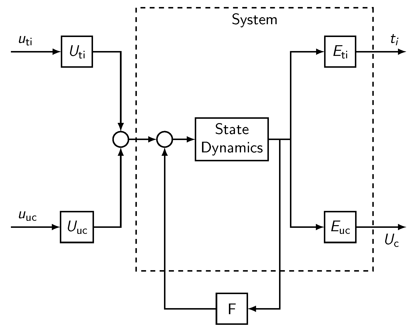
2. Dynamic Model
3. Reachable Internal Contact Forces
4. Noninteraction as a Structural Property
The Fundamental Theorem
- (a)
- the rigid–body object motions ,
- (b)
- the reachable internal forces ,
- (c)
- the mechanism redundancy .
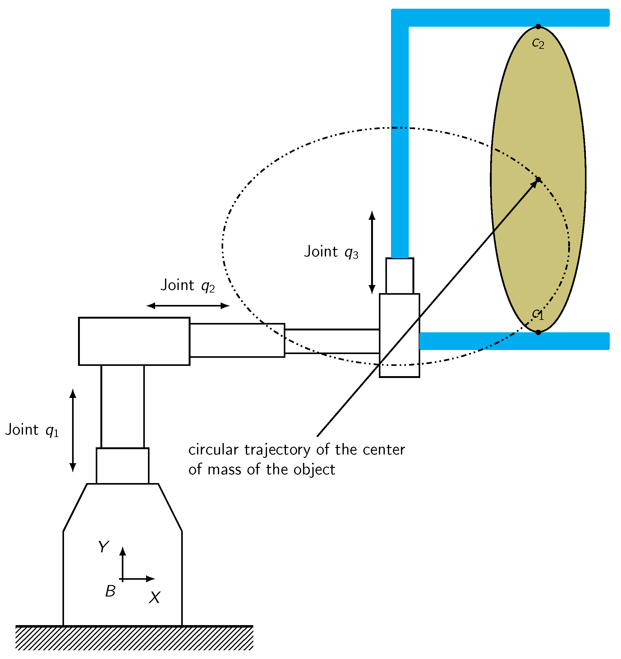
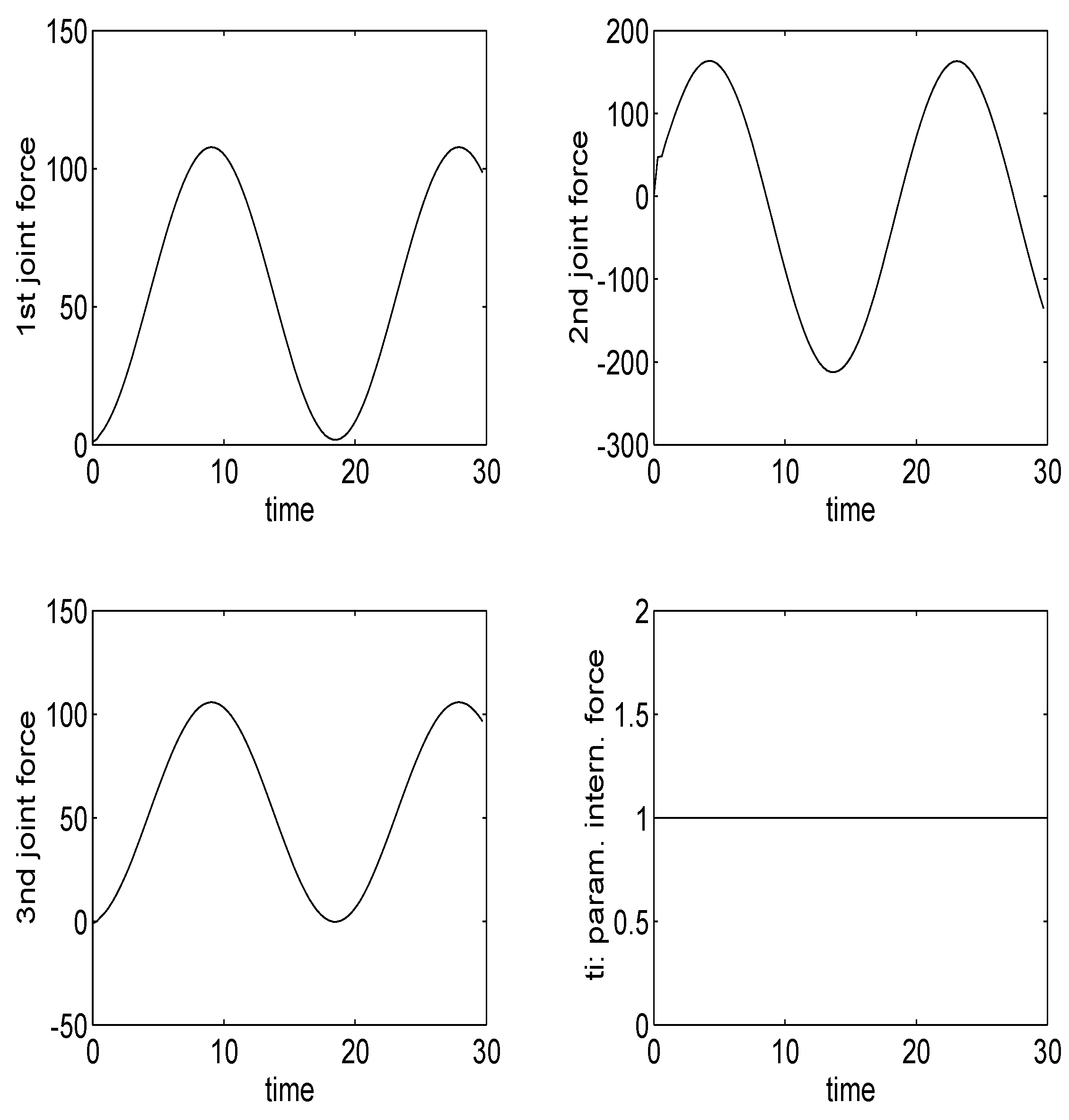
5. Case Study
General Procedure
- Item 1: Considering Equation (21), the reachable subspace of the internal contact force is calculated:
- Item 2: Once is obtained, partition using (23), is obtained as follows:
- Item 3: Considering Equation (21), matrix is calculated such that the following conditionis satisfied:
- Item 4: Considering Equation (22), the reachable subspace of the internal coordinated movements is calculated as follows:
- Item 5: Once is obtained, partition using (23), is obtained as follows:
- Item 6: Considering Equation (22), matrix is calculated such that the following conditionis satisfied:
- Item 7: The final state–feedback noninteracting matrix is the following:End
6. Conclusions and Future Work
Funding
Data Availability Statement
Conflicts of Interest
Nomenclature
| vector of manipulator joint positions | |
| vector of joint actuator torques | |
| vector locally describing the position and the orientation of a frame attached to the object | |
| vector of forces and torques resultant from external forces acting directly on the object | |
| force/torque interaction at the i-th contact | |
| lumped parameters of visco-elastic phenomena | |
| position of the armature | |
| vector describing the posture of the contact frame on the manipulator | |
| vector describing the posture of the contact frame on the object | |
| Jacobian matrix of the manipulator | |
| grasp matrix of the manipulator | |
| and | inertia symmetric and positive definite matrices |
| and | terms including the velocity-dependent and gravity forces of the manipulator and object, respectively |
| state space | |
| dynamic matrix | |
| input matrix | |
| disturbance matrix | |
| image of matrix (subspace spanned by the columns of matrix ) | |
| informative output | |
| output contact forces | |
| subspace of rigid body | |
| complementary subspace of rigid body | |
| minimum -invariant subspace containing (controllable subspace) | |
| maximum controlled invariant subspace contained in | |
| minimum conditioned invariant subspace containing | |
| subspace of reachable internal forces | |
| , and | rigid–body object motions, reachable internal forces and mechanism redundancy outputs |
| : -constrained controllability subspace | subspace of all the points reachable through trajectories leaving the origin and belonging to . |
| subspace of manipulator movements reachable from movement of the object | |
| subspace of object movements reachable from movement of the manipulator |
Appendix A
Appendix A.1. Demonstration of the Noninteraction Theorem
Appendix B
References
- Trinkle, J. On the stability and instantaneous velocity of grasped frictionless objects. IEEE Trans. Robot. Autom. 1992, 8, 477–880. [Google Scholar] [CrossRef]
- Bicchi, A.; Prattichizzo, D. Controllability of whole–Arm manipulation. In Proceedings of the 33rd CDC, Lake Buena Vista, FL, USA, 14–16 December 1994. [Google Scholar]
- Howard, W.S.; Kumar, V. Stability of planar grasps. In Proceedings of the 1994 IEEE International Conference on Robotics and Automation, San Diego, CA, USA, 8–13 May 1994. [Google Scholar]
- Seto, D.; Baillieul, J. Control problems in super-articulated mechanical systems. IEEE Trans. Autom. Control 1994, 39, 2442–2453. [Google Scholar] [CrossRef]
- Ismaeil, O.; Ellis, R. Grasping using the whole finger. In Proceedings of the 1994 IEEE International Conference on Robotics and Automation, San Diego, CA, USA, 8–13 May 1994. [Google Scholar]
- Melchiorri, C. Static force analysis for general cooperating manipulators. In Proceedings of the 1994 IEEE International Conference on Robotics and Automation, San Diego, CA, USA, 8–13 May 1994. [Google Scholar]
- Petreschi, P.; Prattichizzo, D.; Bicchi, A. Articulated structures with tendon actuation for whole-limb manipulation. In Proceedings of the 1994 IEEE International Conference on Robotics and Automation, San Diego, CA, USA, 8–13 May 1994. [Google Scholar]
- Bicchi, A.; Prattichizzo, D. A standard form for the dynamics of general manipulation systems. In Proceedings of the 1995 IEEE International Conference on Robotics and Automation, Nagoya, Japan, 21–27 May 1995. [Google Scholar]
- Bicchi, A.; Prattichizzo, D.; Sastry, S. Planning motions of rolling surfaces. In Proceedings of the 1995 34th IEEE Conference on Decision and Control, New Orleans, LA, USA, 13–15 December 1995. In Invited Session: Discontinuities Singularities and New Geometric Structures in Control Design of Nonlinear Systems. [Google Scholar]
- Le Tien, L.; Schaffer, A.A.; Hirzinger, G. MIMO State Feedback Controller for a Flexible Joint Robot with Strong Joint Coupling. In Proceedings of the 2007 IEEE International Conference on Robotics and Automation, Roma, Italy, 10–14 April 2007; pp. 3824–3830. [Google Scholar] [CrossRef]
- Albu-Schäffer, A.; Hirzinger, G. A globally stable state feedback controller for flexible joint robots. Adv. Robot. 2001, 15, 799–814. [Google Scholar] [CrossRef] [Green Version]
- Skogestad, S.; Postlethwaite, I. Multivariable Feedback Control, 2nd ed.; Wiley-Blackwell: Hoboken, NJ, USA, 2005. [Google Scholar]
- Hedman, M.; Mercorelli, P. FFTSMC with Optimal Reference Trajectory Generated by MPC in Robust Robotino Motion Planning with Saturating Inputs. In Proceedings of the 2021 American Control Conference (ACC), New Orleans, LA, USA, 25–28 May 2021; pp. 1470–1477. [Google Scholar] [CrossRef]
- Elsisi, M. Optimal design of nonlinear model predictive controller based on new modified multitracker optimization algorithm. Int. J. Intell. Syst. 2020, 35, 1857–1878. [Google Scholar] [CrossRef]
- Elsisi, M.; Ebrahim, M.A. Optimal design of low computational burden model predictive control based on SSDA towards autonomous vehicle under vision dynamics. Int. J. Intell. Syst. 2021, 36, 6968–6987. [Google Scholar] [CrossRef]
- Ali, M.N.; Soliman, M.; Mahmoud, K.; Guerrero, J.M.; Lehtonen, M.; Darwish, M.M.F. Resilient Design of Robust Multi-Objectives PID Controllers for Automatic Voltage Regulators: D-Decomposition Approach. IEEE Access 2021, 9, 106589–106605. [Google Scholar] [CrossRef]
- Ayman, M.; Soliman, M. Decentralised design of robust multi-objective PSSs: D-decomposition approach. IET Gener. Transm. Distrib. 2020, 14, 5392–5406. [Google Scholar] [CrossRef]
- Ayman, M.; Soliman, M. Robust multi-objective PSSs design via complex Kharitonov’s theorem. Eur. J. Control 2021, 58, 131–142. [Google Scholar] [CrossRef]
- Basile, G.; Marro, G. A state space approach to non-interacting controls. Ric. Autom. 1970, 1, 68–77. [Google Scholar]
- Basile, G.; Marro, G. Controlled and Conditioned Invariants in Linear System Theory; Prentice Hall: Hoboken, NJ, USA, 1992. [Google Scholar]
- Wonham, W.; Morse, A. Decoupling and pole assignment in linear multivariable systems: A geometric approach. SIAM J. Control 1970, 8, 1–18. [Google Scholar] [CrossRef]
- Morse, A.; Wonham, W. Decoupling and pole assignment by dynamic compensation. SIAM J. Control 1970, 8, 317–337. [Google Scholar] [CrossRef] [Green Version]
- Cutkosky, M.; Kao, I. Computing and controlling the compliance of a robotic hand. TransRA 1989, 5, 151–165. [Google Scholar] [CrossRef]
- Montana, D.J. The Kinematics of Contact Grasp. IJRR 1988, 7, 17–32. [Google Scholar] [CrossRef]
- Prattichizzo, D.; Bicchi, A. Consistent task specification for manipulation systems with general kinematics. ASME J. Dyn. Syst. Meas. Control 1997, 119, 760–767. [Google Scholar] [CrossRef] [Green Version]
- Murray, R.; Li, Z.; Sastry, S. A Mathematical Introduction to Robotic Manipulation; CRC: Boca Raton, FL, USA, 1994. [Google Scholar]
- Wonham, W. Linear Multivariable Control: A Geometric Approach; Springer: New York, NY, USA, 1979. [Google Scholar]
- Mercorelli, P.; Sergiyenko, O.; Hernandez-Balbuena, D.; Rodriguez-Quiñonez, J.; Flores-Fuentes, W.; Basaca-Preciado, L. Some Model Properties to Control a Permanent Magnet Machine Using a Controlled Invariant Subspace. IFAC-PapersOnLine 2015, 48, 366–371. [Google Scholar] [CrossRef]
- Mercorelli, P.; Haus, B.; Zattoni, E.; Aschemann, H.; Ferrara, A. Robust Current Decoupling in a Permanent Magnet Motor Combining a Geometric Method and SMC. In Proceedings of the 2018 IEEE Conference on Control Technology and Applications (CCTA), Copenhagen, Denmark, 21–24 August 2018; pp. 939–944. [Google Scholar] [CrossRef]
- Mercorelli, P. A Geometric Approach to the Decoupling Control and to Speed up the Dynamics of a General Rigid Body Manipulation System. In Applied Mechanics and Materials; Trans Tech Publications Ltd.: Baech, Switzerland, 2014; Volume 534, pp. 93–103. [Google Scholar] [CrossRef]
- Mercorelli, P.; Prattichizzo, D. A geometric procedure for robust decoupling control of contact forces in robotic manipulation. Kybernetika 2003, 39, 433–445. [Google Scholar]
- Mercorelli, P. Robust decoupling through algebraic output feedback in manipulation systems. Kybernetika 2010, 46, 850–869. [Google Scholar]
- Mercorelli, P. Geometric structures for the parameterization of non-interacting dynamics for multi-body mechanisms. Int. J. Pure Appl. Math. 2010, 59, 257–273. [Google Scholar]
- Mercorelli, P. A geometric algorithm for the output functional controllability in general manipulation systems and mechanisms. Kybernetika 2012, 48, 1266–1288. [Google Scholar]
- Prattichizzo, D.; Mercorelli, P. On some geometric control properties of active suspensions systems. Kybernetika 2000, 36, 549–570. [Google Scholar]
- Chu, D.; Mehrmann, V. Disturbance Decoupling for Descriptor Systems by State Feedback. SIAM J. Control Optim. 2000, 38, 1830–1858. [Google Scholar] [CrossRef]
- Chu, D.; Mehrmann, V. Disturbance decoupling for linear time-invariant systems: A matrix pencil approach. IEEE Trans. Autom. Control 2001, 46, 802–808. [Google Scholar] [CrossRef]
- Wang, Y.; Zhu, S.; Cheng, Z. A remark on “disturbance decoupling for linear time-invariant systems: A matrix pencil approach”. IEEE Trans. Autom. Control 2004, 49, 857–858. [Google Scholar] [CrossRef]
- Tosi, N.; David, O.; Bruyninckx, H. DOF Decoupling Task Graph Model: Reducing the Complexity of Touch-Based Active Sensing. Robotics 2015, 4, 141–168. [Google Scholar] [CrossRef] [Green Version]
- Wang, J.; Liang, F.; Zhou, H.; Yang, M.; Wang, Q. Analysis of Position, Pose and Force Decoupling Characteristics of a 4-UPS/1-RPS Parallel Grinding Robot. Symmetry 2022, 14, 825. [Google Scholar] [CrossRef]
- Lee, D.H.; Kim, Y.B.; Chakir, S.; Huynh, T.; Park, H.C. Noninteracting Control Design for 6-DoF Active Vibration Isolation Table with LMI Approach. Appl. Sci. 2021, 11, 7693. [Google Scholar] [CrossRef]
- Gierlak, P. Adaptive Position/Force Control of a Robotic Manipulator in Contact with a Flexible and Uncertain Environment. Robotics 2021, 10, 32. [Google Scholar] [CrossRef]
- Deng, Z.; Jonetzko, Y.; Zhang, L.; Zhang, J. Grasping Force Control of Multi-Fingered Robotic Hands through Tactile Sensing for Object Stabilization. Sensors 2020, 20, 1050. [Google Scholar] [CrossRef] [Green Version]
- Gal, I.-A.; Ciocirlan, A.-C.; Margaritescu, M. State Machine-Based Hybrid Position/Force Control Architecture for a Waste Management Mobile Robot with 5DOF Manipulator. Appl. Sci. 2021, 11, 4222. [Google Scholar] [CrossRef]
- Mercorelli, P. Invariant subspaces for grasping internal forces and non-interacting force-motion control in robotic manipulation. Kybernetika 2012, 48, 1229–1249. [Google Scholar]
- Salisbury, J.; Roth, B. Kinematic and force analysis of articulated mechanical hands. J. Mech. Trans. Autom. 1983, 105, 35–41. [Google Scholar] [CrossRef]
- Prattichizzo, D.; Bicchi, A. Dynamic analysis of mobility and graspability of general manipulation systems. IEEE Trans. Robot. Autom. 1998, 14, 241–258. [Google Scholar] [CrossRef]
- Bicchi, A.; Melchiorri, C.; Balluchi, D. On the mobility and manipulability of general multiple limb robots. IEEE Trans. Autom. Control 1995, 11, 215–228. [Google Scholar] [CrossRef]
- Prattichizzo, D.; Mercorelli, P.; Vicino, A. Noninteracting force/motion control in general manipulation systems. In Proceedings of the 35th IEEE Conference on Decision Control, CDC ’96, Kobe, Japan, 13 December 1996. [Google Scholar]


Publisher’s Note: MDPI stays neutral with regard to jurisdictional claims in published maps and institutional affiliations. |
© 2022 by the author. Licensee MDPI, Basel, Switzerland. This article is an open access article distributed under the terms and conditions of the Creative Commons Attribution (CC BY) license (https://creativecommons.org/licenses/by/4.0/).
Share and Cite
Mercorelli, P. A Theoretical Dynamical Noninteracting Model for General Manipulation Systems Using Axiomatic Geometric Structures. Axioms 2022, 11, 309. https://doi.org/10.3390/axioms11070309
Mercorelli P. A Theoretical Dynamical Noninteracting Model for General Manipulation Systems Using Axiomatic Geometric Structures. Axioms. 2022; 11(7):309. https://doi.org/10.3390/axioms11070309
Chicago/Turabian StyleMercorelli, Paolo. 2022. "A Theoretical Dynamical Noninteracting Model for General Manipulation Systems Using Axiomatic Geometric Structures" Axioms 11, no. 7: 309. https://doi.org/10.3390/axioms11070309