Article

Migration Law of the Roof of a Composited Backfilling Longwall Face in a Steeply Dipping Coal Seam

1
Key Laboratory of Western Mine Exploitation and Hazard Prevention, Ministry of Education, Xi’an University of Science and Technology, Xi’an 710054, China
2
School of Energy Engineering, Xi’an University of Science and Technology, Xi’an 710054, China
3
School of Mechanical Engineering, Liaoning Shihua University, Fushun 113001, China
4
Shaanxi Coal and Chemical Technology Institute Co., Ltd., Xi’an 710065, China
*
Author to whom correspondence should be addressed.
Minerals 2019, 9(3), 188; https://doi.org/10.3390/min9030188
Submission received: 12 February 2019 / Revised: 13 March 2019 / Accepted: 14 March 2019 / Published: 18 March 2019
(This article belongs to the Special Issue Backfilling Materials for Underground Mining)

Abstract

:
The artificial-caved rock composited backfilling approach can effectively restrain the dynamic phenomena in the coal seam and the associated roof and floor during mining operations, and can also improve the stability of the system of support and surrounding rock. In this study, based on the analysis of influencing factors affecting the surrounding rock movement and deformation of the composited backfilling longwall face in a steeply dipping coal seam, the roof mechanical model is developed, and the deflection differential equation is derived, to obtain the roof damage structure and the location of the roof fracture for the area without backfilling. The migration law of the roof under different inclination angles, mining depths, working face lengths, and backfilling ratios are analyzed. Finally, mine pressure is detected in the tested working face. Results show that the roof deflection, bending moment, and rotation drop with the increase of the inclination angle and backfilling ratio, whereas these parameters increase with greater mining depth and working face length. The roof failure location moves toward the upper area of the working face as the inclination angle and working face length increases, while it moves toward the center of the non-backfilling area with greater mining depth and backfilling ratio. Results from the proposed mechanical model agree well with the field test results, demonstrating the validity of the model, which can provide theoretical basis for a safe and efficient mining operation in steeply dipping coal seams.

1. Introduction

The backfilling technique can not only better control the overburden movement and surface subsidence with increased coal production, it can also reduce waste production and restrain the dynamic phenomena on coal seams and the associated roof and floor [1,2,3]. Although mining cost is increased when adopting the backfilling approach, it can effectively form a dynamic system that consists of a coal seam, support system, and backfilling material [4,5,6]. The filling body has enough strength to support the surrounding rock [7,8], which can enhance the strength and stability of the surrounding rock by transferring the stress state, from two-dimensions to three-dimensions [9,10,11]. The backfilling method is; therefore, gradually becoming one of the core technologies of green mining of coal resources in China, and it can be categorized into full backfilling and partial backfilling, according to the relative amount and area of backfilling [12,13,14].
Steeply dipping coal seams (SDCS) have been widely recognized to be difficult to mine [15]. However, this part of coal seams make up 20% of the proven reserves and 10% of the total coal production in China; 50% of SDCS are premium coking coal or anthracite coal, which are considered as rare coals and are being mined protectively [16,17]. Safe and efficient mining of SDCS is a major engineering problem in resource development in China, which is of great significance to the sustainable development of coal resources [18,19]. Since the SDCS can well meet the requirement for self-sliding of waste rock, and considering that the caved roof approaches the goaf bottom and the swelling of the loose rock [16,20,21], the composited backfilling approach, which combines both the artificial waste rock and caved roof waste, can be used in this case. The method can significantly reduce the backfilling costs, with a simpler filling system and less backfilling materials, while still enabling the backfilling approach when waste rock is not sufficient for some conditions. This approach can also better control the damage in surrounding rock, reduce the strata behavior, and improve the stability of support and surrounding rock, which can be considered as an effective approach to achieve safe and efficient mining of SDCS. The backfilling method of waste rock can be adopted by the long-distance backfilling technology with a scraper winch [22].
Many theoretical models have been proposed to study the mechanical behavior of the roof for horizontal or moderate inclined coal seams, these conceptual models include the stress arc, the hanging beam, the fractured beam, the hinged block, and the connecting beam [23,24,25]. However, a comprehensive understanding and theory on the mine pressure behavior for the SDCS with composited backfilling method is limited. Most previous studies focused on the backfilling mechanical model for the roof using a beam with fixed ends, based on the elastic beam or thin plate theory [26,27,28]. However, without the consideration of the lateral force on the roof for SDCS, these models fail to accurately describe the mechanical behavior of the roof in practice. Hence, this study establishes a mechanical model to account for the roof displacement and deformation in SDCS with the composited backfilling method. Lateral forces have been incorporated in the model to better study the displacement and deformation of the roof.

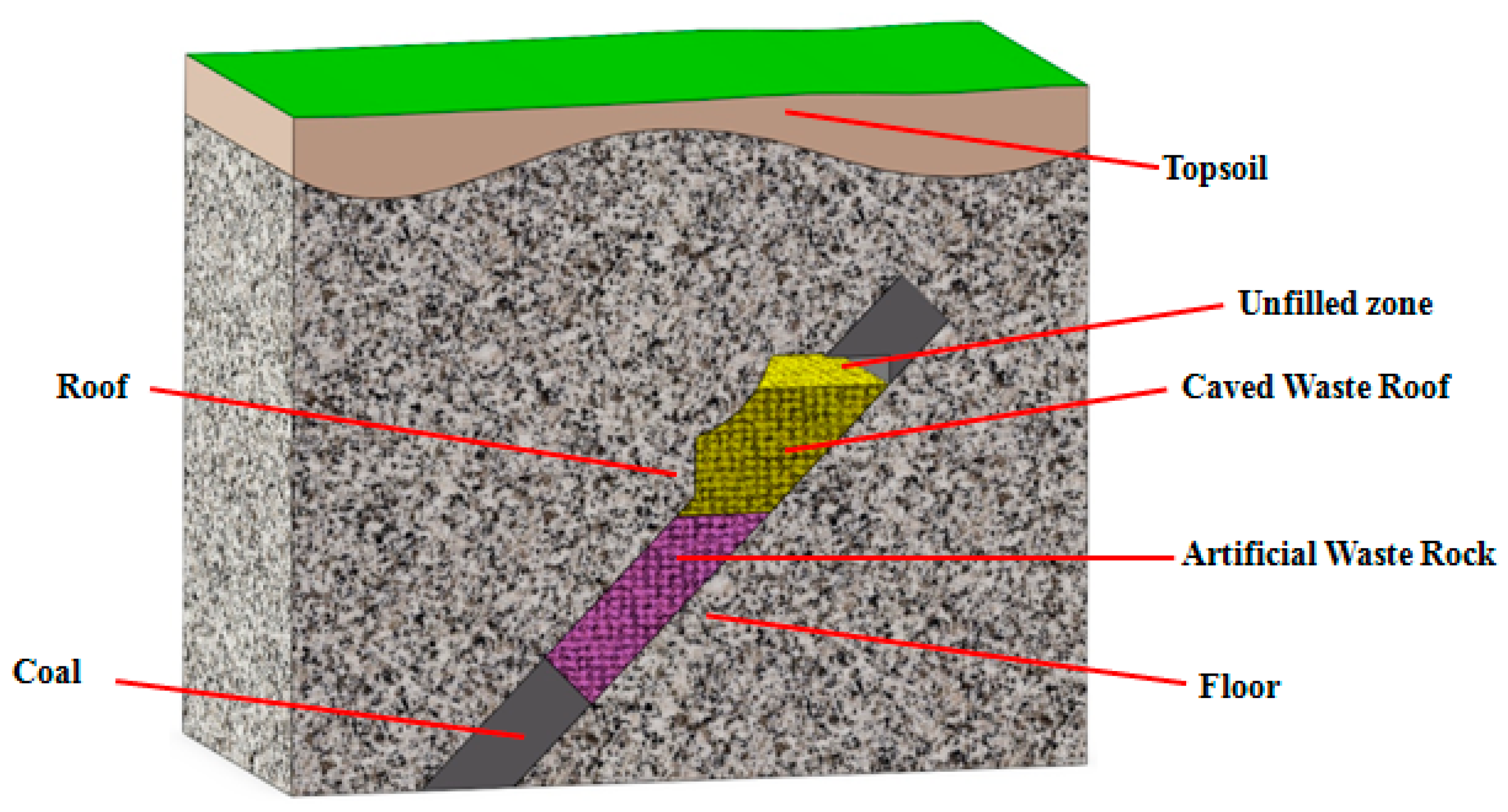
2. Influencing Factors Affecting the Surrounding Rock Displacement and Deformation

When the caving method is used to mine SDCS, the roof suffers a bending deformation toward the goaf and slides down along the bedding plane, as a result of gravity and stress from overlying strata [15,16]. As more coal is mined, the roof collapses and caved rocks roll toward the lower side of the goaf. As the working face advances, the above process keeps taking place until the goaf is filled up with waste rock. Based on the above analysis, the main reason for the roof movement is due to the space created during mining operations. When using the backfilling method, backfilling materials are injected to reduce the goaf space, which changes the movement of the roof and provides less space for roof bending deformation [29,30,31]. The stress in the surrounding rock is then insufficiently or partially released, which effectively reduces the extent and range of the roof failure. For backfilling mining, the coal seam inclination angle, mining depth, working face length, and backfilling ratio can affect the roof movement, a detailed analysis on each of these factors is given below.

2.1. Inclination Angle

When coal seams are mined, the roof is normally under bending deformation, with both the gravity and overburden stress. The roof collapses after the deformation reaches its critical value; therefore, the amount of force in the goaf direction is directly related to the extent of surrounding rock damage [32,33]. For SDCS, as the inclination angle increases, the force component of the roof and overburden gravity in the goaf direction is decreasing and the surrounding rock displacement and deformation become less [33,34]. Meanwhile, with higher inclination angle, the waste rocks tend to slide easier to the lower area when entering the goaf, leading to higher backfilling density and an improved control over the strata movement.

2.2. Mining Depth

With the increase of coal seam depth, the ground pressure increases progressively. In this case, greater energy is released to reach a new stress balance when the coal is mined, resulting in greater intensity for the overlying strata movement [15,16]. With the increase of mining depth, the geotechnical variables are subjected to various sources of uncertainties, which may lead to inaccurate prediction of the numerical results; the probabilistic back analysis method can be used in this case [35,36,37].

2.3. Backfilling Ratio

In backfilling mining, the movement and deformation of the surrounding rock are controlled within a reasonable range due to the joining of a filling body. With a higher backfilling ratio, the available space for strata movement becomes less, and hence less roof movement. Therefore, a high backfilling ratio can improve the control of surrounding rock movement. The backfilling ratio can be obtained by [26]:
k = a a + b
where k is the backfilling ratio; a is the length of backfilling area, m; and b is the length of the area without backfilling, m.

2.4. Working Face Length

The exposed area and period of the roof increases as the working face length increases, which leads to greater roof pressure and the higher potential for roof separation and failure [23]. Hence, the mine pressure occurrence is positively related to the working face length.

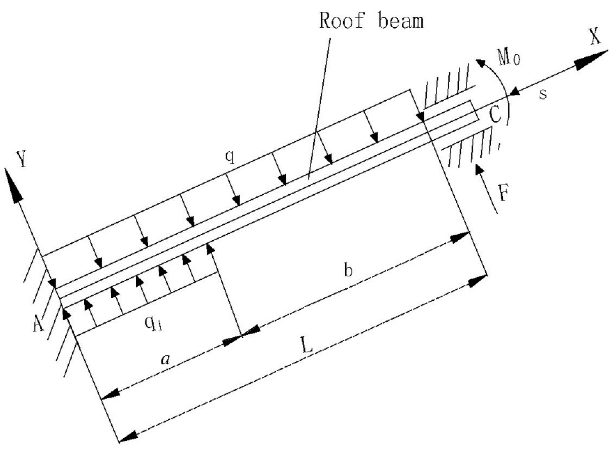
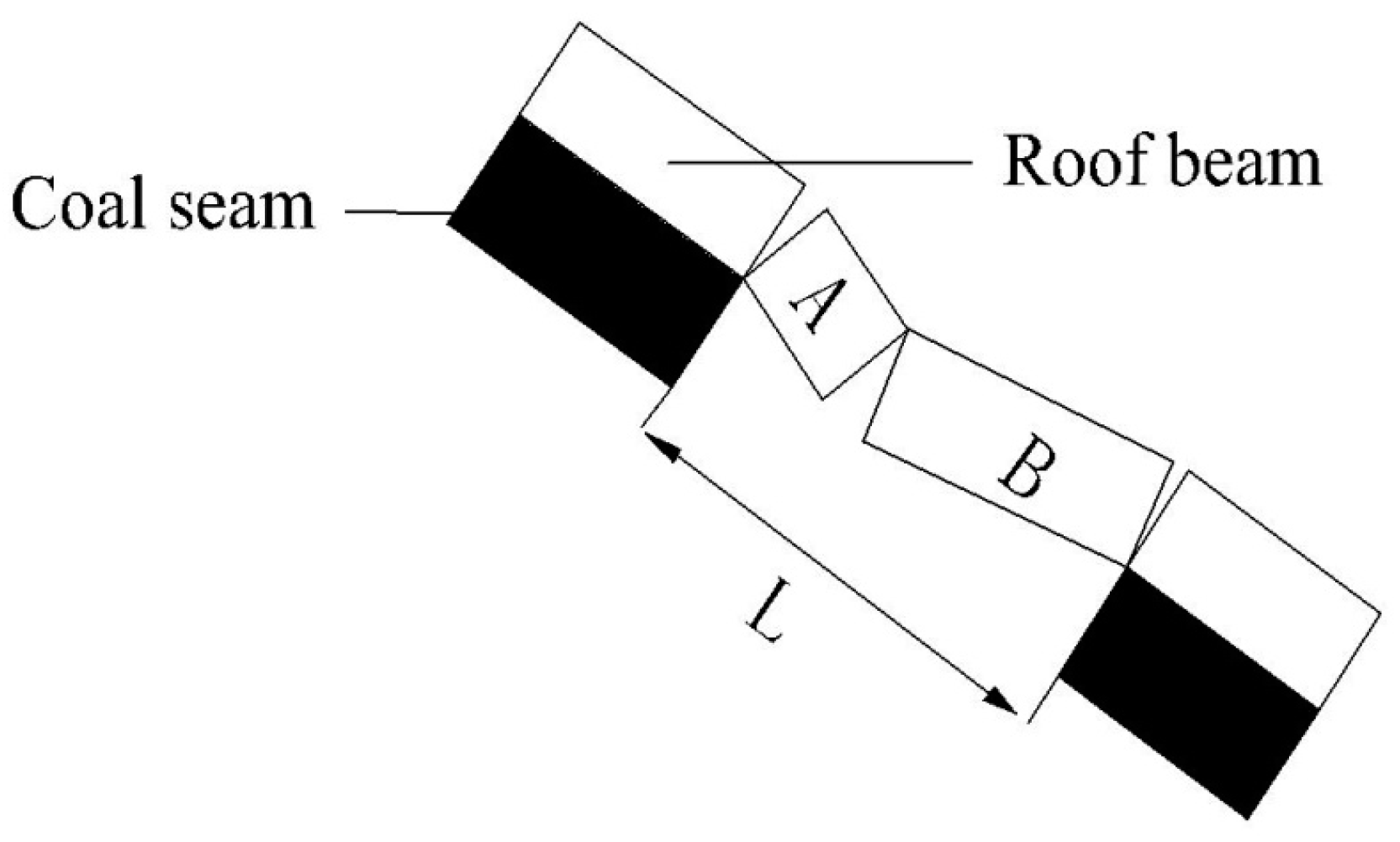
3. Mechanical Model of the Roof Beam

3.1. Establishment of Mechanical Model

During backfilling operations, the goaf space was filled up with filling materials, which changes the original shape of the goaf and reduces the hollow area, and; therefore, alters the displacement pattern, which results in a smaller roof deflection and a reduced roof damage range and level [38,39,40,41]. The composited backfilling longwall mining in SDCS is as demonstrated in Figure 1. Consider the complexity of the stress on the roof, a mechanical model, that accounts for the stress state of a roof beam per unit width along the inclination direction, is established, as shown in Figure 2. α is the inclination angle, a is the length of the backfilling area, b is the length of the area without backfilling, F, S, and M0 are the tangential force, normal force, and bending moment at C of the upper area of the working face, respectively, B is the juncture point of the with and without backfilling area, L is the length of the working face, H is the width of the roof, E is the elastic modulus, I is the moment of inertia, γ is the specific weight, and Ya is the depth of the coal seam. A is considered as the coordinate origin, X is for the inclination direction of the working face, and Y is in the direction perpendicular to the roof.
Since the coal seam depth is much greater than the working face length projected in the vertical direction, it is assumed that an evenly distributed load is applied to the overburden, with q = γYacosα. Stress even distribution is also assumed for the lower area of the working face using the waste rock, which has a corresponding load q1. The load for the upper area can be derived with S = γYasinαH.
Based on bending moment theory [23,25], the deflection differential equation of roof beam AB is given as:
y A B ( x ) = M 0 E I + F E I ( L x ) S E I y A B ( x ) q 2 E I ( L x ) 2 + q 1 ( a x ) 2 2 E I ;   0 x < a .
The deflection differential equation of roof beam BC is given as:
y B C ( x ) = M 0 E I + F E I ( L x ) S E I y B C ( x ) q 2 E I ( L x ) 2 ;   a x < L .
Consider the load characteristics and restraint conditions of roof beam AB and BC, the boundary conditions are:
y A B ( 0 ) = 0 θ A B ( 0 ) = 0 y A B ( a ) = y B C ( a ) y B C ( L ) = 0 θ B C ( L ) = 0 θ A B ( a ) = θ B C ( a ) .
The deflection equation of roof beam AB is given as:
y A B ( x ) = C 1 cos S E I x + C 2 sin S E I x + ( q 1 q 2 S ) x 2 + ( q L q 1 a F S ) x + ( M 0 S + F L S q L 2 2 S + q 1 a 2 2 S E I ( q 1 q ) S 2 ) .
The deflection equation of roof beam BC is given as:
y B C ( x ) = C 3 cos S E I x + C 4 sin S E I x q 2 S x 2 + ( q L F S ) x + ( M 0 S + F L S q L 2 2 S + E I q S 2 ) .
The rotation equation of roof beam AB is given as:
θ A B ( x ) = C 1 S E I sin S E I   x + C 2 S E I cos S E I   x + q 1 q S x + q L q 1 a F S .
The rotation equation of roof beam BC is given as:
θ B C ( x ) = C 3 S E I sin S E I   x + C 4 S E I cos S E I   x q S x + q L F S ,
where C1, C2, C3, C4, F, and M0 are constants, which are given by:
[ 1 0 0 0 1 S L S 0 S E I 0 0 0 1 S 0 0 cos S E I L sin S E I L 1 S 0 0 0 S E I sin S E I L S E I cos S E I L 0 1 S cos S E I a sin S E I a cos S E I a sin S E I a 0 0 sin S E I a cos S E I a sin S E I a cos S E I a 0 0 ] [ C 1 C 2 C 3 C 4 M 0 F ] = [ E I ( q 1 q ) S 2 + q L 2 2 S q 1 a 2 2 S q 1 a S q L S E I q S 2 E I q 1 S 2 0 ]
The bending moment equations of roof beam AB is given as:
M A B = E I ( C 1 S cos S E I x E I C 2 S sin S E I x E I + q 1 q S ) .
The bending moment equations of roof beam BC is given as:
M B C = E I ( C 3 S cos S E I x E I C 4 S sin S E I x E I q S ) ,
where α, L, H, a, b, Ya, E, I, and γ are constants, the maximum stress is at M’(x) = 0.
The maximum stress point of AB section is given by:
M A B = C 1 S S E I sin S E I x C 2 S S E I cos S E I   x = 0 x A B = E I S arctan C 2 C 1
The maximum stress point of BC section is given by:
M B C = C 3 S S E I sin S E I   x C 4 S S E I cos S E I   x = 0 x B C = E I S arctan C 4 C 3
Consider that the roof beam suffers failure in section BC with x = E I S arctan C 4 C 3 from the lower support point. The roof breaks and forms an asymmetric structure with two smaller beams, where one beam is B and the other one is A. As shown in Figure 3, the length of B is xB and the length of A is xA.

3.2. Roof Deformation Analysis

From the mechanical model of the roof, where α, L, H, a, b, Ya, E, I, and γ are constants, the inclination angel, mining depth, working face length and backfilling ratio are the main controlling factors for the backfilling performances. Parametric study on these four factors was conducted to improve the control of the stress distribution and the uneven damage caused by deformation in the surrounding rock. It can also improve the stability of the support and surrounding rock, increase working face length, generating more production and provide solution to the matching of backfilling capacity and working face production.
To better simulate the effect of each single factor on the migration law of the roof, the basic conditions are given in Table 1. Consider that the roof beam suffers failure in section BC, the analysis target is set as non-backfilling area. The deflection, bending moment, and rotation of the roof are calculated using Equations (6), (8), and (11), respectively.

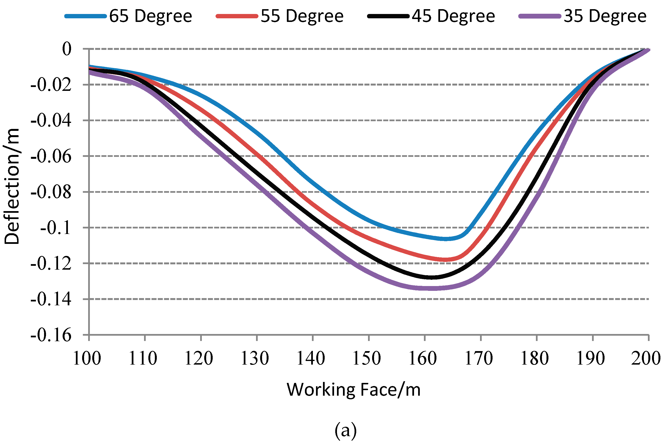
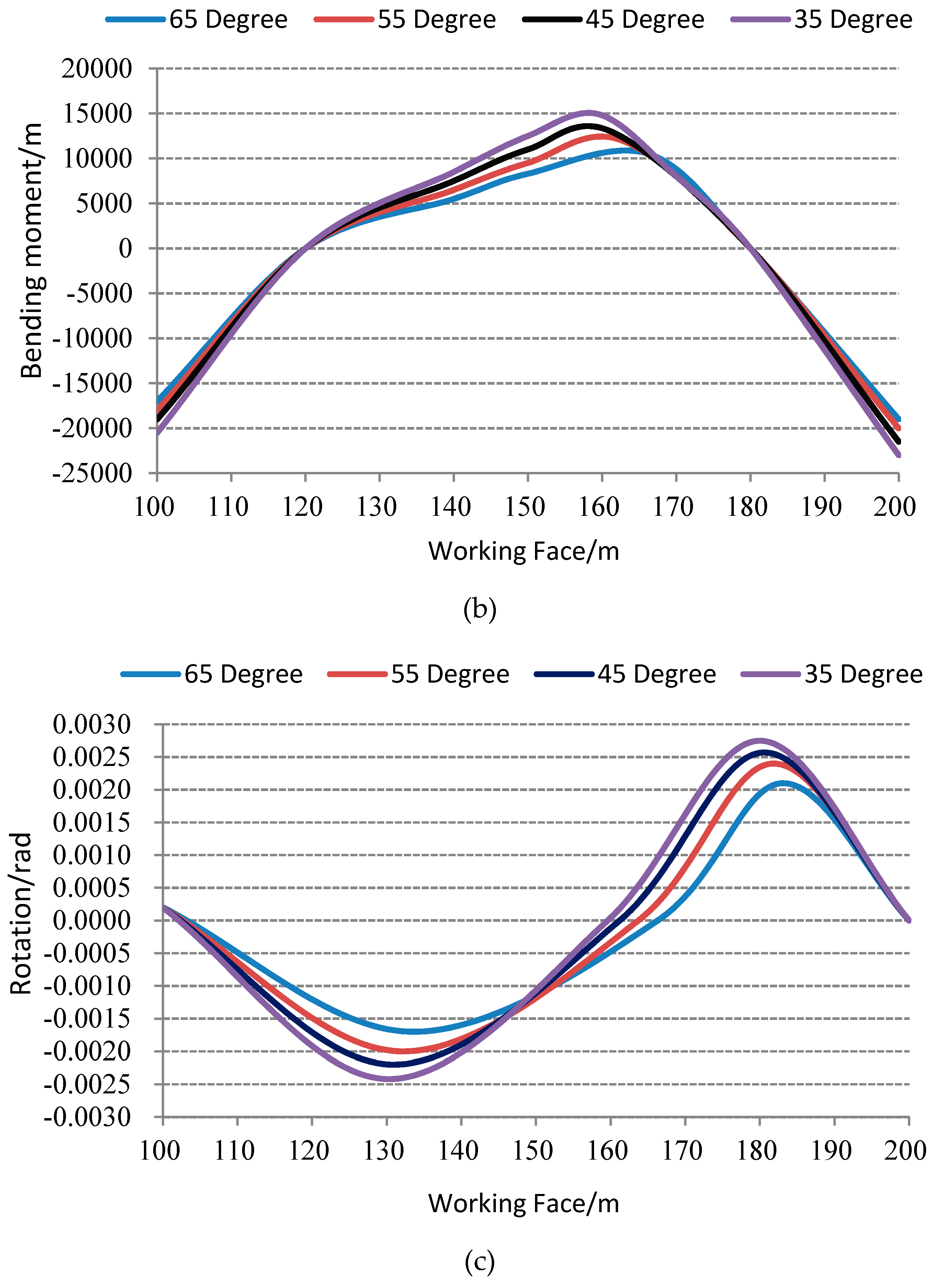
3.2.1. Roof Beam Deformation Behavior under Different Inclination Angles

Figure 4 shows the roof deflection, bending moment, and rotation for different working face locations with varying inclination angles (35°, 45°, 55°, and 65°). As shown in the Figure 4, with the backfilling materials, the largest roof deflection occurred in the middle area; the middle area also had the largest bending moment, followed by the lower area and the upper area; both ends of the roof and its middle area had relatively smaller rotation, whereas the lower and upper area had larger rotation. As the inclination angle increased, the tangential gravity component increased while the normal component decreased. The roof deflection, beading moment, and rotation also reduced as the inclination angle became greater. The roof failure point kept moving upward, resulting in an asymmetric failing behavior. The failure points were 159.6, 161.2, 163.7, and 166.3 m, respectively, the difference between each location increased progressively from 1.6 to 3.6 m; the difference was insignificant.

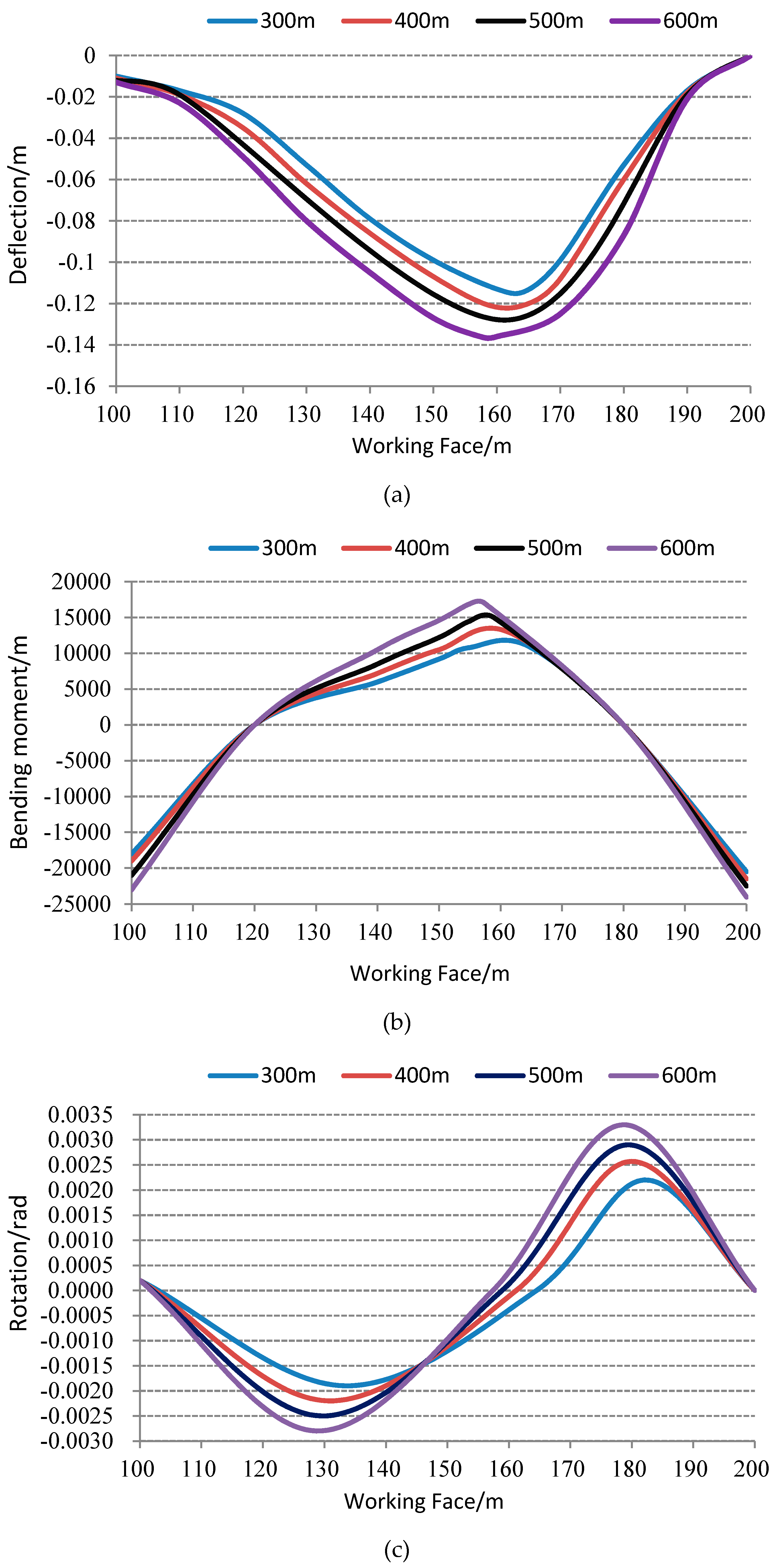
3.2.2. Roof Beam Deformation Behavior under Different Mining Depths

Figure 5 demonstrates the roof deflection, bending moment, and rotation for different working face locations with varying mining depths (300, 400, 500, and 600 m). From the Figure 5, it is shown that the roof beam had the largest deflection and bending moment in the middle area, followed by the lower area and the upper area; both ends of the roof and its middle area had relatively smaller rotation, whereas the lower and upper area had larger rotation. With greater mining depth, the ground pressure became higher and the roof and floor experienced more damage from mining disturbances, the damaged zone expanded to the surrounding rock, and the roof deflection, bending moment, and rotation all increased accordingly. The failure points were 164.5, 161.2, 158.9, and 157.4 m, respectively, failing behavior became less asymmetric and the failure location approached the middle area of the non-backfilling area, the difference between each location decreased gradually from 3.3 to 1.5 m; the difference was insignificant.

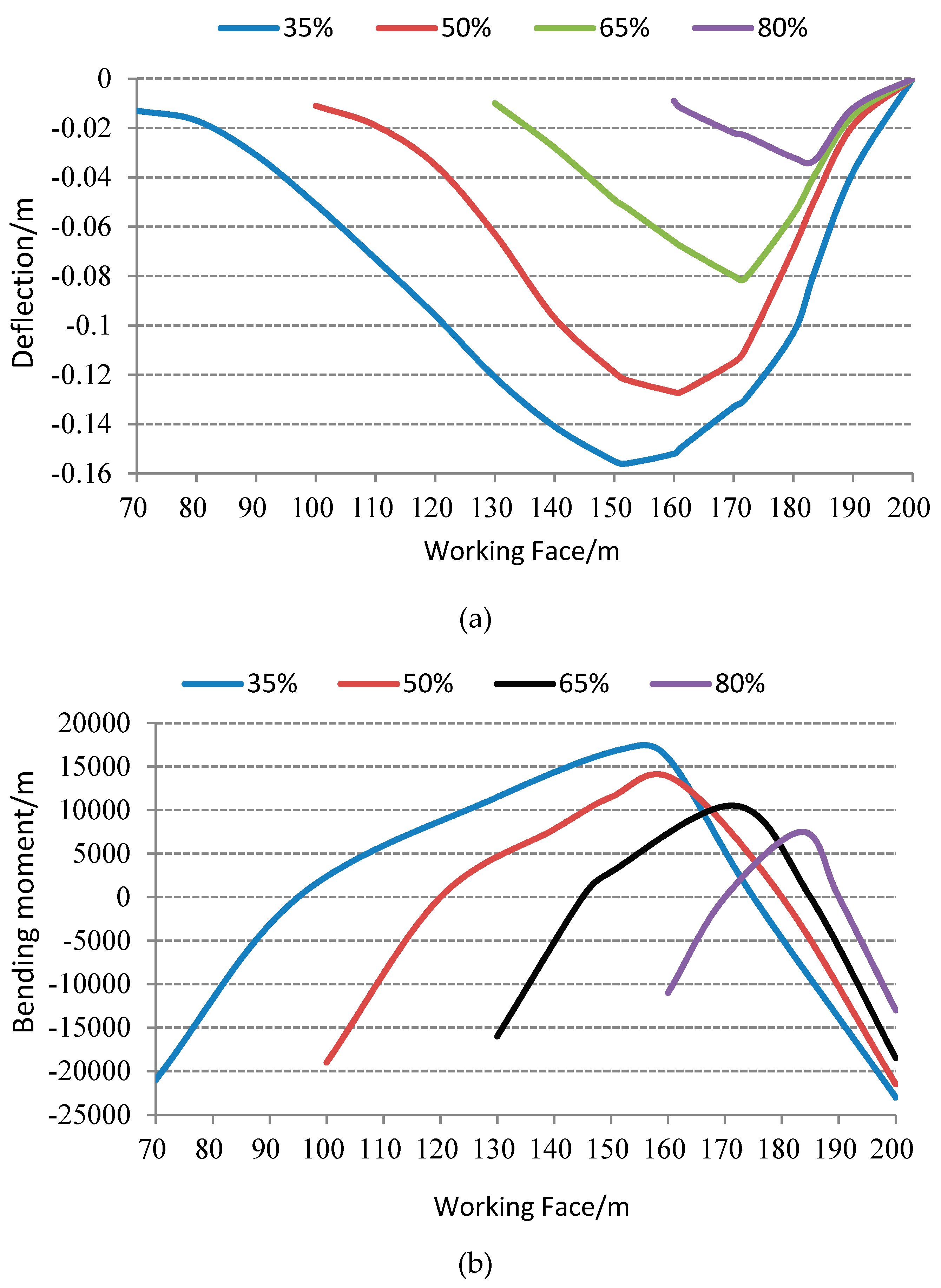
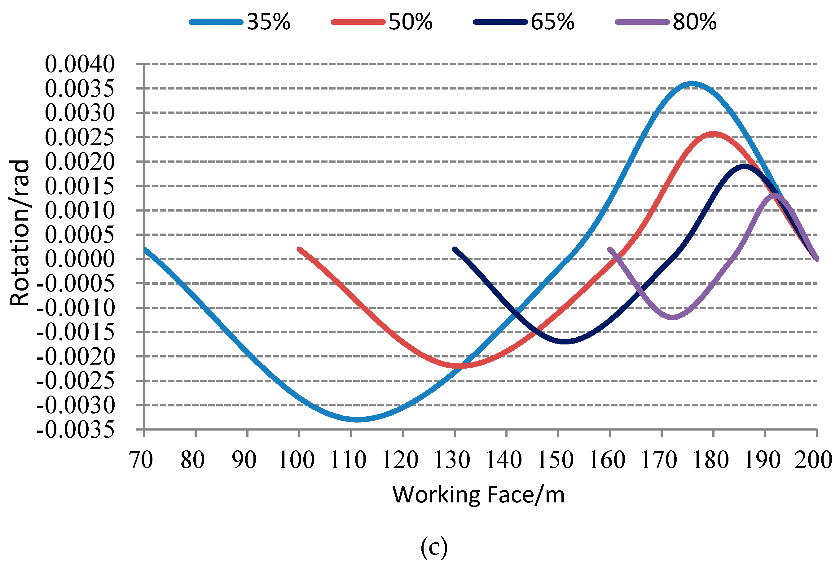
3.2.3. Roof Beam Deformation Behavior under Different Backfilling Ratios

Figure 6 displays the roof deflection, bending moment, and rotation for different working face locations with varying backfilling ratios (35%, 50%, 65%, and 80%). From the Figure 6, it is demonstrated that the roof beam had the largest bending moment and deflection in the middle area, followed by the lower area and the upper area; both ends of the roof and its middle area had relatively smaller rotation, whereas the lower and upper area had larger rotation. With higher backfilling ratio, more backfilling materials produced supporting effect along with the roof and floor. The stress from the surrounding rock was transferred to the backfilling materials, which formed a stress recovery zone in the roof and floor, which resulted in reduced roof deflection, bending moment, and rotation. The failure points were 151.9, 161.2, 171.9, and 183.6 m, respectively, the difference between each location increased from 9.3 to 11.7 m. The failure location approached the middle area of the non-backfilling area in a less symmetric manner, with the distance to the non-backfill center of 16.9, 11.2, 6.2, and 3.6 m, respectively.

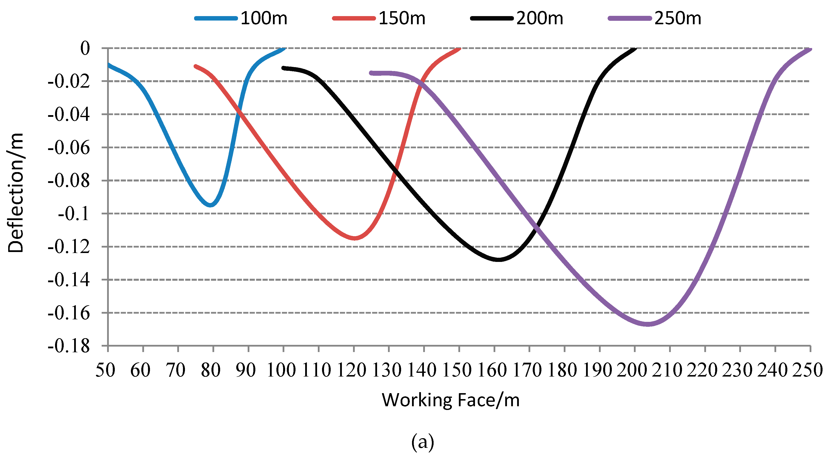
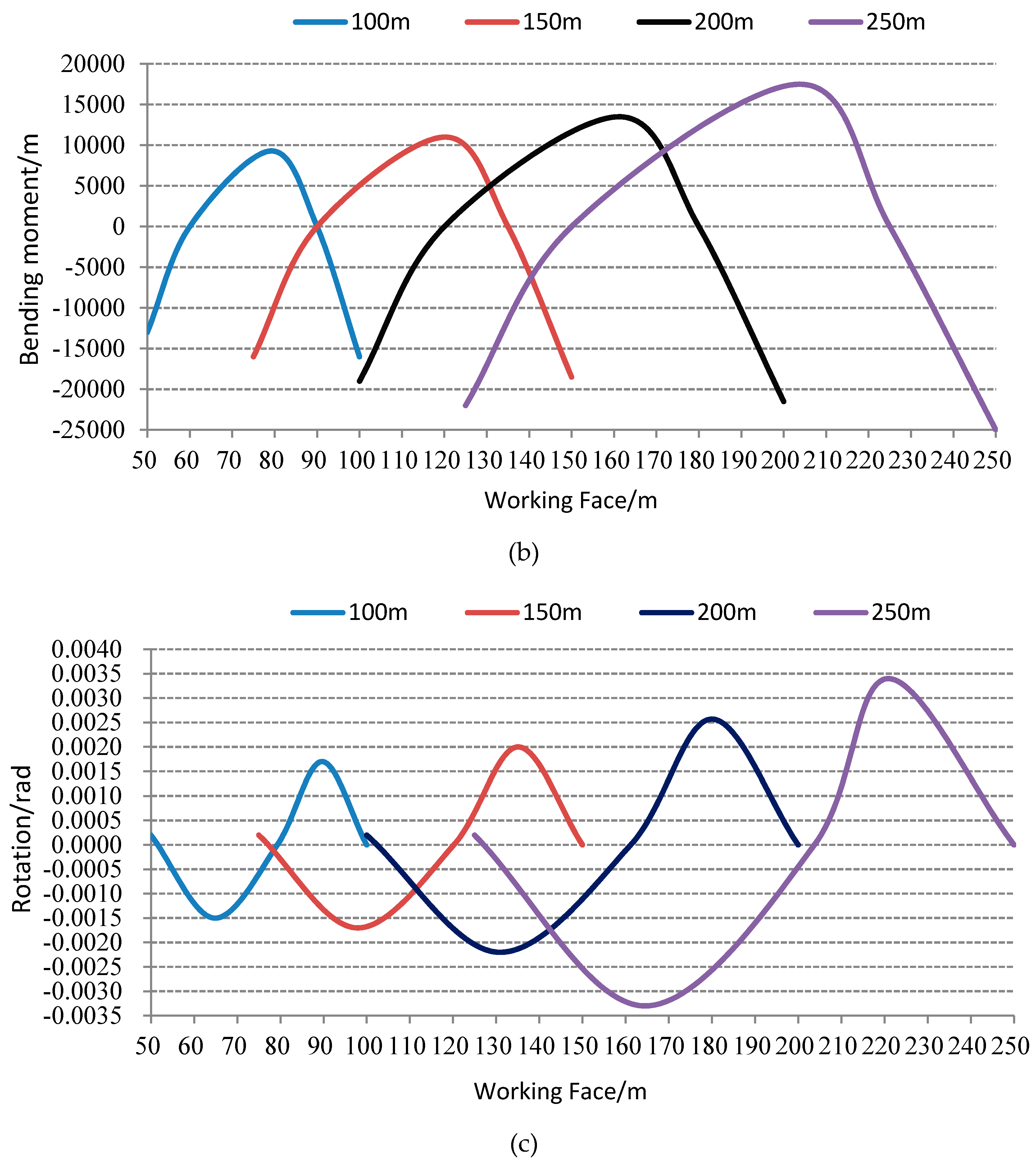
3.2.4. Roof Beam Deformation Behavior under Different Working Face Lengths

Figure 7 shows the roof deflection, bending moment, and rotation for different working face locations with varying working face lengths (100, 150, 200, and 250 m). As shown in the Figure 7, with the backfilling materials, the largest roof deflection occurred in the middle area; the middle area also had the largest bending moment, followed by the lower area and the upper area; both ends of the roof and its middle area had relatively smaller rotation, whereas the lower and upper area had larger rotation. As the working face length increased, the roof deflection, bending moment, and rotation all increased accordingly. The failure points were 79.3, 120.2, 161.2, and 203.75 m, respectively, the difference between each location increased from 40.9 to 42.55 m. The roof failure point kept moving upward, resulting in an asymmetric failing behavior, with the distance to the non-backfilling center of 4.3, 7.7, 11.2, and 16.25 m, respectively.

4. Field Test

4.1. Working Face Condition

The basic roof of the experimental 1125 working face of Yaojie Colliery is 14.9 m high and consists of mixed color of sandstone and conglomerate; the immediate roof is 3.51 m and made of black mudstone and sandstone; the height of the false roof ranges from 0 to 1.21 m and is mostly black mudstone. The length of the work face is 70.9 m with an inclination angle α = 32°, the evenly distributed load on overburden equals γh, the backfilling ratio is 10%, γ is the mean specific weight of the overburden which equals 27 kN·m−3, the working face burying depth is around 400 m, and the width of support is 1.5 m.
The breaking location of the roof was calculated by Equations (9) and (13), which was at x = 46.05 m. This means that the roof would break at 46.05 m away from the lower area of the working face, which corresponds to support area 31#. As the working face advances, supports in this area receive high loads from the roof deformation. Therefore, it is necessary to reinforce the supports in this area to prevent chain type catastrophe from support sliding and other potential accidents.

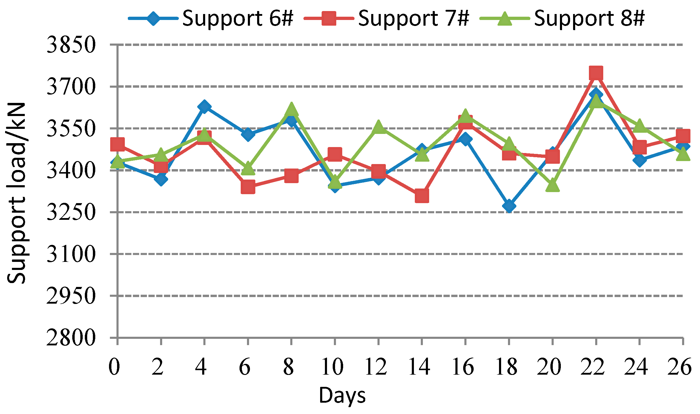
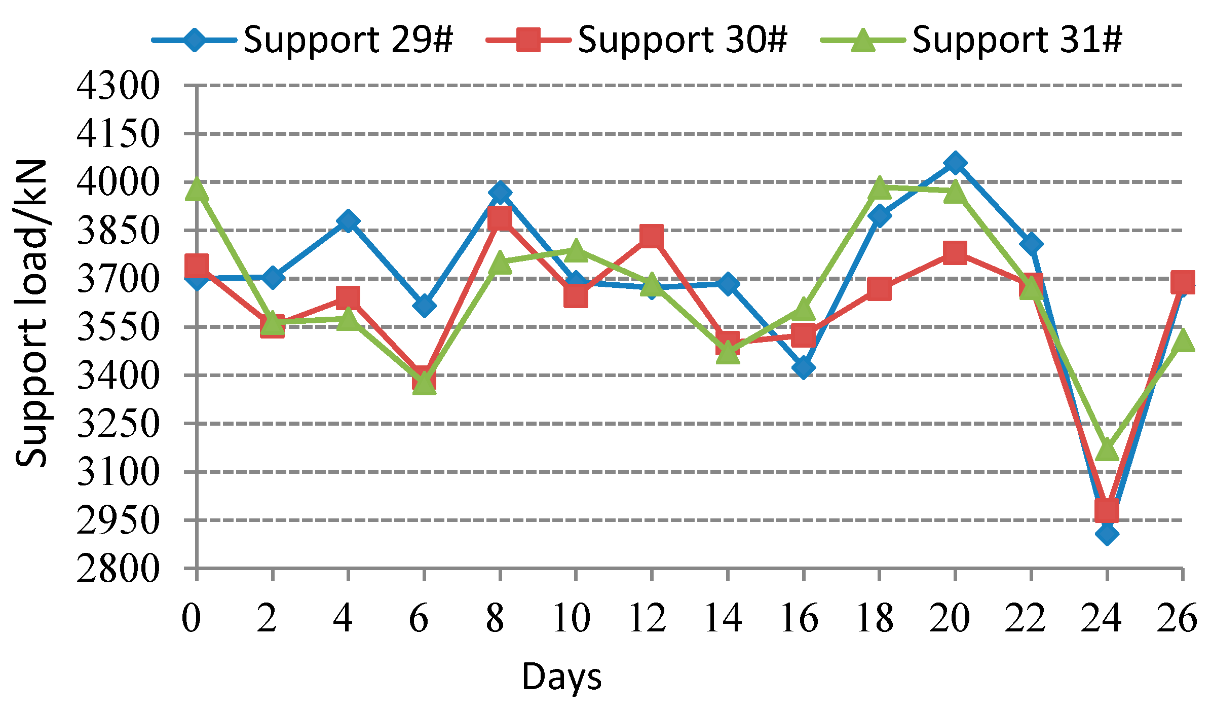
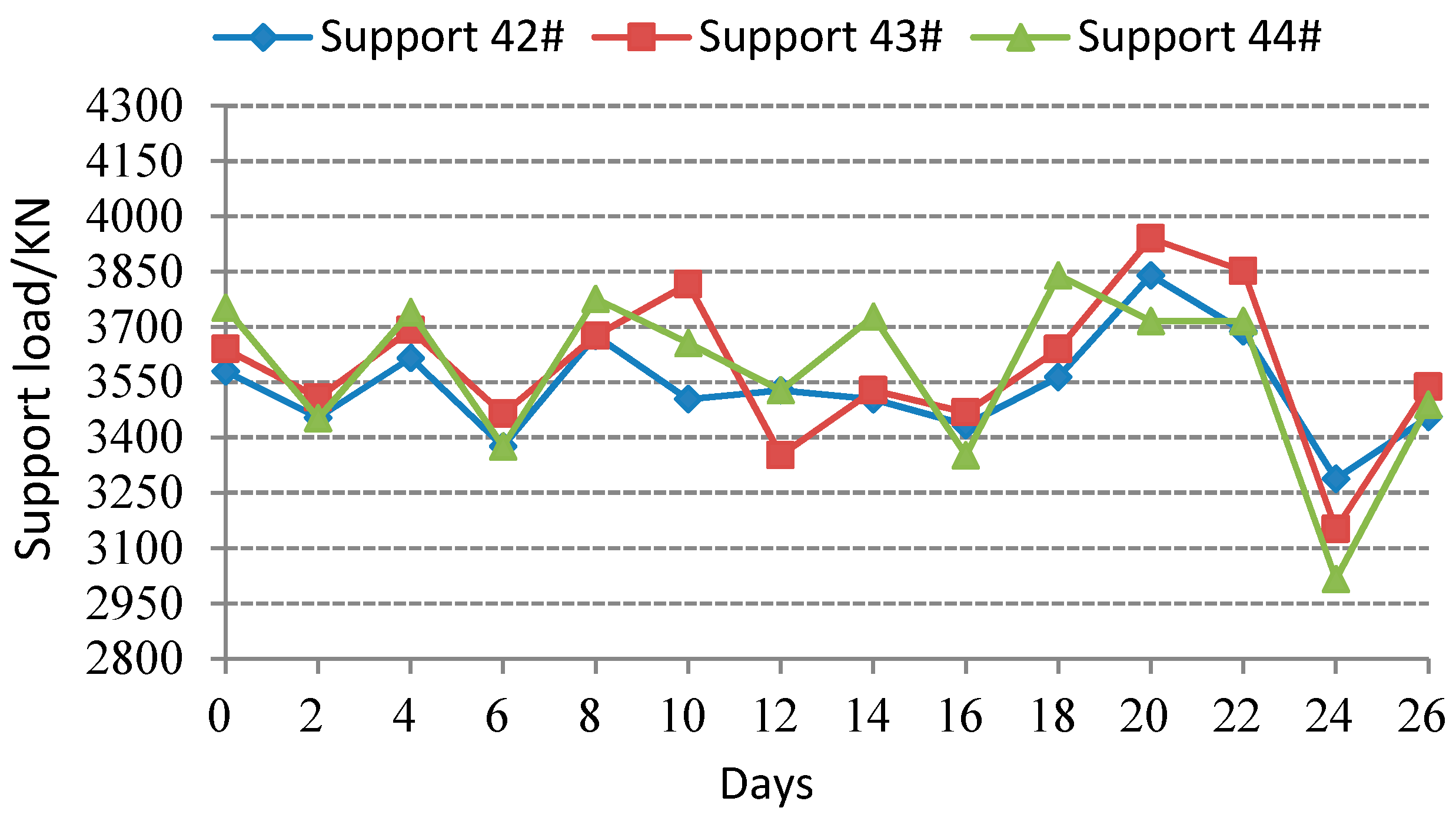
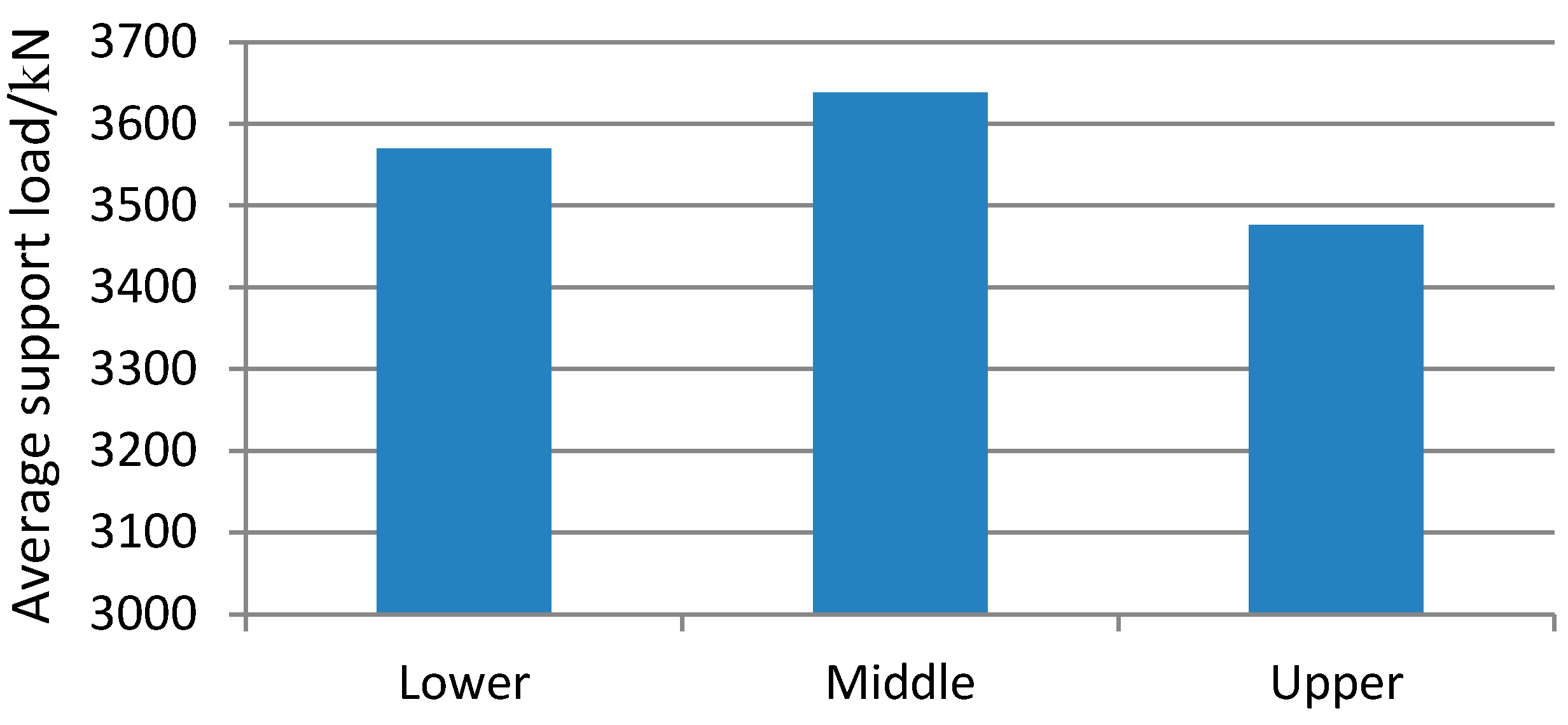
4.2. Mine Pressure Observations

To understand the mine pressure in the tested working face, to improve the management of the support system, mine pressure of the working face was measured in three areas along the inclination direction including the lower area (support 6#, 7#, and 8#), middle area (support 29#, 30#, and 31#) and upper area (support 42#, 43#, and 44#). Each of these supports was installed with stress sensors to measure the work resistance of the support, and results were collected and transferred to the computer of KJ24 dynamic mine pressure detection system.
The load on the supports of the upper, middle, and lower area are plotted in Figure 8, Figure 9, Figure 10 and Figure 11.
From Figure 8, Figure 9, Figure 10 and Figure 11, the following conclusion were drawn:
(1) The load on the working face supports has obviously inclined subarea characteristics, the supports in the lower area have an average load of 3476 kN, the load is quite evenly distributed with litter variance. The supports in the middle area have the greatest average load of 3638 kN, the load is unevenly distributed with large variance. The supports in the upper area have an average load of 3569 kN, the load is also unevenly distributed with large variance. This observation agrees with the common load behavior of SDCS, the proposed mechanical model, and the roof deformation analysis.
(2) The load on supports has significantly increased on the 20th day in the middle and upper areas, indicating that the roof has broken in these areas, which leads to a sudden increase of load and weighting of the roof. The load on supports increases dramatically during weighting, which causes the support to fall and; therefore, they are not able to effectively transfer the stress from the roof. The load on supports decreases rapidly on the 24th day, indicating that the supports have fallen and are not able to sufficiently support the roof, which has damaged the integrity of the R system of the “R(Roof)-S(Support)-F(Floor)” system [15].
(3) The weighting in different zones along the inclination direction follow a certain sequence, in which the weighting takes place in the middle area first, then the upper area, and finally the lower area. The load on supports of the middle and upper areas has increased sharply during weighting, indicating a dynamic strata movement and a higher potential of the support falling. The weighting occurs in the lower area gradually, about two days later than the other two areas.

5. Conclusions

(1) A mechanical model with lateral forces to account for the roof displacement and deformation in SDCS with composited backfilling method is established. The roof beam firstly breaks at x = E I S arctan C 4 C 3 , and forms an asymmetric three-hinged arch structure with two smaller beams. The upper beam is located at the rock dynamic movement area in the upper area of the working face; the lower backfilling area is the static area and the middle area is the transition area.
(2) The main factors that contribute to the composited backfilling method in SDCS were identified, which include the inclination angle, mining depth, working face length, and backfilling ratio; it is demonstrated that the largest roof deflection occurs in the middle area; the middle area also has the largest bending moment, followed by the lower area and the upper area; both ends of the roof and its middle area have relatively smaller rotation where the lower and upper area have larger rotation; the roof deflection, bending moment and rotation all decrease with the increase of inclination angle and backfilling ratio, while they increase with greater mining depth and working face length; for fixed backfilling ratio, the roof failure location moves upwards with greater inclination angle and working face length and moves toward middle area with greater mining depth; the roof failure location moves toward the non-backfilling center with higher backfilling ratio with significant differences.
(3) The roof will break at 46.05 m away from the lower area of the tested working face using the model calculation, which corresponds to support area 31#. According to the mine pressure observation, the middle area has the greatest load while the upper area has less load and the lower area has the least amount of load. This observation agrees well with the proposed mechanical model, demonstrating the validity of the model, which can provide a solid theoretical basis for further study on the application of composited backfilling in SDCS.
Based on the work presented in this paper, the focus of future studies should be on further validation of the established mechanical and mathematical model; therefore, field stress distribution in space and time domain will be monitored as the mining and backfilling work face advance.

Author Contributions

W.Y. developed the idea and edited the paper; Y.P. provided theoretical direction; L.M. designed and analyzed the mechanical model; and J.H. carried out the data analysis.

Funding

This study was financially supported by the National Natural Science Foundation of China (Nos. 51604212, 51604213, 51634007).

Acknowledgments

The authors would like to extend their sincere appreciation to the Yaojie Coal and Electricity Group Co., Ltd. for field test and data collection.

Conflicts of Interest

The authors declare no conflicts of interest.

References

  1. Zhang, J.X.; Li, B.Y.; Zhou, N.; Zhang, Q. Application of solid backfilling to reduce hard-roof caving and longwall coal face burst potential. Int. J. Rock Mech. Min. 2016, 88, 197–205. [Google Scholar] [CrossRef]
  2. Zhang, Q.; Zhang, J.X.; Huang, Y.L.; Ju, F. Backfilling technology and strata behaviors in fully mechanized coal mining working face. Int. J. Min. Sci. Technol. 2012, 22, 151–157. [Google Scholar] [CrossRef]
  3. Yilmaz, E.; Belem, T.; Benzaazoua, M. Effects of curing and stress conditions on hydromechanical, geotechnical and geochemical properties of cemented paste backfill. Eng. Geol. 2014, 168, 23–37. [Google Scholar] [CrossRef]
  4. Zhang, J.X.; Li, M.; Taheri, A.; Zhang, W.Q.; Wu, Z.Y.; Song, W.J. Properties and Application of Backfill Materials in Coal Mines in China. Minerals 2019, 9, 53. [Google Scholar] [CrossRef]
  5. Huang, Y.L.; Zhang, J.X.; An, B.F.; Zhang, Q. Overlying strata movement law in fully mechanized coal mining and backfilling longwall face by similar physical simulation. J. Min. Sci. 2011, 47, 618–627. [Google Scholar]
  6. Belem, T.; Benzaazoua, M.; Bussière, B. Mechanical behaviour of cemented paste backfill. In Proceedings of the 53rd Candadian Geotechnical Conference, Montreal, QC, Canada, 15–18 October 2000; pp. 373–380. [Google Scholar]
  7. Zhang, J.; Deng, H.W.; Taheri, A.; Deng, J.R.; Ke, B. Effects of Superplasticizer on the Hydration, Consistency, and Strength Development of Cemented Paste Backfill. Minerals 2018, 8, 381. [Google Scholar] [CrossRef]
  8. Zhao, Y.; Soltani, A.; Taheri, A.; Karakus, M.; Deng, A. Application of Slag–Cement and Fly Ash for Strength Development in Cemented Paste Backfills. Minerals 2019, 9, 22. [Google Scholar] [CrossRef]
  9. Hao, J.; Shi, Y.K.; Lin, J.X.; Wang, X.; Xia, H.C. The Effects of Backfill Mining on Strata Movement Rule and Water Inrush: A Case Study. Processes 2019, 7, 66. [Google Scholar] [CrossRef]
  10. Seryakov, V.M. Mathematical modeling of stress-strain state in rock mass during mining with backfill. J. Min. Sci. 2014, 50, 847–854. [Google Scholar] [CrossRef]
  11. Zhang, J.X.; Miao, X.X.; Guo, G.L. Development status of backfilling technology using raw waste in coal mining. J. Min. Saf. Eng. 2009, 26, 395–401. [Google Scholar]
  12. Guo, G.L.; Zhu, X.J.; Zha, J.F.; Wang, Q. Subsidence prediction method based on equivalent mining height theory for solid backfilling mining. Trans. Nonferrous Met. Soc. China 2014, 24, 3302–3308. [Google Scholar] [CrossRef]
  13. Miao, X.X.; Huang, Y.L.; Ju, F.; Mao, X.B.; Guo, G.L.; Zhang, J.X. Strata movement theory of dense backfill mining. J. China Univ. Min. Technol. 2012, 41, 863–867. [Google Scholar]
  14. Al Heib, M.M.; Didier, C.; Masrouri, F. Improving short- and long-term stability of underground gypsum mine using partial and total backfill. Rock Mech. Rock Eng. 2010, 43, 447–461. [Google Scholar] [CrossRef]
  15. Wu, Y.P.; Liu, K.Z.; Yun, D.F.; Xie, P.S.; Wang, H.W. Research progress on the safe and efficient mining technology of steeply dipping seam. J. China Coal. Soc. 2014, 39, 1611–1618. [Google Scholar]
  16. Xie, P.S. Response of Overburden Structure and Its Stability around the Longwall Mining Face Area in Steeply Dipping Seam. Ph.D. Thesis, Xi’an University of Science and Technology, Xi’an, China, 2011. [Google Scholar]
  17. Ma, F.H.; Sun, L.; Li, D. Numerical simulation analysis of covering rock strata as mining steep-inclined coal seam under fault movement. Trans. Nonferrous. Metals. Soc. China 2011, 21, 556–561. [Google Scholar] [CrossRef]
  18. Zhang, Y.Q.; Tang, J.X.; Xiao, D.Q. Spontaneous caving and gob-side entry retention of thin seam with large inclined angle. Int. J. Min. Sci. Technol. 2014, 24, 441–445. [Google Scholar] [CrossRef]
  19. Wang, J.A.; Jiao, J.L. Criteria of support stability in mining of steeply inclined thick coal seam. Int. J. Rock Mech. Min. Sci. 2016, 82, 22–35. [Google Scholar] [CrossRef]
  20. Yin, Y.C.; Zou, J.C.; Zhang, Y.B.; Qiu, Y.; Fang, K.; Huang, D.M. Experimental study of the movement of backfilling gangues for goaf in steeply inclined coal seams. Arab. J. Geosci. 2018, 11, 318. [Google Scholar] [CrossRef]
  21. Taheri, A.; Lee, Y.; Medina, M.A.G. A modified coal mine roof rating classification system to design support requirements in coal mines. J. Inst. Eng. 2017, 98, 1–10. [Google Scholar] [CrossRef]
  22. Yin, Y.C.; Zhao, T.B.; Zhang, Y.B.; Tan, Y.L.; Qiu, Y.; Taheri, A.; Jing, Y. An Innovative Method for Placement of Gangue Backfilling Material in Steep Underground Coal Mines. Minerals 2019, 9, 107. [Google Scholar] [CrossRef]
  23. Qian, M.G. Mining Pressure and Strata Control; China University of Mining and Technology Press: Xuzhou, China, 2003. [Google Scholar]
  24. Zhang, Y.D.; Cheng, J.Y.; Wang, X.X.; Feng, Z.J.; Ji, M. Thin plate model analysis on roof break of up-dip or down-dip mining stope. J. Min. Saf. Eng. 2010, 27, 487–493. [Google Scholar]
  25. Qian, M.G.; Miao, X.X.; Xu, J.L. The Theory of Key Strata in Ground Control; China University of Mining and Technology Press: Xuzhou, China, 2003. [Google Scholar]
  26. Yao, Q.; Feng, T.; Liao, Z. Damage characteristics and movement of inclined strata with sublevel filling along the strike in the steep seam. J. China Coal. Soc. 2017, 42, 3096–3105. [Google Scholar]
  27. Huang, Q.X.; Lai, J.Q. Study on mechanical model of aquifuge beam supported by filling strip in the water preserved mining. J. Min. Saf. Eng. 2016, 33, 592–596. [Google Scholar]
  28. Deng, X. Strata behavior in extra-thick coal seam mining with upward slicing backfilling technology. Int. J. Min. Sci. Technol. 2016, 26, 587–592. [Google Scholar] [CrossRef]
  29. Wu, D.; Cai, S.J.; Liu, Y.C. Effects of binder on suction in cemented gangue backfill. Mag. Concr. Res. 2016, 68, 593–603. [Google Scholar] [CrossRef]
  30. Ercikdi, B.; Külekci, G.; Yılmaz, T. Utilization of granulated marble wastes and waste bricks as mineral admixture in cemented paste backfill of sulphide-rich tailings. Constr. Build. Mater. 2015, 93, 573–583. [Google Scholar] [CrossRef]
  31. Chen, J.; Du, J.P.; Zhang, W.S.; Zhang, J.X. An elastic model of overlying strata movement during coal mining with gangue back-filling. J. China Univ. Min. Technol. 2012, 41, 14–19. [Google Scholar]
  32. Yun, D.F.; Liu, Z.; Cheng, W.D.; Fan, Z.D.; Wang, D.F.; Zhang, Y.H. Monitoring strata behavior due to multi-slicing top coal caving longwall mining in steeply dipping extra thick coal seam. Int. J. Min. Sci. Technol. 2017, 27, 179–184. [Google Scholar] [CrossRef]
  33. Alejano, L.R.; Ramírez-Oyanguren, P.; Taboada, J. FDM predictive methodology for subsidence due to flat and inclined coal seam mining. Int. J. Rock Mech. Min. Sci. 1999, 36, 475–491. [Google Scholar] [CrossRef]
  34. Gao, M.Z. Similarity model test of strata movement with steep seam. Chin. J. Rock Mech. Eng. 2004, 23, 441–445. [Google Scholar]
  35. Ji, J.; Zhang, C.S.; Gao, Y.F.; Kodikara, J. Effect of 2D spatial variability on slope reliability: A simplified FORM analysis. Geosci Front. 2018, 9, 1631–1638. [Google Scholar] [CrossRef]
  36. Lü, Q.; Xiao, Z.P.; Ji, J.; Zheng, J. Reliability based design optimization for a rock tunnel support system with multiple failure modes using response surface method. Tunn. Undergr. Sp. Tech. 2017, 70, 1–10. [Google Scholar] [CrossRef]
  37. Ji, J.; Zhang, C.S.; Gao, Y.F.; Kodikara, J. Reliability-based design for geotechnical engineering: An inverse FORM approach for practice. Comput. Geotech. 2019, 111, 22–29. [Google Scholar] [CrossRef]
  38. Huang, P.; Li, B.Y.; Xiao, M.; Chen, Z.W.; Pei, Y.L. The design of critical filling ratio in close distance coal seams by upward backfill mining technology. J. Min. Saf. Eng. 2016, 4, 597–603. [Google Scholar]
  39. Cao, W.H.; Wang, X.F.; Li, P.; Zhang, D.S.; Sun, C.D.; Qin, D.D. Wide strip backfill mining for surface subsidence control and its application in critical mining conditions of a coal mine. Sustainability 2018, 10, 700. [Google Scholar] [CrossRef]
  40. Hu, B. Backfill mining technology and development tendency in China coal mine. Coal Sci. Technol. 2012, 40, 1–5, 18. [Google Scholar]
  41. Deng, X.; Zhang, J.; Zhou, N.; An, T.L.; Guo, S. The research and application of longwall-roadway cemented backfilling mining technology in extra-thick coal seam. J. Min. Saf. Eng. 2014, 31, 857–862. [Google Scholar]
Figure 1. Schematic diagram of composited backfilling longwall mining in steeply dipping coal seam (SDCS).
Minerals 09 00188 g001
Figure 2. Mechanical model of the roof beam.
Minerals 09 00188 g002
Figure 3. Diagram of roof fracture structure.
Minerals 09 00188 g003
Figure 4. Roof deformation and internal force under different inclination angles: (a) Deflection; (b) bending moment; and (c) rotation.
Minerals 09 00188 g004aMinerals 09 00188 g004b
Figure 5. Roof deformation and internal force under different mining depths: (a) Deflection; (b) bending moment; and (c) rotation.
Minerals 09 00188 g005
Figure 6. Roof deformation and internal force under different backfilling ratios: (a) Deflection; (b) bending moment; and (c) rotation.
Minerals 09 00188 g006aMinerals 09 00188 g006b
Figure 7. Roof deformation and internal force under different working face lengths: (a) Deflection; (b) bending moment; and (c) rotation.
Minerals 09 00188 g007aMinerals 09 00188 g007b
Figure 8. Behavior of the support load in the lower area of the working face.
Minerals 09 00188 g008
Figure 9. Behavior of the support load in the middle area of the working face.
Minerals 09 00188 g009
Figure 10. Behavior of the support load in the upper area of the working face.
Minerals 09 00188 g010
Figure 11. Behavior of the support load along the inclination direction.
Minerals 09 00188 g011
Table 1. Basic conditions for influencing factors.
Mining Depth (m)Filling Ratio (%)Working Face Length (m)Inclination Angel (°)
4005020045

