1. Introduction
Belts represent one of the most costly elements within belt conveyors [
1,
2]. Conveyor-based transportation is environmentally friendly, as a result of the utilization of electric drives, and economically advantageous compared to alternative transport methods [
3]. However, the configuration of conveyor lines and loops as serial structures makes the reliability of the transport system susceptible to damage, particularly to belts [
4,
5,
6] and splices [
7,
8,
9], posing a significant risk of catastrophic events such as belt tears [
10,
11], other failures [
12], and costly downtimes [
13].
The assessment of the technical condition of conveyor belts operating in industrial conditions is a significant issue for ensuring the continuity of transportation systems [
14]. With the increasing demand for mineral resources, disruptions in the transport of raw materials and materials due to belt failures can lead to substantial production losses, which cannot be reduced when operations are continuous in a 24/7 fashion [
13]. The costs of emergency replacements are significantly higher than those of planned preventive replacements, making preventive measures economically rational [
15,
16,
17]. This can be carried out based on the age of the equipment or on the diagnosed technical condition. Calendar working time is not the best and objective measure of wear and tear since the intensity of conveyor work can vary, the quality of purchased belts may differ, and randomly occurring damages can significantly accelerate the degradation process [
18,
19,
20]. Therefore, acquiring knowledge about the current degree of wear of the conveyor belt loop, consisting of segments and their connections, is essential. With detailed information about the degree of belt wear, immediate repair actions can be taken to extend the period of belt usage and predict the remaining time of trouble-free operation in the adopted strategy of replacements [
21,
22]. Planning downtime for repairs and replacements allows for a rational budget management for conveyor belts, as knowledge of future replacement dates enables us to order belts with the appropriate lead time. Production losses may result not only from emergency downtime but also from the time spent waiting for new belts. Therefore, the implementation of diagnostics in daily operation enables us to meet the requirements of increasing mining demands.
The primary points of belt damage occur at feed points, where punctures and tears [
18] may result in longitudinal cuts. As materials traverse the conveyor route, the belt undergoes wear through abrasion against the conveyor structure, idlers, cleaning devices, and rollers, preventing deviations [
23]. Additionally, friction processes [
24] at transfer points [
25,
26,
27] and along the route contribute to the wearing-off of the belt, reducing its thickness [
28,
29]. The complexity of belt wear models arises from numerous factors influencing the deterioration process [
21]. The impact ratio of point and linear defects [
30] varies along the conveyor route [
31], affecting the resistance to motion and the energy required to overcome them. A portion of the energy required is absorbed by point and linear destruction processes during punctures, friction, and fatigue processes, including indentation, bending, and friction [
32]. Initiatives to decrease unit energy demand [
33,
34] during transportation tasks extend the longevity of components, facilitating their reuse within a circular economy framework, thereby reducing waste and safeguarding the environment [
34].
The assessment of the technical condition of conveyor belts used in industrial environments is a crucial aspect of optimal material utilization. Continuous monitoring of the belt’s condition enables the prediction of its further trouble-free operation and facilitates planning interventions for necessary repairs [
21,
30,
31,
32,
33,
34,
35]. The availability of various sensors and measurement techniques allows for the development of advanced diagnostic systems utilized in the evaluation of the technical condition of conveyor belts [
36].
The application of non-invasive diagnostics in detecting conveyor belt damage leads to a significant cost reduction associated with belt replacement and enables monitoring changes in its degree of wear. It also increases safety levels in areas where conveyor belts are used. The rate of belt wear depends on various factors [
20,
21,
30,
31,
32,
33,
34,
35,
36] such as the conveyor’s location, its length, the type of material being transported, and the belt’s operating speed. The wear process itself may progress at different speeds but is inevitable.
The predicted service life of a conveyor belt is dependent on multiple factors, including the type of material, characteristics of the transport point, length, and age. The predicted belt lifespan has so far served as the measure for assessing the technical condition of belts at the Bełchatów Lignite Mine. Based on it, belts were disassembled, and decisions were made regarding the routing of sections for refurbishment [
1,
2,
13].
Conveyor belts used in industries can have either a textile core (less durable and prone to punctures) or steel cable core (higher strength but more susceptible to cuts). Textile core belts consist of layers of textile materials such as polyester, polyamide, and aramid (Kevlar), which provide flexibility and strength [
37]. In the case of aramid/Kevlar, their strength is higher in comparison to St-type belts, but making joints is more challenging. Textile core belts are less resistant to mechanical damage and wear out faster compared to belts with steel cable cores. Additionally, steel link belts can undergo refurbishment [
31]. Textile belts are cheaper and can be used where there are lower loads and requirements for performance, while conveyor belts with steel cable cores are more durable and resistant to external forces. The steel core consists of metal cables that form a robust structure. Belts with steel cable cores exhibit high resistance to abrasion, stretching, and overloading, making them an ideal choice for applications that demand high strength. Both types, however, face challenges in visually identifying core failures, necessitating the use of advanced diagnostic equipment.
2. Materials and Methods
In recent decades, significant progress has been made in non-destructive diagnostic methods (NDTs). These methods aim to assess the technical condition of machines and their components without the need for intervention or damage to the object under examination. The outcomes of these diagnostic tests empower the implementation of suitable measures, contributing to enhanced reliability, durability, and operational efficiency. Furthermore, regular implementation of NDT examinations allows for preventive repairs, thereby minimizing economic losses caused by failures and unplanned downtime in material transport.
Each component of a conveyor belt system plays a crucial role in its proper and trouble-free operation. In recent years, extensive diagnostic research has been conducted on these components, including drive systems [
38,
39], idlers [
40,
41,
42,
43], bearings [
44,
45,
46], and conveyor belts [
21,
22,
23,
24,
28].
In 2018, the market for conveyor-monitoring devices was estimated to be around
$200 million, with a projected growth rate of 3.5% to 4.2%. It is anticipated that, by 2024, the value of this market will exceed 0.25 bln USD, and, by 2027, it will reach 0.276 bln USD [
47]. Leading companies in this market include conveyor belt manufacturers such as ContiTech Conveyor Belt Group (ContiTech, Hanover, Germany), Fenner Dunlop (Fenner Dunlop Conveyor Belting (Emea), Heerlen, The Netherlands), and PHOENIX CBS GmbH (Phoenix Conveyor Belt Systems GmbH, Hamburg Germany), as well as companies specializing in the production of diagnostic devices, including Yellowtec (Yellowtec, Monheim am Rhein, Germany), Honeywell International Inc., (Honeywell International Inc., Charlotte, NC, USA), Emerson Electric Co., (Emerson Electric Co., St. Louis, MO, USA), Bruel & Kjaer (Brüel & Kjær, Nærum, Denmark), SKF (SKF, Gothenburg, Sweden), and Parker Hannifin Corporation (Parker Hannifin Corporation, Cleveland, OH, USA). There are also companies that specialize in belt servicing, such as Beltscan System Pty Ltd. (Beltscan System Pty Ltd., Southport, Queensland, Australian).
The examination of the core of a conveyor belt is a vital element in its diagnostic process to ensure reliability. The core plays a significant role in maintaining the stability and strength of the structure, making the detection of failures in this part extremely important. Conducting effective diagnostics of the belt’s core aims to identify potential issues that could lead to serious failures. In the case of significant reduction in cover thickness, the belt’s resistance to impacts decreases significantly, increasing the risk of core damage. Such failures can have catastrophic consequences for the entire system.
The most commonly used non-destructive methods in the diagnostics of conveyor belts include vibration analysis [
48,
49,
50], thermography [
51,
52], magnetic method [
53,
54], and ultrasonic method [
55]. These methods allow for the detection of failures, cracks, or other defects that may be invisible to the eye during visual inspection. With the help of these methods, changes in the structure and strength of the steel cord core can be monitored, enabling early detection of problems and appropriate repair actions.
The introduction of non-destructive diagnostic methods for the core of conveyor belts is of great importance not only for safety but also for economic efficiency. It allows for the planning of strategies for replacing belt segments and connections, minimizing replacement costs, and extending the lifespan of the entire system. Monitoring the condition of belts [
12,
56,
57] and belt connections [
8,
9] is economically justified, especially when belts are replaced as a preventive measure [
33,
58] to be sent for refurbishment. There is also a growing interest in the application of artificial intelligence methods [
59,
60,
61,
62,
63] in belt monitoring, damage prevention, and making better decisions regarding repairs and replacements.
2.1. DiagBelt+ Diagnostic System
DiagBelt+ is a non-invasive diagnostic system for conveyor belts being developed at the Wrocław University of Science and Technology as part of a project funded by the National Centre for Research and Development (POIR.01.01.01-00-1194/19-00). This system utilizes magnetic methods to identify damage in the core of conveyor belts with steel cords by detecting changes in the magnetic field generated by the cord cable.
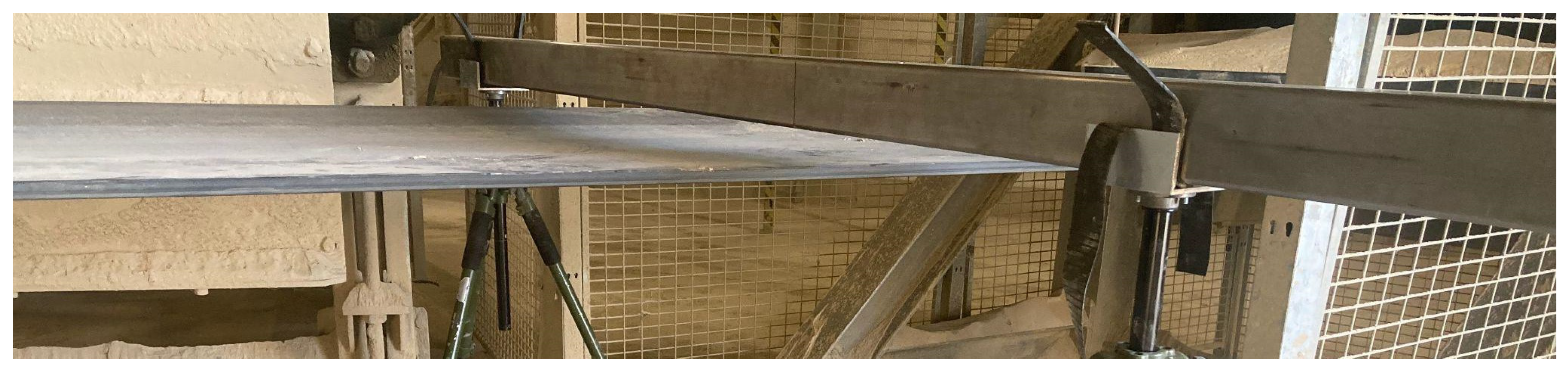
In the magnetic method used in the DiagBelt system, which involves magnetizing the core of the conveyor belt and observing its magnetic properties, inductive sensors are used. The DiagBelt system consists of a measurement head with 40 coils per meter of active length (evenly spaced at 25 mm intervals) and two permanent magnet heads positioned above and below the examined belt, approximately 30 mm away from its covers. This device can be installed on both the upper and lower branches of the belt. The measuring head is designed to operate in a wide temperature range (from −25 to +70 °C) and under humidity conditions up to 95% [
64].
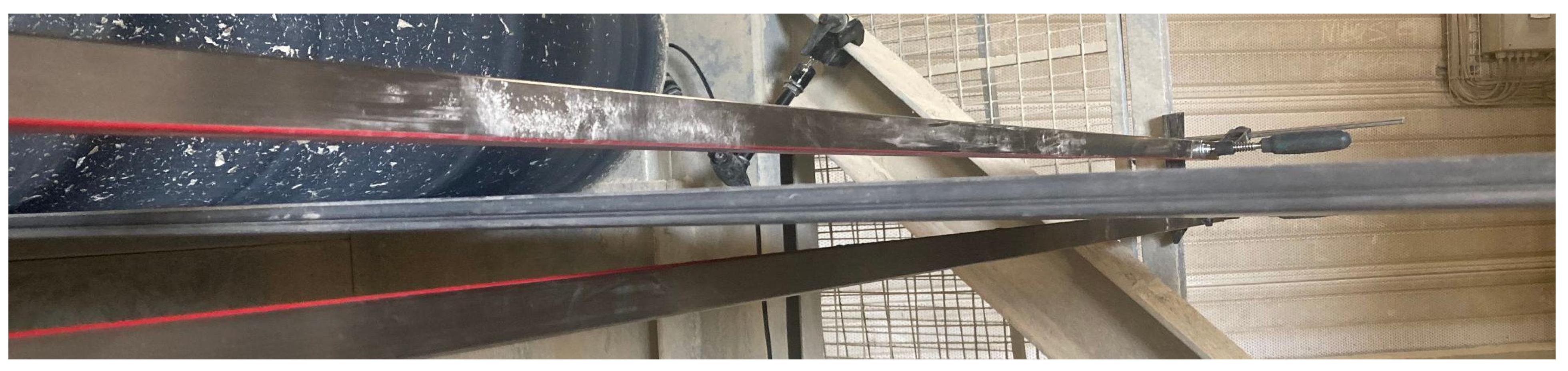
Figure 1 and
Figure 2 illustrate the mounting method of the DiagBelt measurement system on one of the conveyors in industrial conditions.
During the movement of the belt beneath the measuring head, the coils detect changes in the magnetic field caused by discontinuities in the steel cables. The measurement signals are amplified, collected in a data-recording module, and then transmitted to a computer. The DiagBelt system allows for the adjustment of coil sensitivity and measurement frequency to customize the inspection according to individual needs. Measurement results are saved in a CSV file, enabling the analysis of the technical condition of the belt core.
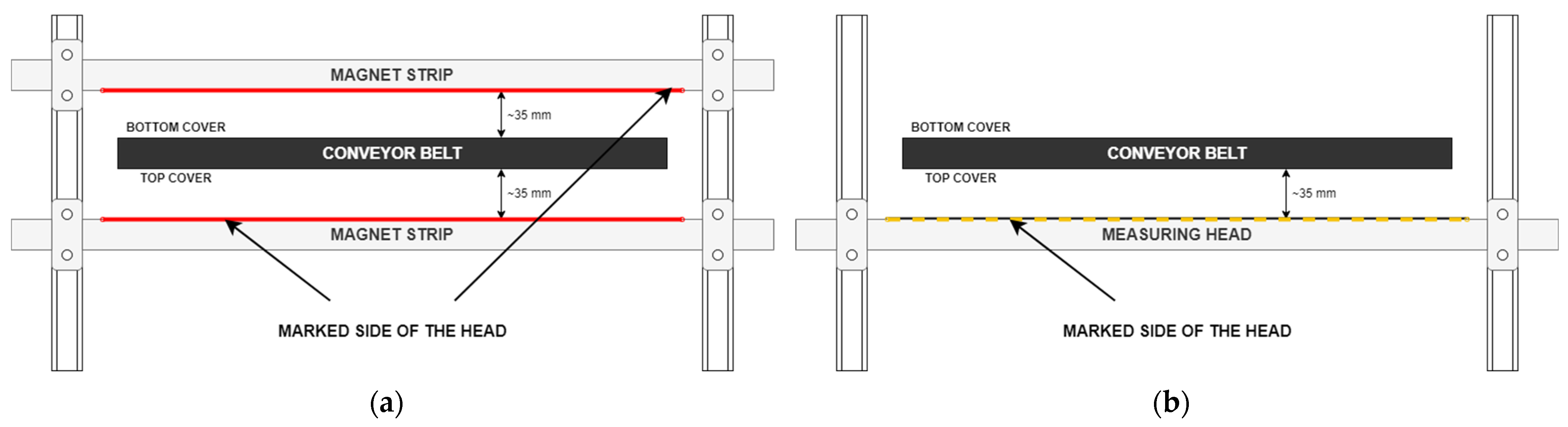
During belt loop scans, magnetizing strips are installed above and below the belt at equal distances from the covers, ideally 30–40 mm. To register cable inconsistencies or loss of metal cross-section, steel cables must be magnetized in advance. Magnetizing strips perform several cycles of belt movement (about 6–8).
Figure 3 illustrates the installation scheme of permanent magnet strips and the measuring head.
2.2. Object of Research Characterization
The DiagBelt diagnostic system was applied to a series of conveyors operating in one of the coal mines in Poland. The analyzed lignite surface mine is situated in the central part of Poland. Overburden (about 130 million m
3/annum) and lignite (about 40 million of Mg/annum) is excavated by bucket wheel excavators on several levels. The depth of mining operations in the Bełchatów field is about 300 m and the average calorific value of the fuel is 8070 kJ/kg. Overburden is transported to spreaders in the inner dump and brown coal (8070 kJ/kg) is transported to the power plant (up to 5.3 GW) and the nearby storage. Hundreds of belt conveyors are used for transportation. Total length of the belts amounts to hundreds of kilometers. Electricity produced at this power station covers about 20% of domestic power consumption (
https://euracoal.eu/info/country-profiles/poland/ (accessed on 17 December 2023)). The scale of transport operations explains the need to apply NDT diagnostic methods. Due to frequent changes made to the belt loops (segments or conveyors being dismantled and relocated), only two conveyors were examined multiple times at different intervals, one four times and the other twice. Conveyor A, with a loop length of 2021 m, was examined four times: in September 2021, September 2022, October 2022, and May 2023. In November 2022, five segments indicating the need for refurbishment were dismantled from the conveyor and replaced with other segments that already had a work history. Specifications of the conveyor belt working on this conveyor: the belt transports overburden, has a loop length of 2021 m, operates at a speed of approximately 6 m/s, and is of St type with a nominal strength of 3150 kN/m and a width of 2.25 m. The theoretical efficiency of this conveyor is 14,700 m
3/h, with actual working time in 2022 being 6488 h and the actual output in 2022 reaching 3922 m
3/h.
Table 1 presents the lengths of the segments and the dates of their initial installation on the conveyor belt.
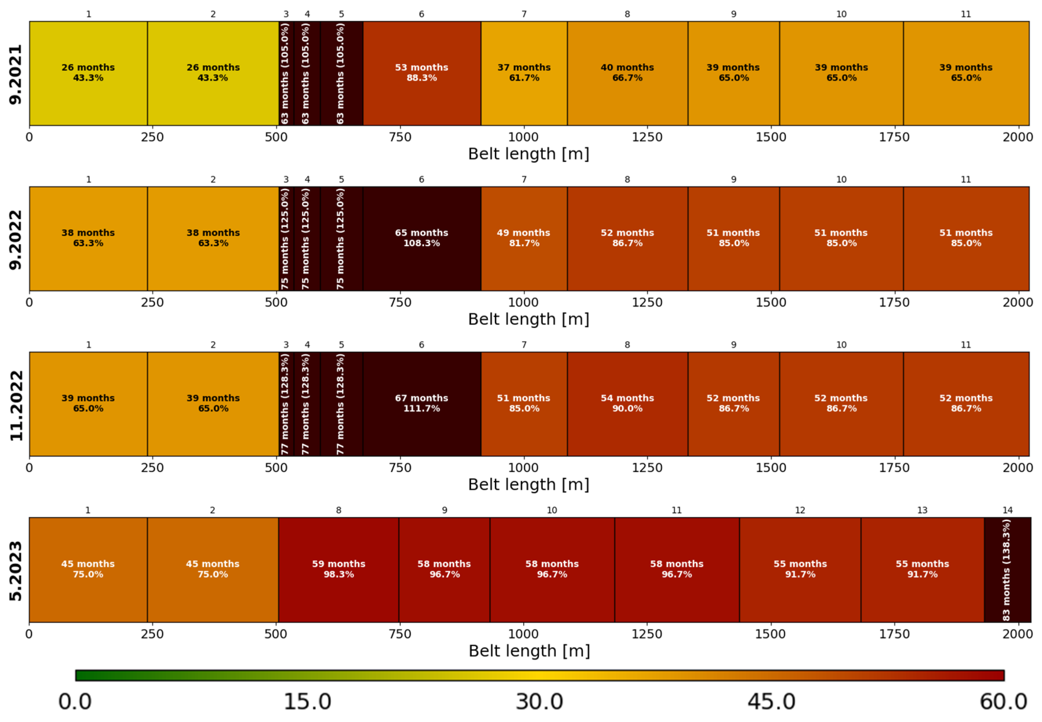
Visualization of the age of individual belt segments (segment color on a chart in relation to the work time forecast) and the lengths of segments in the loop (segment width) for the belts operating on Conveyor A in consecutive examinations is shown in
Figure 4.
3. Obtained Results and Their Analysis
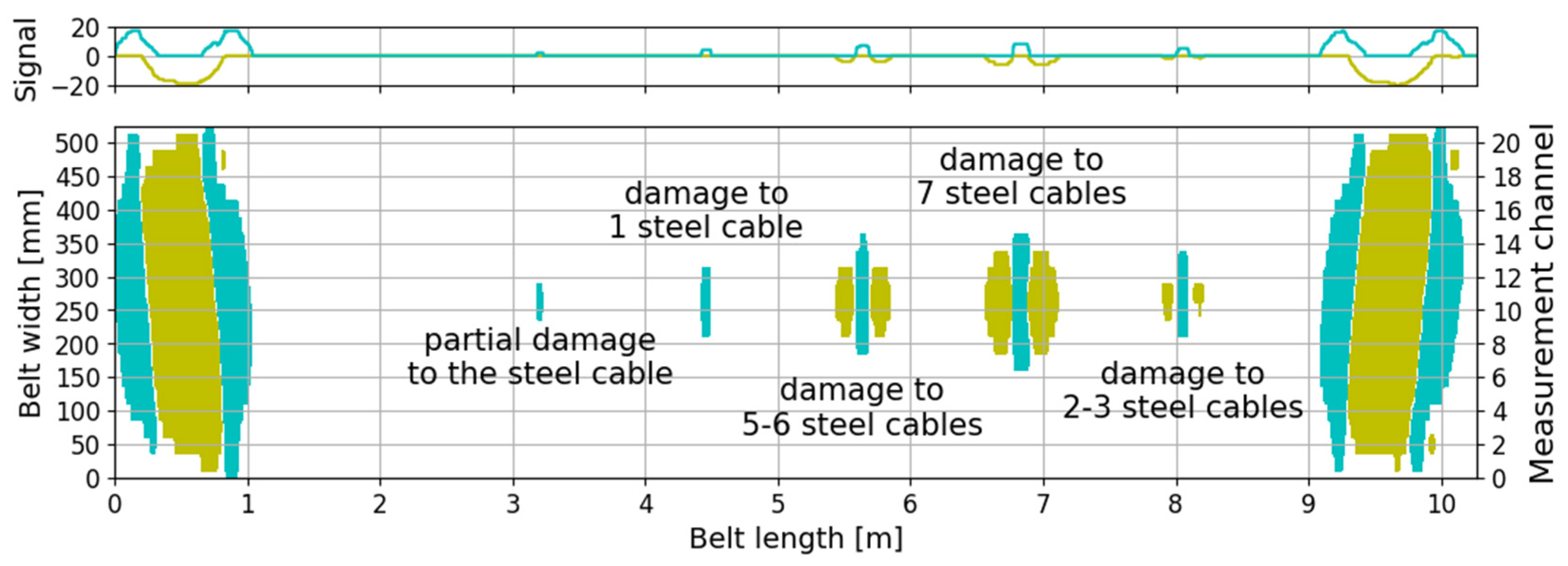
From the analyzed data in the form of quantized signal values (−1, 0, or 1), the locations of the damage were determined. Based on previous studies, it was determined that the occurrence of damage is indicated by the presence of a signal with positive polarization (represented in blue color in the figures). An example of a measurement signal at the location of various types of cable discontinuities is shown in
Figure 5.
Depending on the size of the damage, the distance between the measurement head and the conveyor belt, the belt speed, and the set sensitivity threshold, the signals of the failures can vary. Years of experience in assessing the technical condition of the conveyor belt core using the magnetic method have allowed for the selection of appropriate measurement parameters [
65], such as the distance between the measurement head and the belt surface and sensitivity settings, specific to each working belt with its speed, wire diameter, and spacing between wires.
Minor defects, such as partial wire damage, generate a damage signal visible as a cluster of blue dots on only a few measurement channels. As the size and complexity of the damage increase, the registered magnetic field change extends (blue signal in
Figure 5) (increasing its longitudinal and transverse extent), and two accompanying clusters of dots with the opposite polarity of magnetic field changes appear (yellow signal in
Figure 5). It is observed that small failures generate small signals, visible as a blue cluster of dots, while significantly larger failures exhibit the presence of two neighboring clusters marked with yellow. Although the damage signal may consist of three clusters of dots, only the cluster located in the center, marked with blue color, indicates the location of the damage. For this reason, further analysis considers only the core signals, represented by the cluster of dots in the center (blue signal with positive polarity), in order to accurately determine the location and longitudinal/transverse extent of the damage.
Large clusters of points appearing across the full width of the belt (as shown in
Figure 5 around meter 0.5 and 9.5) represent signals from the belt splice. These are characterized by the opposite polarization of the signal compared to the damage signal—the yellow cluster of points is located in the center, surrounded by clusters of blue points. The extent of the damage being presented and analyzed below is a parameter that takes into account not only the occurrence of the damage but also its length (or width). This parameter refers to a one-dimensional size of the damage, making it a more comprehensive measure than simply counting the number of failures. If a damage signal has a length of 20 mm (small damage), its longitudinal extent is 20, indicating the length of the damage along a 20 mm segment of the belt. In the case of a signal with a length of 75 mm (medium-sized damage), the longitudinal extent is 75. Similarly, for the transverse extent, it is measured not in millimeters but rather in terms of the measurement channels (adjacent measurement channels are spaced 25 mm apart). Unlike a simple count of failures, where each damage is treated as equally significant, the extent of the damage allows for considering the difference between small and large failures. Small failures, such as cutting a few cords or corrosion, have a lower value of the extent parameter compared to larger failures, such as cutting or missing several cords, because their signal is smaller. The extent of the damage takes into account the size of the damage itself, enabling a more comprehensive assessment of the technical condition of the belt core. By considering the dimensions of the damage, the extent becomes a more representative indicator of the belt’s condition.
In the context of diagnostic research on belt conveyors, considering the extent of the damage allows for a more precise monitoring and assessment of the belt’s condition. This is particularly important as it enables the early detection and response to significant defects that may lead to failures or serious operational issues. By incorporating the extent parameter, the diagnostic system can provide more accurate insights into the state of the belt, helping operators detect potential problems at an early stage and take appropriate actions to prevent further damage or operational disruptions.
In
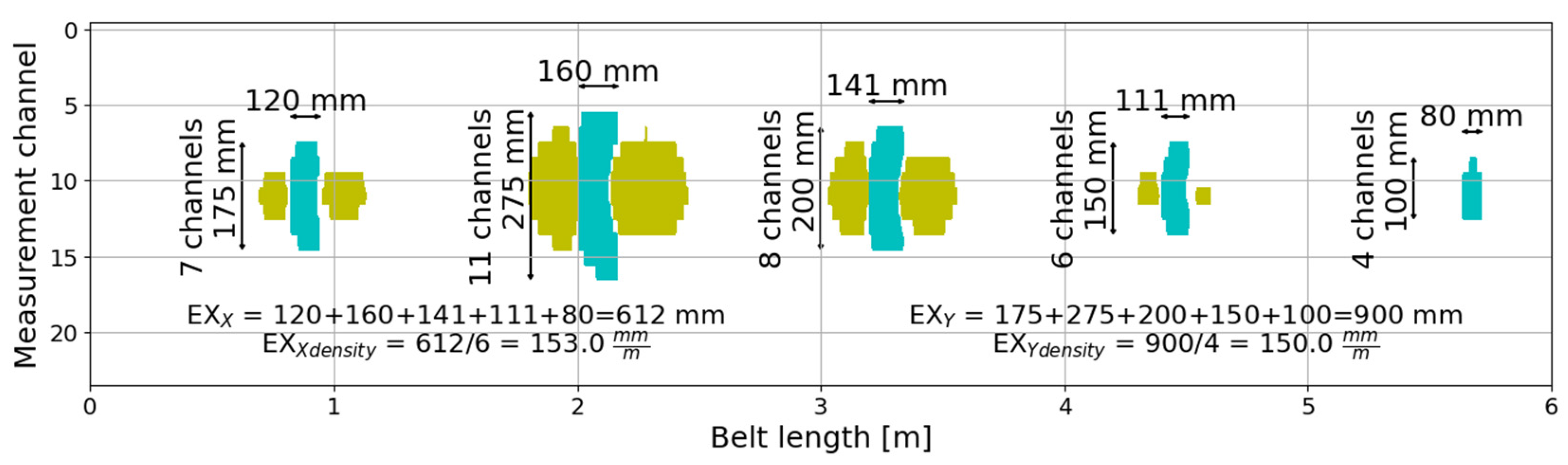
Figure 6, an example of calculating the longitudinal and transverse extent of failures based on the measurement signal is presented.
To assess the technical condition of the conveyor belt, the sum of longitudinal extent and transverse extent of the damage signal was considered, which corresponds to the size of the failures. The total extent of damage along a segment is the sum of all failures’ lengths in the case of longitudinal extension or their widths in the case of transverse extension. Both values were used to obtain a more comprehensive distribution of failures along the entire belt. Formulae (1)–(2) were defined to calculate the parameter of longitudinal/transverse extent on a given belt segment.
where:
—longitudinal extent, mm,
transverse extent, mm,
—number of failures in the segment,
—length of the -th failure in millimeters,
—width of the -th failure in millimeters.
In order to account for the varying length of the belt due to repairs (cutting out the most worn segments, belt shortening), the extent of failures was averaged per linear meter of the belt. This approach took into consideration that the number of failures is strongly and positively correlated with the length of individual belt segments. The longer the segment is, the more failures, on average, appear on it. To compare segments of different lengths, the determined extent was converted to linear meters of the belt by dividing it by the segment’s length. The density of extent can be expressed using Formulae (3)–(4).
where:
—density of longitudinal extent, ,
density of transverse extent, ,
—length of the segment in meters.
The density of extent, therefore, is a parameter with the dimension of . Dividing the obtained values by 1000 could represent a dimensionless quantity. However, from a practical standpoint, using the unit of for the size of failures (or their increments) is easier to interpret.
With the passage of time, an increase in the density of extent can be observed for two reasons. Firstly, new failures appear, initially small in size (such as corrosion or damage to a few wires), while existing ones continue to grow. These new failures add up to the existing ones, leading to an overall increase in the total extent (longitudinal or transverse) on a specific segment of the belt. Secondly, older failures tend to enlarge over time during operation. Initially, small failures may gradually develop and widen, increasing their longitudinal and transverse extent. The increasing extent of the failures contributes to the growth of the extent density. As a result, both the appearance of new defects and the enlargement of existing ones contribute to a gradual increase in the density of extent over time.
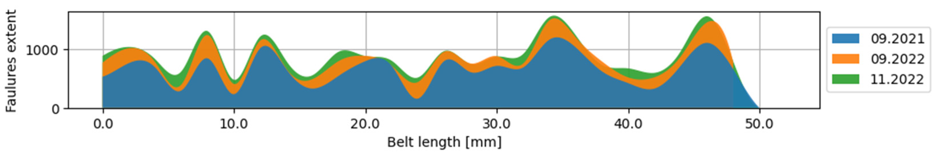
Figure 7 and
Figure 8 present an example of smoothed longitudinal extent profiles for two selected segments of the tested belt—one of them measured four times and the other measured three times. It is important to emphasize that the diagnostic device is mounted independently on each conveyor, and, therefore, its initial setup (including the precise adjustment of the measurement head distance from the belt) and lateral displacement of the belt can affect the obtained results, showing a slight decrease in extent on a specific meter of the belt, which is visible in the extent of the adjacent meter.
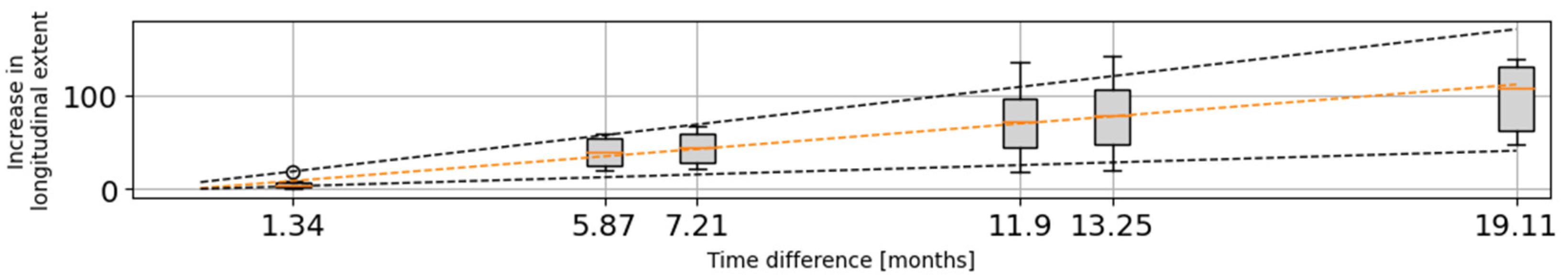
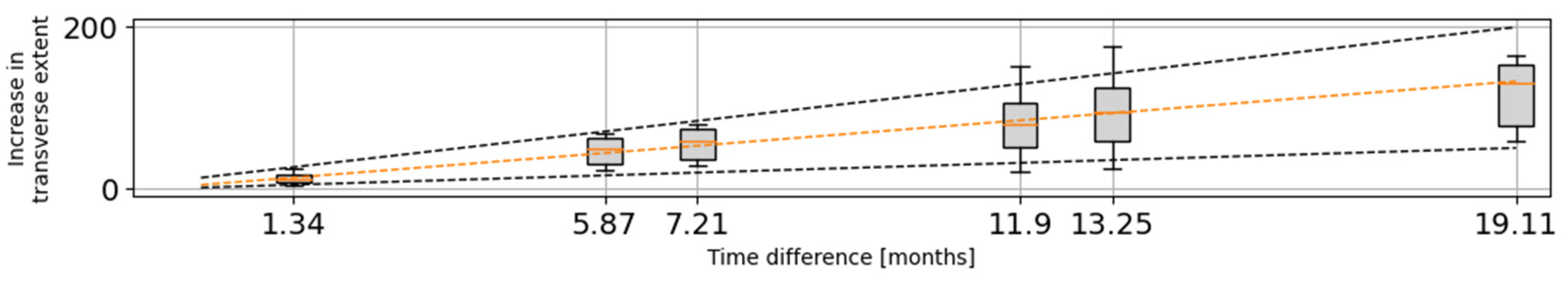
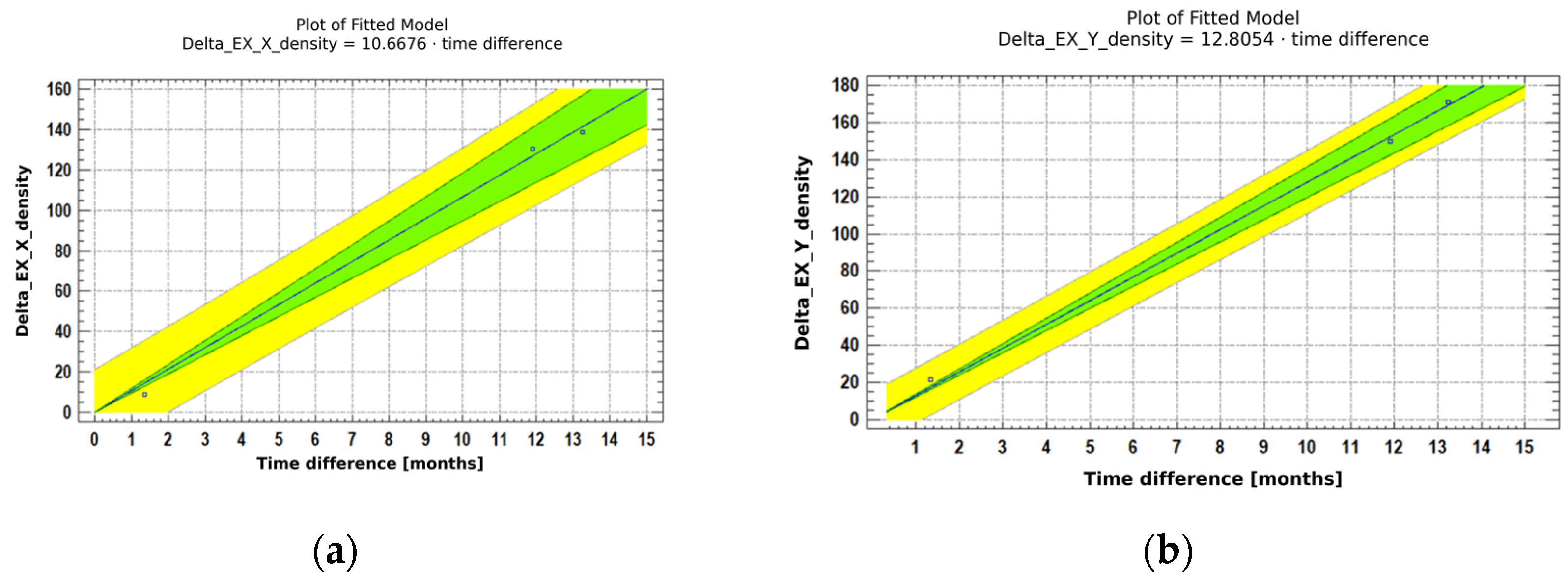
The box-and-whisker plots presented in
Figure 9 and
Figure 10 depict the results used for further analysis of the extent expansion of failures over time. The Y-axis of these plots represents the increase in extent—longitudinal (
Figure 9) and transverse (
Figure 10). The X-axis represents the difference in time between measurements expressed in months. Additionally, straight lines have been included in the plots, illustrating the linear pace of damage expansion. The dashed orange line corresponds to the rate determined based on the median, while the dashed black lines represent the linear rate of failures’ expansion using data from the upper and lower extremes.
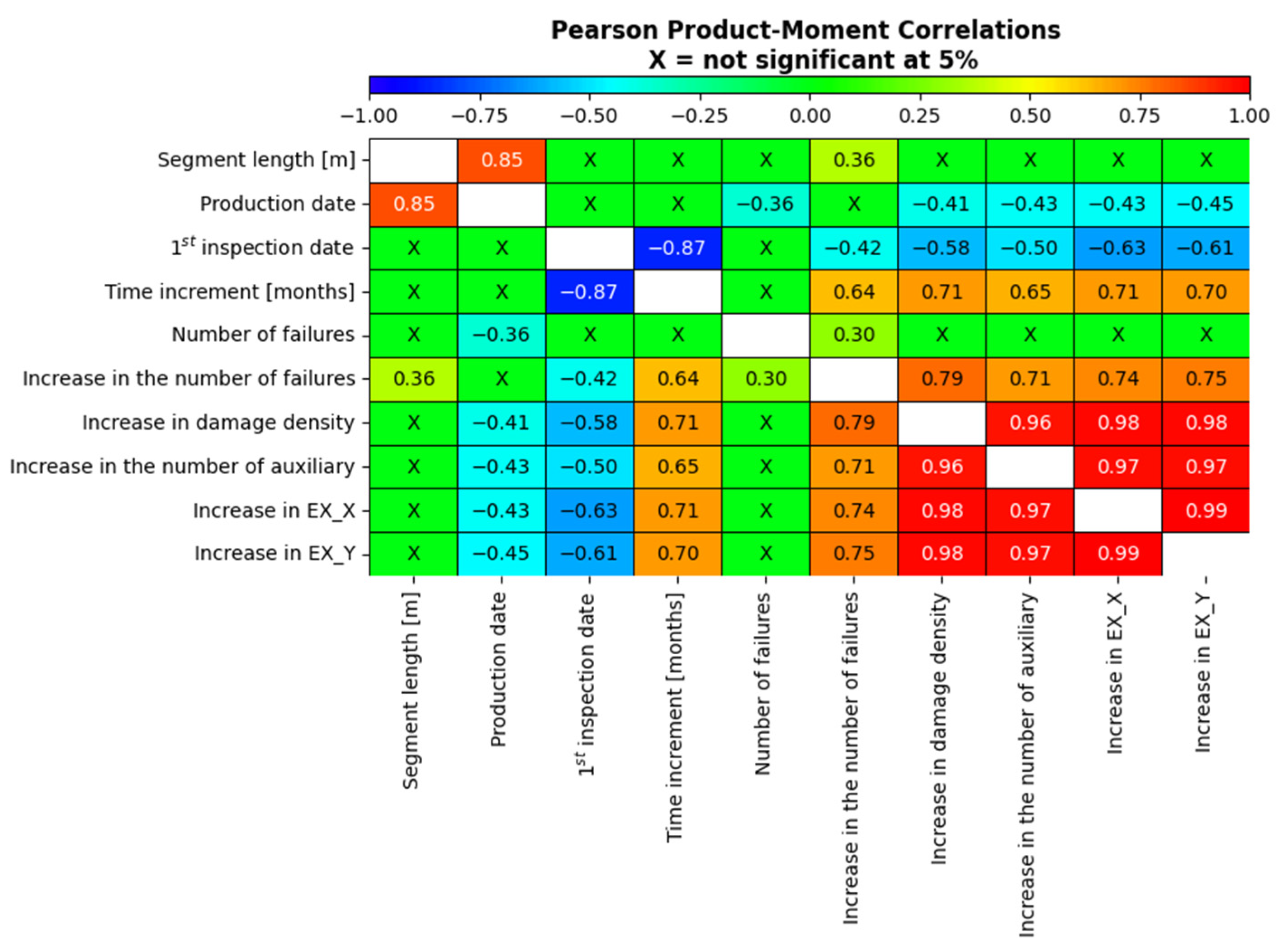
All statistical analysis presented in the article was performed using the Statgraphics Centurion XVIII program licensed to Wroclaw University of Science and Technology. The first step of the analysis was to determine the coefficients of linear Pearson correlation between various parameters under investigation. The data vectors taken into account included the following:
Segment length [m]—the length of the segment,
Production date—the production date of the belt (indicating the start of operation),
First inspection date—the date of the first inspection for which the changes were analyzed,
Time increment—the time difference between inspections,
Number of failures—the number of identified clouds of points corresponding to the defect,
Increase in number of failures—the growth in the number of failures between two considered inspections,
Increase in damage density—the growth in the damage density (number of failures divided by segment length) between two considered inspections,
Increase in number of auxiliary—the growth in the number of identified accompanying signals,
Increase in EX_X—the growth in the longitudinal extent between two considered inspections,
Increase in EX_Y—the growth in the transverse extent between two considered inspections.
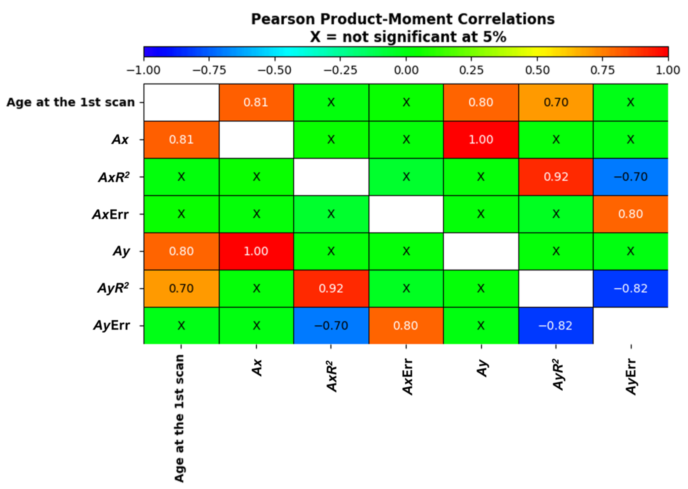
The correlation values were presented in
Figure 11. The analysis of correlations allowed for the proper definition of indicators describing failures, as it facilitated the understanding of the relationships between the analyzed parameters. For example, converting the number of failures to a density of failures is due to the variation in the length of belt segments in the loop. The probability of failures occurring in the core of each segment due to the penetration of the belt and wires (e.g., in the area of large boulder drops on the conveyor) depends on the duration of exposure to this hazard, which, in turn, depends on the belt speed and the length of the segments. The belt speed is the same for all segments in the loop, so the length of the segments is the main factor influencing the change in the number of failures. Even when the belt speed is variable (which did not occur in this case), its changes affect all belt segments in the loop equally, as they randomly interact with the segments in the loop due to the random arrangement of the loop at the time of changes. The total number of failures or accompanying signals depends on the length of the segments. To facilitate comparison across different segments, relative measures like the average number of failures per meter of the belt segment (failure density) were introduced. The same approach was applied to other averaged indicators (measures) related to the increases between scans (measurements), allowing for their comparison. It was found that the relative increase rates depend on the age of the belt. This is not surprising, as the resistance of the belt decreases with the extension of operating time. The belt is an aging object. The intensity of failures increases because, as a result of friction processes, the thickness of the belt covers decreases, which reduces the critical energy required for a significant failure of the belt and core (e.g., cutting of steel cords). Additionally, fatigue processes occurring in the core weaken it, causing wire breakage in the cords, reducing the adhesion of the core [
10].
The fact that the length of belt segments was positively and statistically significantly (albeit weakly) correlated with the increase in failures confirms the need for a relative measures analysis. The increase in the number of failures for longer segments is an expected result based on previous explanations. The weak correlation strength is due to the limited variation in the lengths of belt segments in the loop. The date of the first inspection was negatively correlated with all relative indicators of failure increments (on average), with the strongest correlation observed for the time difference. The earlier the inspection was conducted, the more distant in time the execution of the second inspection could be. If the first inspection was conducted recently, the time increment to the second inspection had to be smaller.
The positive correlation between the length of the belt segment and the production date (representing the moment when the belt started working) is due to the fact that the latest installed segments (the youngest ones) are the longest (approximately 250 m). The earliest installed segments (the ones that have been in operation the longest) undergo multiple repair processes (e.g., inserting fragments) and shortening (cutting off the most damaged segments), and each connection replacement results in the loss of belt ends to make the connection (
Figure 12). These processes have been described in [
5]. Undoubtedly, analyzing relative measures (per 1 m) describing changes in failures over time should facilitate comparisons.
Indeed, it is worth investigating whether the elapsed time from the start of operation (production date) affects the degradation processes of belt segments, considering its evident influence on the shortening of segments due to damage removal.
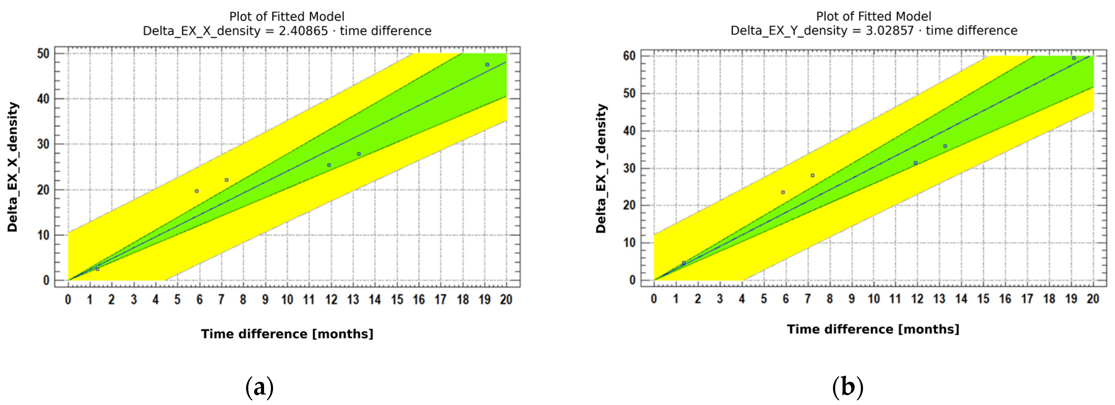
Linear Regression Analysis of Increases in Damage Extent in Both Directions
Analyses of average regression of extent along the belt axis (
) and across the axis (
) were conducted for all belt segments in the loop. The analysis will be presented for both younger (
Figure 13) and older (
Figure 14) belts to provide illustrations, and the consolidated results will be presented in a
Table 2.
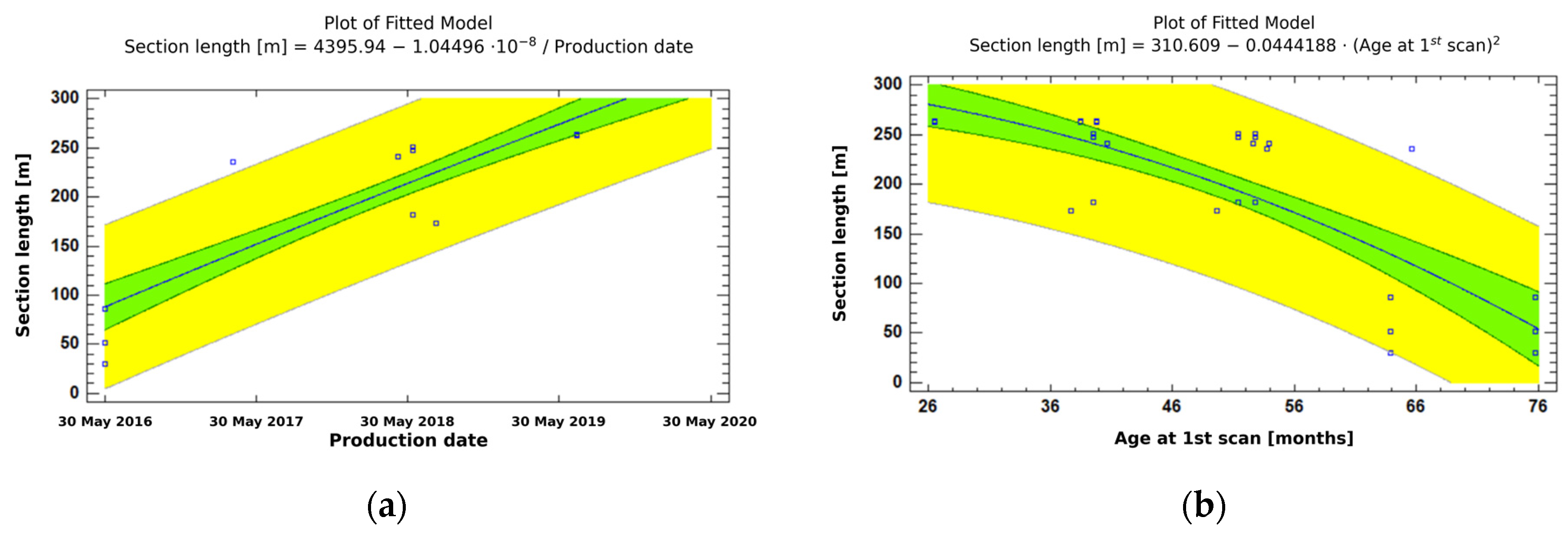
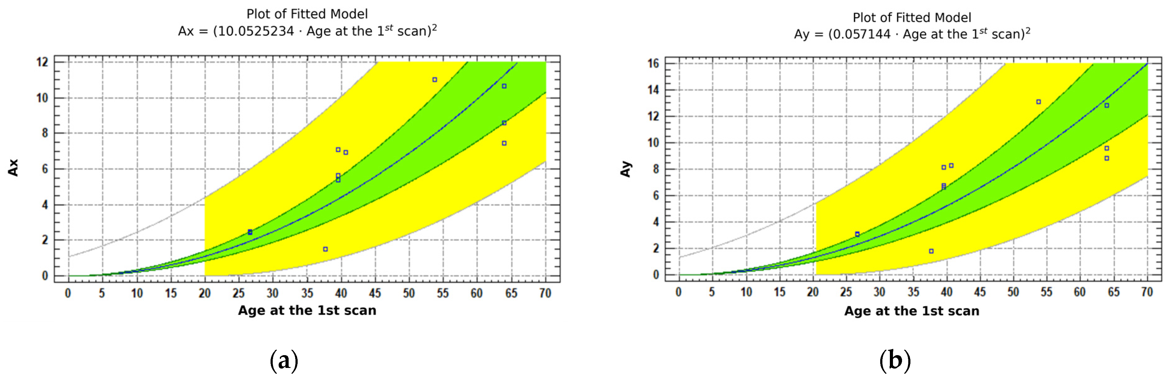
The influence of belt age on the rate of damage progression can be examined by fitting regression curves to the data from
Table 2 (
Figure 15).
Both charts show the results of fitting square root models to describe the relationship between
(left side) and
(right side) and age of belt segments at the first scan. The equations of the fitted models are shown in Equations (5) and (6):
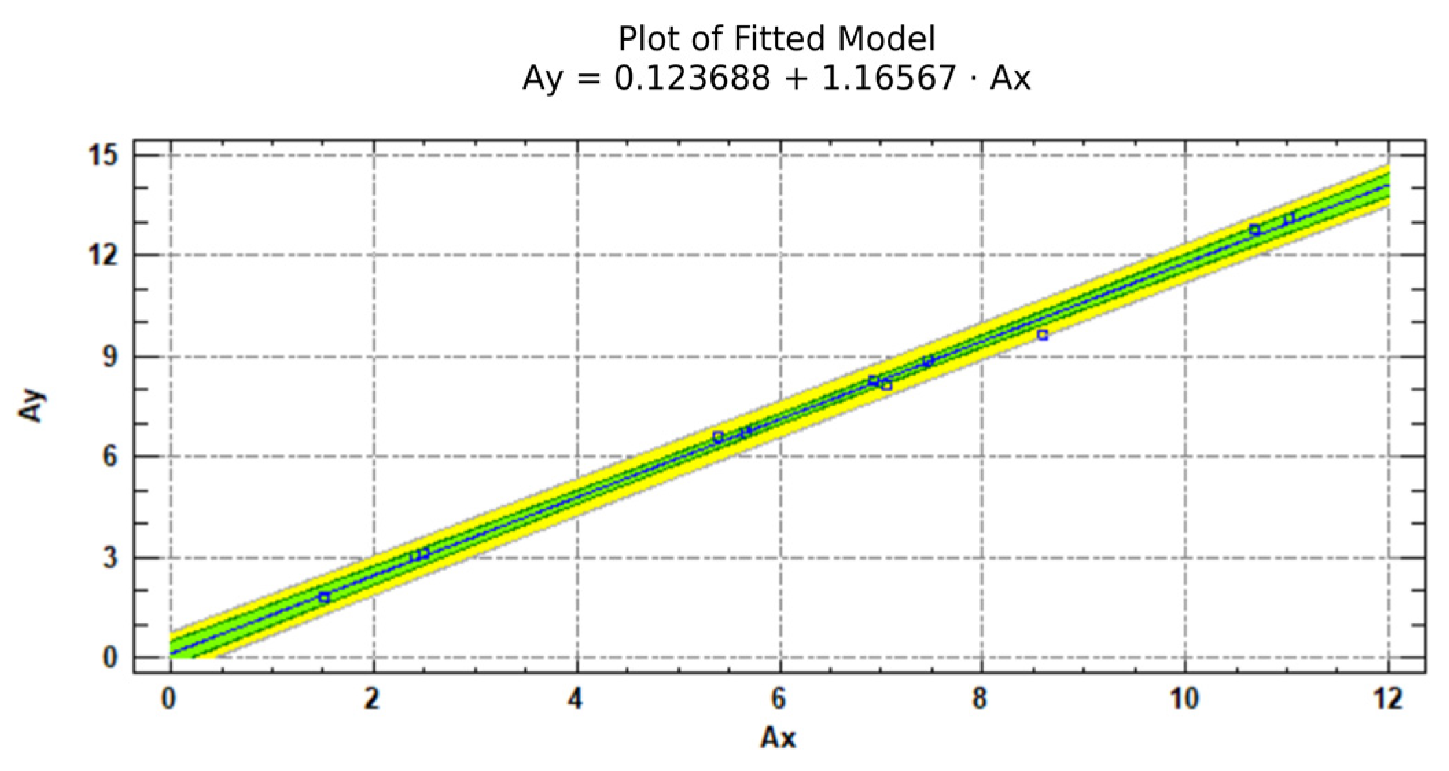
Both models are very similar. Parameter
is slightly greater than
for all belt segments (
Figure 16).
This can be explained by the type of textile breaker embedded in the belt—its bundles are arranged across the belt, facilitating water movement across the belt and the enlargement of failures in this axis. Along the belt axis where water reaches the core, it migrates towards the alignment of the cords (thus, along the belt), enlarging failures along the OX axis.
Since the p-values in the ANOVA tables are less than 0.05, there are statistically significant relationships between () and at the 95.0% confidence level.
The statistics indicate that the model as fitted explains 96.8552% () and 96.7213% () of the variability in both analyzed parameters transforming to a logarithmic scale to linearize the model. The correlation coefficient equals 0.9841 () and 0.98347 (), indicating a relatively strong relationship between the variables. The standard error of the estimate shows the standard deviation of the residuals to be 0.466598 () and 0.518701 (). These values can be used to construct prediction limits for new observations.
The mean absolute error (MAE) of 0.395003 () and 0.445727 () are the average values of the residuals. The Durbin–Watson (DW) statistic tests the residuals to determine if there is any significant correlation based on the order in which they occur in your data file.
A very high correlation can be observed between
and
(with a value of 1 on the graph, confirming the relationship mentioned in
Figure 16). The coefficients
and
depend on the age of the belt at the time of the first of the two belt inspections. A slightly lower correlation with age is observed for the R
2 value of
. This
value is also correlated with its counterpart for
, and inversely correlated with the relative error for
, and, vice versa, the
value for
is inversely correlated with the error for
. Both errors for
and
are positively correlated with each other.
4. Discussion and Conclusions
The article presents a methodology for analyzing the rate of increase in the number and size of failures based on four scans of the condition of steel cable belts in a lignite coal mine in Poland using the DiagBelt+ system. To eliminate the influence of varying segment lengths in the loop, aggregated measures of damage size per linear meter of the belt were proposed. The long-term use of conveyor belts, combined with random failures events such as punctures and cuts, necessitates repairs, replacement of segments, and shortening (e.g., after damage or connection replacement) to remove the most damaged parts and ensure safe operation. Consequently, the number of connections increases, segment lengths vary, and their age changes. Initially, each loop of the conveyor system consisted of a minimum number of new segments of the maximal length to minimize the number of splices.
Introducing diagnostic systems into the daily operation of conveyor belts is crucial for effective management and minimizing production losses. Diagnostic monitoring of the belt’s technical condition provides detailed insights into its wear and tear, enabling prompt and effective corrective actions. With this information, businesses can extend the service life of conveyor belts, reducing unplanned downtime and associated production losses. Furthermore, the implementation of diagnostics allows for precise replacement planning, promoting rational budget management and avoiding situations where production is halted due to a lack of access to new belts. In the face of growing demand for mineral resources, diagnostic implementation becomes a key tool in meeting the evolving requirements of the mining sector. Ultimately, investments in conveyor belt diagnostics not only enhance the reliability of transportation systems but also contribute to optimizing production processes, concurrently supporting sustainable development goals.
The performed analysis revealed that the linear rate of failure size increase (total longitudinal and transverse extension) grows with the age of belt segment (i.e., time of its operation). The short-term (e.g., annual) forecasts of relative failure size increases ( and ) can be forecasted using linear functions based on their identified state in the last magnetic inspection. The diverse age of individual belt segments requires individually tailored rates of change. Regression analysis demonstrated that the rate of change of slope coefficients and in linear forecasts can presented by a quadratic function of belt segment age.
By utilizing the values
and
, it is possible to determine the relationship of the increment parameter for longitudinal or transverse extent density over time in accordance with Equations (7)–(10):
The determined parameters and from the selected models can be used to generate short-term forecasts of the average increase in longitudinal extent () and transverse extent () after scanning the loop of a specific conveyor belt. The current values of the indicators (longitudinal and transverse extent) will be determined by the DiagBelt+ system, and the forecast of further increases (increments) for the next period after scanning can be made using the selected models. It is important to note that the belt loops consist of multiple segments of varying lengths and ages. By applying regression curves to each segment, the appropriate slope coefficients can be determined, and linear increments of the proposed relative measures can be calculated. If the sum of the current state and increments exceeds the allowable damage threshold during the forecast period, the number of replacements, as well as the timing and schedule of belt requirements, can be determined. This approach enables the implementation of a rational replacement policy for belt segments based on the identified state and a forecast derived from detailed statistical analysis of the rate of changes.
The obtained results have practical significance. Conducting similar analyses for each conveyor system in the mine that has been inspected at least three times in the past allows for the determination of the future condition of all belt segments in the examined loop by adding extrapolated increments to their identified state in the current inspection. Many belt replacement policies, including those related to refurbishment, are based on reaching the belt segment condition critical threshold level (e.g., defined for the proposed measures) tailored to each policy. Due to the variation in the duration of service (age) of belt segments in the loop, forecasts need to be individually adjusted. The methodology described in the study facilitates such an approach.
As the number of conveyors scanned at multiple time intervals increases, more data will be available on the factors influencing the rate of change in the number and sizes of failures. This will enable multidimensional correlation analysis (construction of multicriteria models) and the application of artificial intelligence.
It is worth noting that the conducted research confirms the need for computerized databases that would store information on the condition of belt segments from recent inspections as non-invasive research methods, such as the DiagBelt+ magnetic system, to be implemented. In Polish lignite coal mines, such systems are in operation since the mid-1980s, providing access to data on belt usage time, segment lengths in the loop, connections made, and repairs conducted. Information on belt age and segment lengths (which can be determined during scanning) is essential for accurately adjusting the rates of belt condition changes. It is valuable to expand these databases with information obtained during scanning.
Future perspectives include further research on aligning mathematical models and enhancing their accuracy by expanding the database, and exploring various sensitivity thresholds and belt speeds. Additionally, ongoing efforts are focused on developing damage classification algorithms using artificial intelligence methods, resulting in a more precise assessment of the core belt’s technical condition. Simultaneously, work is in progress to utilize AI mechanisms for predicting the technical state of the core based on parameters such as section length, belt age, current condition, operating speed, and the type of conveyed material. Ultimately, these endeavors aim to improve the reliability and efficiency of the DiagBelt+ system.


