Article

Studying Flotation of Gold Microdispersions with Carrier Minerals and Pulp Aeration with a Steam–Air Mixture

by
Sergei Ivanovich Evdokimov
1,
Nikolay S. Golikov
2,*,
Alexey F. Pryalukhin
2,*,
Viktor V. Kondratiev
3,
Anatolii Mishedchenko
4,
Alexandra Vl. Kuzina
5,
Natalia Nikolaevna Bryukhanova
3 and
Antonina I. Karlina
6
1
Department of Mineral Processing, North Caucasian Institute of Mining and Metallurgy, State Technological University, 362021 Vladikavkaz, Russia
2
Department of Mechanical Engineering, Saint-Petersburg Mining University, 199106 St. Petersburg, Russia
3
Laboratory of Geochemistry of Ore Formation and Geochemical Methods of Prospecting, A. P. Vinogradov Institute of Geochemistry of the Siberian Branch of the Russian Academy of Sciences, 664033 Irkutsk, Russia
4
Faculty of Urban Studies and Urban Economy, Moscow Polytechnic University, 107023 Moscow, Russia
5
Department of Technique and Technology of Mining and Oil and Gas Production, Moscow Polytechnic University, 107023 Moscow, Russia
6
Stroytest Research and Testing Center, Moscow State University of Civil Engineering, 129337 Moscow, Russia
*
Authors to whom correspondence should be addressed.
Minerals 2024, 14(1), 108; https://doi.org/10.3390/min14010108
Submission received: 5 January 2024 / Revised: 15 January 2024 / Accepted: 16 January 2024 / Published: 19 January 2024
(This article belongs to the Special Issue Design, Modeling, Optimization and Control of Flotation Process)

Abstract

:
This work is aimed at obtaining new knowledge in the field of interactions of polydisperse hydrophobic surfaces in order to increase the extraction of mineral microdispersions via flotation. The effect of high velocity and the probability of aggregating fine particles with large ones are used to increase the extraction of finely dispersed gold in this work. Large particles act as carrier minerals, which are intentionally introduced into a pulp. The novelty of this work lies in the fact that a rougher concentrate is used as the carrier mineral. For this purpose, it is isolated from three parallel pulp streams by mixing the rougher concentrate, isolated from the first stream of raw materials, with an initial feed of the second stream; accordingly, the rougher concentrate of the second stream is mixed with the initial feed of the third stream, and the finished rougher concentrate is obtained. In this mode of extracting the rougher concentrate, the content of the extracted metal increases from stream to stream, which contributes to the growth in its content in the end product. Moreover, in order to supplement forces involved in the separation of minerals with surface forces of structural origin in the third flotation stream, the pulp is aerated for a short time (about 15%–25% of the total) with air bubbles filled with a heat carrier, i.e., hot water vapor. Within this accepted flotation method, the influence that the surface currents occurring in the wetting film have on its thinning and breakthrough kinetics is proposed to be in the form of a correction to a length of a liquid slip in the hydrophobic gap. The value of the correction is expressed as a fraction of the limiting thickness of the wetting film, determined by the condition of its thickness invariability when the streams are equal in an interphase gap: outflowing (due to an action of the downforce) and inflowing (Marangoni flows and a thermo-osmotic stream). Gold flotation experiments are performed on samples of gold-bearing ore obtained from two deposits with conditions that simulate a continuous process. Technological advantages of this developed scheme and a flotation mode of gold microdispersions are shown in comparison with the basic technology. The purpose of this work is to conduct comparative tests on the basic and developed technologies using samples of gold-bearing ore obtained from the Natalka and Olimpiada deposits. Through the use of the developed technology, an increase in gold extraction of 7.99% and in concentrate quality (from 5.09 to 100.3 g/t) is achieved when the yield of the concentrate decreases from 1.86 to 1.30%, which reduces the costs associated with its expensive metallurgical processing.

1. Introduction

The main peculiarity of ores currently involved in processing is the increased content of small fractions of extracted valuable components in them [1]. For example, the proportion of disseminated gold contained in sulfide minerals (such as pyrite or arsenopyrite) can reach up to 15%–35%. Taking into account peculiarities of the material composition of currently processed ores, a strategy for the development of the mineral resource base of the Russian Federation until 2035 has been established. It provides for improvements in the theory and methods of extracting and enriching solid mineral raw materials of natural and technogenic origin [2]; in particular, flotation technology [3] represents one of the main processes for the primary processing of the majority of ore [4] and non-metallic minerals.
In the case of the traditional approach to the problem of effectively extracting fine particles (whose size does not exceed 10–30 µm) via flotation, a flotation complex formation has been investigated using a thermodynamics apparatus, which considers the physical and chemical patterns of the action of applied flotation reagents [5]. This approach is the most rational when solving technological problems, for example, water treatment, when the completeness of a collective extraction of all solid particles present in an aqueous phase is a necessary and sufficient condition. During ore flotation, a requirement of the completeness of extracting valuable components is supplemented by a condition of selective separation of minerals [6,7].
During the selective flotation of minerals, the flotation complex is formed as a result of the inertial collision of a particle with a bubble surface. The thinning (when a particle slips along a bubble surface from its upper pole to equator) of a wetting (interphase) film separates a particle and a bubble up to a thickness at which surface adhesion forces acquire a noticeable intensity [8,9] and the formation of the contact angle [10]. Moreover, contact angles should reach values at which the continuous transportation of a particle, adhering to a bubble surface, into a foam layer is ensured under dynamic (turbulent) conditions of the flotation process. A strong adhesion of a particle to a bubble surface is possible with a sufficiently extended wetting perimeter and a large contact angle. Fine particles are fixed in an aft part of a bubble under the action of a hydrodynamic downforce without forming a contact angle in a distant potential pit. When the particle size decreases from 100 to 1 µm, the releasing force decreases 106 times [11]. Selective flotation is possible only with forming a flotation complex according to the first mechanism: when particle sizes decrease, the probability of their non-selective fixation on the bubble surface increases without the contact angle formation.
Increasing the completeness of the extraction of fine (inertialess) particles is achieved by enlarging them, due to introducing polymers or high-molecular flocculants into the flotation system. It happens less often by recharging bubbles and using flotation machines of a special design. Hydrophobic glass beads and crushed copper ore have been used as carrier materials in order to extract graphite microdispersions [12]. When the flotation carrier platform, in the form of hydrophobic chalcopyrite and malachite microdispersions, was approached at a distance of up to 8.6–12.5 nm, significant attractive forces appeared between them due to hydrophobic interactions [13,14,15,16,17,18,19].
In this work, to increase the completeness and selectivity of the extraction of microdispersions of minerals, large particles, or a solid wall, are used, and the rate of adhesion (as well as induction time [20,21]) is two orders of magnitude higher than the rate at which fine particles aggregate among themselves [14]. When studying an aggregation of hydrophobic polydisperse particles, basic mechanisms of the DLVO theory (van der Waals (dispersion) forces and electrostatic interaction) are complemented by “non-DLVO” forces [22,23,24,25,26,27], i.e., surface forces of a structural origin associated with a difference between a water structure of boundary layers and a liquid volume [28,29,30,31,32]. A sweep effect contributes to an increase in the rate of liquid removal from an interphase gap (and, as a result, an increase in an adhesion probability) between hydrophobic particles [32,33,34,35,36,37].
The aim of this work is to study the possibility of increasing the extraction of fine metal fractions from gold-bearing ores using new technological solutions. These are the introduction of carrier minerals and additives to air, supplied for aeration of the flotation system, and a coolant into the pulp, which, from the viewpoint of industrial and environmental safety, fully fits into the context of the Agenda for the field of sustainable development up to 2030, which was adopted by the UN [38,39,40].

2. Methods and Materials

Field experiments on flotation using the developed method were performed with ore samples from the Natalka deposit (Magadan region) and the Olimpiadinsky deposit (Krasnoyarsk region).
To determine the chemical composition of the samples (Table 1), a spark mass spectrometer of the JMS-BM2 type (JEOL, Tokyo, Japan) equipped with inductively coupled plasma (ICP-MS analysis) was used.
According to the scintillation spectral analysis, gold in an ore sample of the Natalka deposit is randomly distributed by size classes. Table 2 shows the results of the scintillation spectral analysis of the gold distribution by size classes in the sample of ores from the Natalka deposit.
Seven ore samples, obtained from the Natalka deposit, were taken. For each of these samples, the purity of gold in that ore was determined by an assay test. An average value of the gold purity was 801 (values in the studied samples ranged from 795 to 807).
In the sample of ores from the Olimpiadinsky deposit, sulfides are represented by arsenopyrite, pyrrhotite and antimonite, placed in a form of an insignificant impurity in a mass of non-metallic minerals: calcite (35%–40%), quartz (30%–43%), muscovite (8%–10%) and biotite (10%–15%), chlorite, sericite and a number of other minerals.
Free gold in ores is represented by finely dispersed and pulverized fractions (Table 3).
Native gold is associated with quartz (35%), arsenopyrite (35%), pyrite and marcasite (15%), pyrrhotite (5%), berthierite and antimonite (5%), carbonates (5%), as well as (single grains) with chalcopyrite, tetrahedrite and muscovite. When grinding ores to a size of 74 µm, the content of free gold is 15%.
A bulk consists of gold grains, whose surface has been subjected to a technogenic impact. Gold is represented by rolled thin plates, whose contours are torn; gold grains of an oblong shape are indicated. A gold color is bright yellow and straw yellow. A surface of individual grains is covered with oxide films. A grain surface texture is mainly bumpy, porous and rough. High-grade gold is 950‰; it contains mercury, silver, copper, iron, antimony, arsenic, sulfur in the form of impurities. A phase analysis of gold in an ore sample was performed (Table 4).
In the flotation experiments, a countercurrent column (D × L = 0.6 × 7.4 m) was used when an initial feed was supplied between a purification zone (1.6 m high) and a mineralization zone (5.8 m high) and the airlift unloading of tailings. During hydraulic transport of tailings, 0.045 m3/(min × m3) of air under a pressure of 0.14 MPa was supplied to an airlift. The reduced pulp velocity (a ratio of a productivity to a column cross-section) was 1.03 cm/s. The steam consumption was 1.07 × 10⁻² kg·s−1·m−2 (under an overpressure of 0.15 MPa) and the air consumption was 2.61 kg·s−1·m−2. The flotation machine was equipped with a confuser–diffuser type aerator when water vapor was supplied (an electric steam generator of an EPG-50 type) to a low-pressure zone created by a working airflow (a compressor of a 4BU1-5/9 type). The gas content in the flotation column was 14%–15%. No rinsing water was applied to the foam layer.

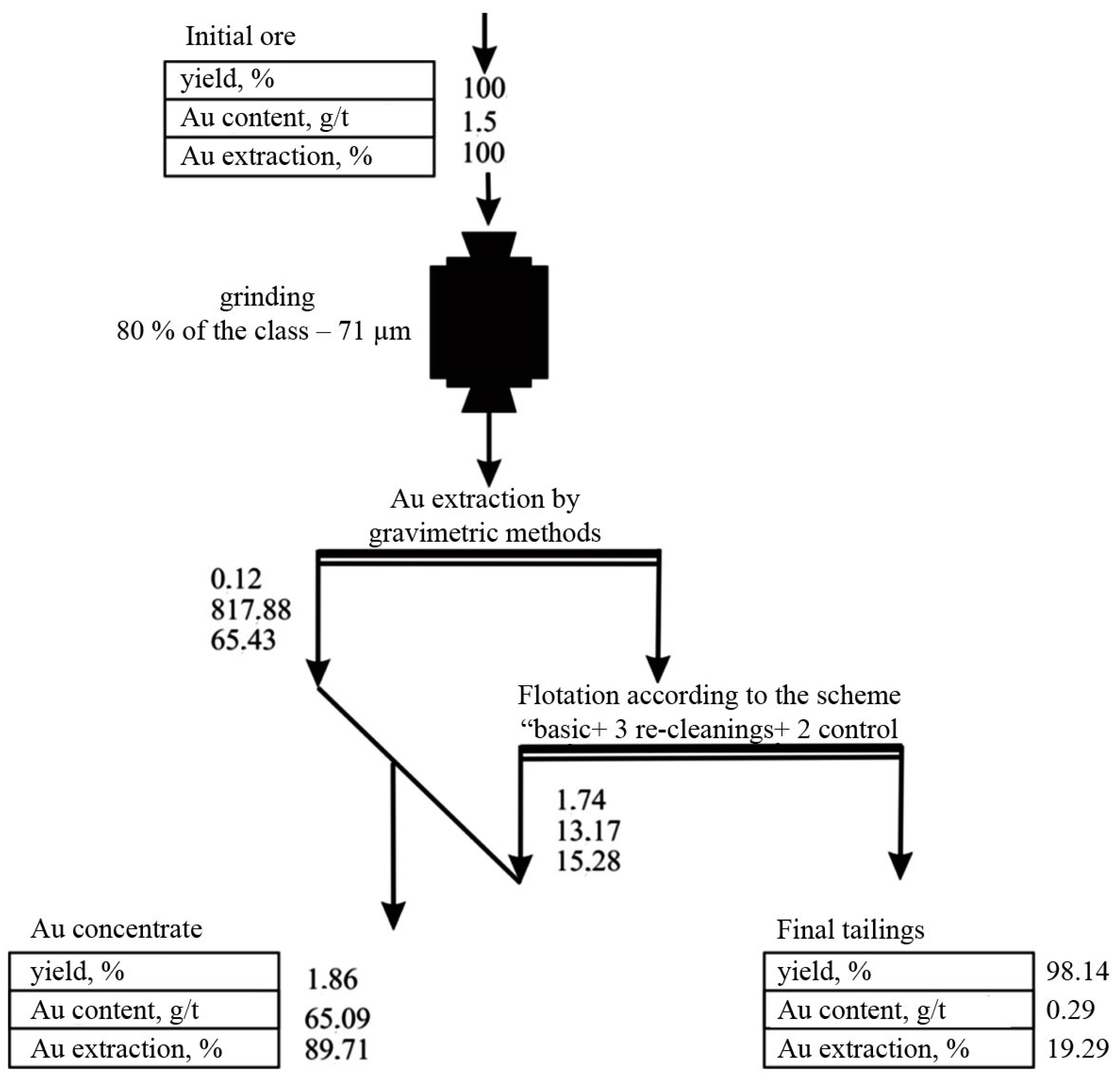
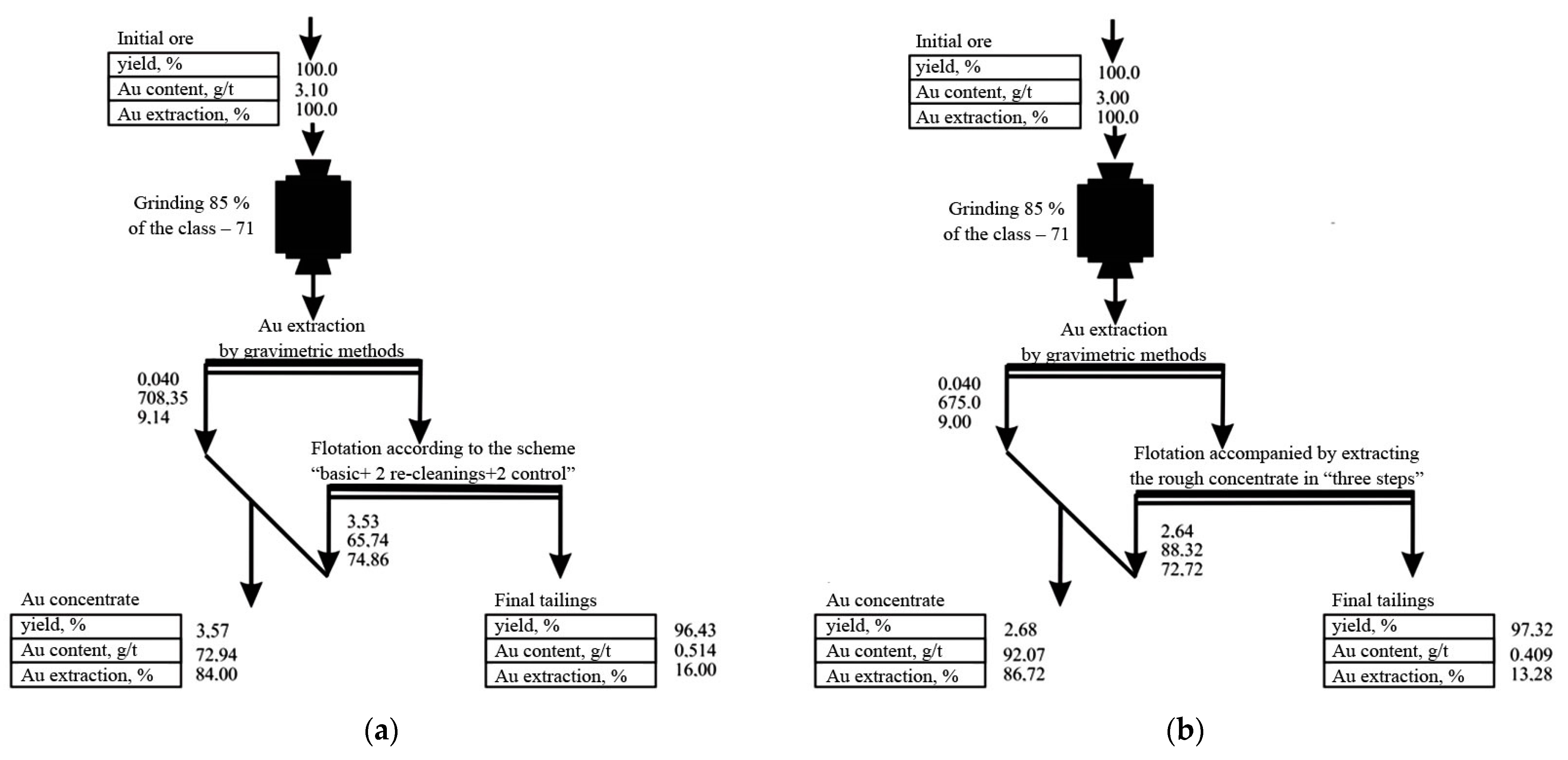
2.1. Flotation of Ores Using the Basic Technology

A schematic block diagram of ore flotation using the basic technology is shown in Figure 1.
Gold was extracted from the ores using a gravity–flotation technology, similar to that adopted at an operating gold extracting factory. An experiment was performed according to a scheme simulating a closed enrichment cycle. A total of 65.43% of Au was extracted into a “golden head” (817.88 g/t of Au) by gravity. Gold was extracted from gravity tailings using a flotation method. The flotation flowsheet included a rougher flotation operation, whose rougher concentrate was recleaned three times; tailings of the rougher flotation operation were subjected to two control flotation operations. In the experiment that simulated a closed flotation cycle, intermediate flotation products (tailings of recleaning and foam products of control flotation operations) were sent from subsequent flotation operations to previous ones. At a rate of 500 g/t, starch was used to suppress organic carbon, which allows a reduction in the carbon content in a concentrate from 6.1 to 1.4% and the extraction from 47.0 to 1.4%. Gold-bearing sulfides were activated with copper sulfate when loading sodium carbonate up to pH 8.5–8.7. Another 15.28% of Au was extracted into a flotation concentrate, using butyl xanthogenate and a foam agent T-92.

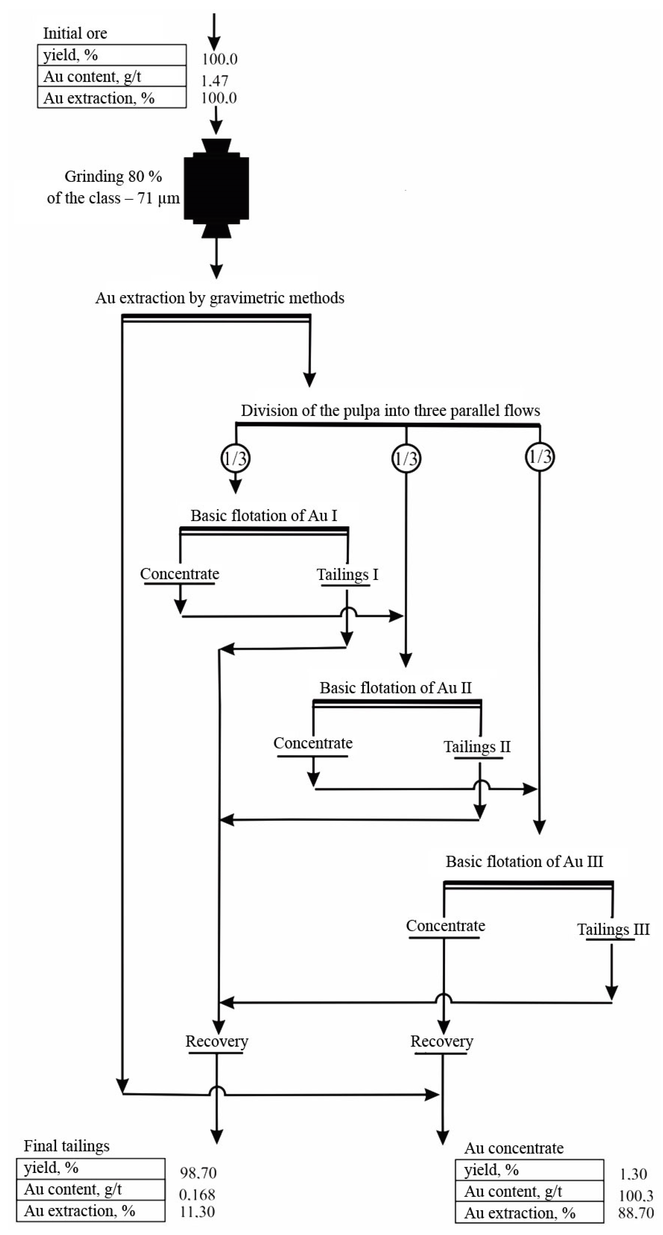
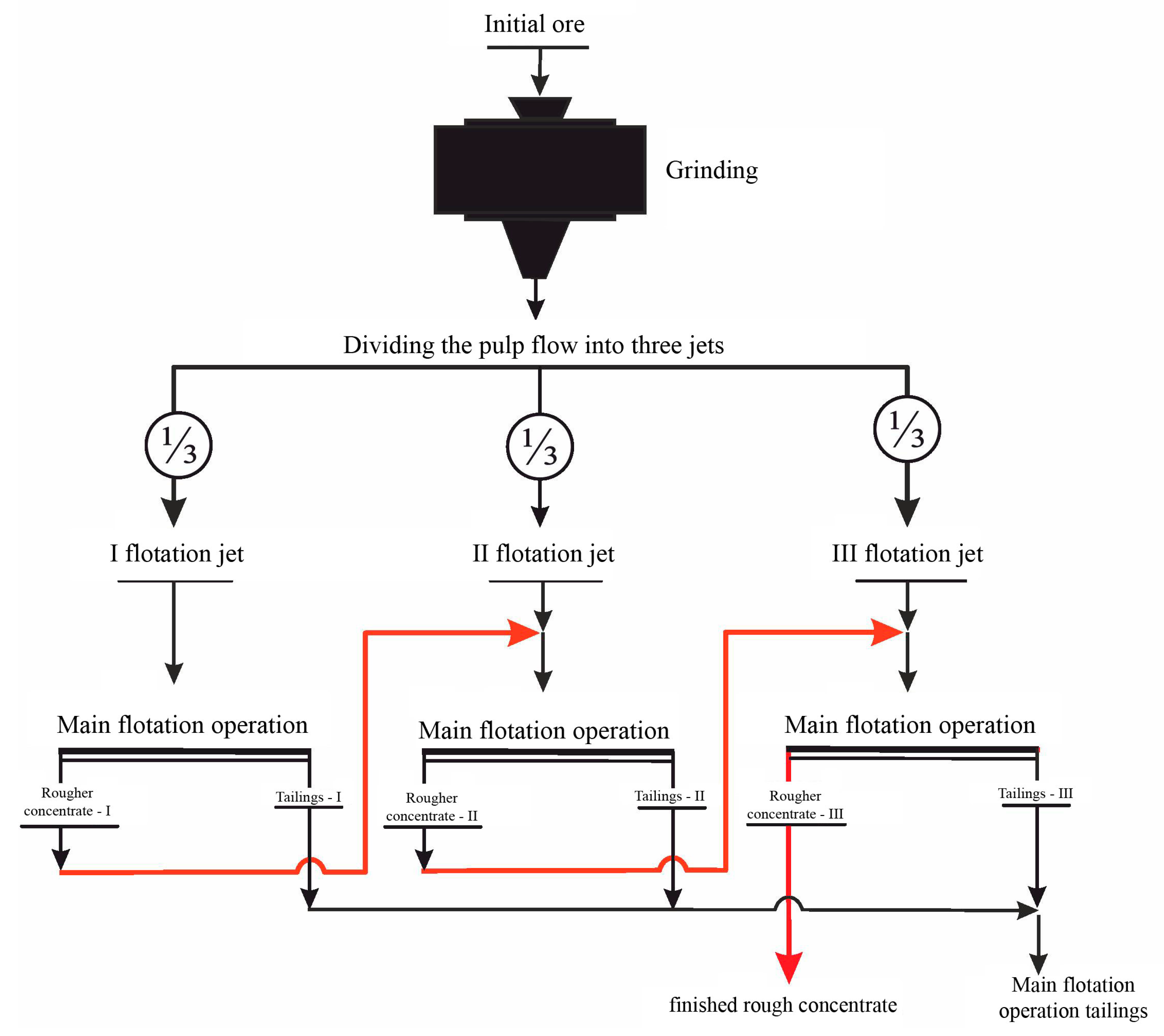
2.2. Flotation of Ores Accompanied by Isolating the Rougher Concentrate in “Three Steps”

Figure 2 shows the results of flotation of ores from the Natalka deposit (a cycle of extracting gold by gravitational methods and a cycle of basic flotation), using the rougher concentrate as carrier minerals to extract gold microdispersions. The results were obtained in the experiment modulating a closed flotation cycle.
A structural and technological scheme of ore flotation (and a reagent mode of mineral separation), using the rougher concentrate as carrier minerals, intended for extracting gold microdispersions, was similar to that used in the basic technology (Section 2.1, Figure 1). The finishing of the rougher concentrate consisted in its three re-cleanings; the finishing of tailings of three main flotation operations consisted of two control flotation operations.

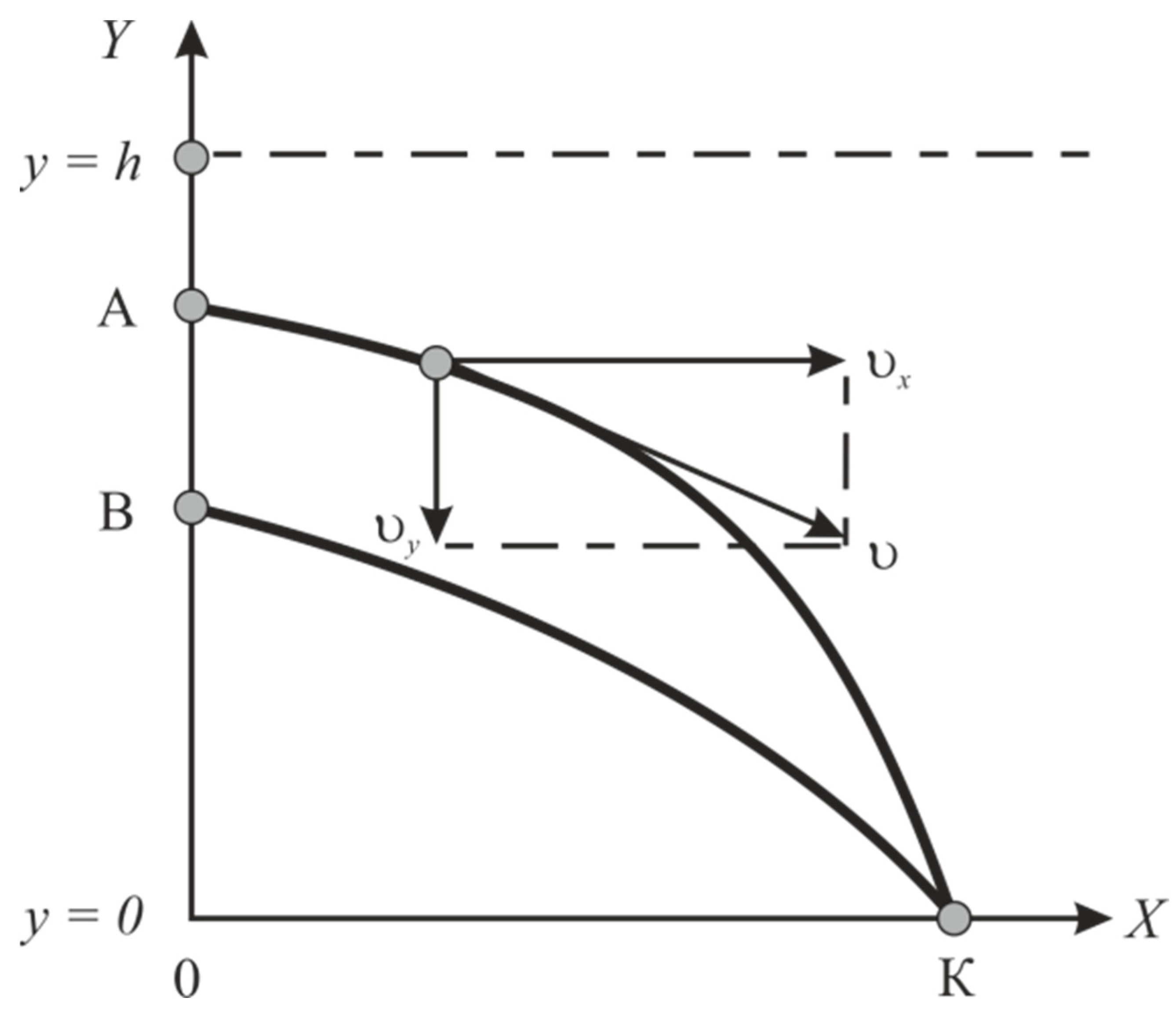
3. Theoretical Provisions

Upon approaching a bubble, large particles collide with a bubble surface, deviating under the action of inertia forces from fluid flow lines, flowing around a bubble. Inertia forces decrease along with the decreasing particle size, which makes it difficult for them to collide with the bubble surface. Therefore, with large particles, a process of flotation complex formation is limited by an adhesion stage, while with fine particles it is limited by their transfer to the bubble surface [41]. Based on peculiarities of the interaction of fine particles with an air bubble, the completeness of extracting fine particles by flotation can be increased by their preliminary aggregation with large particles.
Based on the geometric probability of a collision, we can prove the predominant aggregation of large Ri and fine Rj particles in a polydisperse mineral system.
Polydisperse particles move in a laminar stream along an Ox axis between a surface y = 0 and y = h; a field of external forces is oriented across streams (Figure 3).
According to the diagram (Figure 1), a particle with a size of R j   <   R i begins to move along with a stream at point B having an ordinate:
y B   =   ϕ   ( y h   ,   R i   ,   R j )   =   ψ   ( y h )
Specifying the size of the large particle Ri and an ordinate of its entry into the yA, stream allows for the determination of an AK path and an abscissa of a point of its collision with a wall— x K   =   0   K . This means that particles of an Ri size, when moving along an AK trajectory, can only collide with particles that have crossed an AB segment and have a size of Rj (Rj < Ri).
Provided that particles of j-size are separated from each other by a distance of:
δ j   =   R j c   f   ( R j )   Δ   R j 3
The geometric probability of a collision of polydisperse particles can be determined by the following formula:
p i   j   =   { ( R i   +   R j ) 2 /   δ j 2 w h e n ( R i   +   R j )     δ j     1     w h e n ( R i   +   R j )   >   δ j
where f   ( R j ) —mass differential function of particle size distribution; c—fraction of a large particle surface occupied by fine particles (a density factor of packing fine particles on the large particle surface).
We will divide a segment of 0   y 1 into n   =   h   /   Δ   y parts, and a BK segment will be divided into l   ( k ) parts (where Δ   y   =   δ j , l   ( k )   =   ( y h     y 1 )   /   δ j ).
Then, the geometric probability of a collision of polydisperse particles will be:
p i   j   h   =   1     [ 1     ( R i   +   R j ) 2 /   δ j 2 ]   l   ( h )
If a volumetric unit of a suspension contains C   f   ( R i )   Δ   R i   /   R i 2 particles of i-th size, then the number of particles of the same size crossing a ΔS strip having an area of Δ   S   =   1 δ j per unit time at the entrance is equal to:
Δ   n i | δ j   =   c   Q   δ j   f   ( R i )   Δ   R i   /   ( R i 3   h )
Following [42], the expression for determining the mathematical expectation of the number of collisions of large Ri and fine Rj particles in a suspension of volume V can be written as:
M   ( R i   /   R j )   =   k   =   1 n p i   j   k   Δ   n i   = =     C   V   f   ( R i )   Δ   R i R i 3   h   k   =   1 n { 1     [ 1     ( R i   +   R j δ j )   2 ] l   ( k ) }   δ j
Applying Expressions (4) and (5), as well as taking into account the fact that Δ   y   =   δ j   < <   1   , n   > >   1 , Expression (6) can be rewritten as:
M   ( R i   /   R j )   =   k   =   1 n p i   j   k   Δ   n i   =   =   c   V   f   ( R i )   Δ   R i R i 3   h   k   =   1 n { 1     [ 1     ( R i   +   R j δ j )   2 ] h   Y     ψ   ( h   Y ) δ j   d   Y }
where Y   =   y   /   h .
If R j   <   R i , the mathematical expectation of the number of collisions of particles, whose size is R i     [ R i   ,   R i ] and R i       [ R i   ,   R i ] when Δ   δ i     0 , equals:
M   ( R i   R i     R i |   R j )   =   c   V   i = i i = i f   ( R i ) R i 3   × ×   { 1     0 1 [ 1     ( R i   +   R j δ j )   2 ]   α   d   Y }   Δ   R i
where α   =   h   Y     ϕ   ( h   Y   ,   r   ,   R j ) δ j
As a result, we can find the ratio of the number of collisions of large particles Ri with fine particles Rj to the number of large particles n:
M   ( R i   |   R j )   /   n i   =   1     0 1 { 1     ( R i   +   R j δ j )   2 }   h   Y     ψ   ( h   Y ) δ j   d   Y
Equation (16) allows for the conclusion that particles of the same size moving along the same trajectory practically do not collide with each other. On the contrary, ψ   ( h Y )     0   , ( R i   +   R j ) 2   /   δ j 2   <   1 and a relative collision frequency of large and fine particles is close to 1.
In this work, the effect of a high velocity and the probability of aggregating fine particles with large ones is used to increase the extraction of finely dispersed gold: it is extracted after the preliminary aggregation with carrier minerals. Large particles that act as carrier minerals are intentionally introduced into the pulp. Moreover, as carrier minerals (solid walls), a material as homogeneous as possible with extracted fine particles is used, i.e., a rougher concentrate, which is isolated for this purpose in “three steps” (Figure 4).
For this purpose, the rougher concentrate is isolated from three parallel streams (jets) of the pulp. A rougher concentrate isolated in the first flotation jet is mixed with an initial feed of the second flotation jet; accordingly, the rougher concentrate of the second jet is mixed with an initial feed of the third jet, releasing the finished rougher concentrate.
In this mode of extracting the rougher concentrate, the content of extracted metal increases from jet to jet. Consequently, when using the developed flotation scheme, the achievement of a “synergetic” technological effect is possible due to the aggregation of fine particles with carrier minerals, as well as because of increasing a valuable component content in the basic flotation operation, which contributes to an increase in its extraction.
In order to supplement forces, involved in the separation of minerals by surface forces of structural origin in the third flotation stream, a pulp was aerated during a short time (about 15%–25% of the total) with an air mixture containing hot (≥104 °C) water vapor (steam–air mixture).
It is possible to analyze the relationship between the content of a valuable component α in an initial feed and an amount of its extraction ε.
We can assume that along an enrichment curve ε 0   ( α ) , with a planned content of an extracted metal in an initial ore (equal to α0), a level of achieving its extraction into concentrate (Figure 5) is ε 0   ( α 0 ) . Let us choose other arbitrary values of a metal content in the initial ore α and an operating mode of a flotation unit, at which a metal extraction level along the enrichment curve is ε 0   ( α ) . For the selected mode, an extraction of a metal into a concentrate ε, reduced to α0, will be:
ε   ( α 0 )   = ε   ( α )     ε 0   ( α )   +   ε 0   ( α 0 )
since
ε   ( α )     ε 0   ( α )   =   ε   ( α 0 )     ε 0   ( α 0 )
The value ε   ( α 0 ) does not depend on the position of the curve ε 0   ( α ) in the graph in Figure 5, based on the fact that:
ε   ( α 0 )   = ε   ( α )     ε 1   ( α )   +   ε 1   ( α 0 )
Figure 6 shows the dependence of extracting gold into a concentrate on its content in the initial feed for ores of the Olimpiadinsky deposit, obtained during the study of ores for enrichment.
The results provided in Figure 4 and Figure 5 do not contradict data of other researchers [10] and the practices of the operation of enriching factories [11].
In practice, a necessary increase in the content of an extracted metal in a basic flotation operation is achieved by returning middling products to it, i.e., tailings I of the re-cleaning and the concentrate of the control flotation operation. When the initial feed is mixed with rich middling products, the content of an extracted metal in the basic flotation operation increases. However, a uniformity condition for the separation of the resulting mixture is not fulfilled, because an equality of metal contents in mixed products is not equivalent to their identity in terms of a separation ability. With such a discrepancy, rapidly and slowly floated fractions of extracted and suppressed minerals appear in a flotation cascade. When middling products are mixed with an initial feed, an increase in the metal content in it is achieved mainly via an increase in the concentration of the most difficult-to-float forms of the extracted mineral. A consequence is a decrease in the contrast of a material in terms of flotation properties due to the appearance of extracted minerals of a wide range of floatability. A ratio of flotation rate constants of separated minerals (Beloglazov’s selectivity index) turns out to be close to 1: the flotation rates of a slowly floated fraction of an extracted mineral and a rapidly floated fraction of a suppressed mineral are aligned.
A jet movement of an initial feed and a rougher concentrate ensure a high content of an extracted metal in a basic flotation operation without the appearance of an undesirable distribution of minerals by floatability in the scheme.
Therefore, two possible reasons for increasing the completeness of an extraction of microdispersions of minerals were identified. One reason may be a high rate and a probability of an aggregation of fine minerals with minerals of a rougher concentrate (containing carrier minerals). Another reason may be an increase in the content of an extracted metal in the basic flotation operation when using a rougher concentrate in circulation.
In the general case, the number of parallel streams depends on the content of an extracted metal in ore. Enrichment processes are characterized by a monotonous increase in the extraction of the metal into the concentrate when decreasing the metal content in it. At the same time, when controlling the process, the most important limitation is imposed on the content of the base metal in the concentrate: as a rule, the metal content in the concentrate must correspond to (or exceed) a planned indicator. Based on the limitations imposed on the quality of the concentrate, when determining the number of streams, the goal is to achieve maximum extraction at a given concentration degree in a basic flotation operation.
Isolation of a finished rougher concentrate in the third flotation jet.
Based on the analysis of the density functional of a liquid in a thin gap, the authors demonstrated [42] that a non-uniform decrease in the density of a film thickness led to the appearance of attractive forces, whose magnitude in the case of thin films could significantly exceed van der Waals forces. A distinctive feature of such forces is not a decrease, as was assumed in [43], but the increase in the absolute magnitude of forces when the temperature increases. It also involves a decrease in minimum time required for fixing a particle on the surface of a bubble (induction time) [44] and an increase in the contact angle [45]. Therefore, to complement forces, participating in a separation of minerals, with surface forces characterized by high sensitivity to temperature, it is sufficient to heat a layer of water 4 to 8 nm thick near a bubble, inside which an action of surface forces is localized. In this work, water in the boundary layer of bubbles is heated due to heat of condensation of hot water vapor when a bubble contacts cold water. For this purpose, a pulp was aerated with an air mixture containing hot (≥104 °C) water vapor (steam–air mixture). Steam–air flotation is carried out in a laboratory countercurrent column (Figure 7).
The initial feed is supplied from a mechanical agitator (3) into a column (1) from above under a foam layer (at a distance of ~1/3 of a column height) towards air bubbles generated by a pneumatic atomizer (2) installed in the bottom part of the column. A chamber product is unloaded using an airlift (5), and during emergency unloading it is unloaded through a gate valve (6). There is a system (4) that supplies water to a foam layer (with a secondary concentration of minerals by washing out non-float particles from the foam layer).
The concurrent streams of air and water vapor are created using a steam generator (13) equipped with a steam line and a pneumatic system assembled on the basis of an air blower (7). It is supplied with fine-adjustment valves (8) and a flow meter (9) at an outlet; a pressure gauge (12) with shut-off and control valves (10, 11) is installed in front of the atomizer to control the air pressure. To supply air to an airlift, there is an independent pneumatic system based on a compressor (14) equipped with a flow meter (15), a gas valve (16) and a pressure gauge (17).
A study of the effect of water temperature in boundary layers of bubbles on the results of flotation consisted in analysis of the temperature dependence of the hydrophobic slip and the associated limiting thickness hlim of the interphase film. Physically, hlim corresponds to a limiting distance that a particle can cover to approach a bubble surface under given conditions of their hydrodynamic interaction.
Slipping (inaccurate observance of a boundary condition of the sticking–slipping of a liquid stream over a solid surface) is associated with the presence on a hydrophobic surface of a layer of reduced viscosity (formed due to a stratification of a saturated gas–liquid solution during thinning an interphase gap (Figure 8a) [46,47,48,49]) or microcavities (submicrocavities) containing gas bubbles 10−4–10−2 cm in size retained by surface tension forces (with a rough surface (Figure 8b) [50,51]). Macroscopic slipping on such a surface is a consequence of reduced friction between a liquid and a gas.
The Navier slipping condition (with a zero normal component of a velocity vector un = 0, a tangent component of a velocity us is proportional to a tangent stress τ) is as follows [52]:
u s   =   b e f f   (   u   n )
where beff—apparent slipping length, whose value with a thickness hgl of a wall-mounted gas–liquid layer can be found from the following ratio [53]:
b e f f   =   h g l   ( η l η g l )
During flotation with a steam–air mixture [52,53,54,55], a slip length should be taken into account by a correction kE in the form of:
k E   =   Δ   σ Γ Δ   σ T ,
considering the appearance of tangential stresses associated with the adsorption layer of a surface active agent (SAA):
Δ   σ Γ   =   (   σ   /     Γ )   Γ
and a temperature gradient:
Δ   σ T   =   (   σ   /     T )   Δ   T .
Moreover, a rate of a heat transfer is higher than a rate of a mass transfer (Schmidt number is three orders of magnitude higher than Prandtl number) and when kE < 1, an adsorption convection is completely suppressed by an oncoming Marangoni thermal flow towards a periphery of a wetting film.
When kE~1, there is a dynamic balance between counter-tangential stresses, in which a generated concentration and heat fluxes have approximately the same intensity. Under these conditions, at a tangential velocity of a liquid outflow from an interphase gap of u   ( r ,   z ) , a wetting film is formed, whose limiting thickness hlim is given by an expression in [56,57]. An expression for determining a velocity u in a shear flow of a liquid at a point x, located in a gap of a thickness L (along an Ox axis) between two parallel plates, can be obtained in the form of:
u   =   u S   +   u h g l   x h g l w h e n 0   <   x   <   h gl
u   =   u S   +   u h g l   +   ( Δ   u     2   u h g l )   x     h g l L     2   h g l w h e n h g l   <   x   <   ( L     h g l )
u   =   u S   +   Δ   u   +   u h g l   x     L h g l w h e n ( L   -   h g l )   <   x   <   L
Here, u s   ,   u h g l —velocity of a liquid on a surface of a solid and at a distance of a thickness of a liquid layer hgl with a structure and properties changed compared to volume; Δu—relative velocity of a liquid flow relative to an Oy axis. Consequently:
η g l   u h g l h e f f   =   η l   Δ   u     2   u h e f f L     2   h e f f
and
u h e f f h e f f   =   η l η g l   L     2   h g l   ( η l     η h e f f )   =   η l η g l   Δ   u L   +   2   h e f f   ( η l η g l     1 )
Based on a sticking condition (13), an expression for a slipping length is obtained in the form of (Figure 9):
b e f f   =   h e f f   ( η l η g l     1 ) .
Here, a value heff is given by the following expression:
h eff   =   h g l   ( 1   +   k h )
where kh—dimensionless thickness of an interphase film. A limiting thickness of the film is used as a characteristic value hcr:
k h   =   h lim h cr
The relationship between a limiting thickness of the interphase film hlimb and the time of contact of a particle with a bubble surface is as follows:
t bp   =   R b   /   u b
and relaxation time to a state of a new equilibrium of the film (defined as the time after which a volume of an outflowing liquid differs by no more than 1% from the total volume change during the transition of the film from one equilibrium state to another) [58]:
t rel   =   ( 2   η   R 0 2   h 0 m 2 )   /   m   A     a 2   /   D s
where R0—radius of a curvature of an undisturbed film (meniscus); A—Hamaker constant; m = 1 for a film on a cylinder and m = 2—on a sphere) was obtained in the form of [59]:
h lim   =   γ η   9   π   R 48   a b   t g 2   θ 2   n = 1 1 μ n 2   ( 1   +   1 2   μ n 2   χ )
where
χ   =   t b p t r e l   t K     t Σ | ε   ×   cos   θ e f f   ×   t r e l |   =   t i n d | ε   ×   cos   θ e f f   ×   t r e l |
Here, tc—time of contact of a particle with a surface of a bubble. t Σ   =   b υ Γ   +   b υ T   +   b υ χ —correction for fluid slippage; υ Γ   =   R b   η l 1   (   σ   /     C )   Δ   C —capillary condensation flow rate [56,57,58]; υ T   =   R b   η l 1   (   σ   /     T )   Δ   T —thermocapillary flow rate [60,61,62]; υ χ   =   2   h   χ   R b   T   /   (     T   /     R b ) —thermosmotic flow rate [58]; θeff—effective receding contact angle; ΔT, ΔC—difference in a length of an interphase film of temperature and SAA concentration; tind—induction time; ε—proportion of stuck particles at a given contact time tc.
A value of a contact angle θ ( θ     90   ÷   180 0 ) is determined by the physico-chemical properties of a solid surface, and in a mode of a heterogeneous wetting of a rough Cassie–-Baxter surface, a relationship of an effective receding contact angle θeff with a contact angle determined by a Young equation θ0 is provided by the following ratio [63,64]:
cos   θ e f f   =   f   ( r   ×   cos   θ 0   +   1 )   -   1
where θeff—effective receding contact angle, determined in a wetting mode, when a surface is heterogeneous, composed of areas having a Young’s contact angle θ0 and depressions partially or completely filled with air. f     0   ÷   1 —proportion of a surface area wetted in a homogeneous Wenzel–Deryagin regime; r—coefficient considering a deviation in Young’s contact angle from a contact angle measured on a rough surface. When f→1, the Wenzel–Deryagin regime of the homogeneous wetting corresponding to a boundary minimum of free energy, which replaces a local minimum corresponding to a heterogeneous Cassie–Baxter wetting. Conversely, when f→0, minimum free energy becomes global (less than a boundary one, which leads to decreasing the wettability of a solid surface).

4. Results and Discussion

The results of calculating (in the Maple 2021) the values of limiting thickness hlim of an interphase film with Formula (33) with various flotation factors (Figure 10) are presented.
The fixation of a particle on a bubble surface is possible when a wetting film thickness is h   =   h cr     10 nm, at which the hydrophobic interaction intensity (structural attraction forces) begins to increase, and the hydrophilic interaction (structural repulsion forces) weakens, which, along with the subsequent thinning of the wetting film, changes the sign of a structural component of wedging pressure. Based on this condition, a high probability of a particle deposition on a bubble surface exists only near its upper pole, when a particle trajectory deviates from a vertical axis of a bubble by an insignificant angle θcr θ   <   π / 100   =   θ c r (Figure 10a). When counter flows formed by a pressure drop, created by an inertia force of a particle approaching a bubble, and a Marangoni convection are aligned in an interphase gap, a capture efficiency becomes negligible (Figure 10b).
At low values of a χ << 1 ratio, an intensity of the surface current, caused by shear stress associated with a concentration SAA gradient, is limited by the diffusion process. And during the time of contact of a particle with a bubble surface, it does not have time to significantly influence, as follows from Formula (23), a limiting thickness of a wetting film.
On the contrary, under a condition of χ >> 1, the driving force for reducing the limiting thickness hlim of the wetting film is a flow, caused by surface SAA diffusion and directed from the center to the periphery of the film (Figure 10c).
In laboratory conditions, studies were conducted to assess the efficiency of a technology of flotation enrichment of gold-bearing ores using a rougher concentrate isolated from a part of ore as carrier minerals to increase the extraction of gold microdispersions.
In the first experiment, tests were performed on a sample of ores from the Natalka deposit. Gold was extracted from ores using two technologies. The first basic technology is described in Section 2.1. The second modified technology is described in Section 2.2.
The difference between the basic technology (Section 2.1, Figure 1) and the modified technology (Section 2.2, Figure 2) is that, in a cycle of a basic flotation operation, a rougher concentrate is isolated in “three steps” from three parallel pulp streams: the finished rougher concentrate is obtained through mixing a recycled rougher concentrate twice with an initial feed. Such countercurrent movement of the recycled rougher concentrate and the initial feed is performed for two purposes. Firstly, a material of the recycled rougher concentrate acts as carrier minerals, whose presence allows for the extraction of gold microdispersions by means of the most effective flotation mechanism of inertialess particles, i.e., sticking to a hydrophobic “solid wall” extremely related to them in genesis and physico-chemical properties. In addition, when recycling the rougher concentrate, the extracted metal content in the feed of the basic flotation operation increases, which enables separating the mixture via flotation of a greater technological efficiency. The effects of introducing carrier minerals and increasing the content of an extracted valuable component are complemented by a flotation mode with a steam–air mixture, whose duration is approximately 15%–25% of the flotation time in an operation [62,63,64].
Concentrates obtained in the first two experiments were analyzed for the distribution of gold in them by size classes using sedimentometric analysis (Figure 11).
A comparison of results obtained during flotation of ores from the Natalka deposit, using two competing technologies, allows for the conclusion that one of the factors contributing to an increase in gold extraction (Figure 8 and Figure 9) is an increase in the extraction of small fractions of a gold-bearing material into a concentrate (Figure 10).
Selective enrichment of a feed of a basic flotation operation contributes to a gold extraction increase, which changes the ratio of useful and polluting minerals in a favorable direction: the content of an extracted metal in a concentrate obtained using the newly developed technology was 100.3 g/t versus 65.09 g/t obtained applying the basic technology. When the feed is enriched with a flotation-active rougher concentrate, a load on a surface of air bubbles is increased with an extracted mineral, and their mineralization with rock particles and other minerals decreases. A consequence of a “competition for space” on an air bubble surface is an improvement in the concentrate quality. As a result of improving the concentrate quality, its yield decreased from 1.86 to 1.30%, which enables reducing costs associated with its expensive metallurgical preparation before leaching gold.
Studying the new technology in laboratory conditions was continued on the basis of a sample of sulfide ores from the Olimpiadinsky deposit. As in the previous experiment, indicators obtained during ore flotation performed according to basic (adopted at an operating gold extracting factory) and newly developed technologies were compared (Figure 12).
The basic scheme of ore flotation (Figure 12a) included a flotation cycle of primary ore and a flotation cycle of industrial products. The first cycle consisted of the main flotation operation involving two re-cleanings of an isolated rougher concentrate, as well as two control flotation operations on tailings of a basic flotation operation. Gold reflotation was realized from an industrial product consisting of tailings I of re-cleaning and concentrate I of control flotation.
After optimizing the reagent flotation mode according to the basic scheme, an experiment on six parallel ore charges was conducted on the principle of a continuous process (when a movement direction of intermediate products was adopted in a canonical flotation scheme). The gold content in tailings of five–six ore charges was stabilized (after some growth observed in previous charges), which indicated that a closed cycle mode had been reached. In the control experiment, gold extraction into a concentrate from six ore charges was 84.0% when the concentrate quality was 65.74 g/t of Au.
When switching to the technology of isolating a rougher concentrate in “three steps” (Figure 12b), the increase in gold extraction was 2.72% (the gold content in the tailings decreased from 0.514 to 0.409 g/t) when the concentrate quality increased from 72.94 to 97.07 g/t. An important technological effect of using the new technology is a 24.9% decrease, thus relatively a concentrated yield.
The gold distribution by size classes of concentrates obtained during the experiment was established by sedimentometric and optical–geometric analysis methods (Figure 13).
The results of sedimentometric and optical–geometric analyses of flotation concentrates (Figure 13) allow for the conclusion that the set goal, i.e., to increase the extraction of gold microdispersions, has been achieved.
Improving the efficiency of flotation provides a solution to the problem of rational environmental management, which allows not only a technical and economic effect to be obtained, but also respect for the environment [65].

5. Conclusions

This work is focused on increasing the extraction of microdispersions of minerals by flotation.
Employing the example of flotation of two gold-bearing ores, the possibility of using high velocity and the probability of the sticking of fine particles to large ones to increase the extraction of finely dispersed gold, when introducing carrier minerals into a pulp in the form of a rougher concentrate, has been shown.
Carrier minerals are isolated from three parallel pulp streams, and the initial feed of the subsequent pulp stream is mixed with the rougher (recycled) concentrate isolated from the previous pulp stream. The ready-made rougher concentrate is isolated from the third pulp stream in a mode of flotation with the air mixture, containing hot water vapor, and is sent for recleaning.
During flotation with the vapor–air mixture, the stability of wetting films is determined by the surface flow of the liquid caused by a temperature-dependent surface-tension gradient (and the shear stress associated with it). The influence of such flows on the thinning rate of wetting films has been proposed to be considered in the form of correction to a sliding length of a liquid in a hydrophobic gap. A correction value is expressed in fractions of a critical thickness of a wetting film: at these distances between a particle and a bubble, the influence of surface forces of structural origin begins to manifest itself: forces of hydrophobic attraction and those of hydrophilic repulsion.

Author Contributions

Conceptualization, S.I.E. and A.I.K.; methodology, V.V.K. and A.M.; formal analysis, V.V.K. and A.M.; investigation, V.V.K. and A.M.; data curation, A.V.K. and N.N.B.; writing—original draft preparation, S.I.E., N.S.G. and A.F.P.; writing—review and editing, S.I.E. and A.I.K.; supervision, S.I.E.; project administration, N.S.G. and A.F.P.; visualization—A.V.K. and N.N.B. All authors have read and agreed to the published version of the manuscript.

Funding

This research received no external funding.

Institutional Review Board Statement

Not applicable.

Informed Consent Statement

Not applicable.

Data Availability Statement

The data presented in this study are available from the corresponding authors upon reasonable request.

Conflicts of Interest

The authors declare no conflicts of interest.

References

  1. Ivanik, S.A.; Ilyukhin, D.A. Flotation extraction of elemental sulfur from gold-bearing cakes. J. Min. Inst. 2020, 242, 202–208. [Google Scholar] [CrossRef]
  2. Alexandrova, T.N. Complex and deep processing of mineral raw materials of natural and technogenic origin: State and prospects. J. Min. Inst. 2022, 256, 503–504. [Google Scholar]
  3. Alexandrova, T.N.; Romashev, A.O.; Kuznetsov, V.V. Development of a methodological approach to determining the flotation capacity of thinly impregnated sulfides. Obogashchenie Rud 2020, 2, 9–14. [Google Scholar] [CrossRef]
  4. Mitrofanova, G.V.; Marchevskaya, V.V.; Taran, A.E. Flotation extraction of the titanium concentrate from apatite-nepheline-titanite ores of anomalous zones of Khibiny deposits. J. Min. Inst. 2022, 256, 560–566. [Google Scholar] [CrossRef]
  5. Li, D.; Wang, H.; Li, C.; Liang, Y.; Yan, X.; Zhang, H. Determination and modulation of the typical interactions among dispersed phases relevant to flotation applications: A review. Adv. Colloid Interface Sci. 2021, 288, 102359. [Google Scholar] [CrossRef] [PubMed]
  6. Pan, L.; Jung, S.; Yoon, R.-H. A fundfmental study on the role of collector in the kinetics of bubble-particle interaction. Int. J. Miner. Process. 2012, 106–109, 37–41. [Google Scholar] [CrossRef]
  7. Wang, J.; Yoon, R.-H.; Morris, J. AFM surface force measurements conducted between gold surface treated in xanthate solutions. Int. J. Miner. Process. 2013, 122, 13–21. [Google Scholar] [CrossRef]
  8. Huang, K.; Yoon, R.-H. Surface forces in the thin liquid films (tlfs) of water confined between n-alkane drops and hydrophobic gold surfaces. Langmuir 2019, 35, 15681–15691. [Google Scholar] [CrossRef]
  9. Dziadkowiec, J.; Javadi, S.; Royne, A.; Bratvold, J.E.; Nilsen, O. Surface forces apparatus measurements of interactions between rough and reactive calcite surfaces. Langmuir 2018, 34, 7248–7263. [Google Scholar] [CrossRef]
  10. Abreu, S.B.; Skinner, W.; Addai-Mensah, J.; Zanin, M. The influence of pyriite content on the flotation of chalcopyrite/pyrite mixtures. Miner. Eng. 2014, 55, 87–95. [Google Scholar]
  11. Xie, L.; Wang, J.; Lu, Q.; Hu, W.; Zeng, H. Surface interaction mechanisms in mineral flotation: Fundamentals, measurements, and perpectives. Adv. Colloid Interface Sci. 2021, 295, 102491. [Google Scholar] [CrossRef] [PubMed]
  12. Arriagada, S.; Acuna, C.; Vera, M. New technology to improve the recovery of fine particles in froth flotation based on using hydrophobized glass bubbles. Miner. Eng. 2020, 156, 106364. [Google Scholar] [CrossRef]
  13. Liu, S.; Xie, L.; Liu, G.; Zhang, H.; Zeng, H. Understanding the hetero-aggregation mechanism among sulfide and oxide mineral particles driven by bifuctional surfactants: Intensification flotation of oxide minerals. Miner. Eng. 2021, 169, 106928. [Google Scholar] [CrossRef]
  14. Teisala, H.; Butt, H.J. Hierarchical structures for superhydrophobic and superoleophobic surfaces. Langmuir ACS J. Surf. Colloids 2019, 35, 10689–10703. [Google Scholar] [CrossRef] [PubMed]
  15. Mishchuk, N.A. The model of hydrophobic attraction in the framework of classical DLVO forces. Adv. Colloid Interface Sci. 2011, 168, 149–166. [Google Scholar] [CrossRef] [PubMed]
  16. Christenson, H.K.; Claesson, P.M. Direct measurements of the force between hydrophobic surfaces in water direct measurements of the force between hydrophobic surfaces in water. Adv. Colloid Interface Sci. 2001, 91, 391–436. [Google Scholar] [CrossRef]
  17. Krasowska, M.; Malysa, K. Wetting films in attachment of the colliding bubble. Adv. Colloid Interface Sci. 2007, 134–135, 138–150. [Google Scholar] [CrossRef]
  18. Englert, A.H.; Krasowska, M.; Formasiero, D.; Raiston, J.; Rubio, J. Interaction force between an air bubble and a hydrophilic spherical particle in water, measured by the colloid probe technique. Int. J. Miner. Process. 2009, 92, 121–127. [Google Scholar] [CrossRef]
  19. Nguyen, A.; Nalaskowski, J.; Miuller, J.D.; Butt, H.-J. Attraction between hydrophobic surfaces studied by atomic force microscopy. Int. J. Miner. Process. 2003, 72, 215–225. [Google Scholar] [CrossRef]
  20. Verrelli, D.I.; Koh, P.T.L.; Bruckard, W.J.; Schwarz, M.P. Variations in the induction period for particle–bubble attachment. Miner. Eng. 2012, 36–38, 219–230. [Google Scholar] [CrossRef]
  21. Verrelli, D.I.; Albijanic, B. A comparison of methods for measuring the induction time. Miner. Eng. 2015, 80, 8–13. [Google Scholar] [CrossRef]
  22. Smith, A.M.; Borkovec, M.; Trefalt, G. Forces between solid surfaces in aqueous electrolyte solutions. Adv. Interface Sci. 2020, 275, 102078. [Google Scholar] [CrossRef] [PubMed]
  23. Sedev, R.; Exerowa, D. DLVO and non-DLVO surface forces in foam films from amphiphilic block copolymers. Adv. Colloid Interface Sci. 1999, 83, 111–136. [Google Scholar] [CrossRef]
  24. Pshenin, V.; Zaripova, N.; Zaynetdinov, K. Modeling of the crude oil (or petroleum products) vapor displacement during rail tanks loading. Pet. Sci. Technol. 2019, 37, 2435–2440. [Google Scholar] [CrossRef]
  25. Guo, H.; Kovscek, A.R. Investigation of the effects of ions on short-range non-DLVO forces at the calcite/brine interface and implications for low salinity oil-recovery processes. J. Colloid Interface Sci. 2019, 552, 295–311. [Google Scholar] [CrossRef]
  26. Grasso, D.; Subramaniam, K.; Butkus, M.; Strevett, K.; Bergendahl, J. A review of non-DLVO interactions in environmental colloidal systems. Rev. Environ. Sci. Biotechnol. 2002, 1, 17–38. [Google Scholar] [CrossRef]
  27. Bal, V. Stability characteristics of nanoparticles in a laminar linear shear flow in the presence of DLVO and non-DLVO forces. Langmuir ACS J. Surf. Colloids 2019, 35, 11175–11187. [Google Scholar] [CrossRef]
  28. Sendner, C.; Horinek, D.; Bocquet, L.; Netz, R.R. Interfacial Water at Hydrophobic and Hydrophilic Surfaces: Slip, viscosity, and diffusion. Langmuir 2009, 25, 10768–10781. [Google Scholar] [CrossRef]
  29. Miller, J.D.; Wang, X.; Jin, J.; Shrimali, K. Interfacial water stucture and the wetting of mineral surfaces. Int. J. Miner. Process. 2016, 156, 62–68. [Google Scholar] [CrossRef]
  30. Boinovich, L.B.; Emelyanenko, A.M. Forces due to dynamic structure in thin liquid films. Adv. Colloid Interface Sci. 2002, 96, 37–58. [Google Scholar] [CrossRef]
  31. Gunko, V.M.; Turov, V.V.; Bogatyrev, V.M.; Zarko, V.I.; Chuiko, A.A. Unusual properties of water at hydrophilic/hydrophobic interfaces. Adv. Colloid Interface Sci. 2005, 118, 125–132. [Google Scholar] [CrossRef]
  32. McKee, C.; Walz, J.Y. Interaction forces between colloid particles in a solution of like-charged, adsorbing nanoparticles. J. Colloid Interface Sci. 2012, 365, 72–80. [Google Scholar] [CrossRef] [PubMed]
  33. Feuillebois, F.; Bazant, M.Z.; Vinogradova, O.I. Effective slip over superhydrophobic surfaces in thin channels. Phys. Rev. Lett. 2009, 102, 026001. [Google Scholar] [CrossRef] [PubMed]
  34. Yakubov, G.E.; Butt, H.-J.; Vinogradova, O.I. Interaction forces between hydrophobic surfaces. Attractive jump as an indication of formation of “stable” submicrocavities. J. Phys. Chem. B 2000, 104, 3407–3410. [Google Scholar] [CrossRef]
  35. Ya Malkin, A.; Patlazhan, S.A. Wall slip for complex liquids—Phenomenon and its causes. Adv. Colloid Interface Sci. 2018, 257, 42–57. [Google Scholar] [CrossRef] [PubMed]
  36. Ke, S.; Xiao, W.; Quan, N.; Zhang, L.; Hu, J.; Dong, Y. Formation and stability of bulk nanobubbles in different solutions. Langmuir ACS J. Surf. Colloids 2019, 35, 5250–5256. [Google Scholar] [CrossRef] [PubMed]
  37. Esteso, V.; Carretero-Palacios, S.; Míguez, H.; Thiyam, P.; Parsons, D.F.; Brevik, I.; Boström, M. Trapping of gas bubbles in water at a finite distance below a water-solid interface. Langmuir ACS J. Surf. Colloids 2019, 35, 4218–4223. [Google Scholar] [CrossRef]
  38. Pashkevich, M.A.; Danilov, A.S. Environmental safety and sustainable development. J. Min. Inst. 2023, 260, 153–154. [Google Scholar]
  39. Malyukova, L.S.; Martyushev, N.V.; Tynchenko, V.V.; Kondratiev, V.V.; Bukhtoyarov, V.V.; Konyukhov, V.Y.; Bashmur, K.A.; Panfilova, T.A.; Brigida, V. Circular Mining Wastes Management for Sustainable Production of Camellia sinensis (L.) O. Kuntze. Sustainability 2023, 15, 11671. [Google Scholar] [CrossRef]
  40. Fedotov, P.K.; Senchenko, A.E.; Fedotov, K.V.; Burdonov, A.E. Studies of enrichment of sulfide and oxidized ores of gold deposits of the Aldan shield. J. Min. Inst. 2022, 242, 218. [Google Scholar] [CrossRef]
  41. Yamilev, M.Z.; Azat Masagutov, M.; Nikolaev, A.K.; Pshenin, V.V.; Zaripova, N.A.; Plotnikova, K.I. Modified equations for hydraulic calculation of thermally insulated oil pipelines for the case of a power-law fluid. Sci. Technol. Oil Oil Prod. Pipeline Transp. 2021, 11, 388–395. [Google Scholar] [CrossRef]
  42. Boinovich, L.B. Long-range surface forces and their role in the development of nanotechnology. Adv. Chem. 2007, 76, 510–528. [Google Scholar]
  43. Wang, J.; Yoon, R.-H.; Eriksson, J.C. Excess thermodynamic properties of thin water films confined between hydrophobized gold surfaces. J. Colloid Interface Sci. 2011, 364, 257–263. [Google Scholar] [CrossRef] [PubMed]
  44. Albijanic, B.; Ozdemir, O.; Nguyen, A.V.; Bradshaw, D. A review of induction and attachment times of wetting thin films betweem air bubbles and particles and its relevance in the separation of particles by flotation. Adv. Colloid Interface Sci. 2010, 159, 1–21. [Google Scholar] [CrossRef] [PubMed]
  45. Esipova, N.E.; Rusanov, A.I.; Sobolev, V.D. Temperature dependence of the contact angle of a sessile bubble at the water-silicon interface. Colloid. J. 2020, 82, 569–575. [Google Scholar] [CrossRef]
  46. Semenov, E.V. Calculation of the probability of collision of suspended particles in a suspension stream. Colloid. J. 1981, VXLIII, 912–917. [Google Scholar]
  47. Denisov, E.F.; Yamilev, M.Z.; Tigulev, E.A.; Pshenin, V.V. Analysis of the current level of technologies for determining the location of non-metallic underground services. Neft. Khozyaystvo—Oil Ind. 2022, 2022, 121–125. [Google Scholar] [CrossRef]
  48. Li, C.; Li, D.; Zhang, H. Surface nanobubbles on the hydrophobic surface and their implication to flotation. Int. J. Miner. Metall. Mater. 2022, 29, 1491–1492. [Google Scholar] [CrossRef]
  49. Jadhav, A.; Barigou, M. Bulk nanobubbles or not nanobubbles: That is the question. Langmuir 2020, 36, 1699–1708. [Google Scholar] [CrossRef]
  50. Huang, W.; Huang, J.; Guo, Z.; Liu, W. Icehobic/anti-icing properties of superhydrophobic surfaces. Adv. Colloid Interface Sci. 2022, 304, 102658. [Google Scholar] [CrossRef]
  51. Li, M.; Xing, Y.; Zhu, C.; Liu, Q.; Gui, X. Effect of roughness on wettability and flotability: Based on wetting film drainage between bubbles and solid surface. Int. J. Miner. Sci. Technol. 2022, 32, 1389–1396. [Google Scholar] [CrossRef]
  52. Kondratiev, S.A.; Khamzina, T.A. Assessment of collecting activity of physically sorbed reagents on the example of easily floatable coking coal sludge. J. Min. Inst. 2022, 256, 549–559. [Google Scholar] [CrossRef]
  53. Evdokimov, S.I.; Golikov, N.S.; Zadkov, D.A.; Voitovich, E.V.; Kondratiev, V.V.; Petrovskiy, A.A.; Konyukhov, V.Y.; Gladkikh, V.A. Studying the Flotation of Gold-Bearing Ores Using Carrier Minerals. Minerals 2024, 14, 88. [Google Scholar] [CrossRef]
  54. Evdokimov, S.I.; Panshin, A.M.; Solodenko, A.A. Minerallurgy. In 2 Volumes, V. 2. Advances of Flotation; OOO NPKP “MAVR”: Vladikavkaz, Russia, 2010; 992p. [Google Scholar]
  55. Evdokimov, S.I.; Gerasimenko, T.E. Determination of rational steam consumption during flotation of apatite-nepheline ores with a steam-air mixture. J. Min. Inst. 2022, 256, 567–578. [Google Scholar] [CrossRef]
  56. Vinogradova, O.I. Drainage of a thin liquid film confined between hydrophobic surfaces. Langmuir 1995, 11, 2213. [Google Scholar] [CrossRef]
  57. Andrienko, D.; Dunweg, B.; Vinogradova, O.I. Boundary slip as a result of a prewetting transition. J. Chem. Phys 2003, 119, 13106. [Google Scholar] [CrossRef]
  58. Strateichuk, D.M.; Martyushev, N.V.; Klyuev, R.V.; Gladkikh, V.A.; Kukartsev, V.V.; Tynchenko, Y.A.; Karlina, A.I. Morphological Features of Polycrystalline CdS1−xSex Films Obtained by Screen-Printing Method. Crystals 2023, 13, 825. [Google Scholar] [CrossRef]
  59. Bosikov, I.I.; Martyushev, N.V.; Klyuev, R.V.; Tynchenko, V.S.; Kukartsev, V.A.; Eremeeva, S.V.; Karlina, A.I. Complex Assessment of X-ray Diffraction in Crystals with Face-Centered Silicon Carbide Lattice. Crystals 2023, 13, 528. [Google Scholar] [CrossRef]
  60. Alexandrova, T.N.; O’Connor, C. Processing of platinum group metal ores in Russia and South Africa: Current state and prospects. J. Min. Inst. 2020, 244, 462–473. [Google Scholar] [CrossRef]
  61. Boldyrev, D.V.; Anufrieva, S.D. Approximation of the temperature dependence of the liquid viscosity. Innov. Sci. 2015, 11, 18–20. [Google Scholar]
  62. Alexandrova, T.N.; Elbendari, A.M. Increasing the efficiency of phosphate ore processing using flotation method. J. Min. Inst. 2021, 248, 260–271. [Google Scholar] [CrossRef]
  63. Yelemessov, K.; Baskanbayeva, D.; Martyushev, N.V.; Skeeba, V.Y.; Gozbenko, V.E.; Karlina, A.I. Change in the Properties of Rail Steels during Operation and Reutilization of Rails. Metals 2023, 13, 1043. [Google Scholar] [CrossRef]
  64. Boinovich, L.B.; Emelianenko, A.M. Hydrophobic materials and coatings: Principles of creation, properties and application. Adv. Chem. 2008, 77, 619–638. [Google Scholar]
  65. Antoninova, N.Y.; Sobenin, A.V.; Usmanov, A.I.; Shepel, K.V. Assessment of the possibility of using iron-magnesium production waste for wastewater treatment from heavy metals (Cd2+, Zn2+, Co2+, Cu2+). J. Min. Inst. 2023, 260, 257–265. [Google Scholar] [CrossRef]
Figure 1. Basic block diagram of flotation of ores from the Natalka deposit using the basic technology.
Minerals 14 00108 g001
Figure 2. Basic block diagrams of flotation of ores from the Natalka deposit accompanied by isolating the rougher concentrate in “three steps”.
Minerals 14 00108 g002
Figure 3. Scheme used for calculating the geometric probability of the collision of polydisperse particles.
Minerals 14 00108 g003
Figure 4. The structure of a basic flotation operation under study. Red line—the means of obtaining the finished rough concentrate.
Minerals 14 00108 g004
Figure 5. Enrichment curves for the derivation of Equation (10).
Minerals 14 00108 g005
Figure 6. Extraction of gold into a concentrate as a function of its content in the initial ore of the Olimpiadinsky deposit. The red line—middle line; green line—line of experimental values.
Minerals 14 00108 g006
Figure 7. A laboratory-scale plant of column flotation equipped with an aerator: (a)—general column flotation scheme; (b)—steam and air mixer scheme.
Minerals 14 00108 g007aMinerals 14 00108 g007b
Figure 8. A scheme of the liquid slipping along a wall-mounted gas–liquid layer of reduced viscosity (a) and on a rough surface (b).
Minerals 14 00108 g008
Figure 9. A scheme for the geometric determination of a slipping length b in a shear fluid flow.
Minerals 14 00108 g009
Figure 10. Results of analyzing the dependence of a limiting thickness hlim of an interphase film on flotation factors: the dependence of hliim on a magnitude of correction for stabilization of an interphase film χ (when a crossing angle θ of a particle and a bubble ranges from π/100 to 6π/100 (a) and the crossing angle θ varies from 8π/100 to 10π/100 (b)) and on the crossing angle θ of a particle and a bubble (when changing the value of correction for stabilizing an interphase film χ from 0.01 to 10) (c).
Minerals 14 00108 g010
Figure 11. Histograms and differential functions of the particle size distribution f(Rp) for concentrates obtained from gold-bearing ores of the Natalka deposit using basic (a) and newly developed (b) technologies.
Minerals 14 00108 g011
Figure 12. Basic block diagrams of flotation of ores from the Olimpiadinsky deposit according to the basic technology (a) and that accompanied by a rougher concentrate isolation in “three steps” (b).
Minerals 14 00108 g012
Figure 13. Results of determining dispersity of concentrates isolated by means of basic (a) and newly developed (b) technologies.
Minerals 14 00108 g013
Table 1. Chemical composition of ore samples from the Natalka deposit.
Name of the Element, ComponentContent, %Name of the Element, ComponentContent, %
SiO263.5Fegen.4.17
Al2O314.2Feok2.95
K2O3.27Fes1.22
CaO2.65Sgen.0.84
MgO1.95Ssulph.<0.25
MnO0.12Zn0.0070
P2O50.22Pb0.0018
TiO9.56Cu0.0020
Na2O2.33As0.253
Cgen2.48Sb<0.005
CO2 carb4.55Au1.47
Corg1.24Ag0.60
Table 2. Gold distribution by size classes in the sample of ores from the Natalka deposit.
Size Class, µmGold Distribution, %Size Class, µmGold Distribution, %
0–529.738–711.4
5–919.471–10012.0
9–124.0100–1504.4
12–150.7150–25012.8
15–257.0250–5002.8
25–385.8
Table 3. Distribution of gold by size classes in the sample of ores of the Olimpiadinsky deposit.
Grain-Size Class, µmGold Distribution, %Grain-Size Class, µmGold Distribution, %
3–531.712–159.9
5–929.015–2514.3
9–1215.1
Table 4. Results of a phase analysis of a gold sample of initial ore (when a grinding size of 98% of a class is 74 µm).
Form of Finding GoldNatalka DepositOlimpiadinsky DepositNatalka DepositOlimpiadinsky Deposit
Au Content, g/tAu Distribution, %
Free gold and in accretions, cyaninated1.041.4370.7047.70
Gold associated with sulfides0.280.8619.1528.70
Gold in films and “jackets” of iron hydroxides0.0360.372.4812.40
Gold encased in quartz0.110.347.6711.20
Initial sample1.473.00100.00100.00
Disclaimer/Publisher’s Note: The statements, opinions and data contained in all publications are solely those of the individual author(s) and contributor(s) and not of MDPI and/or the editor(s). MDPI and/or the editor(s) disclaim responsibility for any injury to people or property resulting from any ideas, methods, instructions or products referred to in the content.

