Article

Effect of Potassium Salt on Swelling of Halloysite Clay Mineral during Leaching Process of Ionic Rare Earth Ore

Key Laboratory for Green Chemical Process of Ministry of Education, School of Chemical Engineering and Pharmacy, Wuhan Institute of Technology, Wuhan 430205, China
*
Author to whom correspondence should be addressed.
Minerals 2023, 13(7), 906; https://doi.org/10.3390/min13070906
Submission received: 11 May 2023 / Revised: 29 June 2023 / Accepted: 30 June 2023 / Published: 4 July 2023
(This article belongs to the Special Issue Recent Developments on the Leaching Process of Rare Earth Ore)

Abstract

:
Currently, the primary method for leaching rare earth ores is through in situ leaching. This approach involves contact between clay minerals and liquids, which can lead to the potential swelling of clay minerals with water, triggering natural disasters such as landslides. The main purpose of this study is to select the suitable anti-swelling solution for Hunan Jianghua ionic rare earth ore. According to the ore composition analysis, 88 wt% of Hunan Jianghua ionic rare earth ore is composed of halloysite clay mineral. Therefore, halloysite clay mineral is used to investigate its anti-swelling behavior in order to provide a reference for future research on the selection of raw ore swelling inhibitors. In this study, the traditional leaching agent, MgSO4 solution, was used as the solvent along with two additional compounds, CH3COOK and KCl, which were prepared in different concentrations to form a new composite swelling inhibitor solution to observe their effect on the swelling rate of halloysite clay mineral. At the same time, the seepage velocity of halloysite clay mineral with different anti-swelling solutions is studied. The results indicate that the optimal concentration in the CH3COOK + MgSO4 solution system is 0.05 mol/dm3. At this concentration, the swelling rate is 5.129%, the inhibition rate is 20.08%, and the seepage velocity rate is 12.51 × 10⁻³ cm/min, respectively. In KCl + MgSO4 solution, the swelling rate is 4.868%, the inhibition rate is 24.15% and the seepage velocity rate is 13.23 × 10⁻³ cm/min at the concentration of 0.02 mol/dm3, which is the optimum concentration. In addition, FTIR and TG studies have further demonstrated the mechanism by which these two composite bulking inhibitors inhibit the swelling of halloysite clay mineral.

1. Introduction

The ionic rare earth ore was discovered in Jiangxi Province in 1969 and quickly attracted domestic and international attention due to its abundant medium and heavy rare earth resources [1]. It is named “ionic rare earth ore” because the rare earth ions are mainly adsorbed onto clay minerals in the form of hydrated or hydroxyl hydrated ions.
This special form of adsorption of rare earth ions makes the traditional physical beneficiation methods hard to use to enrich rare earths. Therefore, given the special characteristics of ionic rare earth ores, beneficiation methods have gradually been improved to enrich rare earth by the method of ion exchange [2,3,4]. Based on the ion exchange principle, Chinese scientists and technicians have developed a method of using an aqueous solution of electrolyte as the medium for leaching rare earth ions, which has gradually developed into three different leaching processes. The first-generation leaching process is called the sodium chloride leaching process, and the leaching form also changes from the initial barrel leaching to the later pool leaching. The emergence of this method is due to the availability and low price of sodium chloride as the leaching agent. However, in the later stage, due to the environmentally unfriendly nature of sodium chloride wastewater and the low leaching rate of rare earth ions caused by sodium ion precipitation, this process was gradually replaced [5]. The second-generation leaching process differs from the first-generation leaching process in that ammonium sulfate is used instead of sodium chloride as a leaching agent to leach rare earth. However, it has also been abandoned at a later stage because the pond leaching method requires an extensive approach to mountain deprivation. This process would cause great damage to the mountainous areas and vegetation and seriously disturb the local ecological balance. The third-generation leaching process is called the in-situ leaching process. The leaching agent is injected into the mountain from a manually drilled injection well on the mountain, selectively leaching the whole mountain, and then the leachate is collected through a recovery chamber and sent to a surface plant for subsequent processing [5]. The formation of the third-generation in-situ leaching process effectively solves the shortcomings of the first-generation and the second-generation, which can only be carried rare earth blocks for pool leaching or heap leaching, as well as the low leaching efficiency caused by leaching only a quantitative amount of rare earth ore each time, which greatly saves manpower and material resources. However, new problems also arise during implementation. The in-situ leaching process requires leachate injection from the interior of the mountain, which means that the entire surface or interior of the mountain may be soaked with leachate.
When a clay is surrounded by an aqueous phase, the negative charge on the clay surface will combine with the cations in the aqueous phase material, resulting in hydration. The hydration will form a directional water film on the clay surface, which means that the equilibrium state between the clay minerals and the original subsurface fluid is broken, and the clay mineral will swell and disperse [6]. In particular, the swelling of clay upon encountering an aqueous phase can be broadly divided into two processes: Surface hydration and osmotic hydration. Surface hydration is the first stage of its swelling. In this stage, water molecules enter the crystalline layer of the clay mineral due to positive and negative charges and hydrogen bonding and start to absorb other water molecules, which leads to the pushing apart of the crystalline layer on the surface of the clay mineral. Thus, the clay swelling phenomenon occurs. Then, further swelling of the clay reaches the second stage, osmotic hydration. Osmotic hydration is mainly due to the repulsive effect of the double electric layer, which makes the distance between the crystalline layers on the surface of the clay mineral larger. It is forced by the imbalance of osmotic pressure. When hydration proceeds, the imbalance in osmotic pressure will intensify. The intensified imbalance will, in turn, accelerate hydration. As a result, the volume change of the clay is usually large during this stage [7].
Clay mineral swelling may cause an increasing number of problems, such as the most typical natural disaster of landslides. In the long history of rare earth mining projects, the ore body has been soaked in the leaching solution for a long time. In this case, the hydration swelling of clay mineral leads to the decline of slope stability, which greatly reduces the shear strength of the ore body, resulting in the effect that the anti-sliding force is less than the shear force, which leads to the instability of the slope, and finally evolves into the occurrence of natural disasters, such as landslides [8,9,10].
Halloysite clay mineral is a typical clay mineral which is naturally produced in nature. It is usually 1:1 silicate mineral, and the specific structural form is tetrahedral SiO4 (Si-O layer) distributed on the outer surface, and its inner surface is octahedron AlO6 structure. In extensive research, halloysite clay mineral particles are usually fibrous or tubular structure. In addition, there are many other particle shapes, including spherical, plate-shaped, and prismatic. In previous studies, due to the similar chemical composition of halloysite clay mineral and kaolinite, scholars are always keen to put these two clay minerals together for comparison and discussion. However, by observing the morphological characteristics of these clay minerals, kaolinite presents a hexagonal outline of the plate structure which is different from halloysite clay mineral [11,12]. A large number of researchers have studied various aspects of halloysite clay mineral. Qiu compared the adsorption and desorption characteristics of light and heavy rare earth elements on halloysite clay mineral and illite through experiments and established the relationship between the adsorption/desorption mechanism and mineral properties. The experiment shows that the adsorption rate of halloysite clay mineral is higher than that of illite, and its adsorption/desorption mechanism follows the pseudo second-order kinetic model [13]. Zhou discussed the adsorption/desorption characteristics of Eu (III) on halloysite clay mineral and kaolinite. The results show that the adsorption capacity and retention capacity of halloysite clay mineral are better than kaolinite [14]. The theme of swelling of halloysite clay mineral explored in this manuscript has not been studied similarly after an extensive search, which also indicates the necessity of conducting research on this topic.
In recent years, researchers have conducted much research to improve clay swelling in order to effectively eliminate landslide disasters. Guo configured polyethylene glycol (PEG) with different molecular weights to test its inhibition on clay minerals swelling. The PEG with a molecular weight of 200 exhibited good swelling inhibition, and its mechanism was verified by characterization [15]. Balaban experimentally explored the anti-swelling effect of three compounds on clay minerals, namely quaternary ammonium salt, cationic quaternary ammonium chloride with quaternary ammonium group, and cationic polyacrylamide chloride with quaternary ammonium group mixed with brine containing NaCl and KCl. The experiments proved that the cationic polyacrylamide chloride with the quaternary ammonium group had a better anti-swelling effect, especially when NaCl and KCl salt water were added, the anti-swelling effect is better [16]. Zhang found that the binary system consisting of urea and NH4NO3 had the most significant inhibitory effect on the swelling of clay minerals when the pH was 5. The mass ratio of NH4Cl and NH4NO3 was 7:3, and the mass ratio of urea was 6%-wt [17]. Therefore, to solve the problem of clay minerals swelling, it is particularly important to select a suitable swelling inhibitor to use with the leaching agent.
In this work, the inhibitory effect of CH3COOK and KCl on the swelling rate of halloysite clay mineral in contact with aqueous substances is studied. Halloysite clay mineral is a typical kaolinite group mineral, which in most cases presents tubular morphology. Its chemical formula is Al2Si2O5(OH)4, and its XRD standard card number is 29-1487. The effect of CH3COOK and KCl on the seepage velocity of halloysite clay mineral is discussed subsequently. The experiments are carried out by varying the concentrations of CH3COOK and KCl and mixing them with MgSO4, which is a leaching agent commonly used in the current rare earth mining industry. The effects of the CH3COOK + MgSO4 system and the KCl + MgSO4 system on the swelling inhibition and seepage velocity of halloysite clay mineral are systematically discussed. It is expected that the optimal compound concentration of the CH3COOK + MgSO4 system and the KCl + MgSO4 system can function in a way that reduces the swelling rate of halloysite clay mineral while promoting the seepage velocity. Therefore, the swelling inhibition properties at the optimal concentration were explored, along with its effects on the seepage velocity rate under the same parameter settings. The objective of this experiment is to ensure that the anti-swelling agent effectively reduces the swelling of halloysite clay mineral while increasing their percolation rate. This will effectively improve the stability of mine soils during rare earth mining and reduce the likelihood of landslides after mining.

2. Experiments

2.1. Experimental Material

2.1.1. Samples Preparation

Due to the strong hygroscopicity of halloysite clay mineral, it can absorb water from the air. Therefore, in order to ensure the dryness of halloysite clay mineral as much as possible, the samples to be tested, X-ray diffraction, particle size analysis, scanning electron microscope, and TG analysis samples were subject to 12 h vacuum drying treatment. For the samples for FTIR analysis, the sample marked as raw ores in infrared detection refers to the halloysite clay mineral that was subjected to 12 h vacuum drying, and the remaining three samples refer to the halloysite clay minerals that were subjected to vacuum drying and their corresponding solutions that have been placed together in a centrifuge tube and shaken at room temperature for 72 h. The halloysite clay mineral immersed in the solution was filtered out by vacuum suction filtration, and then the halloysite clay mineral was subjected to 12 h vacuum drying treatment for infrared spectrum analysis. The vacuum drying process involved placing the corresponding sample on a filter paper, placing it as a whole in a vacuum drying oven, setting the drying temperature to 60°, and removing it after 12 h of drying.

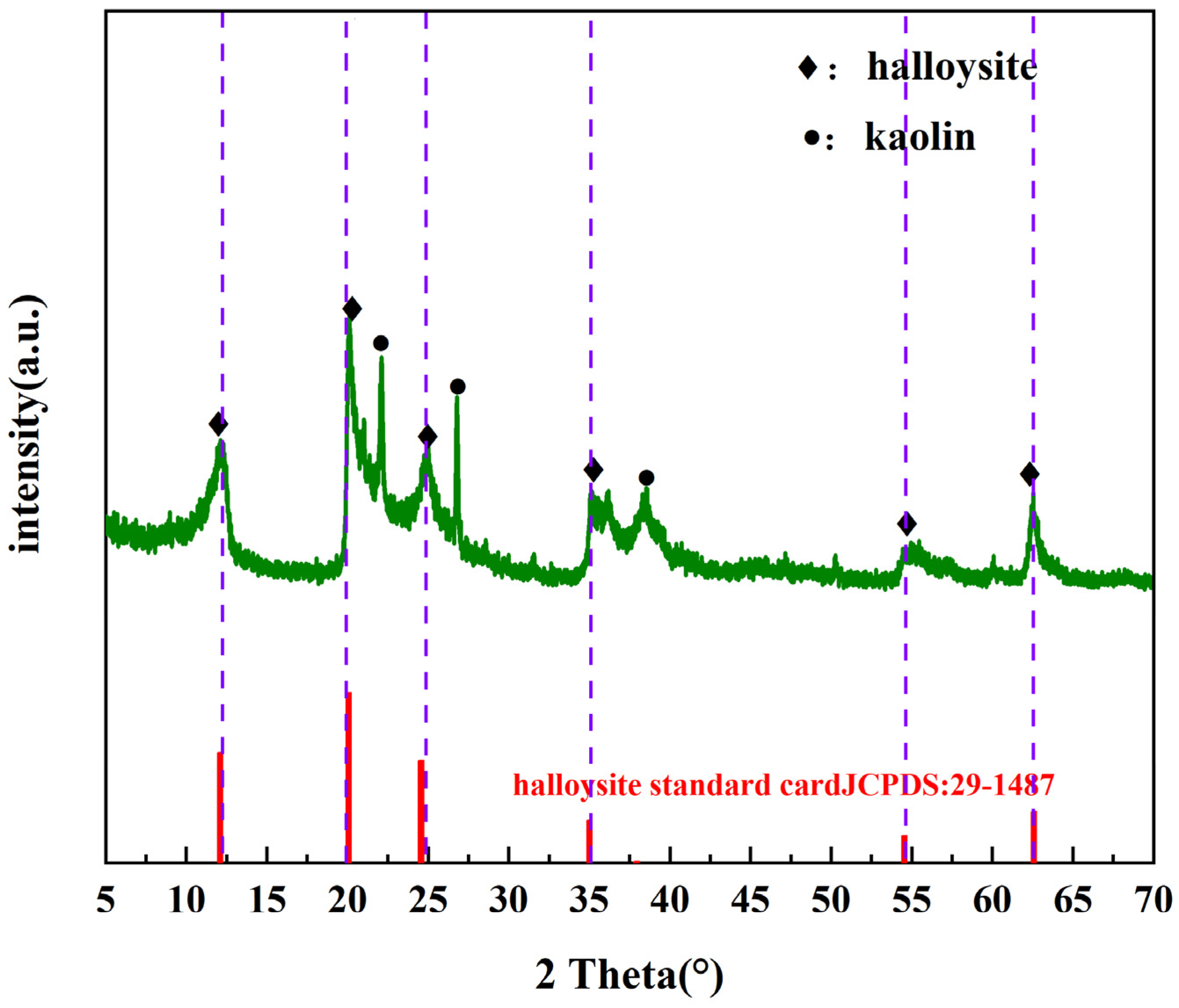
2.1.2. XRD Analysis on Halloysite Clay Mineral

The rare earth minerals selected for this experiment were all from the ionic rare earth mine in Jianghua, Hunan Province. The previous analysis shows that the composition of the clay minerals is 88% halloysite, 10% illite montmorillonite mixture, and 2% illite. Therefore, it is essential to use pure halloysite clay mineral to perform the pre-test study before conducting the original ore experiments, and the pre-test of pure mineral can provide basic data for the study of the real clay minerals from the ionic rare earth mine in Jianghua, Hunan Province.
The halloysite clay mineral used in this experiment was purchased by the supplier. The name of the supplier of our halloysite clay mineral is “Shenzhen Baoan District Fuhai Chuangbo Ceramic Raw Material Factory”. To ensure that the sample selected in this experiment is halloysite clay mineral, X-ray diffraction was performed. Prior to testing, the halloysite clay mineral was processed with room temperature vacuum drying for 12 h. The samples were tested with an X-ray diffractometer. The specific test conditions were Cu target, continuous slow scanning, starting angle of 5°, and ending angle of 90°.
To ensure accuracy, the samples were tested, as shown in Figure 1. Among the peaks formed in both tests, the peaks marked with a diamond shape indicate that they agree with the standard card of halloysite clay mineral below, while a few peaks marked with circular dots represent kaolinite. It can be seen that most of the peaks of the samples in this experiment are consistent with the halloysite clay mineral. Halloysite clay mineral and kaolinite are originally from the same kaolinite family of minerals. The basic structure is kaolinite lamellae interspersed with a layer of water molecules, the structure is similar to kaolinite. Therefore, the halloysite clay mineral is very similar to kaolinite, and the chemical formula shown by the wave peaks of halloysite clay mineral in the XRD test is exactly the same as that of kaolinite, so the wave peaks of kaolinite that appear in a small amount in the XRD pattern of this experimental sample can be included in the error range. Thus, it can be concluded that the samples used in this experiment are indeed a halloysite clay mineral.

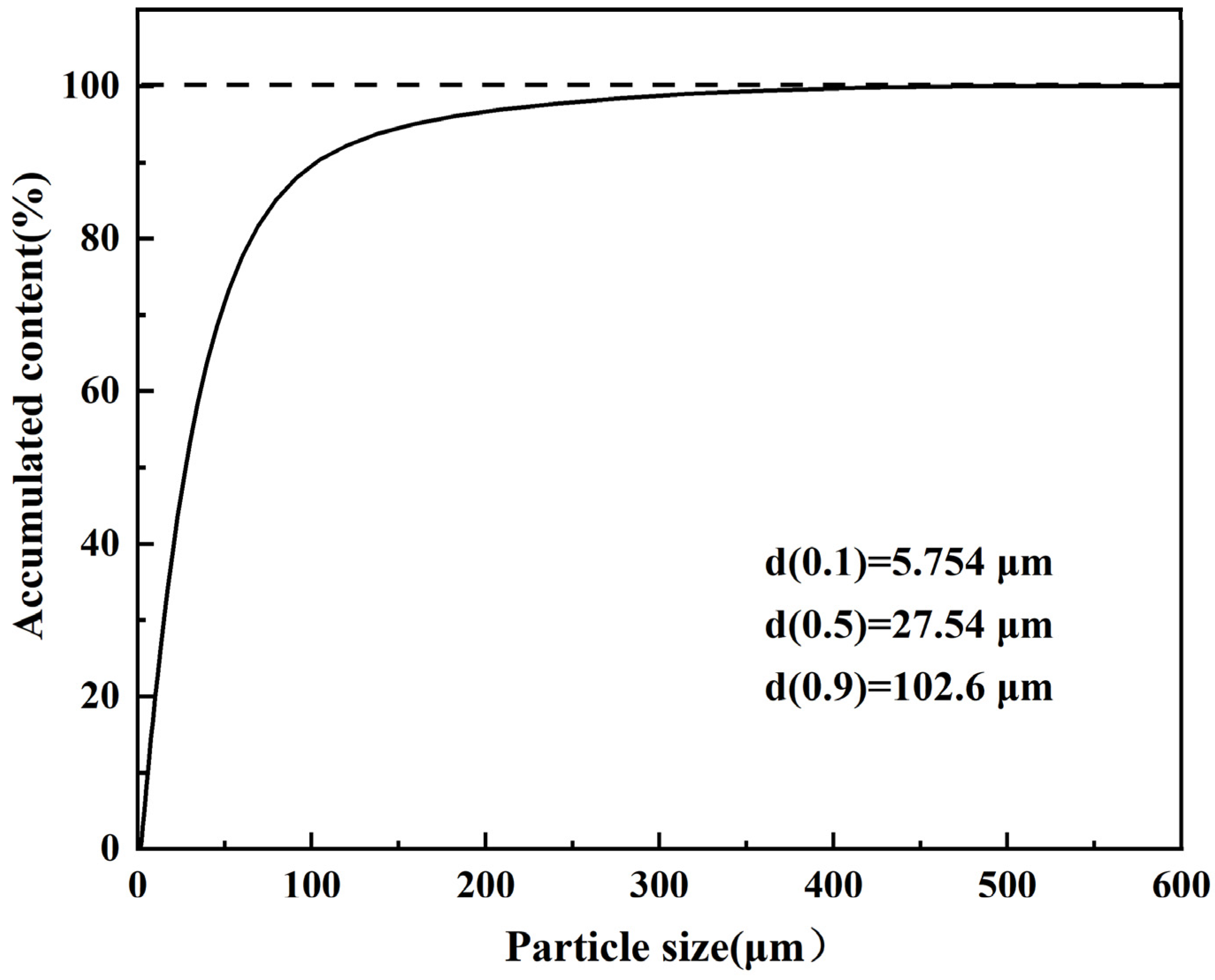
2.1.3. Particle Size of Halloysite Clay Mineral

The particle size detection of halloysite clay mineral is carried out using a laser particle size analyzer, which uses a wet detection method. Two grams of halloysite clay mineral was processed with room temperature vacuum drying for 12 h before particle size analysis and testing, then undergo particle size analysis and testing immediately. The dispersant used in this particle size test experiment is distilled water. It can be seen in Figure 2 that the particle size distribution of this sample is close to normal distribution. Most of the particles are about 100 μm, and their size range is from 5 to 200 μm, which is a small particle size distribution. Due to its more uniform particle size distribution, using this sample can better simulate the ultimate swelling behavior of the real ionic rare earth ore clay minerals, which can minimize experimental errors and obtain more accurate basic data. The particle size range of real rare earth ore samples is 0.15–0.9 mm. Due to the smaller particle size of the selected halloysite clay mineral in this experiment compared to the real rare earth ore sample, it is determined that the swelling rate of the real rare earth ore sample will be lower than that of the halloysite clay mineral in this experiment. Therefore, the particle size tested in this test is only a limit condition, providing basic data for selecting suitable swelling inhibitors for subsequent rare earth mining.

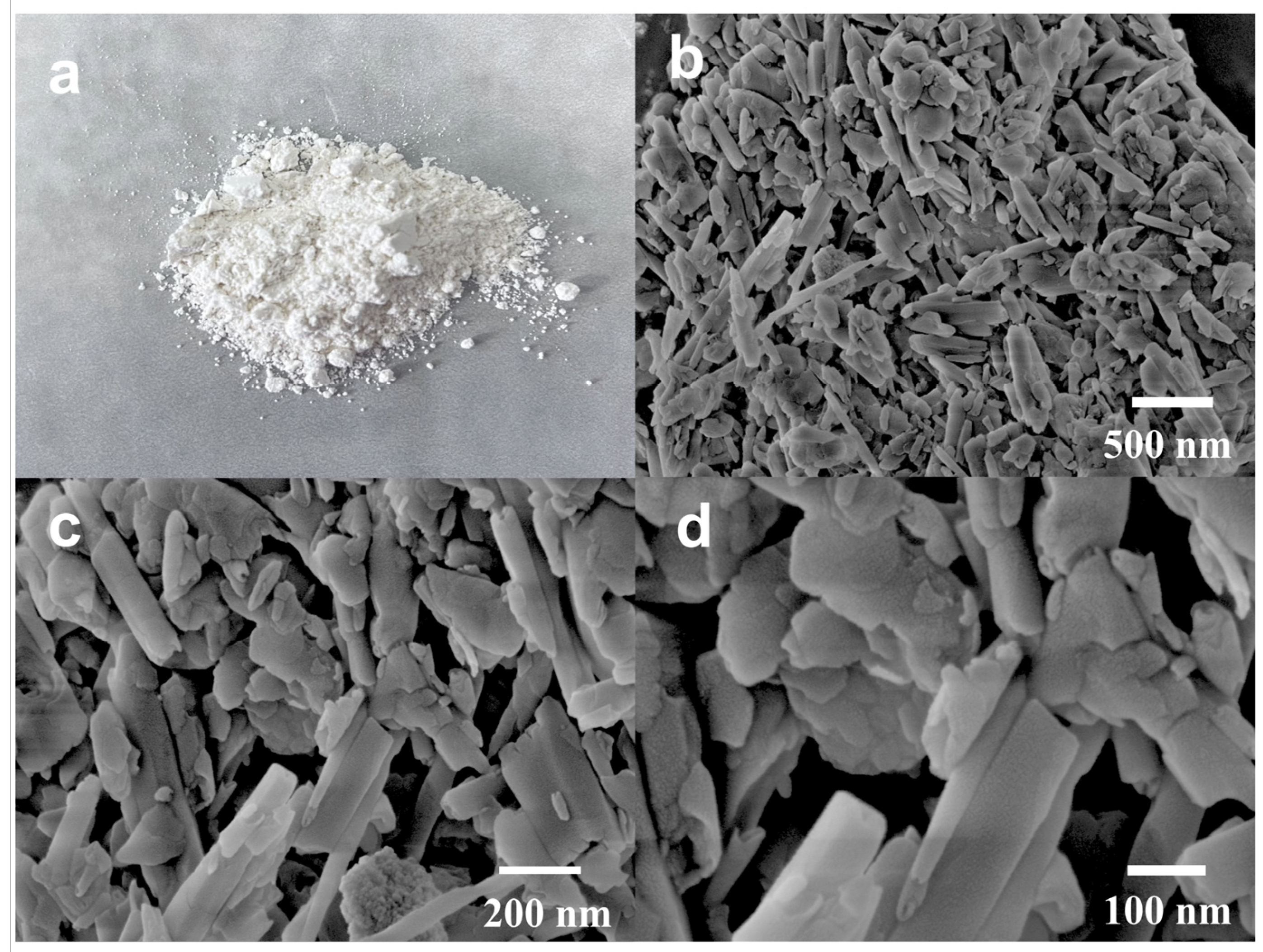
2.1.4. SEM Analysis on Halloysite Clay Mineral

Scanning electron microscopy (SEM) was used to observe the microscopic morphology of halloysite clay mineral. Before conducting scanning electron microscopy testing, the samples of halloysite clay mineral were processed with room temperature vacuum drying for 12 h. The scanning electron microscope test condition for halloysite clay mineral is to use the sample preparation method of directly sticking to the conductive adhesive, without gold spraying, and the test content is a morphology test. The macroscopic photograph of the halloysite clay mineral is shown in Figure 3a. It can be seen that the sample of halloysite clay mineral itself is a white powder. SEM photos of the halloysite clay mineral are shown in Figure 3b–d. They clearly show that the halloysite clay mineral exhibits a tubular structure. In previous studies, in addition to the tubular structure, some of the halloysite clay mineral show various morphologies such as spherical, plate, and prismatic. In this experiment, the selected halloysite clay mineral presents a tubular structure [11,12]. The tubular structure is due to the presence of water molecules between the halloysite particles, which reduce the forces between the halloysite flakes. The bending tendency between the flakes cannot be withstood by the weak hydrogen bonding connection of water molecules, resulting in the tubular structure. Hydrogen bonds may break in solution due to their weak bonding, causing the clay particles to develop the ability to absorb water molecules and resulting in the swelling of clay mineral [18,19].

2.2. Experimental Method

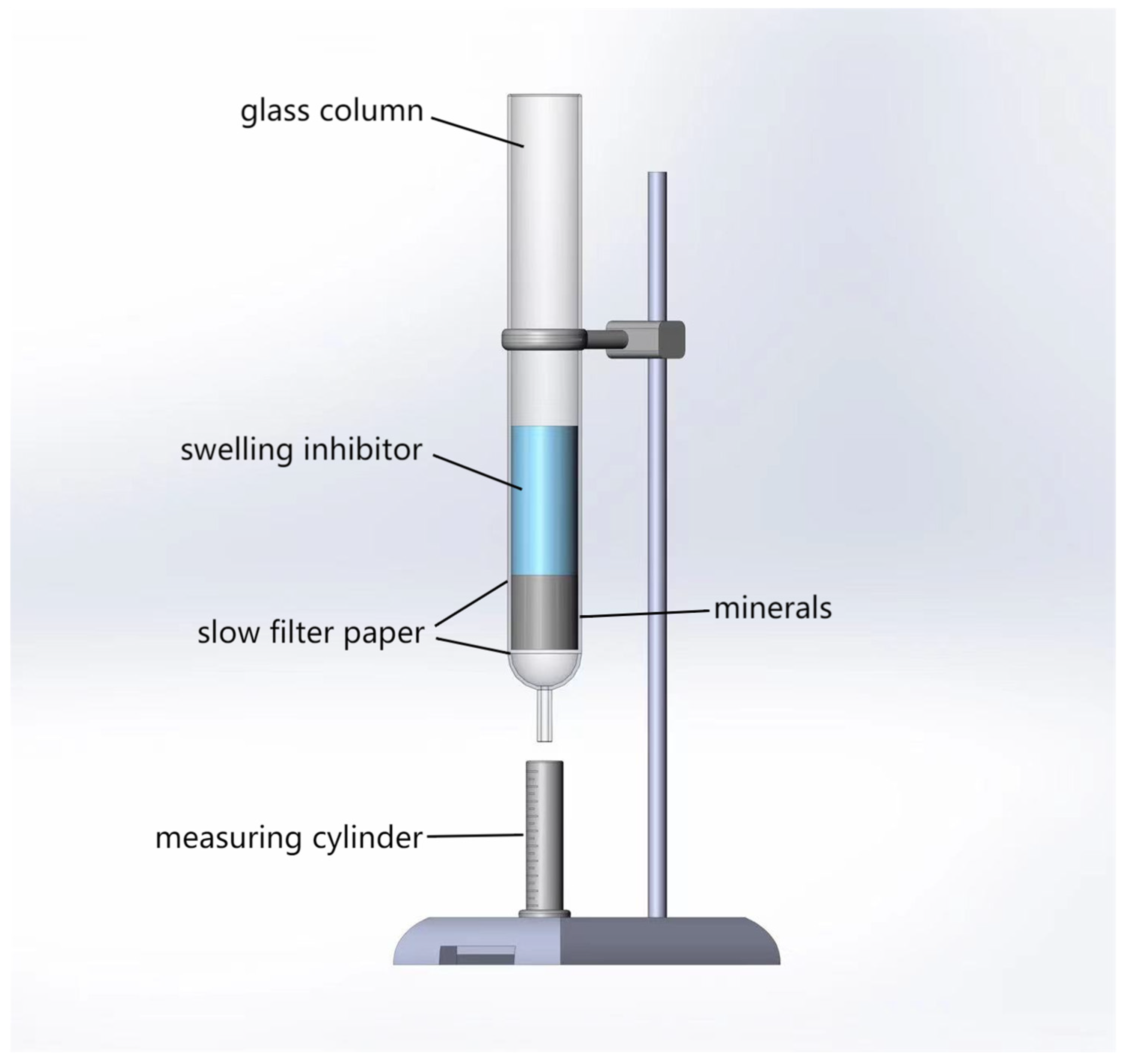
2.2.1. Measurement of Halloysite Clay Mineral Swelling

Samples in this experiment were all processed with room temperature vacuum drying for 12 h. The main device is a modified measuring device for the hydration swelling rate of halloysite clay mineral as described in patent CN202222689435.4 (under application), and the schematic diagram is shown in Figure 4. In Figure 4, the instruments from left to right are the nanovoltmeter, regulated power supply, computer and its display, and sensor test unit, respectively.
The experimental procedure is as follows: 20 g of halloysite clay mineral was weighed, and the weighed halloysite clay mineral was placed into a special mold. After 20 g of halloysite clay mineral is loaded into a specific cylindrical mold, a cylindrical steel column with the same diameter as the mold opening is placed on the surface of the halloysite clay mineral, and then placed on a hydraulic press. The hydraulic press sets a pressure of 1 MPa for 10 min to compact the halloysite clay mineral in the mold through a cylindrical steel column. The halloysite clay mineral and molds were immersed in a solution filled with bulking inhibitor, and the height change of the halloysite column was measured in real-time by a laser rangefinder. The hydration swelling rate of the halloysite clay mineral is calculated by the following equation.
δ = H H 0 × 100 %
wherein, δ refers to the hydration swelling rate, ∆H refers to the height of the change of the halloysite column, and H0 refers to the initial height when the halloysite column is not immersed.
In the actual in-situ leaching mining process, the leaching solution flows through the ore body for 24–48 h, so 72 h was selected as the experimental time for this swelling experiment to study its swelling behavior in order to pursue more accurate experimental data.
For the swelling experiment, three repeated experiments were conducted, and the average of the three experimental results was taken as the final result. At the same time, the corresponding error bars were calculated using the three experimental results and added to the corresponding figures.

2.2.2. Seepage Velocity of Halloysite Clay Mineral in Simulated Column

Column leaching experiment was used to simulate the in-situ leaching process of ionic rare earth ores. Two layers of quantitative slow filter paper were placed on the sand core at the bottom of the glass column, and 20 g of dried halloysite clay mineral was weighed and uniformly loaded into the glass column. The mineral loading process should follow the principle of small quantities to ensure a uniform distribution of the halloysite clay mineral in the column. A layer of filter paper should be placed over the mineral to ensure the uniform penetration of the swelling inhibitor. Different anti-swelling agents were delivered to the top of the halloysite clay mineral to form a stable liquid column above, to maintain a stable liquid tower height of h by manually adding liquid using a rubber-tipped dropper. The swelling inhibitor percolated through the halloysite clay mineral to the bottom and then exited from the bottom of the glass column. A measuring cylinder was used to collect the leachate, and the interval time and the volume of the collected liquid were recorded. The experimental setup is shown in Figure 5. This experiment was carried out at room temperature.
The seepage velocity rate is:
v = Q A
where, Q is the seepage flow rate, mL/s (calculated according to the time and the volume of leachate collection), A is the cross-sectional area, cm2 (the cross-section of the column).

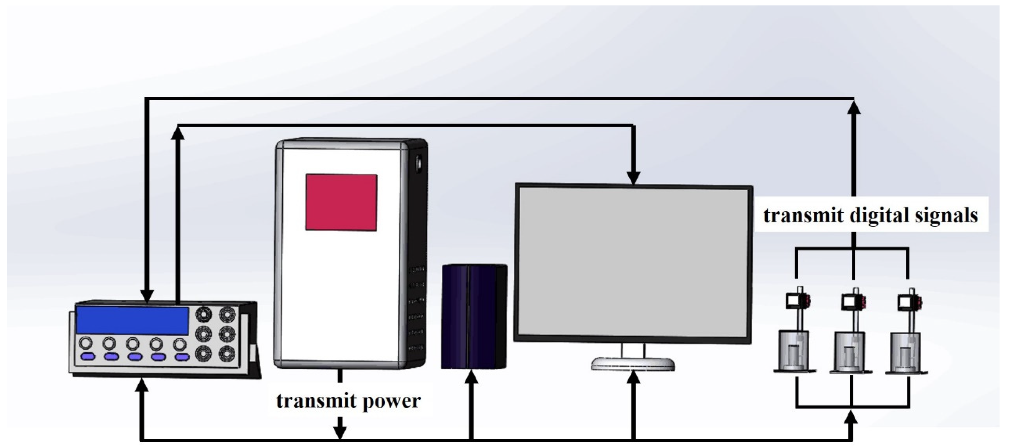
2.3. Experimental Instruments

Main experimental instruments: Homemade clay mineral swelling rate testing device consisting of the nanovoltmeter (IEEE-488), regulated power supply (JJW3-1000VA, Shanghai Zhengxi Electric Co., Shanghai, China), computer, and its display and sensor testing device (BL-100NMZ, BOJKE, dongwan in Guangdong province, Shenzhen, China), hydraulic press (MJTY(MSY)), immersion glass column with an inner diameter of 30 mm, laser particle size meter (Malvern Mastersizer 2000, Malvern, UK), Fourier infrared spectrometer (Thermo Scientific Nicolet iS20, Waltham, MA, USA), scanning electron microscope (ZEISS Sigma 300, St. Louis, MO, USA), thermogravimetric analyzer (TA TGA 550), X-ray diffractometer (Rigaku SmartLab SE, Tokyo, Japan).

3. Results and Discussions

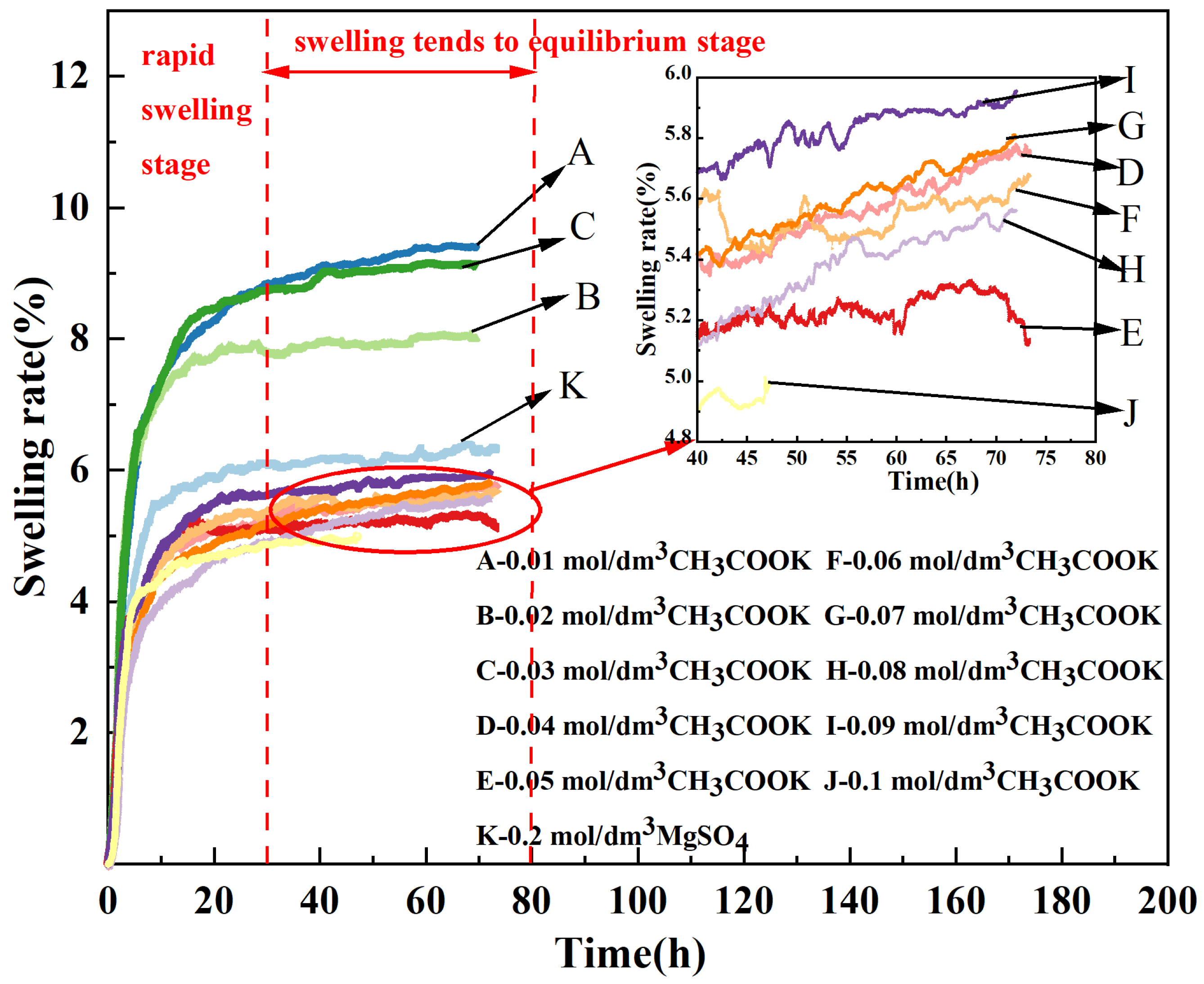
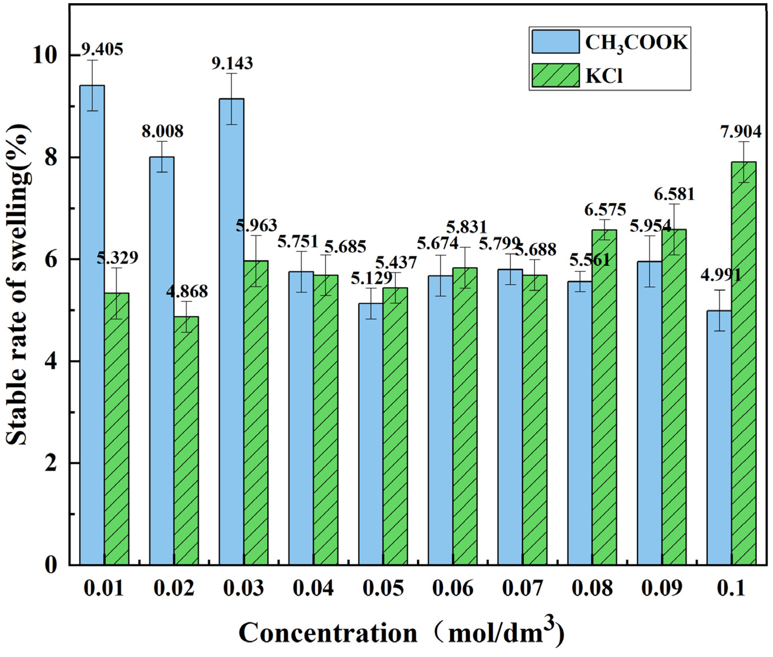
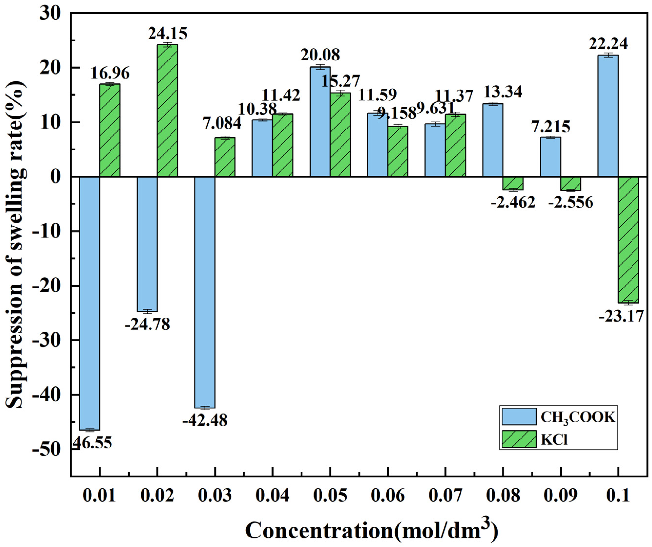
3.1. Effect of Electrolyte Concentration on Swelling Rate of Halloysite Clay Mineral

3.1.1. Effect of MgSO4 Concentration on Swelling Rate of Halloysite Clay Mineral

Before adding anti-swelling agents, it is necessary to explore the swelling rate of halloysite clay mineral at various concentrations of fixed leaching agent MgSO4. In this experiment, six concentrations (0.05, 0.1, 0.15, 0.2, 0.25, and 0.3 mol/dm3) were selected for the swelling rate measurement. At the same time, distilled water was also used to measure its swelling rate. The swelling rate of halloysite clay mineral with different MgSO4 concentrations over time is shown in Figure 6.
It can be seen from Figure 6 that the swelling of halloysite clay mineral in MgSO4 solution reached equilibrium in about 20 h and the swelling rate curve stabilized. The swelling rate of halloysite clay mineral in distilled water was 5.089%. In Figure 6, with the increase of MgSO4 concentration, the stable swelling rate of halloysite clay mineral shows a gradual increase. However, as a leaching agent, MgSO4 should prioritize its leaching capacity. Previous studies showed that the best leaching effect was achieved when the concentration of MgSO4 solution was 2%, and later the concentration was optimized to 0.2 mol/dm3 [19]. Thus, as shown in Figure 6, the stable swelling of the halloysite clay mineral at 0.2 mol/dm3 concentration is 6.417%, which is higher than that of the lower-concentration solutions. Therefore, if only MgSO4 leaching is used to leach the mine, such a high swelling rate of halloysite clay mineral could potentially lead to water and soil loss, landslides, and other risk disasters to subsequent mines. From this view, it is essential to improve the swelling of halloysite clay mineral and ensure the leaching rate of its solution by adding a mixture of swelling inhibitors and leaching agents.

3.1.2. Effect of CH3COOK Concentration on Swelling Rate of Halloysite Clay Mineral

After selecting a suitable concentration of leaching agent MgSO4 solution, complex CH3COOK solutions with different concentrations from 0.01 to 0.1 mol/dm3 were prepared using 0.2 mol/dm3 MgSO4 as the solvent. The swelling rate of halloysite clay mineral was determined by using this solution as a swelling inhibitor. The variation of swelling rate with the time of the halloysite clay mineral at different concentrations of CH3COOK mixed with a leaching agent is shown in Figure 7. The swelling rate of the halloysite clay mineral usually takes a longer time to reach equilibrium in low concentrations than in high concentrations of CH3COOK. Figure 8 shows the comparison of the equilibrium swelling rate of halloysite clay mineral after the stabilization of the swelling rate at different concentrations of the complex CH3COOK solution. The final stabilized swelling rate is 0.01 mol/dm3 > 0.03 mol/dm3 > 0.02 mol/dm3 > 0.09 mol/dm3 > 0.07 mol/dm3 > 0.04 mol/dm3 > 0.06 mol/dm3 > 0.08 mol/dm3 > 0.05 mol/dm3 > 0.1 mol/dm3.
From former experiments, the stable swelling rate of 0.2 mol/dm3 MgSO4 solution is measured to be 6.417%, so the relative swelling inhibition rate after adding CH3COOK is ∈ which is calculated as follows:
= δ 0 δ 1 δ 0 × 100 %
In this formula, δ0 is the equilibrium swelling rate of halloysite clay mineral when using MgSO4 solution with a concentration of 0.2 mol/dm3 as the only leaching agent, %, δ1 is the equilibrium swelling rate of halloysite clay mineral after mixing the swelling inhibitor with MgSO4 solution with a concentration of 0.2 mol/dm3, %.
Figure 9 shows the relative swelling inhibition rate of halloysite clay mineral compared to a single MgSO4 solution after mixing CH3COOK with MgSO4 solution of different concentrations. It can be seen from Figure 9 that CH3COOK with different concentrations has different anti-swelling effects. The small concentration of CH3COOK can promote the swelling of halloysite clay mineral. It can be seen from Figure 9 that CH3COOK with concentrations of 0.1 mol/dm3 and 0.05 mol/dm3 has a better swelling inhibition effect on halloysite clay mineral compared to other concentrations. For the two concentrations of 0.05 mol/dm3 and 0.1 mol/dm3, their anti-swelling effect on halloysite clay mineral is relatively similar. However, for the actual mining process, the amount of leaching agent and swelling inhibitor is huge. Choosing 0.05 mol/dm3 compared to 0.1 mol/dm3 can save a lot of swelling inhibitor usage, which is very beneficial for reducing engineering costs, it is appropriate to select the 0.05 mol/dm3 concentration as the optimal concentration of CH3COOK for cost considerations. The swelling rate at the optimum condition is 5.129%, while the relative swelling inhibition rate is 20.08%.

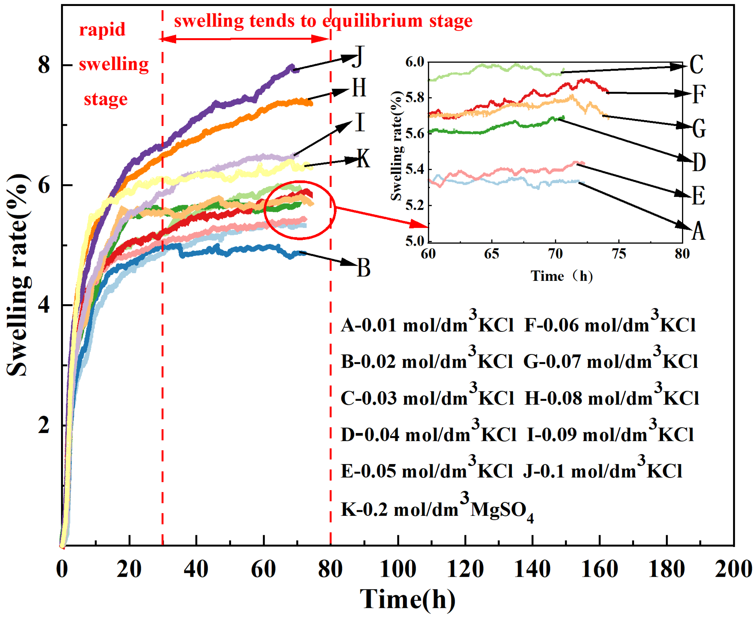
3.1.3. Effect of KCl Concentration on Swelling Rate of Halloysite Clay Mineral

In the above experiments, 10 concentration gradients of KCl (from 0.01 to 0.1 mol/dm3) as the swelling inhibitor were prepared using 0.2 mol/dm3 MgSO4 solution as the solvent to test the swelling rate of the halloysite clay mineral. The variation of the swelling rate of the halloysite clay mineral versus time with different concentrations of the swelling-inhibiting solutions is shown in Figure 10. The halloysite clay mineral takes a longer time to reach a stable swelling rate in the KCl system than in the CH3COOK system compared to Figure 7. Meanwhile, Figure 8 shows the comparison of the swelling rates of the halloysite clay mineral when stabilized at different concentrations of the complex KCl solution. In KCl system, the general trend is that the higher the inhibitor concentration, the higher the swelling rate, and therefore the less effective their swelling inhibition. The swelling suppression effect of KCl on the halloysite clay mineral compared to the single leaching agent MgSO4 solution is shown in Figure 9. In contrast to the CH3COOK system, the lower KCl concentration, the better the anti-swelling effect, while the higher KCl concentration promotes swelling. Among the ten concentrations in the experiment, the concentration of 0.02 mol/dm3 has the best anti-swelling effect, with a swelling rate of 4.868% and a swelling inhibition rate of 24.15%. The good anti-swelling effect of the two swelling inhibitors can be attributed to the K+ ions. The surface of halloysite clay mineral is a tetrahedral structure formed by Si-O [17,18,19,20,21].
Due to the low hydration energy of K+ ions, it is easier for K+ ions to enter the molecular layer of halloysite clay mineral than water molecules. Therefore, K+ ions can easily squeeze water molecules out of the pores of Si-O tetrahedron structure. The entry of K+ ions effectively shields the negative charge on the surface of halloysite clay mineral and prevents the H+ ions in the solution from approaching and hydrating with them, thus achieving the effect of anti-swelling. This phenomenon is also known as the inherent “hydrophobic type” of K+ ions. At the same time, the radius of K+ ions are much smaller than the distance between halloysite clay mineral particles. Therefore, the entry of K+ ions actually leads to a reduction in the volume of halloysite clay mineral, which in turn acts to inhibit the swelling of halloysite clay mineral [21,22,23,24,25].
CH3COOK can be regarded as a surfactant. As a surfactant, CH3COOK can reduce the surface tension of the solid and liquid interface, and the CH3COO ions can be adsorbed on the surface of the clay mineral of halloysite to prevent further hydration and swelling, thus achieving the effect of swelling inhibition [26]. From the above figures, it can be seen that the concentrations of CH3COOK solution and KCl solution have different effects on the swelling rate of the halloysite. The inhibition of swelling of halloysite clay mineral by the CH3COOK solution is a better at higher concentrations, while the KCl solution presents better anti-swelling effect at lower concentrations. This is mainly determined by their different anions. Since CH3COO ions undergo a certain degree of hydrolysis in water and Cl ions carry more negative charge than CH3COO ions, the more negatively charged Cl ions have a stronger attraction to K+ ions, which results in fewer K+ ions entering the surface of halloysite clay mineral and inhibiting swelling. Therefore, the swelling inhibition effect of KCl solutions at lower concentrations is greater. On the other hand, as a surfactant, CH3COOK itself has the effect of swelling inhibition, so a higher concentration of CH3COOK has a better anti-swelling effect [27].
In the early stage of rare earth mining work, ammonium sulfate solution was used as the leaching solution to extract rare earth minerals, but a large amount of ammonium ion solution can cause serious ammonia nitrogen pollution to the land. For this reason, magnesium sulfate solution was later used instead of ammonium sulfate solution as the leaching solution for mining and leaching rare earth minerals. Since then, magnesium sulfate solution has been widely used as a leaching solution. Therefore, the effect of SO42− ions on swelling will not be discussed in this manuscript.

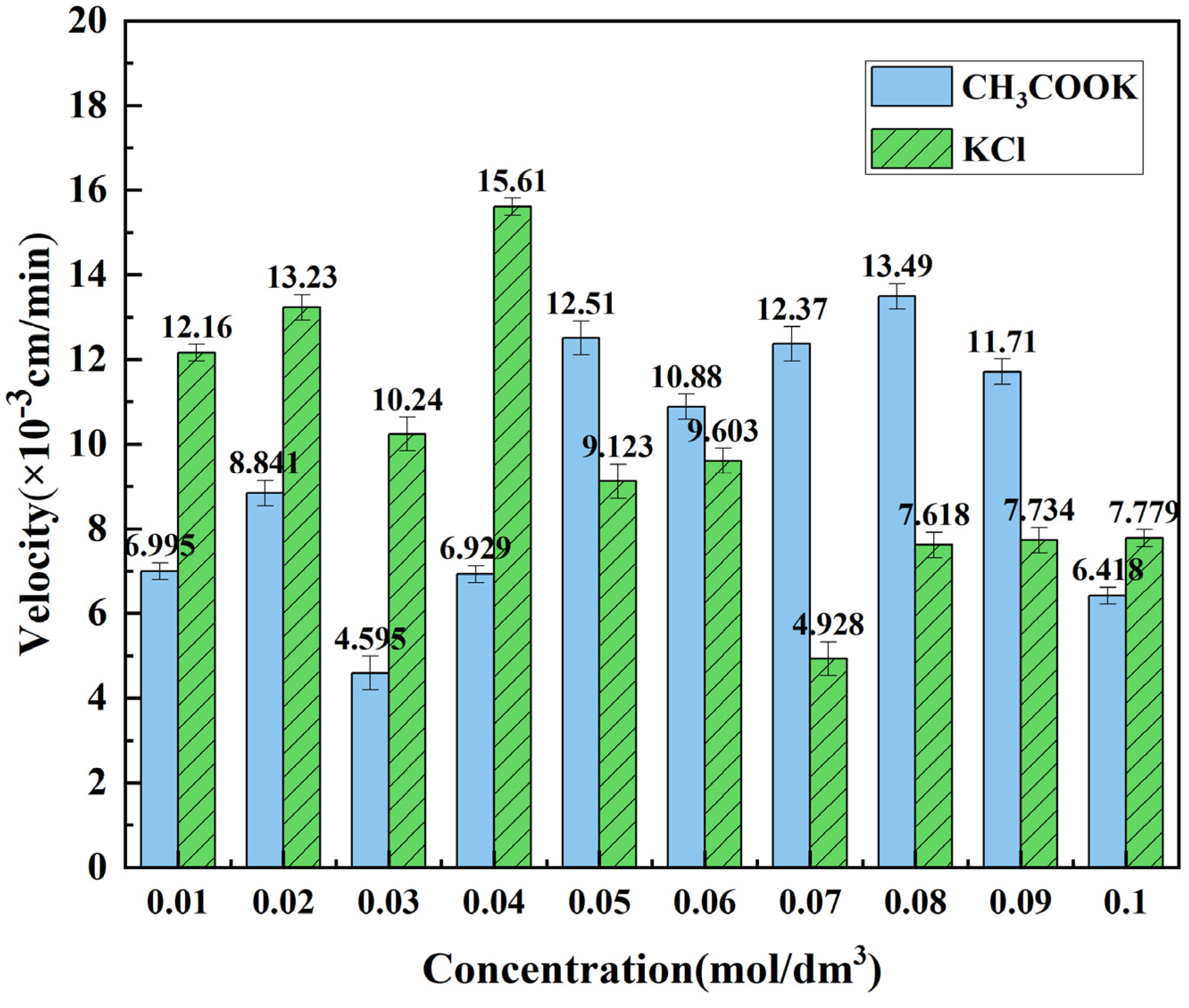
3.2. Effect of Electrolyte Solution Concentration on Stable Seepage Velocity of Halloysite Clay Mineral

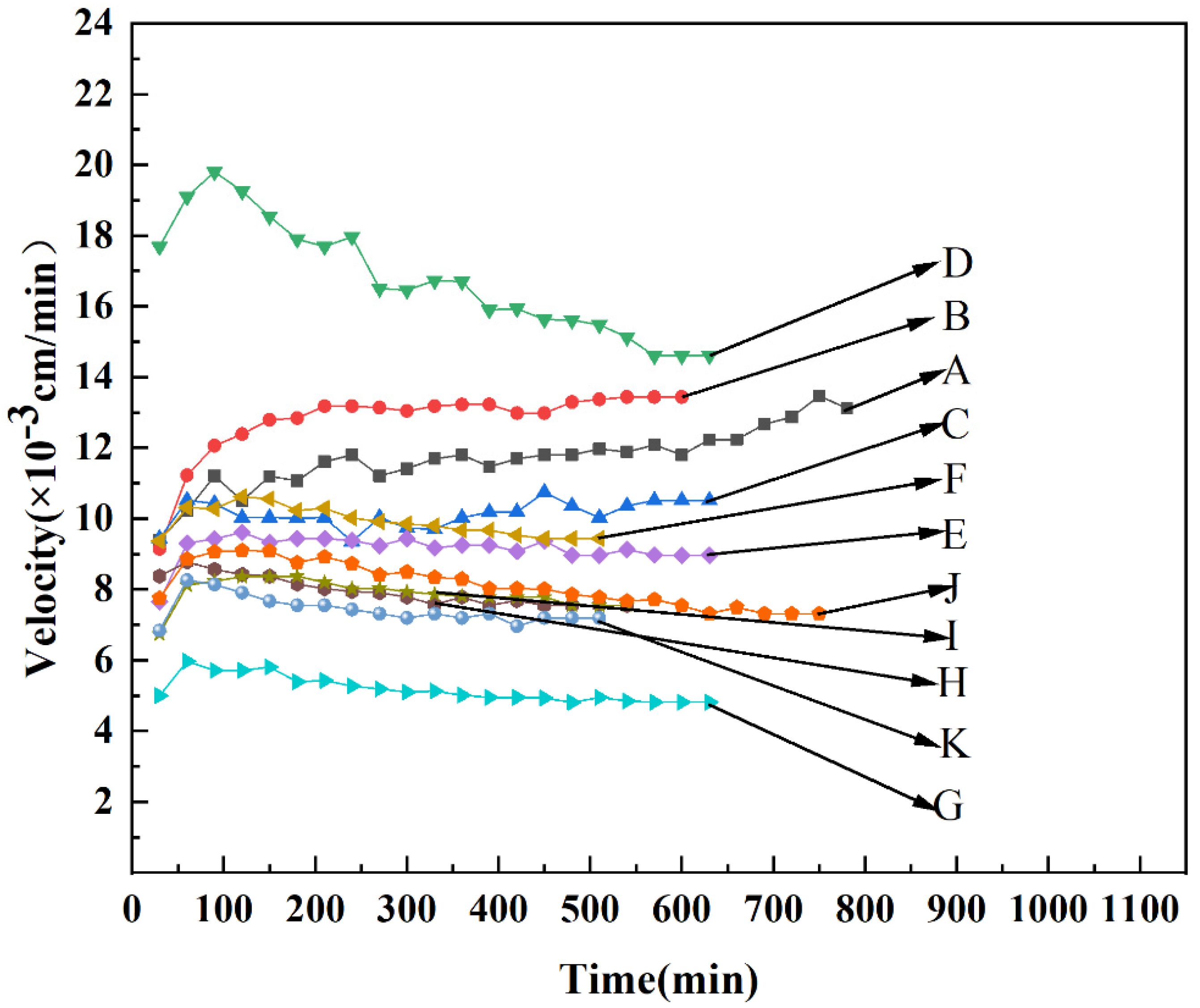
3.2.1. Effect of CH3COOK Concentration on Seepage Velocity of Halloysite Clay Mineral

To explore the different percolation velocities of the complex CH3COOK solutions in the halloysite clay mineral at different concentrations, Figure 11 and Figure 12 were plotted. From Figure 11, the equilibrium time is different at different concentrations. Under most of the concentration conditions, the velocity reaches approximate equilibrium in 100 min after the start. Figure 12 depicts the specific values for each concentration at which the osmosis rate reaches equilibrium. The concentrations with higher seepage rates are 0.05, 0.07, and 0.08 mol/dm3, with rates of 12.51 × 10⁻³ cm/min, 12.37 × 10⁻³ cm/min, 13.49 × 10⁻³ cm/min, respectively.
Based on the above experimental results for the determination of the swelling rate of halloysite clay mineral, it is desired that the selected concentration could effectively inhibit swelling while maintaining a good permeation rate. Therefore, a concentration of 0.05 mol/dm3 was chosen as the optimum concentration for the CH3COOK system. At this concentration, the equilibrium swelling rate of the halloysite clay mineral is 5.129%, and its steady seepage velocity rate is 12.51 × 10⁻³ cm/min relative to that of the single MgSO4 solution at 20.08%. Finally, 0.05 mol/dm3 was selected as the optimum concentration compared to the 0.07 mol/L concentration (with similar anti-swelling effect) because the smaller concentration could save cost and facilitate subsequent process practice.

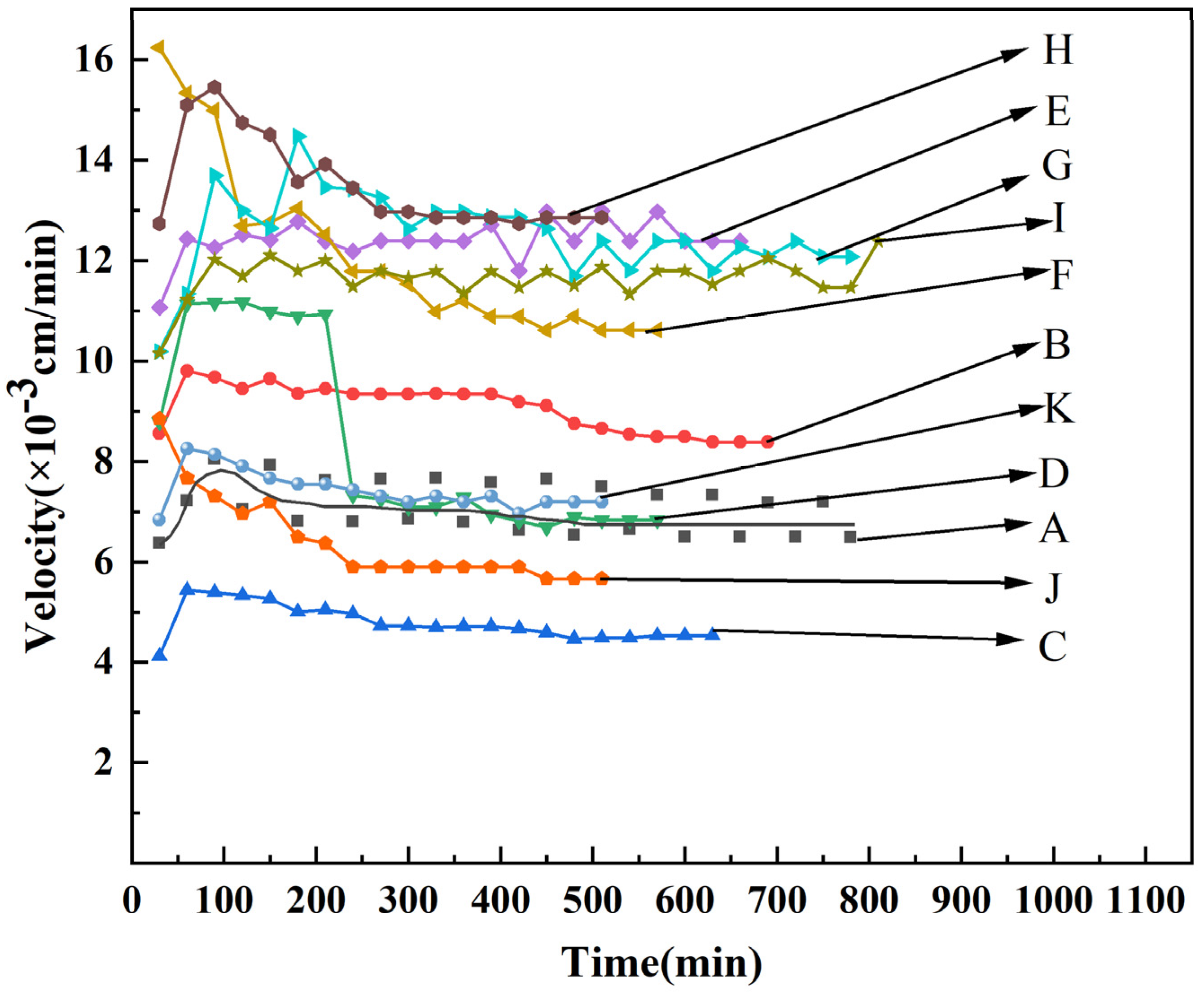
3.2.2. Effect of KCl Concentration on Seepage Velocity of Halloysite Clay Mineral

Figure 13 depicts the variation of percolation rates in the halloysite clay mineral with different concentrations of KCl complex solutions. It can be seen from the figure that the variation of the seepage velocity rate for each concentration in the KCl system is relatively stable during the experiment compared to the CH3COOK system and that the rate reaches approximate equilibrium for all concentrations at 100 min. The comparison of stable exudation rates at each concentration is shown in Figure 12. The faster exudation velocities are 12.16 × 10⁻³ cm/min, 13.23 × 10⁻³ cm/min,15.61 × 10−3 cm/min with the concentration of 0.01 mol/dm3, 0.02 mol/dm3, 0.04 mol/dm3, respectively.
In the KCl system, a concentration of 0.02 mol/dm3 is optimal when the condition needs to achieve effective swelling inhibition and does not impair the seepage velocity rate. At this concentration, the seepage velocity rate is 13.23 × 10⁻³ cm/min, while the swelling rate is 4.868%, and the relative swelling inhibition is 24.15%.

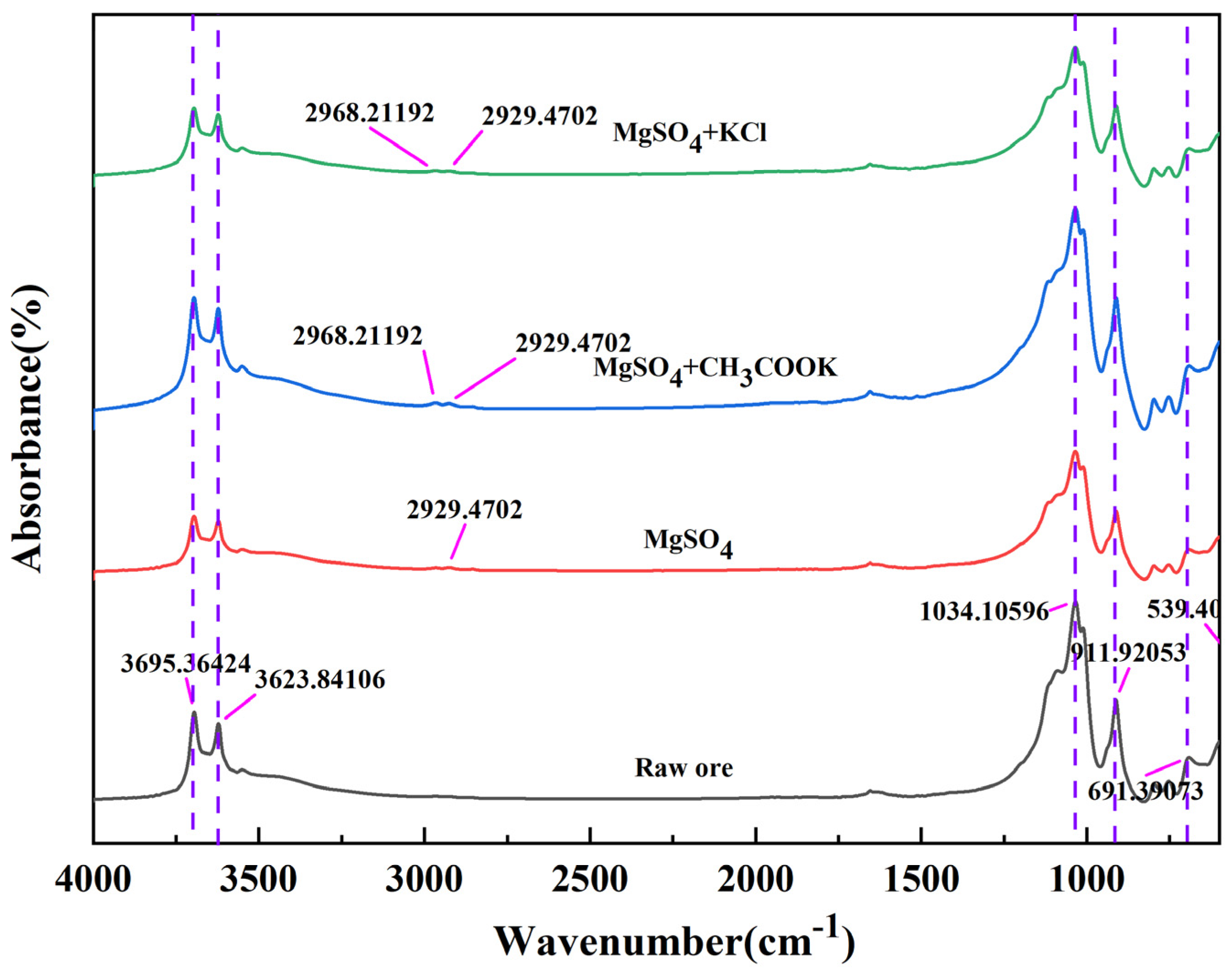
3.3. FTIR Analysis on Halloysite Clay Mineral Different Anti-Swelling Agents

To analyze the mechanism of the reduced swelling rate of halloysite clay mineral in two bulking inhibitor solutions, four types of halloysite clay minerals at the respective optimal concentrations described earlier (raw halloysite clay mineral without any chemical solution treatment, halloysite clay mineral in MgSO4 solution, halloysite clay mineral in MgSO4 and CH3COOK complex solution, and halloysite clay mineral in MgSO4 solution complexed with KCl) were characterized by FTIR spectroscopy. The raw ore in Figure 14 corresponds to the halloysite clay mineral that has not been treated with any chemical solution, and this sample is only dried for 12 h under room temperature and vacuum conditions. The other three samples were all dried and treated halloysite clay minerals, which were placed in a centrifuge tube with the corresponding solution and shaken at room temperature for 72 h. First, assemble the suction bottle and Buchner funnel. The specification of the Buchner funnel used is 150 mm. Place two layers of chronic filter paper on the Buchner funnel and wet the filter paper with distilled water to make it close to the funnel filter hole. Use a Glass rod for drainage and transfer the solid-liquid mixture after vibration to the filter paper. Connect the vacuum pump to the suction bottle through a rubber tube, open the vacuum pump, and use air pressure to filter the liquid in the solid-liquid mixture into the suction bottle, achieving solid-liquid separation. After vacuum drying for 12 h, the solid obtained through filtration was subjected to Fourier transform infrared spectroscopy analysis. An infrared spectrometer was used to analyze the ore samples before and after the experiment. The measured wave number range is 400–4000 (cm−1), and the sample is 1–2 mg. Mix with dry KBr powder at a mass ratio of 1:100. After mixing, use a tablet press to press it into thin discs. The results are shown in Figure 14.
It can be seen that there are five stretching vibrational bands on the IR curves of the original minerals near 3695, 3623, 1034, 911, and 691 cm−1, respectively. Among them, the vibrational band near 3695 cm−1 belongs to the surface hydroxyl group, while the one near 3623 cm−1 belongs to the internal hydroxyl group [28]. The absorption band at 1034 cm−1 is caused by the Si-O contraction vibration of halloysite clay mineral and other minerals, while the absorption peak near 911 cm−1 is caused by the O-H vibration. Meanwhile, Si-O-Al vibrations produce an absorption peak at 691 cm−1 [25].
The wave peaks at 691, 911, 1034, 3623, and 3695 cm−1 are weakened in the halloysite clay mineral treated with MgSO4 solution and MgSO4 + KCl solution compared to the untreated raw ore. This indicates that in both cases, new hydrogen bonds are formed between the clay mineral particles, which affects the unique wave peaks of the halloysite clay mineral itself. Meanwhile, new peaks of 2929 and 2968 cm−1 are generated in MgSO4 + CH3COOK-treated and MgSO4 + KCl-treated halloysite clay minerals. The MgSO4 + CH3COOK solution can be considered as a result of carboxyl group vibrations, indicating that halloysite clay mineral adsorbs carboxylate ions, which are attached to the hydroxyl groups on the surface of halloysite clay mineral through their carboxyl groups, avoiding the penetration of water molecules and achieving the effect of swelling inhibition [25]. Besides, the new peaks of halloysite clay mineral treated with MgSO4 + KCl might be caused by the stretching of C-H bonds, which formed new hydrogen bonds on the surface of halloysite clay mineral, thus preventing the entry of water molecules and inhibiting swelling. As aforementioned, the lower hydration energy and the appropriate ionic radius of the K+ ions allow them to preferentially enter the particle of the minerals, thus preventing the entry of water molecules and achieving the effect of inhibiting their hydration swelling. When K+ ions enter the ore, a large number of Cl ions will be free, so the H+ ions in the environment will dissociate and partly bind to Cl ions, partly inevitably in contact with the negatively charged halloysite clay mineral surface to form hydrocarbon bonds. This is the mechanism of the formation of C-H bonds.

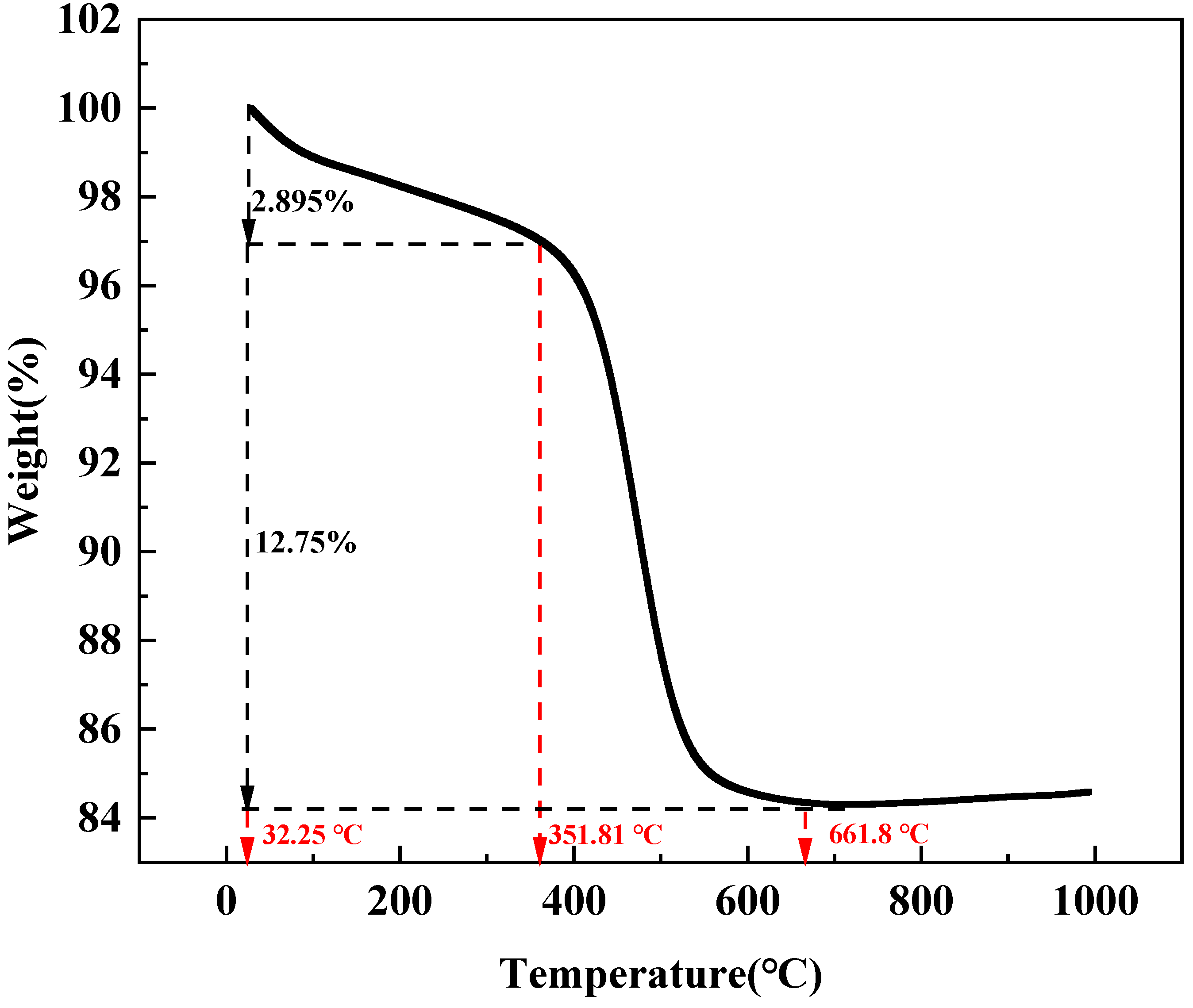
3.4. TG Analysis on Halloysite Clay Mineral

The thermogravimetric analyzer was used to detect the raw ore under the condition that the temperature range was from room temperature to 1000 °C and oxygen was used as the gas. As can be seen from Figure 15, the first weight loss of halloysite clay mineral was 2.895% when the temperature increased to 32.25–351.81 °C, and these weights belong to the category of crystalline water. Then, from 351.81 °C to 661.8 °C, the weight of halloysite clay mineral decreased by 12.75%, which belongs to the category of structural water. During the whole process, the total weight loss of halloysite clay mineral was 15.65%. This is a good indication that the water molecules enriched in the particles of halloysite clay mineral have the possibility to be replaced by some specific ions in the bulking inhibitor to achieve the purpose of bulking inhibition.

4. Conclusions

In order to effectively solve natural disasters, such as water and soil loss and landslides, this work intends to meet the requirements from the perspective of reducing the swelling rate in the hydration swelling of halloysite clay mineral. CH3COOK and KCl were combined with the conventional leaching agent MgSO4 for swelling rate measurement experiments and seepage velocity rate experiments of halloysite clay mineral, aiming to select the system that can effectively inhibit swelling as well as increase the seepage velocity rate of halloysite clay mineral.
From the experimental results in the CH3COOK combined MgSO4 solution system, the optimum concentration is 0.05 mol/dm3. At this concentration, the swelling rate of halloysite is 5.129%, the relative swelling inhibition rate is 20.08%, and the stable seepage velocity rate is 12.51 × 10⁻³ cm/min. In the KCl combined MgSO4 solution system, the concentration is 0.02 mol/dm3, and the effect of both swelling inhibition and seepage velocity aid can be achieved. At this concentration, the swelling rate of halloysite clay mineral is 4.868%, the relative swelling inhibition rate is 24.15%, and the steady seepage velocity rate is 13.23 × 10⁻³ cm/min. In addition, Fourier infrared spectroscopy detection was carried out on the halloysite clay mineral after the experiments of different composite-type swelling inhibitors. Results showed that the swelling inhibitor combined with CH3COOK solution achieved the purpose of swelling inhibition by embedding the carboxyl group into the surface particles of halloysite clay mineral, preventing the entry of water molecules. The swelling inhibitor combined with the KCl solution generated new hydrogen bonds on the surface of halloysite clay mineral, reducing the negative charge on the surface of clay particles and thus reducing their ability to attract water molecules, achieving swelling inhibition.

Author Contributions

Conceptualization, Y.X. and R.C.; methodology, Q.H.; software, Q.H.; validation, Y.X., X.D. and R.C.; formal analysis, S.H.; investigation, Q.H.; resources, J.X.; data curation, F.Z.; writing—original draft preparation, Q.H.; writing—review and editing, Y.X.; visualization, X.D.; supervision, F.Z.; project administration, R.C.; funding acquisition, Y.X. All authors have read and agreed to the published version of the manuscript.

Funding

This research was funded by the National Key Research and Development Program of China (2021YFC2902202).

Data Availability Statement

The original contributions proposed in the study are included in the article; any further inquiries can be directly contacted by the corresponding author.

Acknowledgments

Thank you to the editors and reviewers for the great effort.

Conflicts of Interest

The authors declare no conflict of interest.

References

  1. He, Z.Y.; Zhang, Z.Y.; Yu, J.X.; Chi, R. Process optimization of rare earth and aluminum leaching from weathered crust elution-deposited rare earth ore with compound ammonium salts. J. Rare Earth 2016, 34, 413–419. [Google Scholar] [CrossRef]
  2. Liu, X.; Zhou, F.; Chi, R.A.; Feng, J.; Ding, Y.; Liu, Q. Preparation of modified montmorillonite and its application to rare earth adsorption. J. Miner.-Basel 2019, 9, 747. [Google Scholar] [CrossRef] [Green Version]
  3. Sanematsu, K.; Watanabe, K. Characteristics and Genesis of Ion-Adsorption Type Rare Earth Element Deposits; Verplanck, P.L., Hitzman, M.W., Eds.; Economic Geology, Society of Economic Geologists: Littleton, CO, USA, 2016; pp. 55–79. ISBN 9781629490922. [Google Scholar]
  4. He, Z.Y.; Zhang, Z.Y.; Yu, J.X.; Zhou, F.; Xu, Y.; Xu, Z.; Chen, Z.; Chi, R. Kinetics of column leaching of rare earth and aluminum from weathered crust elution-deposited rare earth ore with ammonium salt solutions. J. Hydrometall. 2016, 163, 33–39. [Google Scholar] [CrossRef]
  5. Chi, R.A.; Tian, J. Weathered Crust Elution-Deposited Rare earth Ores; Nova Science Publishers: New York, NY, USA, 2008; pp. 142–184. ISBN 7-03-017830-0. [Google Scholar]
  6. Zhang, Z.Y.; He, Z.Y.; Zhou, F.; Zhong, C.; Sun, N.; Chi, R.A. Swelling of clay minerals in ammonium leaching of weathered crust elution-deposited rare earth ores. J. Rare Met. 2018, 37, 72–78. [Google Scholar] [CrossRef]
  7. Olphen, V.H. An introduction to clay colloid chemistry. J. Soil. Sci. 1964, 97, 290. [Google Scholar] [CrossRef]
  8. Fraldi, M.; Guarracino, F. Analytical solutions for collapse mechanisms in tunnels with arbitrary cross sections. J. International. J. Solids Struct. 2010, 47, 216–223. [Google Scholar] [CrossRef]
  9. Rahardjo, H. Application of Unsaturated Soil Mechanics in Understanding Residual Soil Behavior; 1994; pp. 45–60. [Google Scholar]
  10. Yan, S.; Liu, D.F.; Zhang, Z.Y.; Chi, R.; Xi, L. Analysis of Stability for Weathered Crust Elution-Deposited Rare Earth Ores in-situ Leaching and Selecting Leaching Agent under Non-rainfall Condition. J. Rare Earth Res. China 2021, 39, 951–961. [Google Scholar]
  11. Jin, J.; Assemi, S.; Asgar, H.; Gadikota, G.; Tran, T.; Nguyen, W.; McLennan, J.D.; Miller, J.D. Characterization of Natural Consolidated Halloysite Nanotube Structures. J. Miner. Basel 2021, 11, 1308. [Google Scholar] [CrossRef]
  12. Churchman, G.J.; Pasbakhsh, P.; Lowe, D.J.; Theng, B. Unique but diverse: Some observations on the formation, structure and morphology of halloysite. J. Clay Miner. 2016, 51, 395–416. [Google Scholar] [CrossRef]
  13. Qiu, S.; Yan, H.S.; Hong, B.G.; Long, Q.; Xiao, J.; Li, F.; Tong, L.; Zhou, X.; Qiu, T. Desorption of REEs from Halloysite and Illite: A Link to the Exploitation of Ion-Adsorption RE Ore Based on Clay Species. J. Miner.-Basel 2022, 12, 1003. [Google Scholar] [CrossRef]
  14. Zhou, J.M.; Liu, H.M.; Liu, D.; Yuan, P.; Bu, H.; Du, P.; Fan, W.; Li, M. Sorption/desorption of Eu (III) on halloysite and kaolinite. J. Appl. Clay. Sci. 2022, 216, 106356. [Google Scholar] [CrossRef]
  15. Gou, S.H.; Yin, T.X.; Qiang, G.; Qiang, X. Biodegradable polyethylene glycol-based ionic liquids for effective inhibition of shale hydration. J. Rsc. Adv. 2015, 5, 32064–32071. [Google Scholar] [CrossRef]
  16. Rosangela, D.C.; Emanuella, L.F.V.; Maurício, R.B. Design of experiments to evaluate clay swelling inhibition by different combinations of organic compounds and inorganic salts for application in water base drilling fluids. J. Appl. Clay. Sci. 2015, 105–106, 124–130. [Google Scholar] [CrossRef]
  17. Zhang, Z.Y.; Li, H.; Chi, R.A.; Long, F.; Chi, X.; Chen, W.; Chen, Z. Inhibition on the swelling of clay minerals in the leaching process of weathered crust elution-deposited rare earth ores. J. Appl. Clay. Sci. 2022, 216, 106362. [Google Scholar] [CrossRef]
  18. Kohyama, N.; Fukushima, K.; Fukami, A. Observation of the hydrated form of tubular halloysite by an electron microscope equipped with an environmental cell. J. Clay. Clay. Miner. 1978, 26, 25–40. [Google Scholar] [CrossRef]
  19. Joussein, E.; Petit, S.; Churchman, J.; Theng, B.; Righi, D.; Delvaux, B. Halloysite clay minerals-a review. Clay. Miner. 2005, 40, 382–426. [Google Scholar] [CrossRef]
  20. Diaz, M.E.; Fuentes, J.; Cerro, R.L.; Savage, M.D. Hysteresis during contact angles measurement. J. Colloid. Interf. Sci. 2010, 343, 574–583. [Google Scholar] [CrossRef]
  21. Liu, X.D.; Lu, X.C. A thermodynamic understanding of clay-swelling inhibition by potassium ions. J. Angew. Chem. 2006, 45, 6300–6303. [Google Scholar] [CrossRef]
  22. Jiang, G.; Xuan, Y.; Li, Y.; Wang, J. Inhibitive effect of potassium methylsiliconate on hydration swelling of montmorillonite. Colloid J. 2014, 76, 443–450. [Google Scholar] [CrossRef]
  23. Xuan, Y.; Jiang, G.; Li, Y.; Wang, J.; Geng, H. Inhibiting effect of dopamine adsorption and polymerization on hydrated swelling of montmorillonite. Colloids Surf. A Physicochem. Eng. Asp. 2013, 422, 50–60. [Google Scholar] [CrossRef]
  24. Svensson, P.D.; Hansen, S. Combined Salt and Temperature Impact on Montmorillonite Hydration. Clays Clay Miner. 2013, 61, 328–341. [Google Scholar] [CrossRef]
  25. Boek, E.S.; Coveney, P.V.; Skipper, N.T. Monte Carlo Molecular Modeling Studies of Hydrated Li-, Na-, and K-Smectites: Understanding the Role of Potassium as a Clay Swelling Inhibitor. J. Am. Chem. Soc. 1995, 117, 12608–12617. [Google Scholar] [CrossRef]
  26. Babadagli, T.; Al-Bemani, A.; Boukadi, F.; Al-Maamari, R. A laboratory feasibility study of dilute surfactant injection for the Yibal field, Oman. J. Pet. Sci. Eng. 2005, 48, 37–52. [Google Scholar] [CrossRef]
  27. Chen, Z.; Zhang, Z.; Liu, D.; Chi, X.; Chen, W.; Chi, R. Swelling of clay minerals during the leaching process of weathered crust elution-deposited rare earth ores by magnesium salts. Powder Technol. 2020, 367, 889–900. [Google Scholar] [CrossRef]
  28. Balan, E.; Lazzeri, M.; Saitta, A.M.; Allard, T.; Fuchs, Y.; Mauri, F. First-principles study of OH-stretching modes in kaolinite, dickite, and nacrite. Am. Miner. 2005, 90, 50–60. [Google Scholar] [CrossRef]
Figure 1. XRD patterns of experimental samples. Test target: Cu target; Scanning angle selection: 5°–90°; Scanning speed: 10°/min.
Minerals 13 00906 g001
Figure 2. Particle size composition of experimental sample. Test method: Wet method, dispersant: Distilled water, particle size testing range: 2–1000 μm.
Minerals 13 00906 g002
Figure 3. Pictures of halloysite clay mineral, (a) photo of true morphology of halloysite clay mineral, (bd) SEM of halloysite clay mineral.
Minerals 13 00906 g003
Figure 4. Schematic diagram of halloysite clay mineral swelling rate measuring device.
Minerals 13 00906 g004
Figure 5. Experimental equipment for simulated leaching.
Minerals 13 00906 g005
Figure 6. Change of swelling rate of halloysite clay mineral with time under different concentrations of MgSO4 and effect of MgSO4 concentration on equilibrium swelling rate of halloysite clay mineral. Experimental temperature: Room temperature; [MgSO4]: 0.05, 0.1, 0.15, 0.2, 0.25, 0.3 mol/dm3, distilled water. Experimental time: 100−130 h.
Minerals 13 00906 g006
Figure 7. Change of swelling rate of halloysite clay mineral with time under different concentrations of CH3COOK. Experimental temperature: Room temperature; [CH3COOK]: 0.01−0.1 mol/dm3. The A−J solution was prepared with 0.2 mol/dm3 MgSO4 solution as the solvent. [MgSO4]: 0.2 mol/dm3. Experimental time: 50−80 h.
Minerals 13 00906 g007
Figure 8. Effect of CH3COOK and KCl concentration on equilibrium swelling rate of halloysite clay mineral. Experimental temperature: Room temperature; [CH3COOK]: 0.01–0.1 mol/dm3, [KCl]: 0.01–0.1 mol/dm3. All solutions were prepared with 0.2 mol/dm3 MgSO4 solution as the solvent. Experimental time: 50–80 h.
Minerals 13 00906 g008
Figure 9. Effect of CH3COOK and KCl concentration on relative swelling inhibition of halloysite clay mineral. Experimental temperature: Room temperature; [CH3COOK]: 0.01–0.1 mol/dm3, [KCl]: 0.01–0.1 mol/dm3. All solutions were prepared with 0.2 mol/dm3 MgSO4 solution as the solvent. Experimental time: 50–80 h.
Minerals 13 00906 g009
Figure 10. Change of swelling rate of halloysite clay minerals with time under different concentrations of KCl. Experimental temperature: Room temperature; [KCl]: 0.01–0.1 mol/dm3. The A–J solution was prepared with 0.2 mol/dm3 MgSO4 solution as the solvent. [MgSO4]: 0.2 mol/dm3. Experimental time: 50–80 h.
Minerals 13 00906 g010
Figure 11. Change in seepage velocity of halloysite clay mineral with time under different concentrations of CH3COOK. Experimental temperature: Room temperature; [CH3COOK]: 0.01–0.1 mol/dm3, [A—0.01 mol/dm3 CH3COOK, B—0.02 mol/dm3 CH3COOK, C—0.03 mol/dm3 CH3COOK, D—0.04 mol/dm3 CH3COOK, E—0.05 mol/dm3 CH3COOK, F—0.06 mol/dm3 CH3COOK, G—0.07 mol/dm3 CH3COOK, H—0.08 mol/dm3 CH3COOK, I—0.09 mol/dm3 CH3COOK, J—0.1 mol/dm3 CH3COOK, K—0.2 mol/dm3 MgSO4]. The A–J solution was prepared with 0.2 mol/dm3 MgSO4 solution as the solvent. [MgSO4]: 0.2 mol/dm3. Experimental time:500–800 min.
Minerals 13 00906 g011
Figure 12. Effect of CH3COOK and KCl concentration on steady seepage velocity of halloysite clay mineral. Experimental temperature: Room temperature. [CH3COOK]: 0.01–0.1 mol/dm3, [KCl]: 0.01–0.1 mol/dm3. All solutions were prepared with 0.2 mol/dm3 MgSO4 solution as the solvent. Experimental time: 500–800 min.
Minerals 13 00906 g012
Figure 13. Change of seepage velocity of halloysite clay mineral with time under different concentrations of KCl. Experimental temperature: Room temperature; [KCl]: 0.01–0.1 mol/dm3, [A—0.01 mol/dm3 KCl, B—0.02 mol/dm3 KCl, C—0.03 mol/dm3 KCl, D—0.04 mol/dm3 KCl, E—0.05 mol/dm3 KCl, F—0.06 mol/dm3 KCl, G—0.07 mol/dm3 KCl, H—0.08 mol/dm3 KCl, I—0.09 mol/dm3 KCl, J—0.1 mol/dm3 KCl, K—0.2 mol/dm3 MgSO4]. The A–J solution was prepared with 0.2 mol/dm3 MgSO4 solution as the solvent. [MgSO4]: 0.2 mol/dm3. Experimental time: 500–800 min.
Minerals 13 00906 g013
Figure 14. FTIR spectrum of halloysite clay mineral. Sample morphology: Powder. Test mode: Powder conventional tablet pressing. Test mode: Absorption (absorbance). Wavenumber range: 400–4000.
Minerals 13 00906 g014
Figure 15. TG analysis on halloysite clay mineral. Test temperature: Room temperature or above 1000 °C. Test gas atmosphere: Oxygen. Heating rate: 10 °C/min.
Minerals 13 00906 g015
Disclaimer/Publisher’s Note: The statements, opinions and data contained in all publications are solely those of the individual author(s) and contributor(s) and not of MDPI and/or the editor(s). MDPI and/or the editor(s) disclaim responsibility for any injury to people or property resulting from any ideas, methods, instructions or products referred to in the content.

