
Analytical Approach Based on Full-Space Synergy Technology to Optimization Support Design of Deep Mining Roadway

Abstract
:1. Introduction
2. Engineering Background
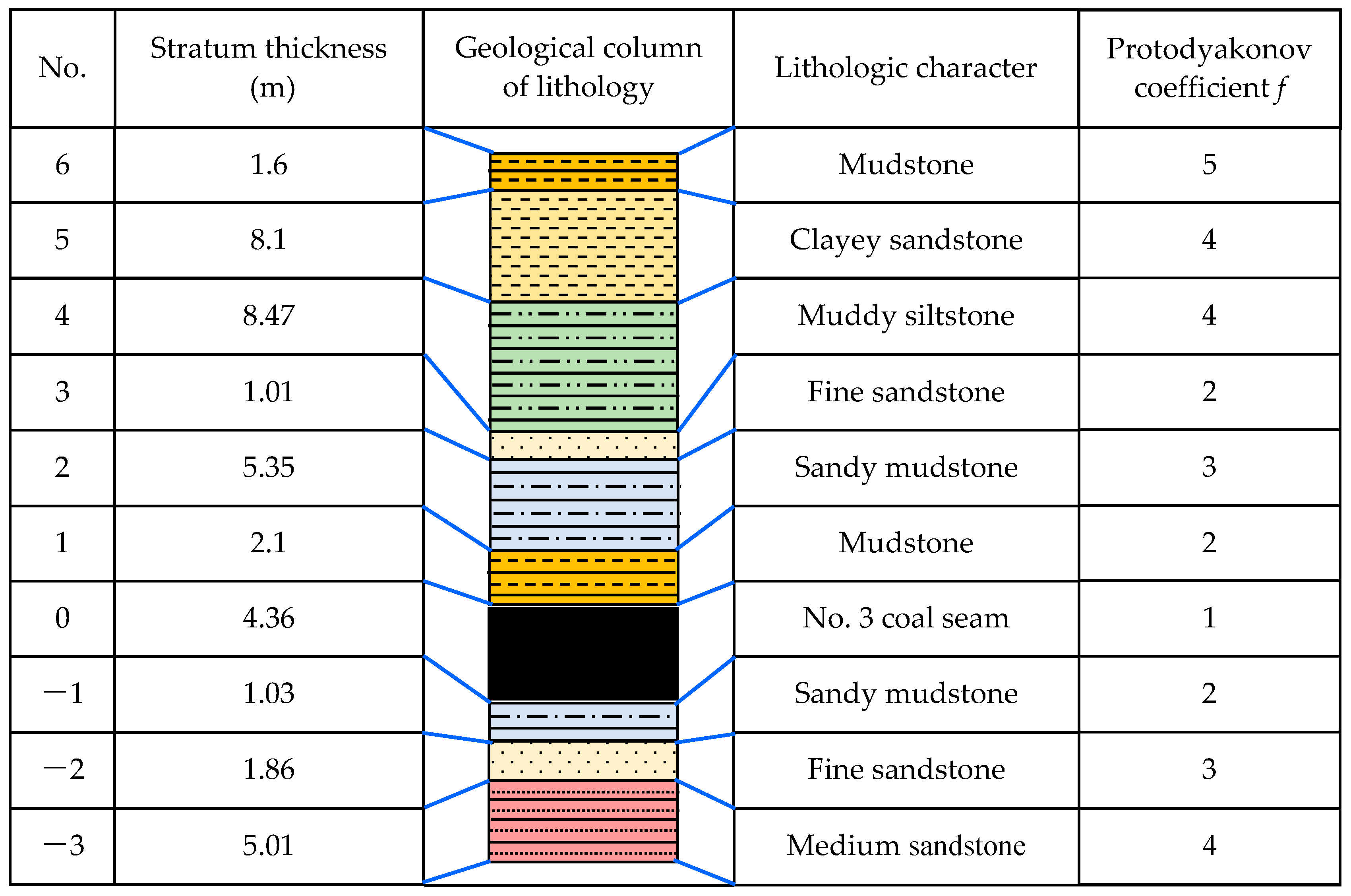
2.1. Local Geological Features
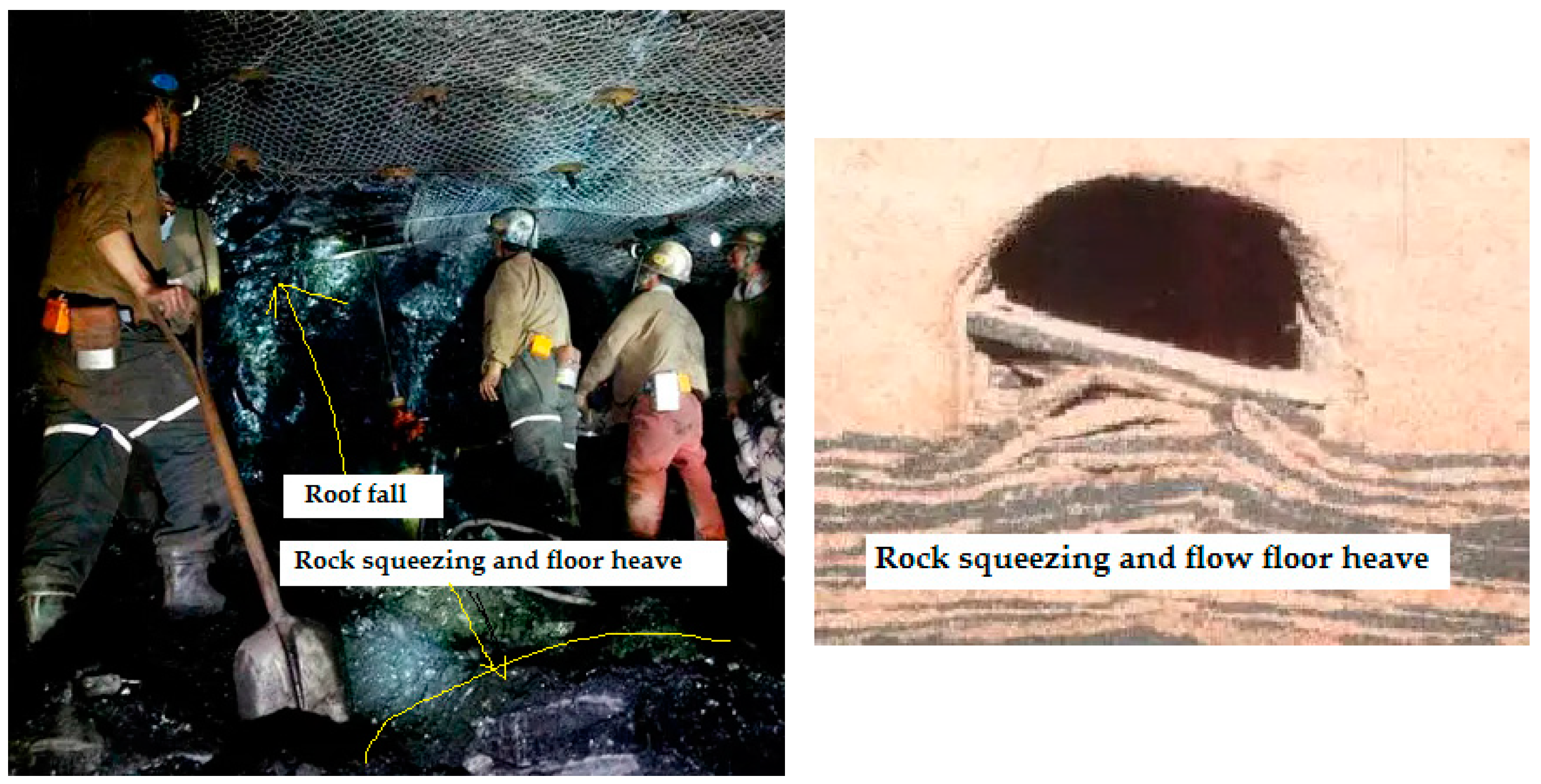
2.2. Deformation and Failure Situation Analysis of Existing Roadway
2.3. Analysis of the Large Deformation Mechanism of Roadway Surrounding Rock
- (1)
- Compared to the shallow roadway, the geological condition of the deep soft rock roadway is more complex and changeable, such as high geo-stress, developed joint fissures and unloading crack intensive belt. The geological condition difference usually brings the different technical problems of roadway support [32].
- (2)
- The direct roof is mainly mudstone or sandy mudstone, and the bedding has a certain development with abundant micro-cracks. When the roof produces a certain deflection, the rapid opening of micro-cracks leads to air entering the rock surface and makes the roof become plate0shaped, and the rock part of the mass of the roof loses its bearing capacity, further leading to the occurrence of roof failure.
- (3)
- Because there is not enough pre-tightening force on the roadway roof, the roof stress is transmitted to both sides by the roof after roadway excavation. The deformation of the roof increases the horizontal pressures on both sides of the roadway under the condition of a certain lateral pressure coefficient. In this way, the peak value of pressure reaches the roadway sides, making the side wall of the roadway produce a plastic zone, and the overall outward displacement will occur once the side wall of the roadway cannot resist the expansion pressure.
- (4)
- The support mode is not very reasonable and synergistic because this design mechanically copies the adjacent roadway support scheme of the U-shaped steel flexible support. However, in practical application, the U-shaped steel shrinkage cannot play a major role due to the deformation of the trapezoidal bracket leg. While the weathered surrounding rock is splintered under pressure, passive support alone cannot meet the requirement of surrounding rock support stability. Thus, the full-space synergy control technology should be used to improve the self-bearing capacity of the surrounding rock.
3. Method of Full-Space Synergy Control
- (1)
- The supporting strength is too high, which will not only waste support materials but also affect the excavation speed of the roadway.
- (2)
- The supporting strength is not enough, which cannot effectively control the deformation of the roadway surrounding rock and can lead to roof collapse, rib spalling, floor heave and other disasters.
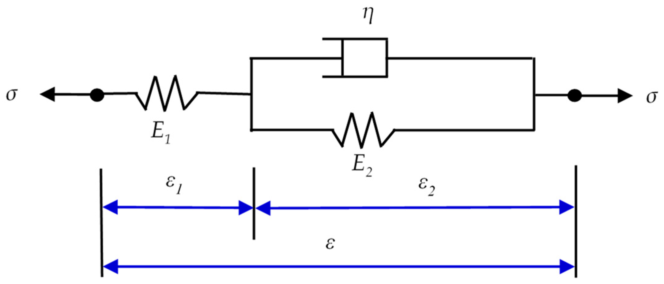
4. Basic Theoretical Model
4.1. Equation of Motion
4.2. Constitutive Equation of Rock Mass in Incremental Form
4.3. Theoretical Model of Anchored Surrounding Rock
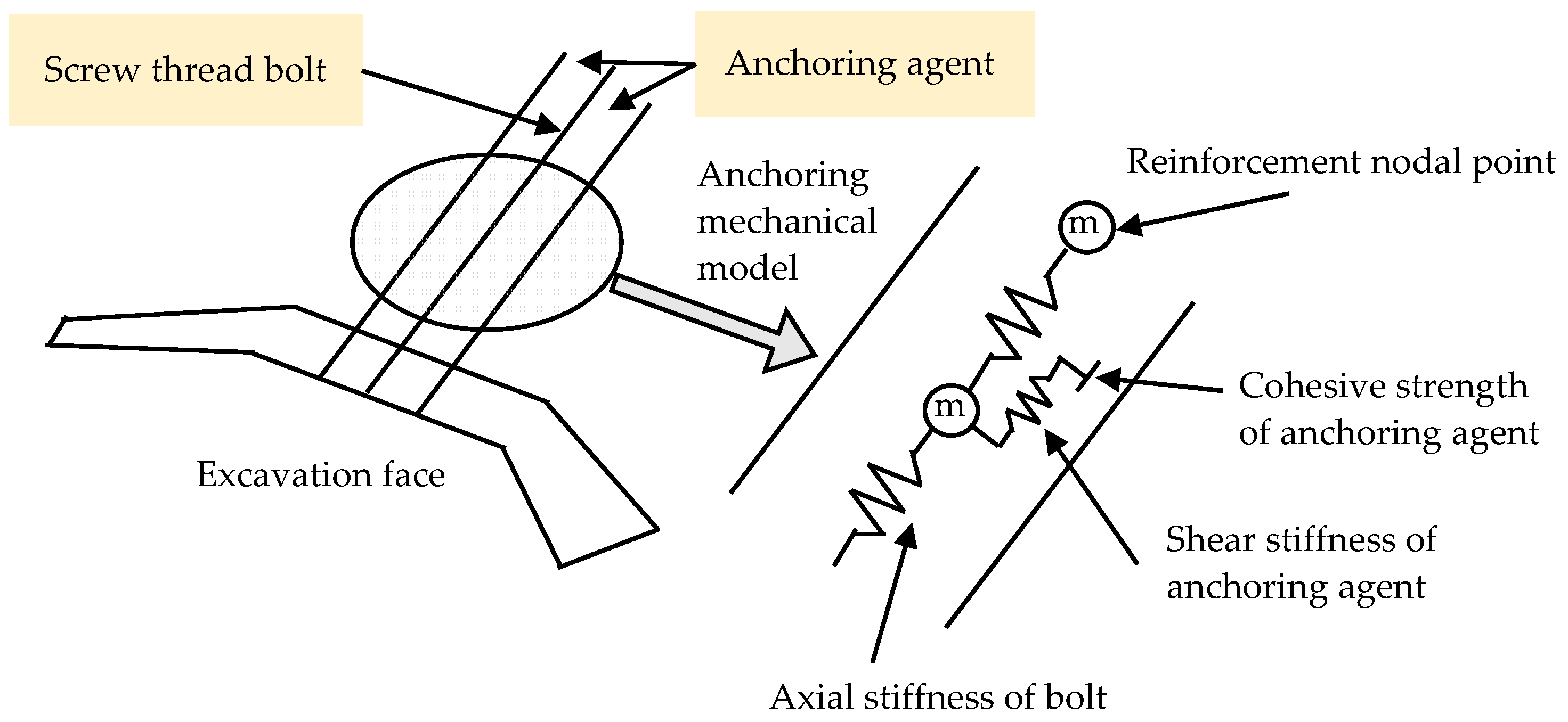
4.3.1. Anchoring Stress
4.3.2. Surrounding Rock Convergence Ratio and Bolt Parameters Design
5. Numerical Simulation Analysis of Surrounding Rock Stability
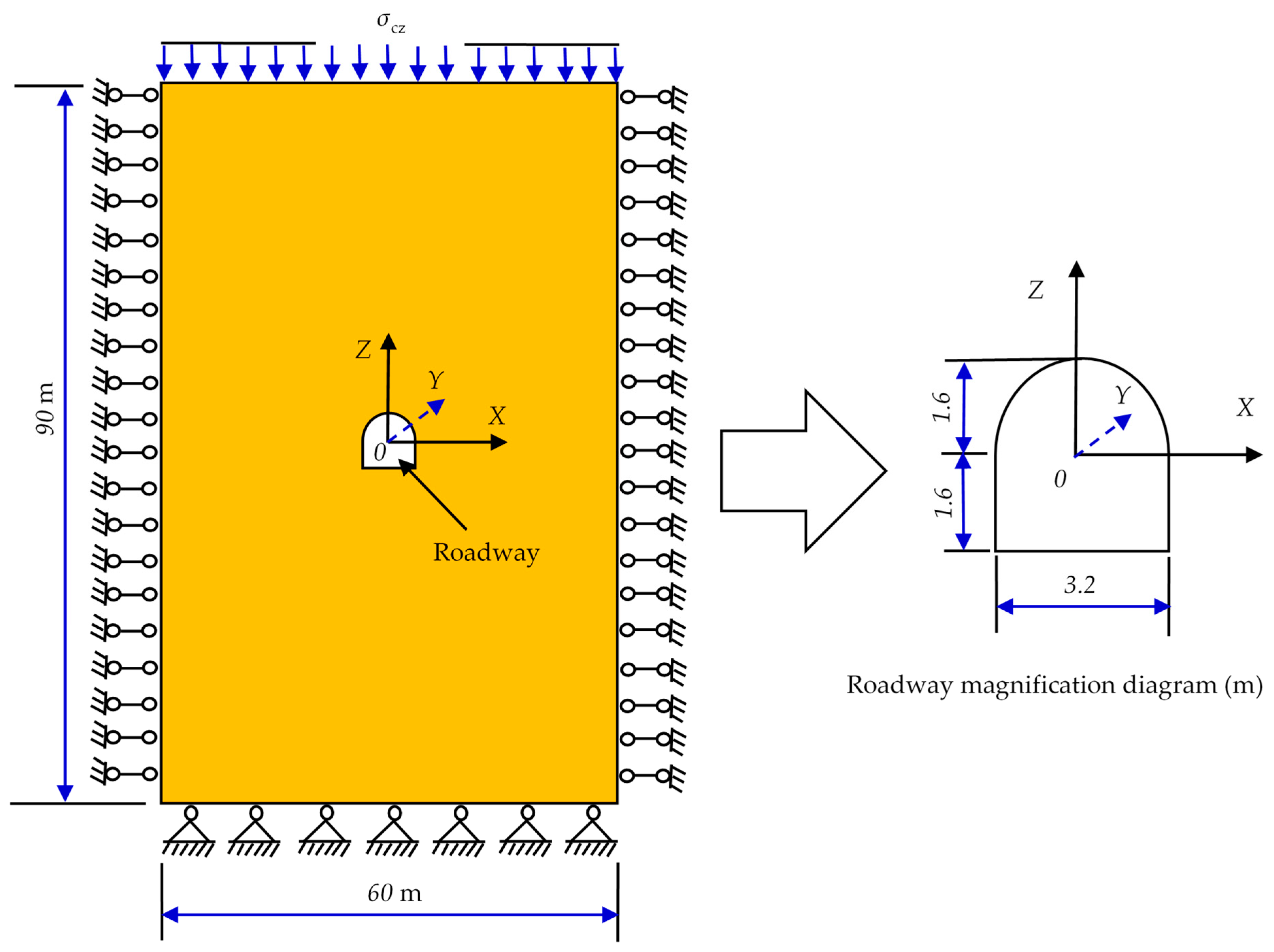
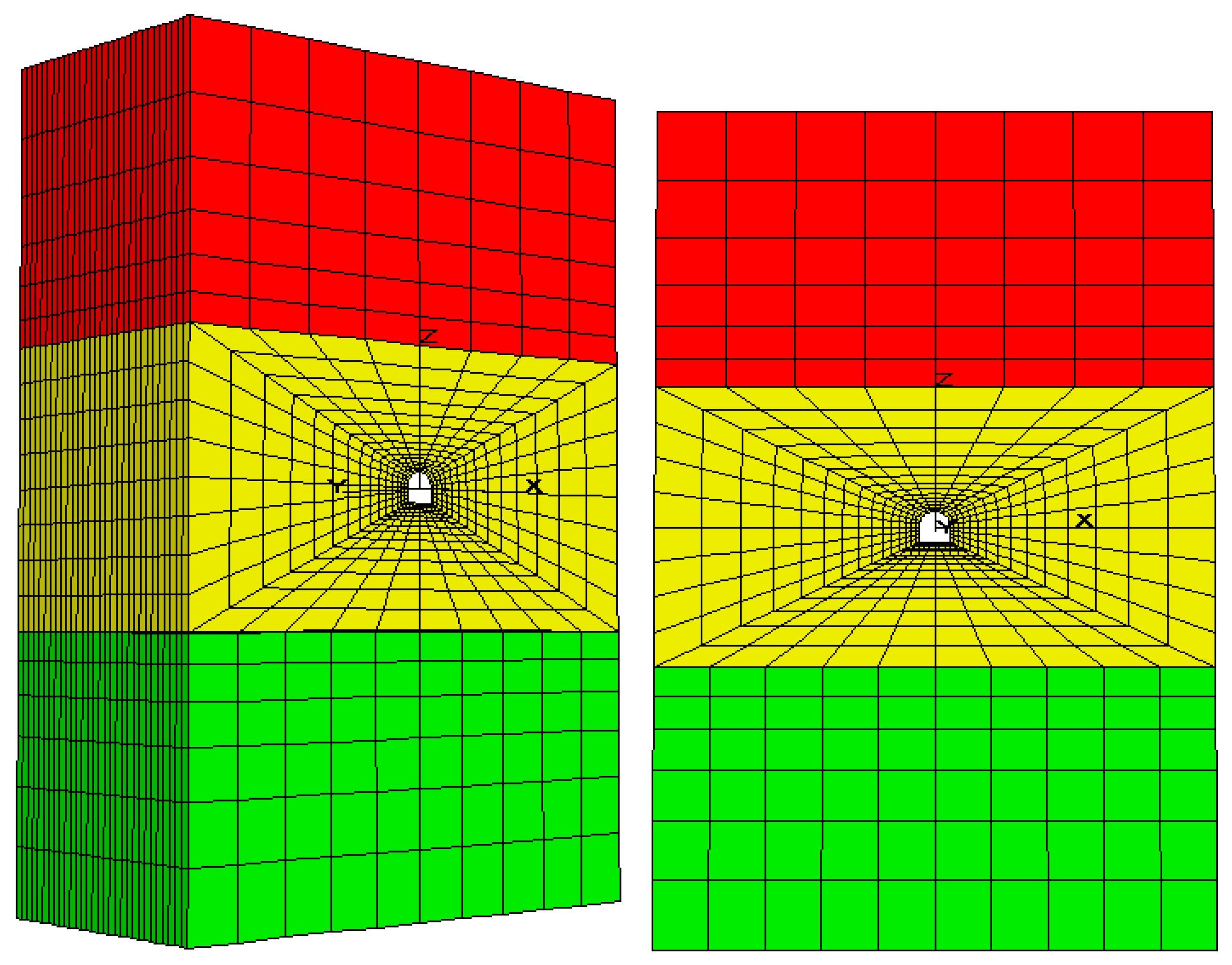
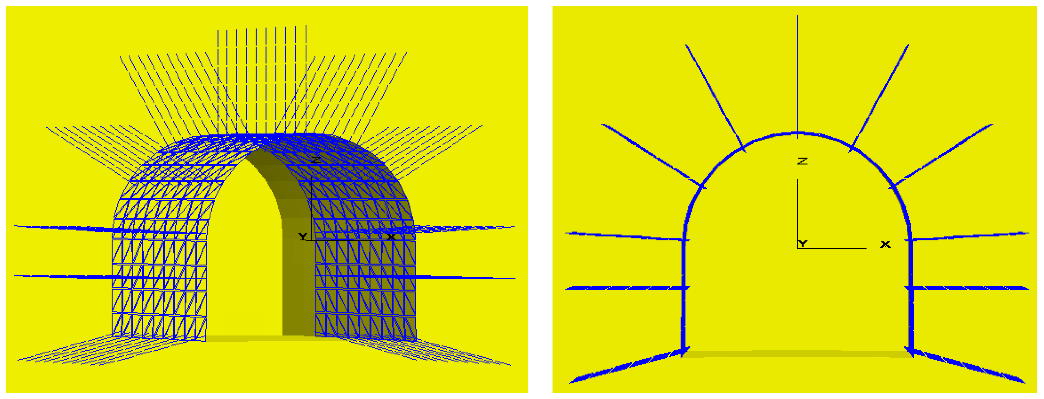
5.1. FLAC3D Numerical Computation Model
5.2. Input Parameters of Numerical Computation Model
5.3. Determinization of Modeling Scheme
5.4. Simulation Analysis of Surrounding Rock Deformation based on Orthogonal Design Method
5.4.1. Theory of Orthogonal Experimental Design
5.4.2. Orthogonal Design of Sensitivity Analysis for Bolt Parameters
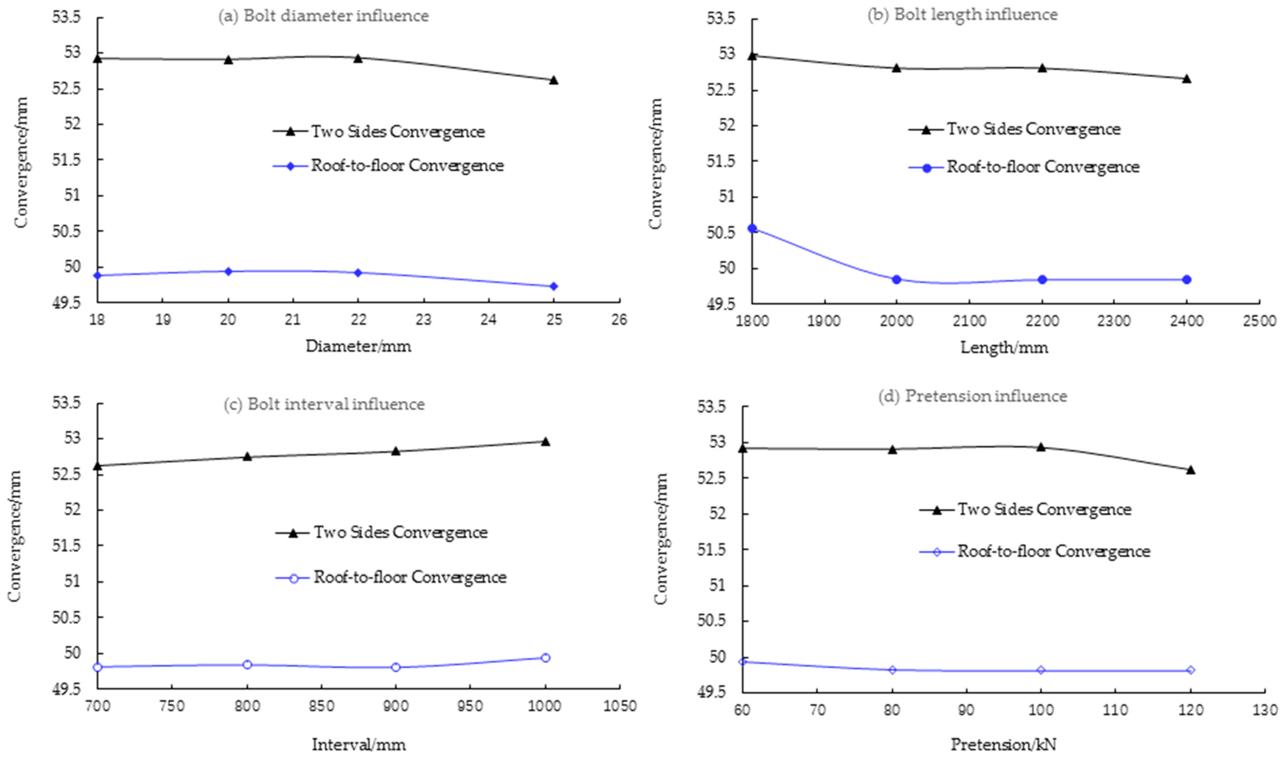
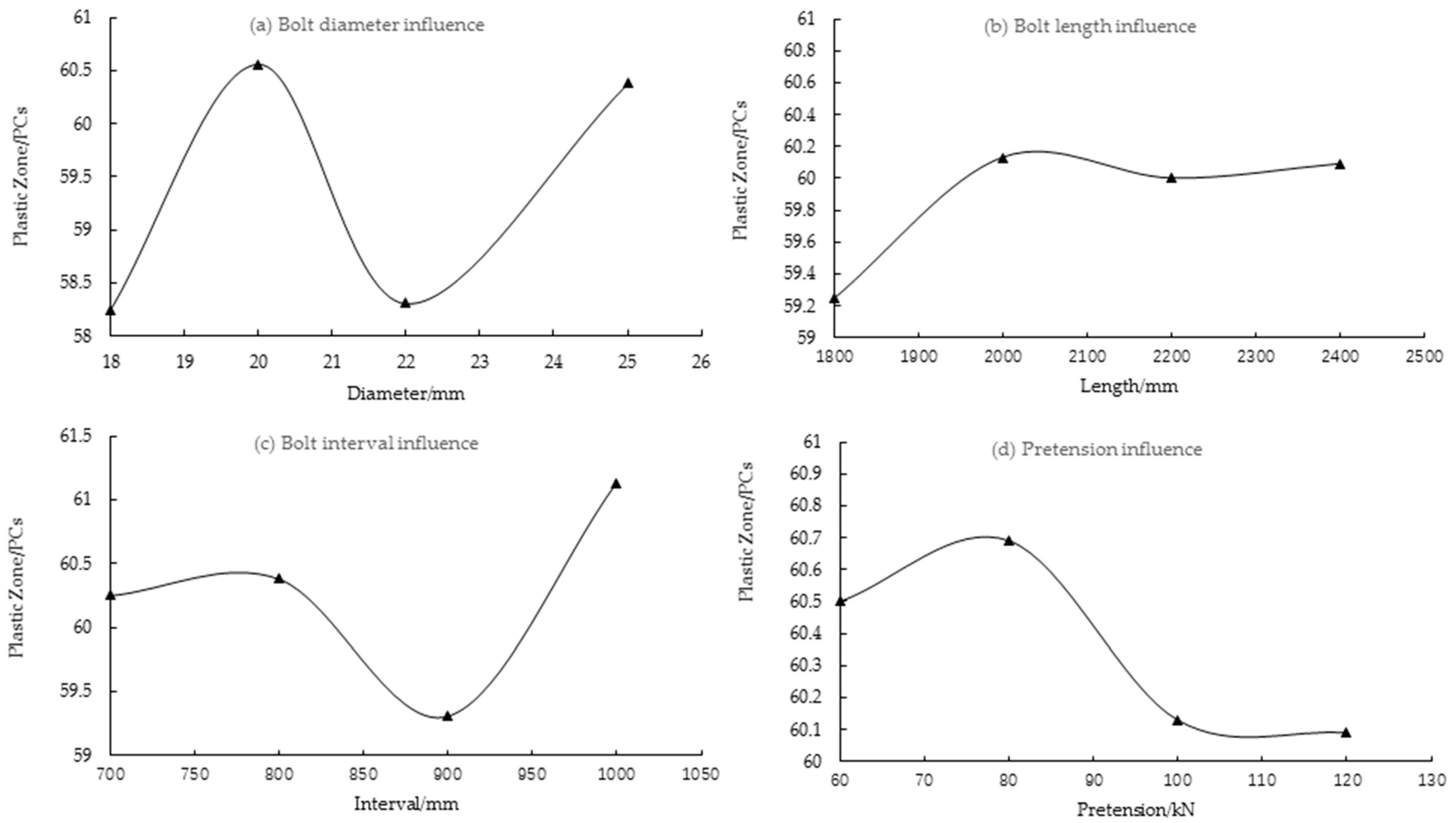
5.4.3. Orthogonal Experimental Results and Analysis
6. Discussion of Field Test and Design
6.1. Determination of Support Mode and Parameters
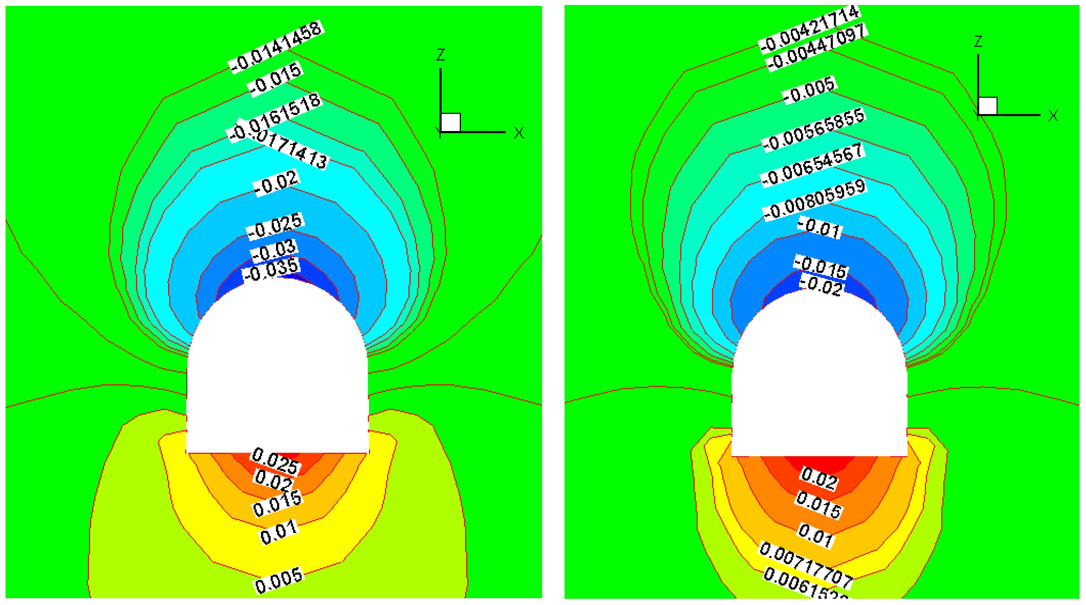
6.2. Numerical Modeling Analysis of the Roadway Surrounding Rock Deformation
6.3. Optimization Design Discussion of Support Structure
7. Conclusions
- (1)
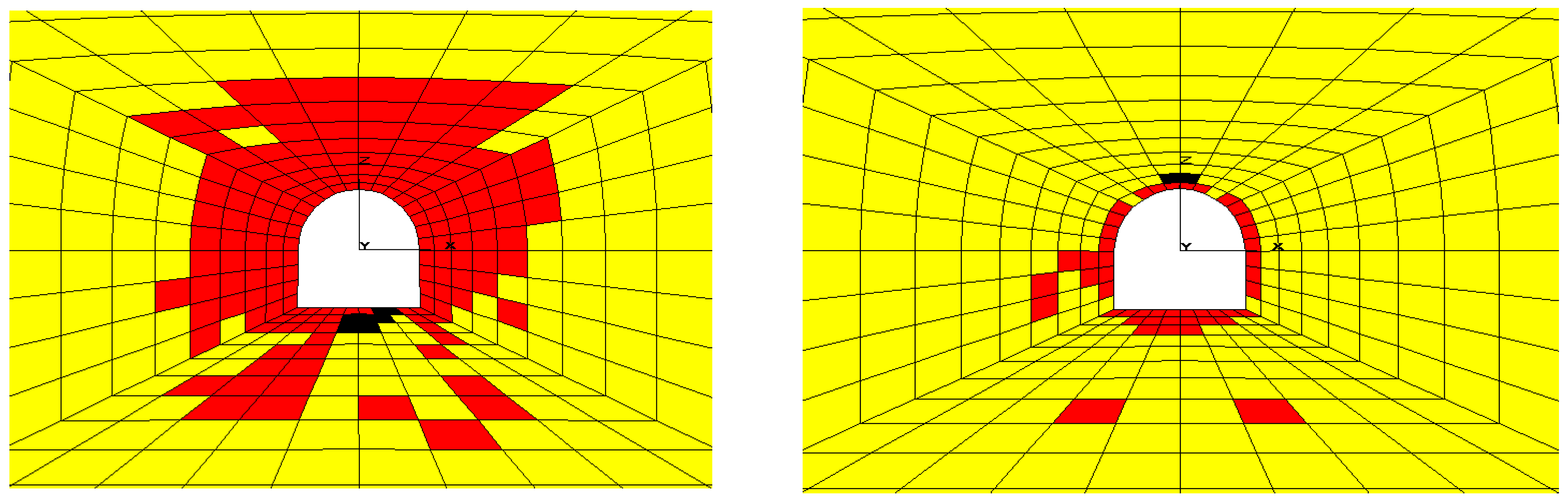
- The surrounding rock trend convergence deformation towards the interior of the roadway after roadway excavation. The convergent deformation of the surrounding rock drops sharply after conducting bolt support, which indicates that bolt support has an obvious control effect on the deformation and failure of the surrounding rock. However, the shotcrete support has a better effect on the plastic yield zone control than bolt support. Therefore, in the choice of optimization support pattern and parameters, it needs to take full advantage of different support schemes and give full play to their effectiveness to ensure the stability of the surrounding rock based on the practical engineering situation. This also can effectively ensure the stability of the roadway surrounding rock at a lower cost.
- (2)
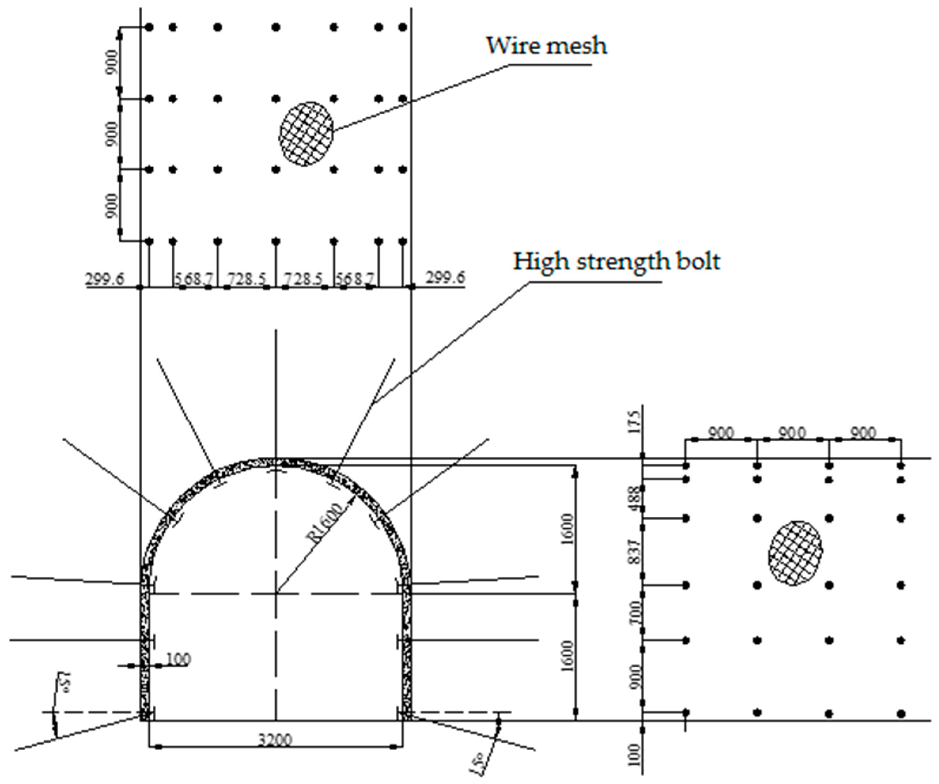
- According to the mechanical and deformation characteristics of the surrounding rock, the bearing capacity of the surrounding rock can be significantly improved after adding a shotcrete net to the bolt support, and the influence on mining was also controlled. Therefore, when the bolt-shotcrete net beam support mode is adopted, the integrity and stability of surrounding rock mass in a deep roadway can be further improved because the metal mesh can support the rubble and/or coal between the bolt and maintain the integrity of the bolt support. In addition, the roof beam can assist the inclined bolts above the two sides to connect the roof and the two sides to prevent shear yield failure; this can effectively improve the stress state of the anchoring rock formation and increase the lateral extrusion pressure to enhance the bearing capacity of the composite arch support mode.
- (3)
- According to the comparison of the deformation data of the roadway surrounding rock from references [48,49,50,51], using the proposed arch support scheme is superior to the trapezoidal or rectangular metal support. The maximum displacements of the roof, floor and two sides are below 40 mm without support and are below 22 mm after applying for the bolt-shotcrete net support. As a result, the proposed optimization support scheme and parameters with the full-space synergy control technology and bolt application have great superiorities both in economy and technology.
Author Contributions
Funding
Institutional Review Board Statement
Informed Consent Statement
Data Availability Statement
Conflicts of Interest
References
- He, M. Progress and Challenges of Soft Rock Engineering in Depth. J. China Coal Soc. 2014, 39, 1409–1417. [Google Scholar]
- Liu, F.; Cao, W.J.; Zhang, J.M.; Cao, G.G.; Guo, L.F. Current Technological Innovation and Development Direction of the 14th Five-Year Plan Period in China Coal Industry. J. China Coal Soc. 2021, 46, 1–15. [Google Scholar] [CrossRef]
- Wang, J.C.; Peng, S.S.; Li, Y. State-of-the-Art in Underground Coal Mining and Automation Technology in the United States. J. China Coal Soc. 2021, 46, 36–45. [Google Scholar] [CrossRef]
- Światek, J.; Janoszek, T.; Cichy, T.; Stoiński, K. Computational Fluid Dynamics Simulations for Investigation of the Damage Causes in Safety Elements of Powered Roof Supports—A Case Study. Energies 2021, 14, 1027. [Google Scholar] [CrossRef]
- Wojtecki, Ł.; Iwaszenko, S.; Apel, D.B.; Cichy, T. An Attempt to Use Machine Learning Algorithms to Estimate the Rockburst Hazard in Underground Excavations of Hard Coal Mine. Energies 2021, 14, 6928. [Google Scholar] [CrossRef]
- Huang, X.; Liu, Q.S.; Qiao, Z. Research on Large Deformation Mechanism and Control Method of Deep Soft Roadway in Zhuji Coal Mine. Rock Soil Mech. 2012, 33, 827–834. [Google Scholar] [CrossRef]
- Yu, Y.; Wang, X.Y.; Bai, J.B.; Zhang, L.Y.; Xia, H.C. Deformation Mechanism and Stability Control of Roadway Surrounding Rock with Compound Roof: Research and Applications. Energies 2020, 13, 1350. [Google Scholar] [CrossRef]
- Wang, W.M.; Gao, X.; Jing, J.D.; Liu, C.L.; Zhou, J.H. Study on Roof Bolting with Anchor and Wire Mesh Coupling Support Technology in Weakly Consolidated Soft Rock Roadway. Coal Sci. Technol. 2014, 42, 23–26. [Google Scholar]
- Hou, C.J.; Wang, X.Y.; Bai, J.B.; Meng, N.K.; Wu, W.D. Basic Theory and Technology Study of Stability Control for Surrounding Rock in Deep Roadway. J. China Univ. Min. Technol. 2021, 50, 1–12. [Google Scholar]
- Stankus, J.C.; Peng, S.S. Floor Bolting for Control of Mine Floor Heave. Int. J. Rock Mech. Min. Sci. Geomech. Abstr. 1994, 46, 1099–1102. [Google Scholar]
- Du, X.J.; Su, X.G.; Yuan, H.H.; Li, B.K.; Zhang, S.; Yang, Z.Y. Control of Surrounding Rock Stability Based on Failure Characteristics Analysis of Roadway Shoulders. Saf. Coal Min. 2015, 46, 62–65. [Google Scholar] [CrossRef]
- Jiang, L.S.; Zhang, P.P.; Kong, P.; Jia, J.F.; Ma, N.; Shu, J.M.; Zhang, C. Rib-Control Support Principle Based on the Foundation Rigidity of Coal Mine Roadways. J. China Coal Soc. 2019, 44, 1020–1029. [Google Scholar] [CrossRef]
- Yu, Y.; Lu, J.F.; Chen, D.C.; Pan, Y.X.; Zhao, X.Q.; Zhang, L.Y. Study on the Stability Principle of Mechanical Structure of Roadway with Composite Roof. Minerals 2021, 11, 1003. [Google Scholar] [CrossRef]
- Wu, P.; Chen, L.; Li, M.; Wang, L.; Wang, X.F.; Zhang, W. Surrounding Rock Stability Control Technology of Roadway in Large Inclination Seam with Weak Structural Plane in Roof. Minerals 2021, 11, 881. [Google Scholar] [CrossRef]
- Yang, R.S.; Li, Y.L.; Guo, D.M. Deformation and Failure Causes and Support Technology of Deep High Stress Soft Rock Roadway. J. Min. Saf. Eng. 2017, 34, 1035–1041. [Google Scholar]
- Liu, Q.S.; Liu, X.W.; Huang, X.; Liu, B. Research on the Floor Heave Reasons and Supporting Measures of Deep Soft-Fractured Rock Roadway. J. China Coal Soc. 2013, 38, 566–572. [Google Scholar]
- Ma, N.J.; Zhao, X.D.; Zhao, Z.Q.; Li, J.; Guo, X.F. Stability Analysis and Control of Roof in Deep Mining Roadway. J. China Coal Soc. 2015, 40, 2287–2295. [Google Scholar] [CrossRef]
- Li, G.; Ma, F.; Guo, J.; Zhao, H.; Liu, G. Study on Deformation Failure Mechanism and Support Technology of Deep Soft Rock Roadway. Eng. Geol. 2019, 264, 105262. [Google Scholar] [CrossRef]
- He, M.C.; Xie, H.P.; Peng, S.P.; Jiang, Y.D. Research on Mechanics of Rock Mass in Deep Mining. Chin. J. Rock Mech Eng. 2005, 16, 2803–2813. [Google Scholar]
- Wang, R.C.; Tan, Y.L. Experimental study on failure mechanism of soft rock roadway in Yangcheng coal. Appl. Mech. Mater. 2014, 675–677, 1381–1384. [Google Scholar] [CrossRef]
- Cheon, D.S.; Jeon, S.; Park, C.; Song, W.K.; Park, E.S. Characterization of Brittle Failure Using Physical Model Experiments under Polyaxial Stress Conditions. Int. J. Rock Mech. Min. Sci. 2011, 48, 152–160. [Google Scholar] [CrossRef]
- Sun, L.H.; Yang, B.S.; Sun, C.D.; Li, X.; Wang, Z.W. Experimental Research on Mechanism and Controlling of Floor Heave in Deep Soft Rock Roadway. J. Min. Saf. Eng. 2017, 34, 236–242. [Google Scholar] [CrossRef]
- Si, X.F.; Huang, L.Q.; Gong, F.Q.; Liu, X.L.; Li, X.B. Experimental Investigation on Influence of Loading Rate on Rockburst in Deep Circular Tunnel under True-Triaxial Stress Condition. J. Cent. South Univ. 2020, 27, 2914–2929. [Google Scholar] [CrossRef]
- Zhao, X.Z.; Zhang, H.W.; Cao, C.; Zhang, M.; Zhang, H.D.; Han, J. Optimization of Bolt Rib Spacing and Anchoring Force under Different Conditions of Surrounding Rock. Rock Soil Mech. 2018, 39, 1263–1270, 1280. [Google Scholar] [CrossRef]
- Yu, W.J.; Wu, G.S.; Liu, Z.; Huang, Z.; Liu, F.F.; Ren, H. Uniaxial Compression Test of Coal-Rock-Bolt Anchorage Body and Mechanical Mechanisms of Bolts. Chin. J. Rock Mech. Eng. 2020, 39, 57–68. [Google Scholar] [CrossRef]
- Jing, H.W.; Yin, Q.; Zhu, D.; Sun, Y.J.; Wang, B. Experimental Study on the Whole Process of Instability and Failure of Anchorage Structure in Surrounding Rock of Deep-Buried Roadway. J. China Coal Soc. 2020, 45, 889–901. [Google Scholar] [CrossRef]
- Li, B.; Gao, P.; Cao, Y.; Gong, W.; Zhang, S.; Zhang, J. Damage and Failure Characteristics of Surrounding Rock in Deep Circular Cavern under Cyclic Dynamic Load: A True Triaxial Experiment Investigation. Minerals 2022, 12, 134. [Google Scholar] [CrossRef]
- Wu, G.H.; Yu, W.J.; Liu, Z.; Liu, F.F.; Huang, Z. Inversion Method of Mechanical Parameters of Rock Mass in Soft Rock Roadway and Its Engineering Application. Ind. Min. Auto. 2018, 44, 41–48. [Google Scholar] [CrossRef]
- Wang, D.; Jiang, Y.J.; Sun, X.M.; Luan, H.J.; Zhang, H. Nonlinear Large Deformation Mechanism and Stability Control of Deep Soft Rock Roadway: A Case Study in China. Sustainability 2019, 11, 6243. [Google Scholar] [CrossRef]
- Lecomte, A.; Salmon, R.; Yang, W.; Marshall, A.; Purvis, M.; Prusek, S.; Bock, S.; Gajda, L.; Dziura, J.; Niharra, A.M. Case Studies and Analysis of Mine Shafts Incidents in Europe. In Proceedings of the International Conference on Shaft Design and Construction, London, UK, 24–26 April 2012; Available online: https://hal-ineris.archives-ouvertes.fr/ineris-00973661 (accessed on 1 April 2012).
- Song, G.; Stankus, J.C. Control Mechanism of a Tensioned Bolt System in the Laminated Roof with a Large Horizontal Stress. In Proceedings of the 16th International Conference on Ground Control in Mining, Morgantown, WV, USA, 1 December 1996; pp. 167–172. [Google Scholar]
- Kang, H. Support Technologies for Deep and Complex Roadways in Underground Coal Mines: A Review. Int. J. Coal Sci. Technol. 2014, 1, 261–277. [Google Scholar] [CrossRef]
- Kwasniewski, J.; Dominik, I.; Lalik, K.; Sakeb, A.A. Analysis of Dependence between Stress Change and Resonance Frequency for Self-Excited Acoustical System. Sol. State Pheno. 2014, 208, 194–199. [Google Scholar] [CrossRef]
- Skrzypkowski, K.; Korzeniowski, W.; Zagórska, A. Modified Rock Bolt Support for Mining Method with Controlled Roof Bending. Energies 2020, 13, 1868. [Google Scholar] [CrossRef]
- Zhao, C.X.; Li, Y.M.; Liu, G.; Meng, X.R. Mechanism Analysis and Control Technology of Surrounding Rock Failure in Deep Soft Rock Roadway. Eng. Fail. Ana. 2020, 115, 104611. [Google Scholar] [CrossRef]
- Malkowski, P. The Impact of the Physical Model Selection and Rock Mass Stratification on the Results of Numerical Calculations of the State of Rock Mass Deformation around the Roadways. Tunn. Undergr. Space Technol. 2015, 50, 365–375. [Google Scholar] [CrossRef]
- Zhu, W.X.; Jing, H.W.; Yang, L.J.; Pan, B.; Su, H.J. Strength and Deformation Behaviors of Bedded Rock Mass under Bolt Reinforcement. Int. J. Min. Sci. Technol. 2018, 28, 593–599. [Google Scholar] [CrossRef]
- Guo, X.; Zheng, X.; Li, P.; Lian, R.; Liu, C.; Shahani, N.M.; Wang, C.; Li, B.; Xu, W.; Lai, G. Full-Stress Anchoring Technology and Application of Bolts in the Coal Roadway. Energies 2021, 14, 7475. [Google Scholar] [CrossRef]
- Tang, B.; Yeboah, M.; Cheng, H.; Tang, Y.Z.; Yao, Z.S.; Wang, C.B.; Rong, C.X.; Wang, Z.H.; Liu, Q.S. Numerical Study and Field Performance of Rockbolt Support Schemes in TBM-Excavated Coal Mine Roadways: A Case Study. Tunn. Undergr. Space Technol. 2021, 115, 104053. [Google Scholar] [CrossRef]
- Zuo, J.P.; Sun, Y.J.; Wen, J.H.; Wu, G.S.; Yu, M.L. Full-Space Collaborative Control Technology and Its Application for Deeply Buried Roadways. J. Tsinghua Univ. 2021, 25, 853–862. [Google Scholar] [CrossRef]
- Itasca Consulting Group Inc. Fast Lagrangian Analysis of Continua (FLAC). Available online: https://www.itascacg.com/software/FLAC3D (accessed on 10 December 2021).
- Jiang, P.; Kang, H.; Wang, Z.; Liu, Q.; Yang, J.; Gao, F.; Wang, X.; Zhang, Q.; Zheng, Y.; Wang, H. Principle, Technology and Application of Soft Rock Roadway Strata Control by Means of “Rock Bolting, U-Shaped Yielding Steel Arches and Back Filling” in Synergy in 1000 M Deep Coal Mines. J. China Coal Soc. 2020, 45, 1020–1035. [Google Scholar] [CrossRef]
- Fan, L.; Wang, W.; Yuan, C.; Peng, W. Research on Large Deformation Mechanism of Deep Roadway with Dynamic Pressure. Energy Sci. Eng. 2020, 8, 3348–3364. [Google Scholar] [CrossRef]
- Kang, H. Sixty Years Development and Prospects of Rock Bolting Technology for Underground Coal Mine Roadways in China. J. China Univ. Mining Technol. 2016, 45, 1071–1081. [Google Scholar]
- Wang, W.C.; Wang, Z.; Feng, Z.B.; Xu, Y.J. Research on Bolt-Mesh-Anchor Coupling Support Technology of Gateway with Deep Soft Rock Roadway. Coal Technol. 2019, 38, 8–11. [Google Scholar] [CrossRef]
- Benmokrane, B.; Chennouf, A.; Mitri, H.S. Laboratory Evaluation of Cement-Based Grouts and Grouted Rock Anchors. Int. J. Rock Mech. Min. Sci. 1995, 32, 633–642. [Google Scholar] [CrossRef]
- Zhou, W. Advanced Rock Mechanics; China Water and Power Press: Beijing, China, 1990. [Google Scholar]
- Lu, Y.; Wang, L.; Zhang, B. An Experimental Study of a Yielding Support for Roadways Constructed in Deep Broken Soft Rock under High Stress. Min. Sci. Technol. 2011, 21, 839–844. [Google Scholar] [CrossRef]
- Xie, Z.Z.; Zhang, N.; Han, C.L.; An, Y.P. Research on Principle and Application of Roof Thick Layer Cross-Boundary Anchorage in Coal Roadways. Chin. J. Rock Mech. Eng. 2021, 40, 1195–1208. [Google Scholar]
- Zhang, K.; Zhang, G.; Hou, R. Stress Evolution in Roadway Rock Bolts during Mining in a Fully Mechanized Longwall Face, and an Evaluation of Rock Bolt Support Design. Rock Mech. Rock Eng. 2015, 48, 333–344. [Google Scholar] [CrossRef]
- Gao, F.; Wang, X. Analyis on Sensitive Normal Test of Bolt Support Parameters for Mining Gateway. Coal Sci. Technol. 2007, 11, 68–72. [Google Scholar] [CrossRef]


| Location | Density | Shear Modulus | Bulk Modulus | Strength of Extension | Cohesion | Internal Friction Angle | Dilation Angle |
|---|---|---|---|---|---|---|---|
| ρ/kg·m−3 | G/MPa | K/Mpa | σt/Mpa | C/Mpa | φ/° | ψ/° | |
| Roof layer | 2400 | 3836 | 4363 | 0.70 | 1.30 | 28 | 0 |
| Coal seam | 1400 | 1600 | 3467 | 0.20 | 0.60 | 28 | 0 |
| Floor layer | 2510 | 1670 | 2227 | 0.40 | 1.50 | 30 | 5 |
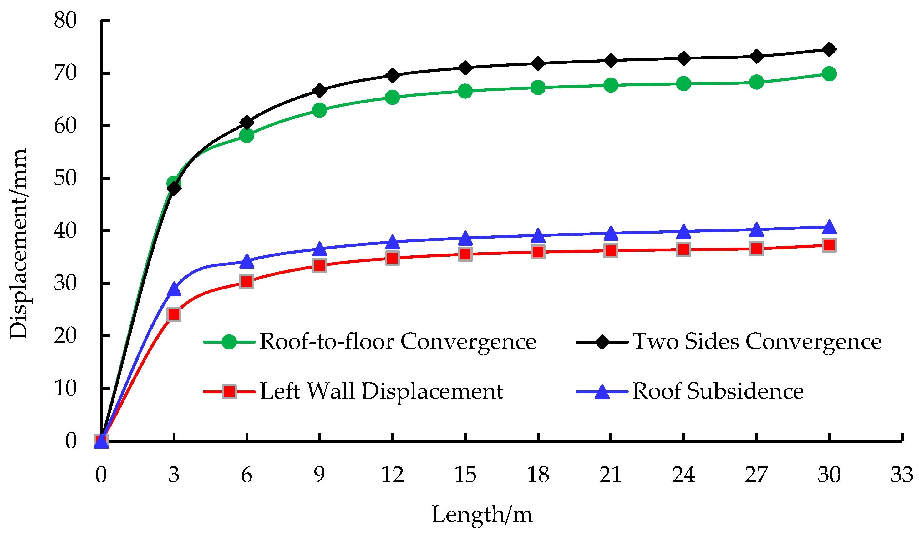
| Excavation Length | Roof Subsidence | Floor Heave | Roof-to-Floor Convergence | Left Displacement | Right Displacement | Left-to-Right Convergence |
|---|---|---|---|---|---|---|
| (m) | (mm) | (mm) | (mm) | (mm) | (mm) | (mm) |
| 3 | −28.943 | 20.098 | 49.041 | 24.068 | −24.027 | 48.095 |
| 6 | −34.29 | 23.839 | 58.129 | 30.329 | −30.308 | 60.637 |
| 9 | −36.579 | 26.346 | 62.925 | 33.357 | −33.332 | 66.689 |
| 12 | −37.877 | 27.485 | 65.362 | 34.795 | −34.772 | 69.567 |
| 15 | −38.618 | 27.947 | 66.565 | 35.517 | −35.495 | 71.012 |
| 18 | −39.125 | 28.108 | 67.233 | 35.934 | −35.912 | 71.846 |
| 21 | −39.534 | 28.135 | 67.669 | 36.215 | −36.193 | 72.408 |
| 24 | −39.896 | 28.09 | 67.986 | 36.427 | −36.405 | 72.832 |
| 27 | −40.255 | 28.011 | 68.266 | 36.615 | −36.594 | 73.209 |
| 30 | −40.77 | 29.092 | 69.862 | 37.257 | −37.254 | 74.511 |
| Level | Bolt Diameter | Bolt Length | Bolt Interval | Bolt Pretension |
|---|---|---|---|---|
| A (mm) | B (mm) | C (mm) | D (kN) | |
| 1 | 18 | 1800 | 700 | 60 |
| 2 | 20 | 2000 | 800 | 80 |
| 3 | 22 | 2200 | 900 | 100 |
| 4 | 25 | 2400 | 1000 | 120 |
| Bolt Diameter | Elastic Modulus | Bolt Section Aear | Aperture Circumference | Grout Bond Stiffness | Gout Cohesive Strength | Bolt Tensile Capacity |
|---|---|---|---|---|---|---|
| (mm) | (Gpa) | (m2) | (m) | (N/m/m) | (N/m) | (kN) |
| 18 | 200 | 0.254 | 0.13188 | 26.8 × 10⁶ | 2.1 × 10⁶ | 1.36 × 10⁵ |
| 20 | 200 | 0.314 | 0.13188 | 30.6 × 10⁶ | 2.3 × 10⁶ | 1.65 × 10⁵ |
| 22 | 450 | 0.38 | 0.13188 | 35 × 106 | 2.5 × 10⁶ | 2.50 × 10⁵ |
| 25 | 450 | 0.491 | 0.13188 | 43.8 × 10⁶ | 2.8 × 10⁶ | 3.10 × 10⁵ |
| No. | Influencing Factor of Bolt | Simulation Results of Surrounding Rock Deformation | ||||||
|---|---|---|---|---|---|---|---|---|
| Diameter (mm) | Length (mm) | Interval (mm) | Pretension (kN) | Subsidence (mm) | Heave (mm) | Side Convergence (mm) | Plasticity Number (mm) | |
| 1 | 18 | 1800 | 700 × 700 | 60 | −24.185 | +25.730 | 52.854 | 61 |
| 2 | 18 | 1800 | 800 × 800 | 60 | −24.205 | +25.735 | 52.940 | 55 |
| 3 | 18 | 1800 | 900 × 900 | 80 | −23.371 | +25.067 | 52.271 | 52 |
| 4 | 18 | 1800 | 1000 × 1000 | 80 | −24.275 | +25.755 | 53.071 | 64 |
| 5 | 18 | 2000 | 700 × 700 | 100 | −24.183 | +25.734 | 52.834 | 61 |
| 6 | 18 | 2000 | 800 × 800 | 100 | −24.211 | +25.741 | 52.944 | 55 |
| 7 | 18 | 2000 | 900 × 900 | 120 | −24.348 | +25.762 | 53.146 | 57 |
| 8 | 18 | 2000 | 1000 × 1000 | 120 | −24.277 | +25.758 | 53.061 | 58 |
| 9 | 18 | 2200 | 700 × 700 | 60 | −24.206 | +25.740 | 52.813 | 61 |
| 10 | 18 | 2200 | 800 × 800 | 60 | −24.225 | +25.739 | 52.908 | 61 |
| 11 | 18 | 2200 | 900 × 900 | 80 | −24.258 | +25.752 | 52.984 | 61 |
| 12 | 18 | 2200 | 1000 × 1000 | 80 | −24.271 | +25.755 | 53.250 | 63 |
| 13 | 18 | 2400 | 700 × 700 | 100 | −24.178 | +25.737 | 52.809 | 58 |
| 14 | 18 | 2400 | 800 × 800 | 100 | −24.213 | +25.743 | 52.881 | 58 |
| 15 | 18 | 2400 | 900 × 900 | 120 | −24.256 | +25.754 | 52.970 | 61 |
| 16 | 18 | 2400 | 1000 × 1000 | 120 | −24.280 | +25.755 | 53.022 | 61 |
| 17 | 20 | 1800 | 700 × 700 | 60 | −24.155 | +25.721 | 52.798 | 60 |
| 18 | 20 | 1800 | 800 × 800 | 60 | −24.175 | +25.726 | 52.894 | 59 |
| 19 | 20 | 1800 | 900 × 900 | 80 | −24.242 | +25.747 | 52.996 | 61 |
| 20 | 20 | 1800 | 1000 × 1000 | 80 | −24.248 | +25.753 | 53.051 | 62 |
| 21 | 20 | 2000 | 700 × 700 | 100 | −24.149 | +25.731 | 52.790 | 62 |
| 22 | 20 | 2000 | 800 × 800 | 100 | −24.181 | +25.728 | 52.875 | 58 |
| 23 | 20 | 2000 | 900 × 900 | 120 | −24.166 | +25.747 | 52.951 | 60 |
| 24 | 20 | 2000 | 1000 × 1000 | 120 | −24.264 | +25.751 | 53.038 | 62 |
| 25 | 20 | 2200 | 700 × 700 | 60 | −24.163 | +25.735 | 52.758 | 60 |
| 26 | 20 | 2200 | 800 × 800 | 60 | −24.187 | +25.739 | 52.878 | 60 |
| 27 | 20 | 2200 | 900 × 900 | 80 | −24.239 | +25.751 | 52.955 | 62 |
| 28 | 20 | 2200 | 1000 × 1000 | 80 | −24.252 | +25.754 | 53.033 | 60 |
| 29 | 20 | 2400 | 700 × 700 | 100 | −24.158 | +25.736 | 52.745 | 56 |
| 30 | 20 | 2400 | 800 × 800 | 100 | −24.200 | +25.739 | 52.856 | 59 |
| 31 | 20 | 2400 | 900 × 900 | 120 | −24.241 | +25.753 | 52.933 | 65 |
| 32 | 20 | 2400 | 1000 × 1000 | 120 | −24.259 | +25.755 | 53.011 | 63 |
| 33 | 22 | 1800 | 700 × 700 | 60 | −23.956 | +25.694 | 52.505 | 60 |
| 34 | 22 | 1800 | 800 × 800 | 60 | −24.042 | +25.702 | 52.655 | 65 |
| 35 | 22 | 1800 | 900 × 900 | 80 | −24.122 | +25.721 | 52.804 | 61 |
| 36 | 22 | 1800 | 1000 × 1000 | 80 | −24.167 | +25.724 | 52.895 | 61 |
| 37 | 22 | 2000 | 700 × 700 | 100 | −24.008 | +25.699 | 52.538 | 63 |
| 38 | 22 | 2000 | 800 × 800 | 100 | −24.063 | +25.710 | 52.670 | 64 |
| 39 | 22 | 2000 | 900 × 900 | 120 | −24.011 | +25.721 | 52.779 | 59 |
| 40 | 22 | 2000 | 1000 × 1000 | 120 | −24.168 | +25.732 | 52.907 | 60 |
| 41 | 22 | 2200 | 700 × 700 | 60 | −24.041 | +27.703 | 52.544 | 61 |
| 42 | 22 | 2200 | 800 × 800 | 60 | −24.082 | +25.709 | 52.668 | 59 |
| 43 | 22 | 2200 | 900 × 900 | 80 | −24.157 | +25.727 | 52.815 | 62 |
| 44 | 22 | 2200 | 1000 × 1000 | 80 | −24.166 | +25.731 | 52.911 | 58 |
| 45 | 22 | 2400 | 700 × 700 | 100 | −24.043 | +25.710 | 52.557 | 62 |
| 46 | 22 | 2400 | 800 × 800 | 100 | −24.095 | +25.716 | 52.687 | 63 |
| 47 | 22 | 2400 | 900 × 900 | 120 | −24.158 | +25.733 | 52.832 | 63 |
| 48 | 22 | 2400 | 1000 × 1000 | 120 | −24.207 | +25.738 | 52.931 | 60 |
| 49 | 25 | 1800 | 700 × 700 | 60 | −23.868 | +25.675 | 52.363 | 61 |
| 50 | 25 | 1800 | 800 × 800 | 60 | −23.956 | +25.685 | 52.512 | 62 |
| 51 | 25 | 1800 | 900 × 900 | 80 | −24.054 | +25.711 | 52.715 | 58 |
| 52 | 25 | 1800 | 1000 × 1000 | 80 | −24.111 | +25.715 | 52.805 | 61 |
| 53 | 25 | 2000 | 700 × 700 | 100 | −23.913 | +25.678 | 52.410 | 60 |
| 54 | 25 | 2000 | 800 × 800 | 100 | −23.978 | +25.693 | 52.551 | 59 |
| 55 | 25 | 2000 | 900 × 900 | 120 | −23.918 | +25.713 | 52.678 | 62 |
| 56 | 25 | 2000 | 1000 × 1000 | 120 | −24.125 | +25.721 | 52.812 | 62 |
| 57 | 25 | 2200 | 700 × 700 | 60 | −23.947 | +25.688 | 52.394 | 59 |
| 58 | 25 | 2200 | 800 × 800 | 60 | −24.009 | +25.700 | 52.550 | 64 |
| 59 | 25 | 2200 | 900 × 900 | 80 | −24.106 | +25.717 | 52.719 | 62 |
| 60 | 25 | 2200 | 1000 × 1000 | 80 | −24.134 | +25.724 | 52.837 | 63 |
| 61 | 25 | 2400 | 700 × 700 | 100 | −23.960 | +25.690 | 52.389 | 59 |
| 62 | 25 | 2400 | 800 × 800 | 100 | −24.030 | +25.705 | 52.558 | 65 |
| 63 | 25 | 2400 | 900 × 900 | 120 | −24.107 | +25.723 | 52.728 | 58 |
| 64 | 25 | 2400 | 1000 × 1000 | 120 | −24.156 | +25.730 | 52.859 | 60 |
| Level Average | Roof-to-Floor Convergence at the Maximum Point (mm) | |||
|---|---|---|---|---|
| Bolt Diameter (mm) | Bolt Length (mm) | Bolt Interval (mm) | Bolt Pretension (kN) | |
| 1 | 49.89 | 50.57 | 49.81 | 49.93 |
| 2 | 49.95 | 49.85 | 49.84 | 49.83 |
| 3 | 49.93 | 49.84 | 49.8 | 49.82 |
| 4 | 49.73 | 49.84 | 49.95 | 49.82 |
| Range | 0.22 | 0.73 | 0.15 | 0.11 |
| Level Average | Two sides Convergence at the Maximum Point (mm) | |||
|---|---|---|---|---|
| Bolt Diameter (mm) | Bolt Length (mm) | Bolt Interval (mm) | Bolt Pretension(kN) | |
| 1 | 52.92 | 52.99 | 52.63 | 52.92 |
| 2 | 52.91 | 52.81 | 52.75 | 52.91 |
| 3 | 52.93 | 52.81 | 52.83 | 52.93 |
| 4 | 52.62 | 52.66 | 52.97 | 52.62 |
| Range | 0.31 | 0.33 | 0.34 | 0.31 |
| Level Average | Plastic Yield Zone (PCs) | |||
|---|---|---|---|---|
| Bolt Diameter (mm) | Bolt Length (mm) | Bolt Interval (mm) | Bolt Pretension (kN) | |
| 1 | 58.25 | 59.25 | 60.25 | 60.5 |
| 2 | 60.56 | 60.13 | 60.38 | 60.69 |
| 3 | 58.31 | 60 | 59.31 | 60.13 |
| 4 | 60.38 | 60.09 | 61.13 | 60.09 |
| Range | 2.31 | 0.88 | 1.82 | 0.6 |
Publisher’s Note: MDPI stays neutral with regard to jurisdictional claims in published maps and institutional affiliations. |
© 2022 by the authors. Licensee MDPI, Basel, Switzerland. This article is an open access article distributed under the terms and conditions of the Creative Commons Attribution (CC BY) license (https://creativecommons.org/licenses/by/4.0/).
Share and Cite
Zhang, S.; Yin, S. Analytical Approach Based on Full-Space Synergy Technology to Optimization Support Design of Deep Mining Roadway. Minerals 2022, 12, 746. https://doi.org/10.3390/min12060746
Zhang S, Yin S. Analytical Approach Based on Full-Space Synergy Technology to Optimization Support Design of Deep Mining Roadway. Minerals. 2022; 12(6):746. https://doi.org/10.3390/min12060746
Chicago/Turabian StyleZhang, Shike, and Shunde Yin. 2022. "Analytical Approach Based on Full-Space Synergy Technology to Optimization Support Design of Deep Mining Roadway" Minerals 12, no. 6: 746. https://doi.org/10.3390/min12060746