3.1.1. Microstructure and Phase Content of the as-Received Slags
Metallurgical slags exhibit specific microstructures with a complex mineralogy depending on their deposition condition, aging, smelting conditions, and subsequent cooling rates [
21]. This necessitates a comprehensive characterization highlighting the details of the microstructure and phase components and their distribution at the initial condition (in the initial state), as well as at elevated temperatures for their use in solar thermal applications.
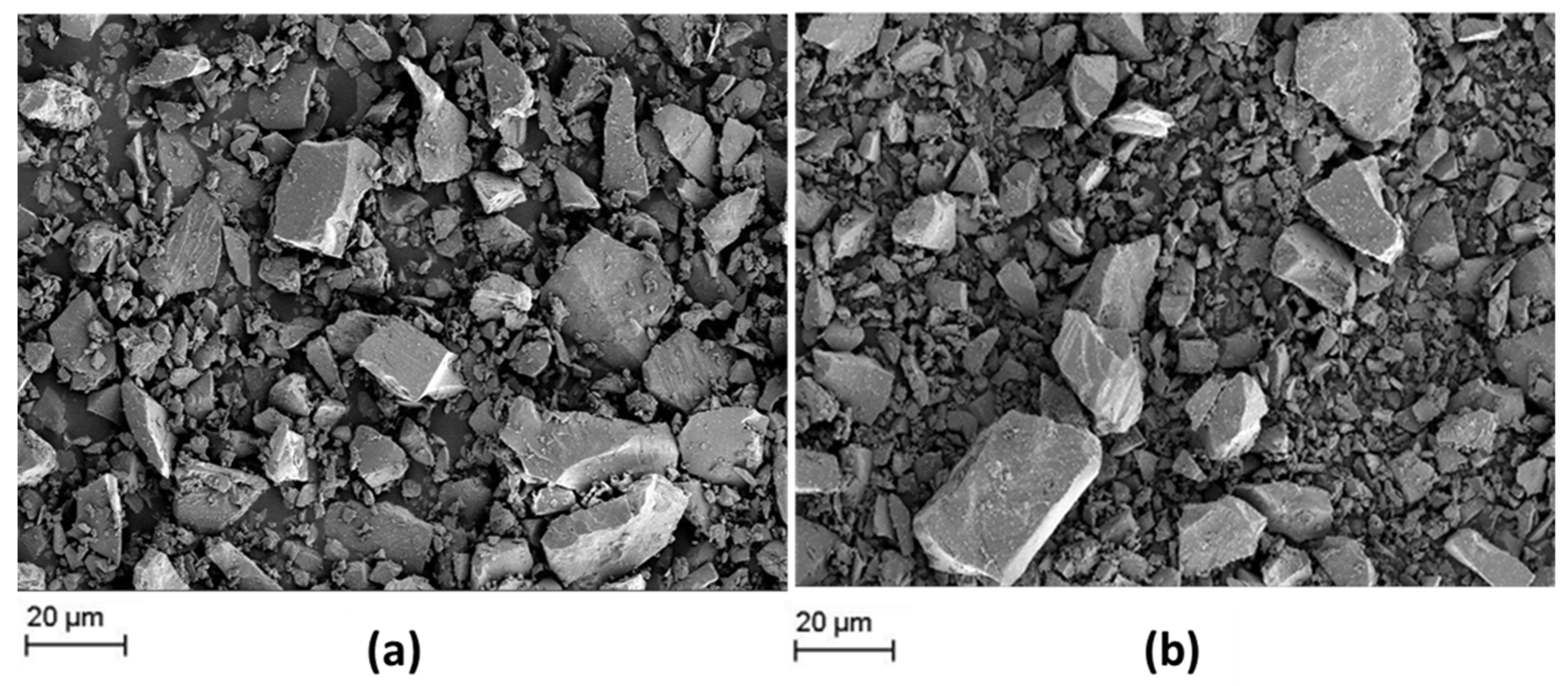
SEM micrographs of both slags in the as-received powder condition are represented in
Figure 1.
Figure 1 reveals the morphology of as-received slags after pyrometallurgical treatment in a comparative manner. Similar non-uniform microstructures and irregular chunky fragments are observed in both of the slags in the initial condition, which may be caused by the rapid cooling after the smelting process [
21]. The low element contrast of the SEM images indicates that both slags are chemically homogeneous. Moreover, both slags exhibit a broad particle size distribution from sub-micron up to 50 µm. The fraction of bigger fragments is higher in the case of slag 1. In any case, grinding/milling of as-received slags is considered necessary for processing of engineered particles.
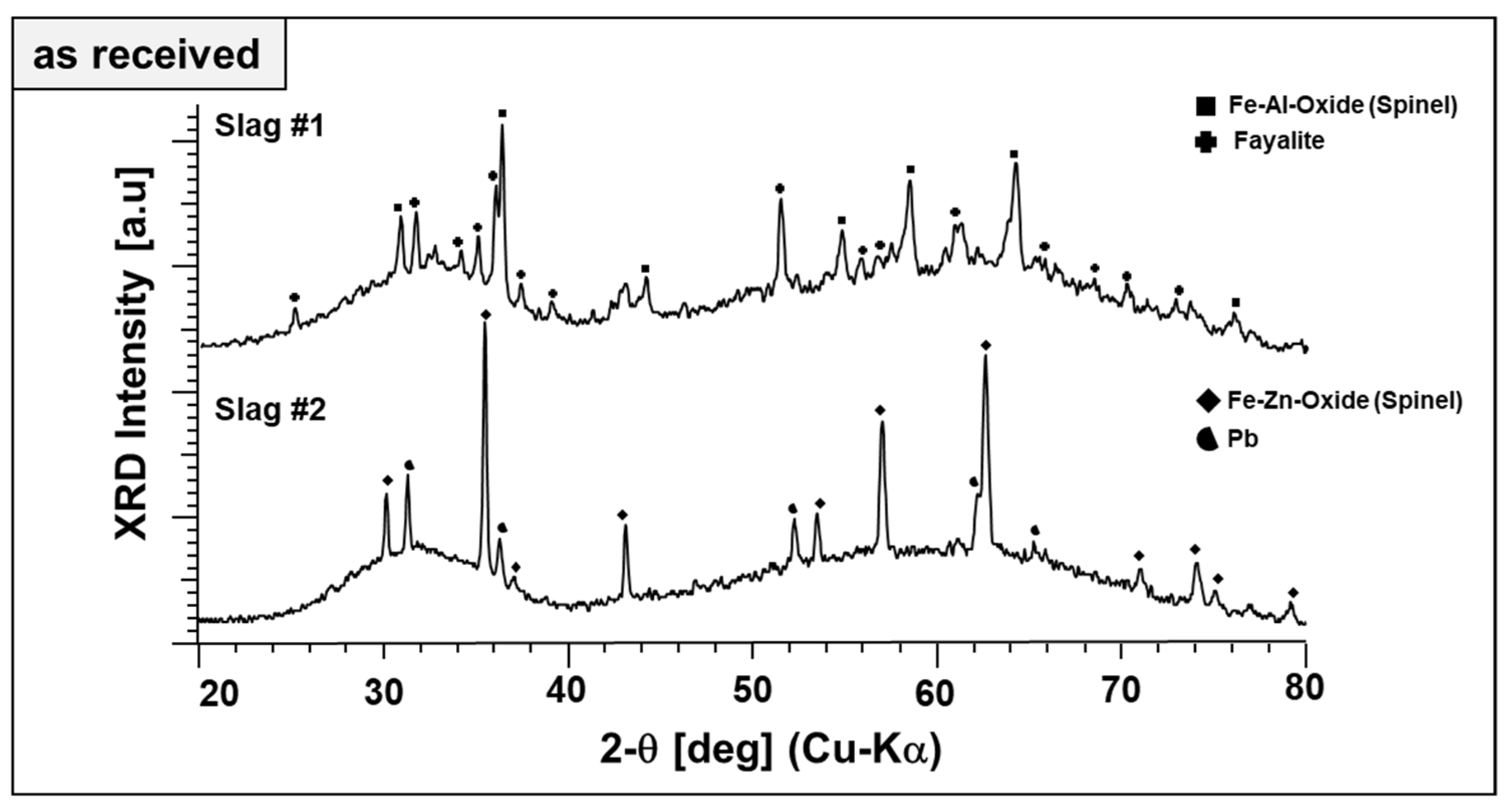
Qualitative phase analysis of the slags in the as-received form has been performed by XRD in a comparative manner, as given in
Figure 2.
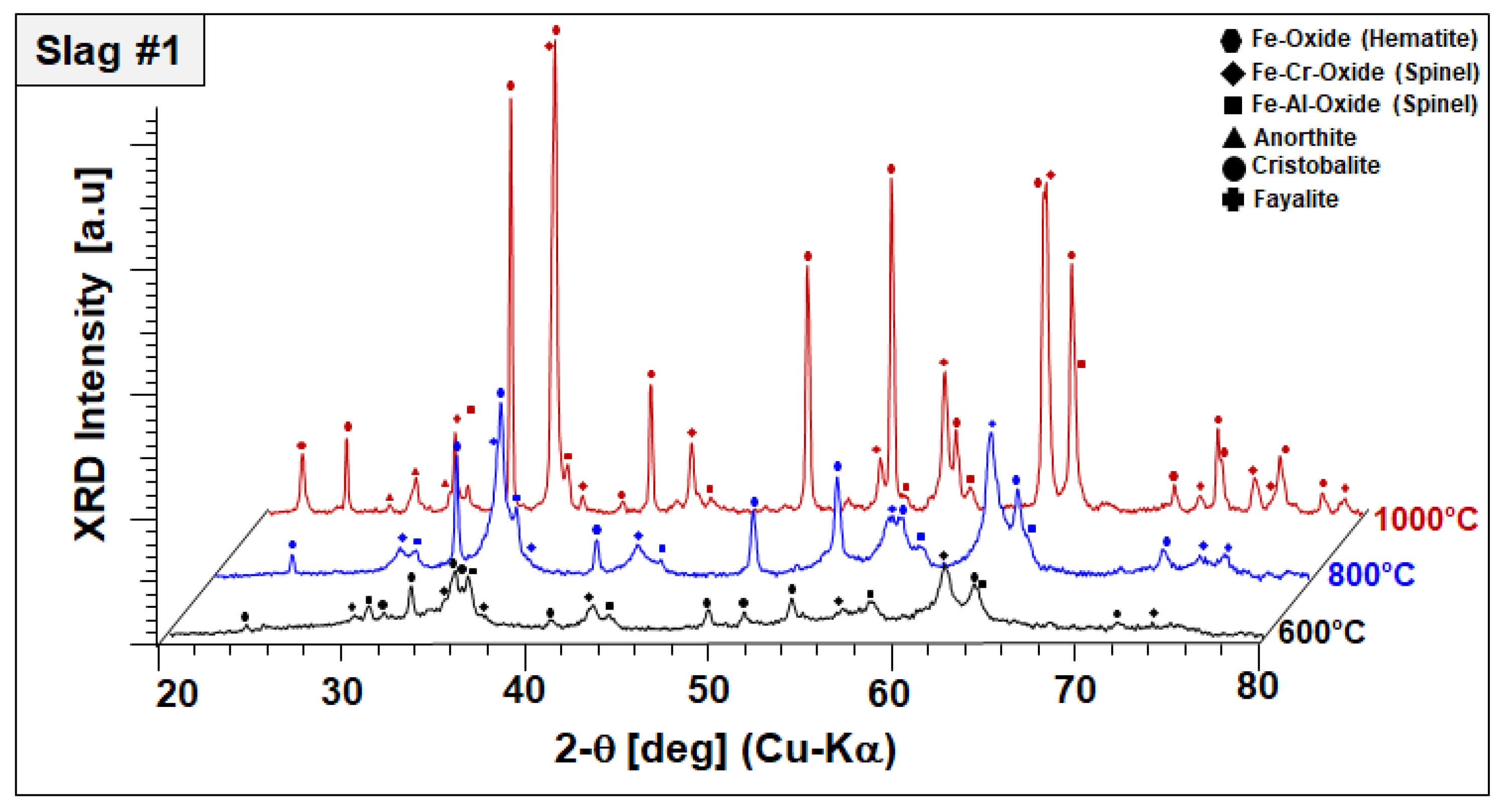
Broad diffraction humps in the XRD patterns of both slags reveal the poor crystallinity (dominant glassy, X-ray amorphous nature) of the slags. This is typical for metallurgical slags because of rapid cooling rates in the subsequent granulation step, which helps the landfilling or posterior valorization of the slags as a secondary construction material.
Figure 2 also reveals the difference in the phase content of both slags. Fayalite (Fe
2SiO
4, ICDD PDF #34-0178) is a major crystalline phase of slag 1, which is co-existing with a phase matching well the diffraction pattern and lattice parameters of a spinel-type Fe–Al oxide (FeAl
2O
4; ICDD PDF #34-0192). Similarly, the main phase component of slag 2 is matching well the spinel-type Fe–Zn oxide (ZnFe
2O
4, ICDD PDF #01-1109). Therefore, the spinels are referred to as “Fe–Al spinel” and “Fe–Zn spinel,” although their cation content most likely does not reflect the model stoichiometries. Pb (ICDD PDF #04-0686) is found as the second phase in slag 2, evidently a residuum of the smelting process. Beyond different crystalline phase components, X-ray amorphous content of the slags were estimated by Rietveld refinement. As-received slag 1 and slag 2 contain about 76 and 95 wt.% of non-crystalline phases, respectively.
3.1.2. Phase Formation at Elevated Temperatures Elucidated by XRD/STA
Varying phase components and crystallinity evidently result in different levels of thermal stability and different high-temperature behaviors of the slags. The thermal stability of slags at the operation temperature range of solar thermal plants is crucial for their applicability. Therefore, the phase formation and stability at elevated temperatures were investigated in detail.
Simultaneous thermal analyses (STA) were used to monitor the thermal evolution of slags in the temperature range of 25–1200 °C in a simulated air atmosphere (80 vol% N
2, 20 vol% O
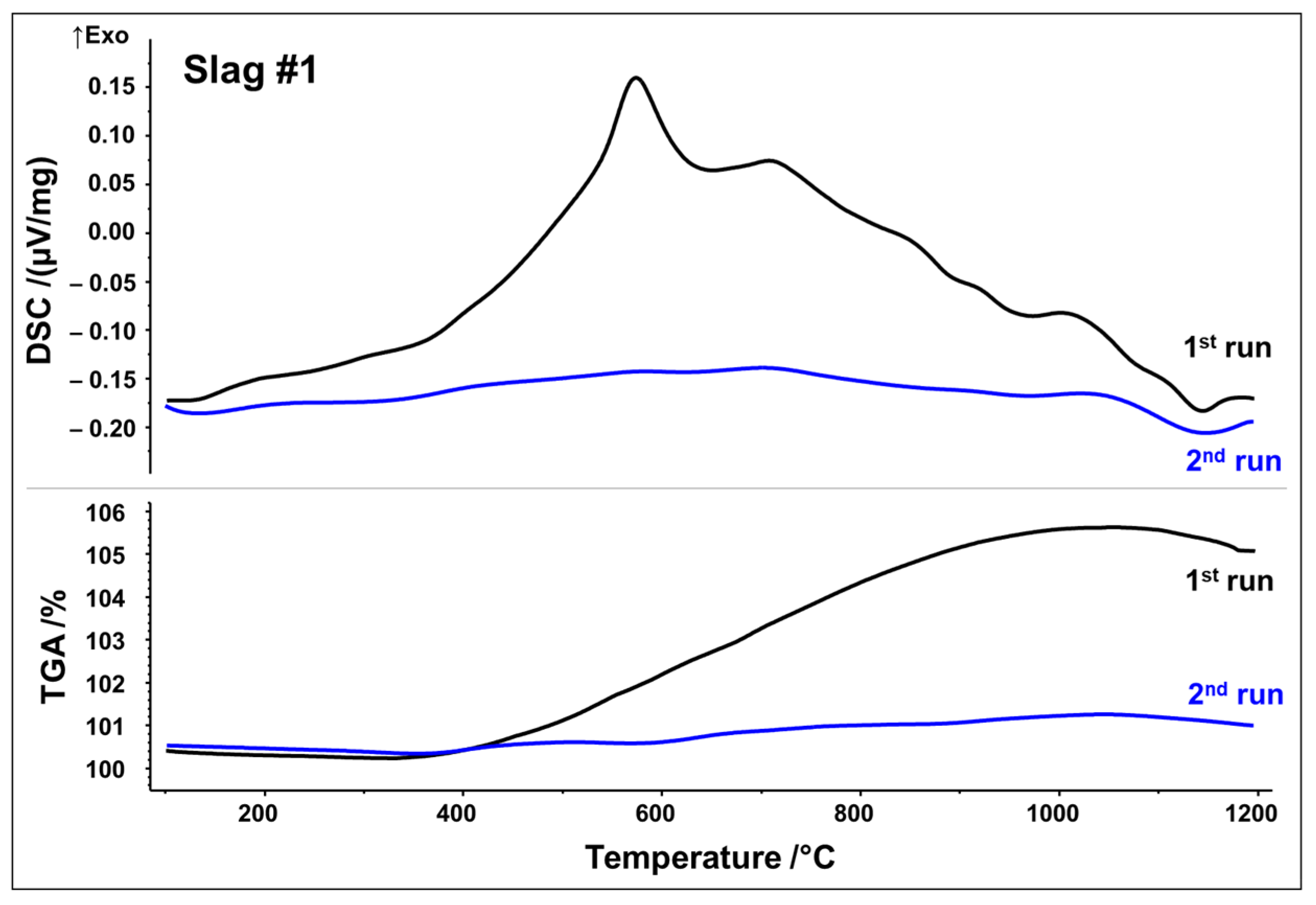
2). To capture irreversible and reversible thermal events, two subsequent runs were performed. DSC as well as thermogravimetric analysis (TGA) curves from the first and second STA runs are plotted in
Figure 3 and
Figure 4, respectively.
DSC signals reveal that both slags undergo several reactions upon first heating, which may be originating from crystallization, oxidation, and phase transformations. Slag 1 shows a relatively broad exothermic signal between 400 and 1000 °C. Superposed is a broad peak with the maximum at 575 °C, followed by a small shoulder with the maximum at 715 °C. A further exothermic event between 950 and 1050 °C can be assigned to a weak peak at 1015 °C. A small endothermic peak is observed at about 1140 °C, which could be associated with the latent heat of fusion. Simultaneously, the TGA measurement in
Figure 3 indicates a significant sigmoidal mass increase of around 5.5 wt.% during the first run in the temperature range of 400–1000 °C. (equivalent to 1.72 mol O
2 absorption per 1 kg slag). Both curves of the second STA run show way fewer features, i.e., no significant exothermic events. Only the weak endothermic event at 1140 °C seems to occur again. Considering STA measurements, it can be assumed that the broad exothermic signal as well as exothermic peaks reflect oxidation and related crystallization whereas an endothermic peak at around 1140 °C may be indicative of partial melting.
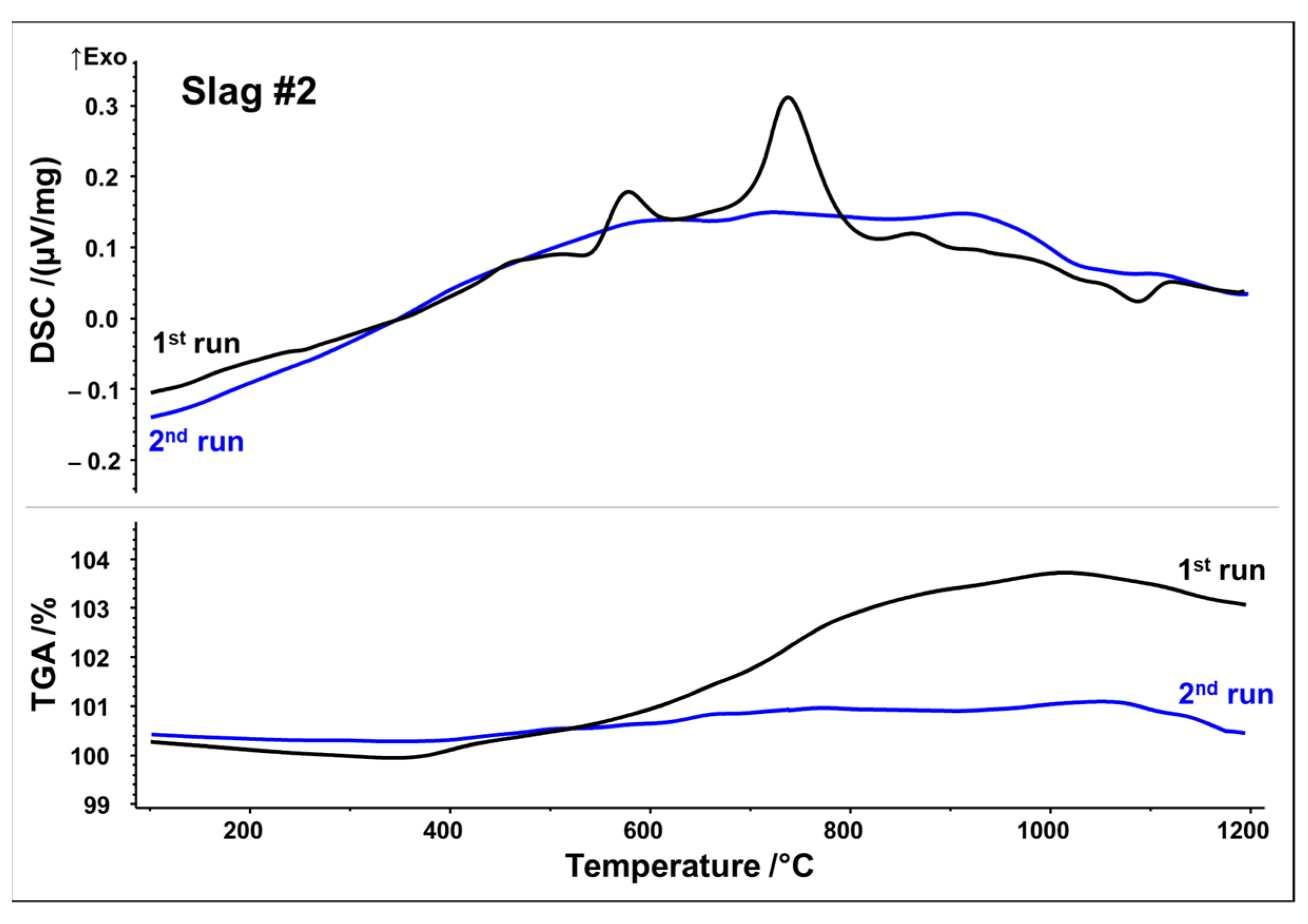
Slag 2 exhibits similar exothermic reactions with two well-defined peaks, at 580 and 740 °C. TGA analysis also reveals a substantial mass increase of around 3.8 wt.% between 400 and 1000 °C, but to a lesser extent than that observed in slag 1 (
Figure 4) (equivalent to 1.19 mol O
2 absorption per 1 kg slag). Again, it can be seen that mass increase and exothermic reactions due to the oxidation/crystallization do not take place upon second heating, implying the complete oxidation and crystallization of thermodynamically stable phases upon first heating except for a weak endothermic peak observed at 1090 °C, again indicating partial melting. It is noteworthy that both slags reach their mass gain maxima at about 1030 °C in both runs, followed by a minor mass loss up to 1200 °C. Assuming oxidation, i.e., uptake of O
2, as a source of mass gain, reduction, i.e., release of O
2, is a plausible source of the minor mass loss beyond 1030 °C.
To monitor the phase evolution taking place at elevated temperatures indicated by DSC/TGA analysis, annealed slags at 600, 800, and 1000 °C for 2 h were analyzed by XRD in a comparative manner. Annealing-temperature-dependent phase components of slags 1 and 2 are given in
Figure 5 and
Figure 6, respectively.
As a general observation,
Figure 5 reveals the disappearance of amorphous humps and peak broadenings observed in the as-received condition (see
Figure 2); both slags appear fully crystalline at 800 °C. As-received materials, which were produced by water-granulation of melts, are evidently far away from equilibrium and annealing at moderate temperatures provides sufficient activation energy and diffusion kinetics for the progressive crystallization of equilibrium phases. In slag 1, comprising fayalite and a spinel-type Fe–Al oxide in the as-received condition, the formation of hematite (Fe
2O
3, ICDD #33-0664) and a further spinel solid solution with lattice parameters close to chromite (FeCr
2O4, ICDD PDF #34-0140) were observed after sintering at 600 °C. Again, in order to discriminate this spinel phase, it is referred to as “Fe–Cr spinel” in the following although its stoichiometry will presumably incorporate all matching cations. A significant decrease in the fayalite-corresponding peaks indicates the oxidation of fayalite into those more stable phases. After sintering at 800 °C, the final phase composition does not exhibit fayalite but better crystallized hematite and Fe–Cr spinel peaks have been noticed. After sintering at 1000 °C, well-crystallized hematite, and Fe–Cr spinel were found in the structure indicated by well-defined high-intensity peaks. Moreover, the first appearance of corresponding diffraction peaks points to the crystallization of small amounts of cristobalite (SiO
2, ICDD PDF #39-1425) and anorthite (CaAl
2Si
2O
8, ICDD# 41-1486) at elevated temperatures. The initial-phase Fe–Al oxide can still be found, indicating its higher temperature stability compared to fayalite. This temperature-dependent phase evaluation points out that the peak at 568 °C observed in the DSC signal is corresponding to a fayalite-to-hematite reaction triggered by the oxidation of Fe
2+ to Fe
3+. Moreover, the formation of the Fe–Cr spinel, cristobalite, and anorthite is linked to further exothermic signals recorded up to 1000 °C.
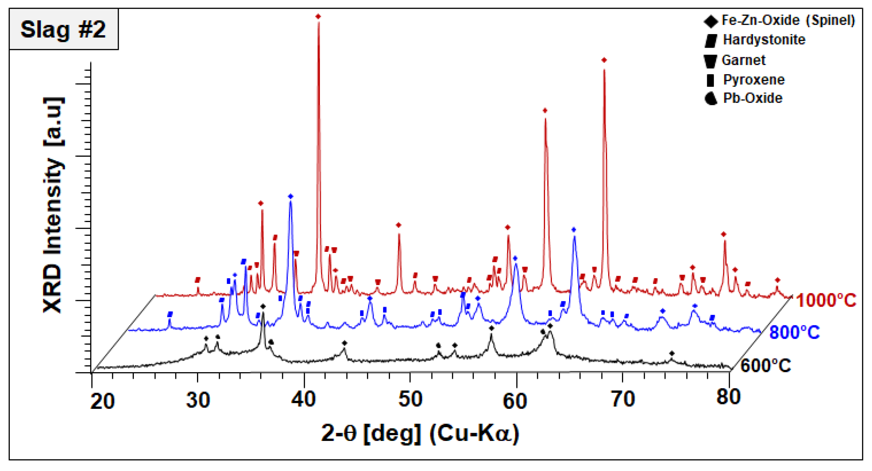
In the case of slag 2, no significant changes have been observed in the phase mixture of slag 2 after sintering at 600 °C, other than oxidation of remaining Pb droplets into Pb oxides, as represented in
Figure 6.
It should be also noted that Pb oxide exhibited poor crystal quality entailed by peak broadening and lower diffraction intensities, which may be indicating the start of its dissolution in the amorphous phase. XRD diffractograms of slag 2 sintered at 800 °C comprised of an Fe–Zn spinel with enhanced crystallinity and two newly formed phases: gehlenite-type hardystonite (Ca2ZnSi2O7, ICDD PDF #72-1603) and traces of an Fe-rich pyroxene similar to esseneite (Ca(Fe,Al)2SiO6 ICDD PDF #25-0143). When slag 2 is sintered at 1000 °C, well-crystallized Fe–Zn spinel and hardystonite are found as leading phases. At this temperature, pyroxene is not stable anymore and the formation of an andradite-type garnet phase (ICDD PDF 10-0288) is observed instead. Considering these results, it can be assumed that exothermic reactions designated by STA analysis are due to oxidation-induced, accelerated crystallization of the component Fe–Zn spinel and the formation of new crystalline phases, such as hardystonite and garnet.
Beyond XRD-assisted phase analysis, EDS analysis was performed to reveal the chemical composition of the slags in a comparative manner, as given in
Table 1.
Slag 1 in the as-prepared condition has a lower oxygen content, which prompts higher oxygen absorption rates, consistent with TGA analysis. Already by sintering at 600 °C, a significant amount of oxidation has taken place leading to hematite formation. In the case of slag 2, the initial oxygen content is relatively higher and the oxidation rate is relatively lower than those of slag 1, which is also in parallel with TGA findings. Sintering at higher temperatures does not increase the oxygen content of the slags further, implying the formation of stable phases. This was also confirmed by mass change plots reaching the steady state by 1000 °C, represented in TGA analysis.
In the light of STA, XRD, and EDS analyses, it can be concluded that slags with a complex phase structure and poor crystallinity can be converted into the thermally stable phase components with enhanced crystal quality by irreversible oxidation, which promotes their use in high-temperature solar energy applications.
3.1.3. Slag Modeling
Several studies have been carried out on fayalitic slags due to their importance in non-ferrous metallurgy because the reaction between Si and Fe prevents the reduction of iron during the pyrometallurgical process [
22,
23,
24]. Fayalite is a compound that is only stable at high temperatures for oxygen partial pressures lower than 10
−10 bar, which evidences that oxygen partial pressures and chemical composition play a central role in the physical properties of these slags [
22,
25,
26].
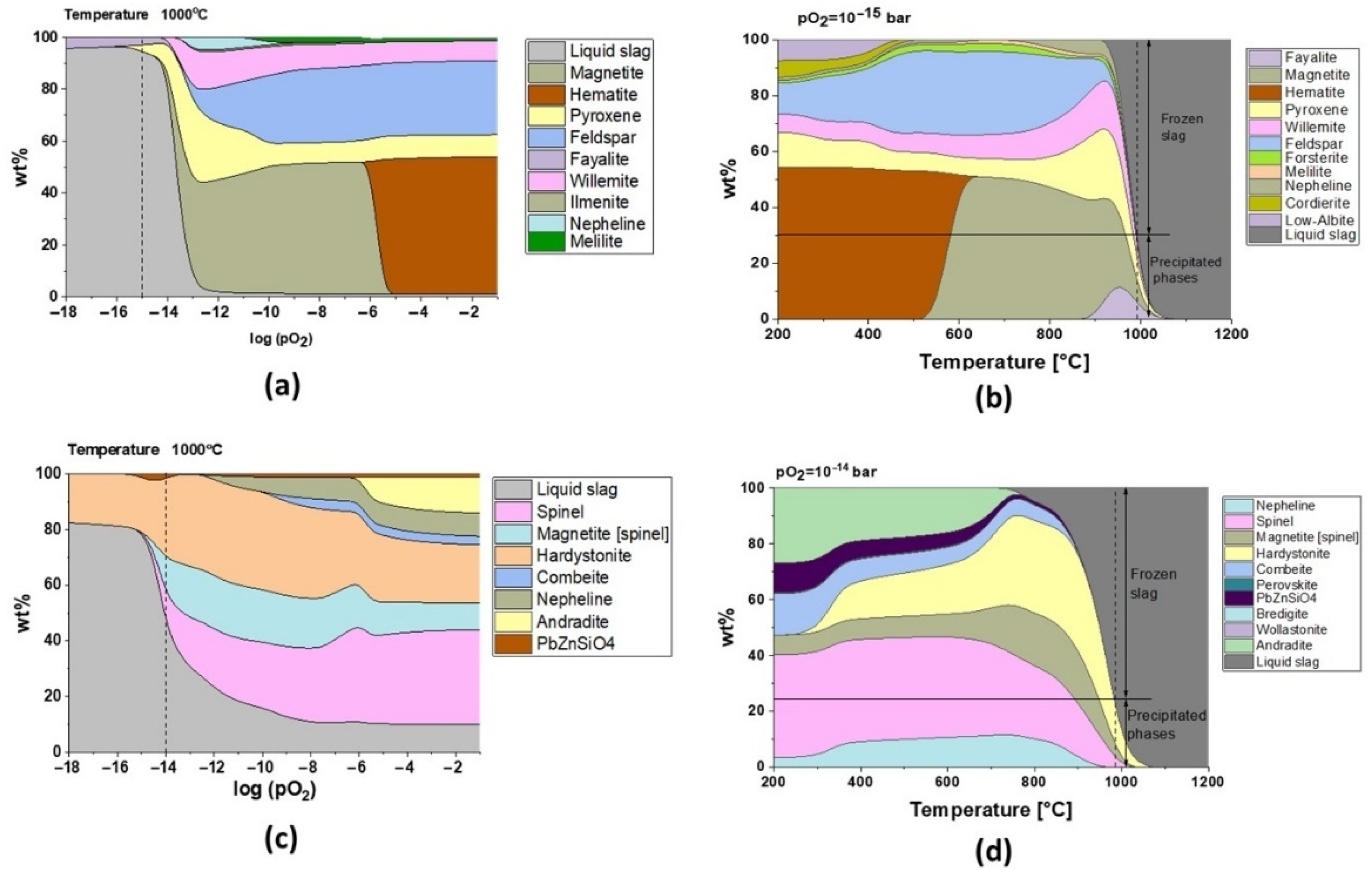
Regarding the chemical composition of the slags in the as-received condition (
Table 1), models carried out with FactSage showed that fayalite phases are present at high temperatures only for the oxygen partial pressure lower than 10
−13 bar in the case of slag 1 (
Figure 7a). However, modeling predicts that there will not be any fayalite precipitation for slag 2 (
Figure 7c). The phase analysis of the as-received slags (
Figure 2) and the TGA-DSC results (
Figure 3 and
Figure 4) serve to understand the industrial conditions of these slags.
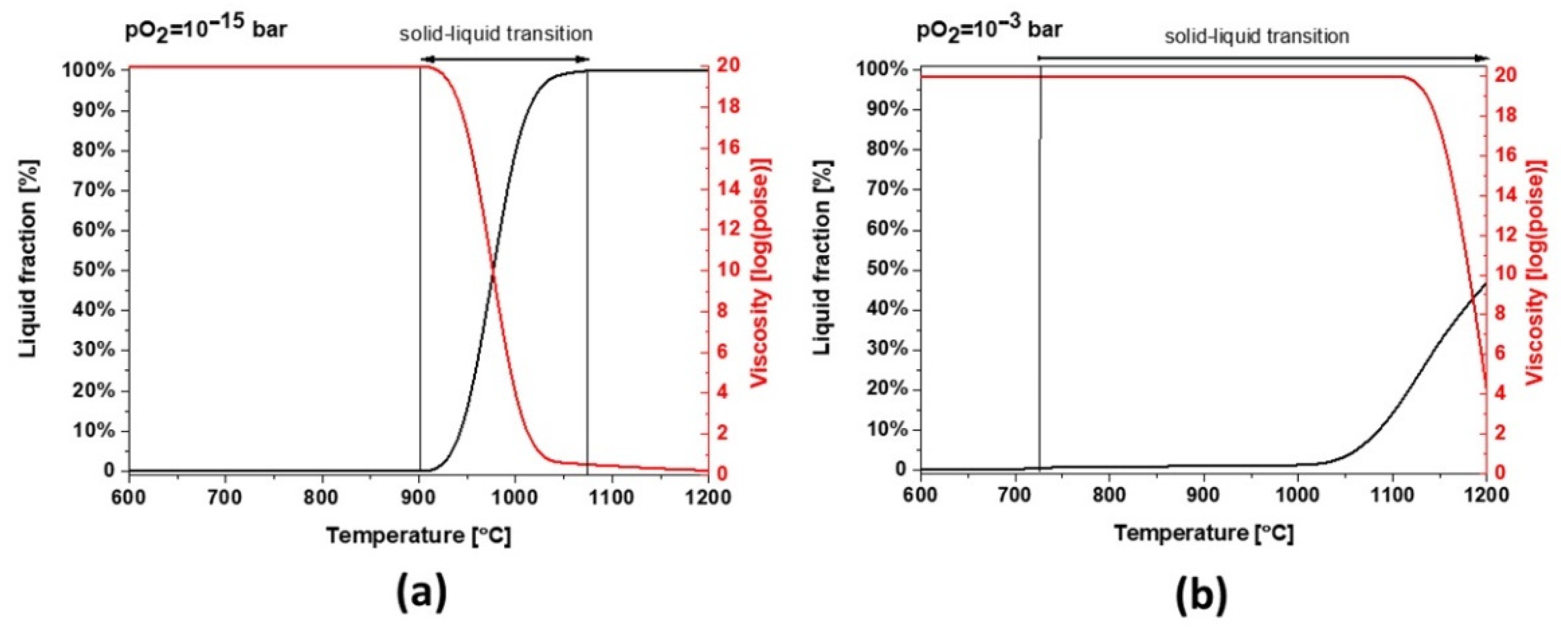
The presence of fayalite and ferric spinel phases in slag 1 shows that the smelting process took place with pO
2 of 10
−15 bar, and the model for this oxygen partial pressure in
Figure 7b exhibits that water granulation froze the slag structure at around 1000 °C, transforming 70% of the remaining liquid into a glass phase, which is in good accordance with the 75 wt.% amorphous content calculated by the Rietveld method.
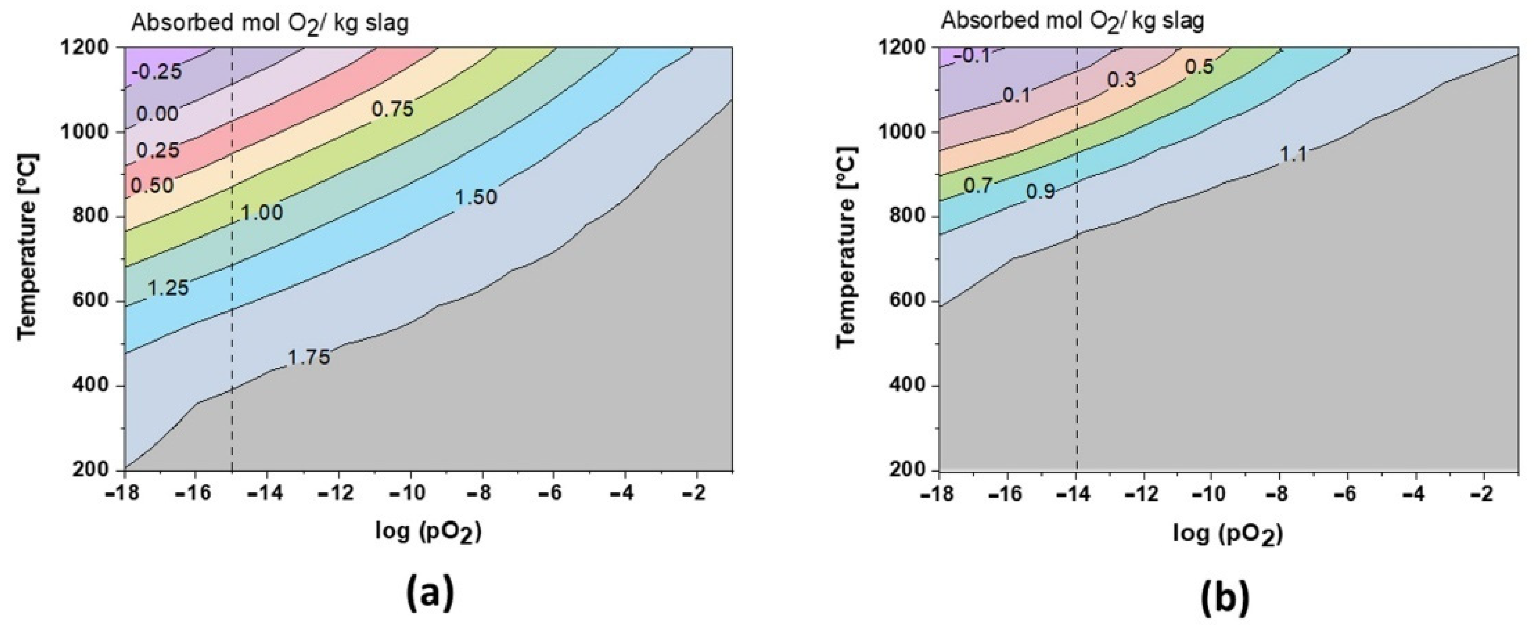
The role of oxygen has been the key to understand the formation of the crystalline phase. As shown in
Figure 8, during cooling at equilibrium conditions, the slags can theoretically absorb up to 1.8 mol and 1.15 mol O
2 per kg of slag 1 and slag 2, respectively. These values are also in perfect correlation with TGA results, where the amorphous, fayalite, and magnetite-type spinel phases are fully oxidized during annealing. Close to the slag melting point, the oxidation behavior is inverted and the slags re-release oxygen (see
Figure 3 and
Figure 4). Due to its amphoteric characteristic, iron is leading this oxygen absorption/release behavior at high temperatures, varying with Fe
2+/F
3+ species. Regarding slag 2, the oxidation exceeds theoretical limits, which could be explained by the oxidation of Pb droplets trapped in the slag, as shown in
Figure 2. This oxidation is also reported by the XRD profiles between 600 and 1000 °C in
Figure 6.
It can be appreciated that oxygen controls the microstructure and the melting point of fayalitic slags if the temperature is fixed and the model is studied regarding the influence of oxygen partial pressures as shown in
Figure 7a and c for slag 1 and slag 2 at 1000 °C, respectively. Each cycle of cooling and heating in air/oxygen atmosphere will gradually move the equilibrium to full oxidation where hematite and spinel phases are stable at high temperatures, and thus slags become more refractory due to an increase in their melting points.
Slag 1 exhibits hematite as the dominant phase without the co-existing amorphous phase, as confirmed in XRD diffractograms after sintering at high temperatures (see
Figure 5), which is only possible for fully oxidized samples (see
Figure 7a for pO
2 higher than 1·× 10
−5 bar). This oxidation also explains why slag samples do not release the same oxygen amount at high temperatures during the second heating STA cycle (see
Figure 3). According to the modeling of melting point and viscosity, at industrial condition, slag 1 presents a narrow liquid/solid transition between 900 and 1075 °C with a fast drop in viscosity (see
Figure 9a). For a higher oxidation state, the liquid/solid transition is expanded perhaps physically as a formation of amorphous phases around spinel and hematite crystals where the melting point is far beyond 1200 °C.
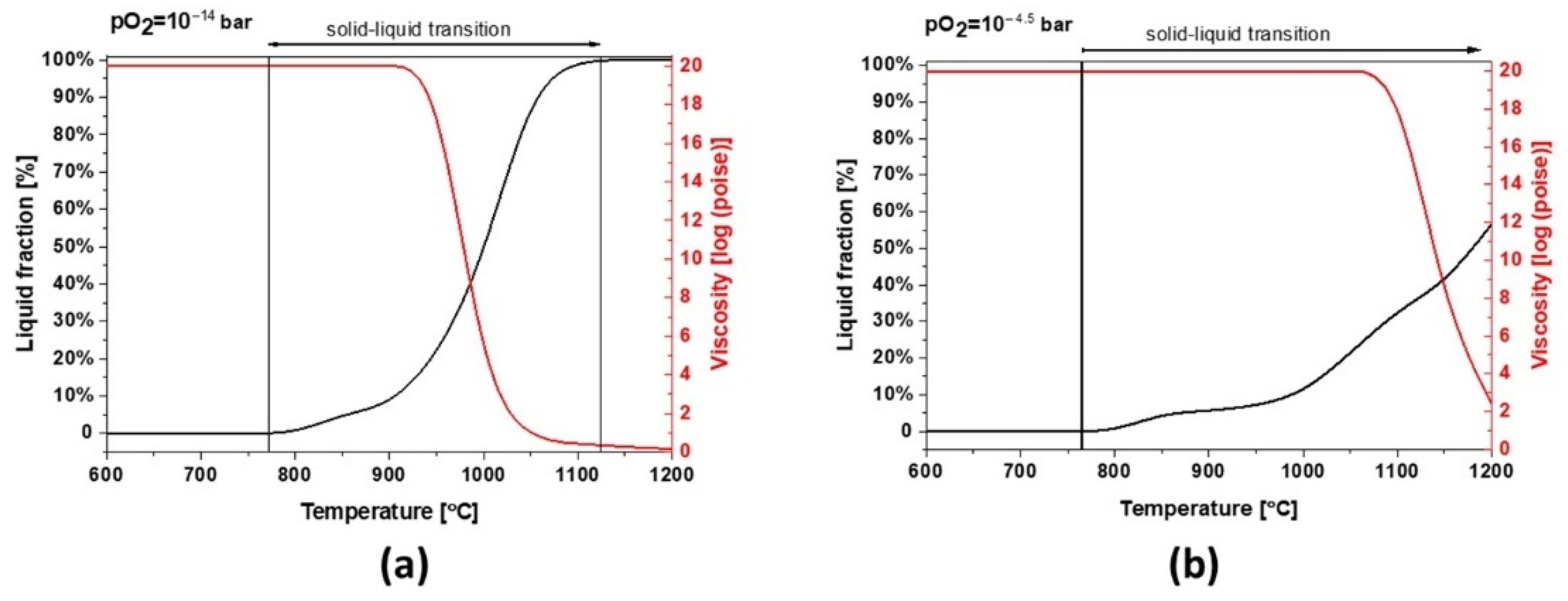
Slag 2 depicts a similar behavior to slag 1. However, due to its different chemical composition, mainly a lower content of Fe, this sample can absorb less oxygen and the slag exhibits a broad solid–liquid transition and a higher melting point at industrial conditions (see
Figure 10a). As shown in
Figure 10b, the melting point increases under more oxidative conditions but the formation of liquid/glassy phases is several times higher than slag 1, comparing the temperature range of 800–1000 °C, which is also consistent with the calculated 95 wt.% amorphous content obtained by Rietveld profile fitting. These wide transition ranges can be physically translated into more significant glassy phases and a completely different dilatation and thermal behavior.
3.1.4. Preparation and Assessment of Slag-Derived Particles for Solar Thermal Processes
After the analyses of slags’ material properties and high-temperature behavior, the solar energy absorber particle candidates were prepared by the oil dropping method, with a diameter around 1 mm, similar to that of commercial absorber particles. To determine the optimum sintering temperature to achieve dense particles before they reach their melting temperature, a heating microscope was used.
Heating Microscopy
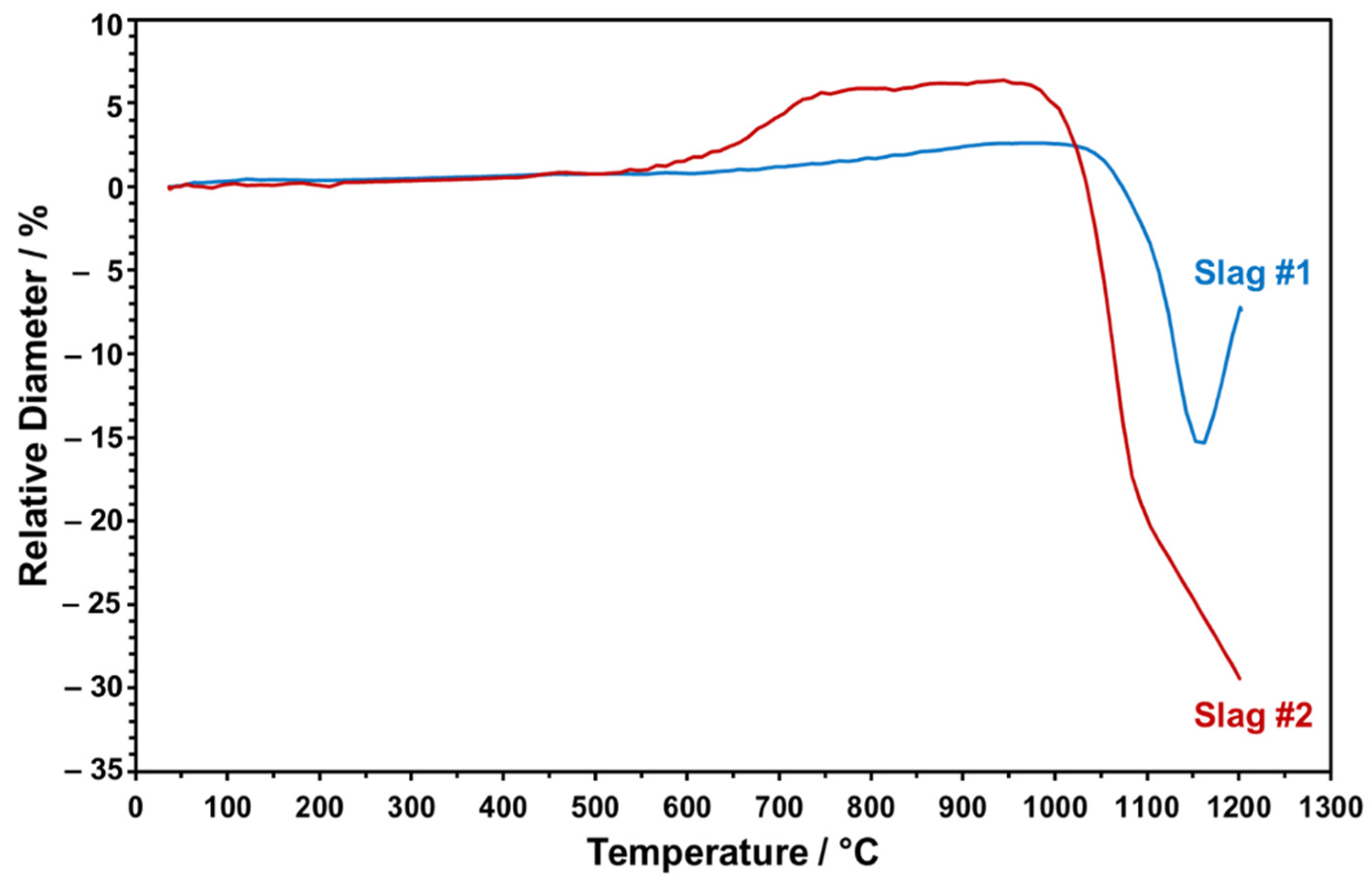
The dropped particles were heated from RT to 1200 °C to monitor in situ shape changes taking place during the sintering. The relative height of the slag particles was evaluated as a function of increasing sintering temperature in a comparative manner, as given in
Figure 11.
Figure 11 points to the distinct trend of relative height change for both slag particles upon heating up to 1200 °C. The onset temperature of sintering for slag 1 is around 1050 °C. Heating above 1150 °C causes a sudden volume increase, which may be due to the partial melting and blow up of the more viscous, SiO
2-rich, slag, which has been also indicated in the FactSage model and STA analysis. Since partial melting at this stage may result in undesired bubbles in the particles, the maximum sintering temperature has been determined as 1150 °C for slag 1. In the case of slag 2, sintering starts earlier, at around 950 °C, as can be seen in
Figure 11. As the temperature reaches a value above 1100 °C, due to the melting of the slag particle and progressive wetting of the sample holder with low viscosity, relative SiO
2-lean melt is detected in the dilatometer experiment. Therefore, 1100 °C is determined as the maximum feasible sintering temperature for slag 2 to ensure densely sintered particles in conserved spherical form. Here, it is also worth mentioning that slag 2 exhibited an obvious height increase around 650 °C, which may be due to decomposition of Pb oxide and consistent with the FactSage model and STA/XRD analyses (see above).
Phase and Microstructural Analysis of Sintered Particles
In
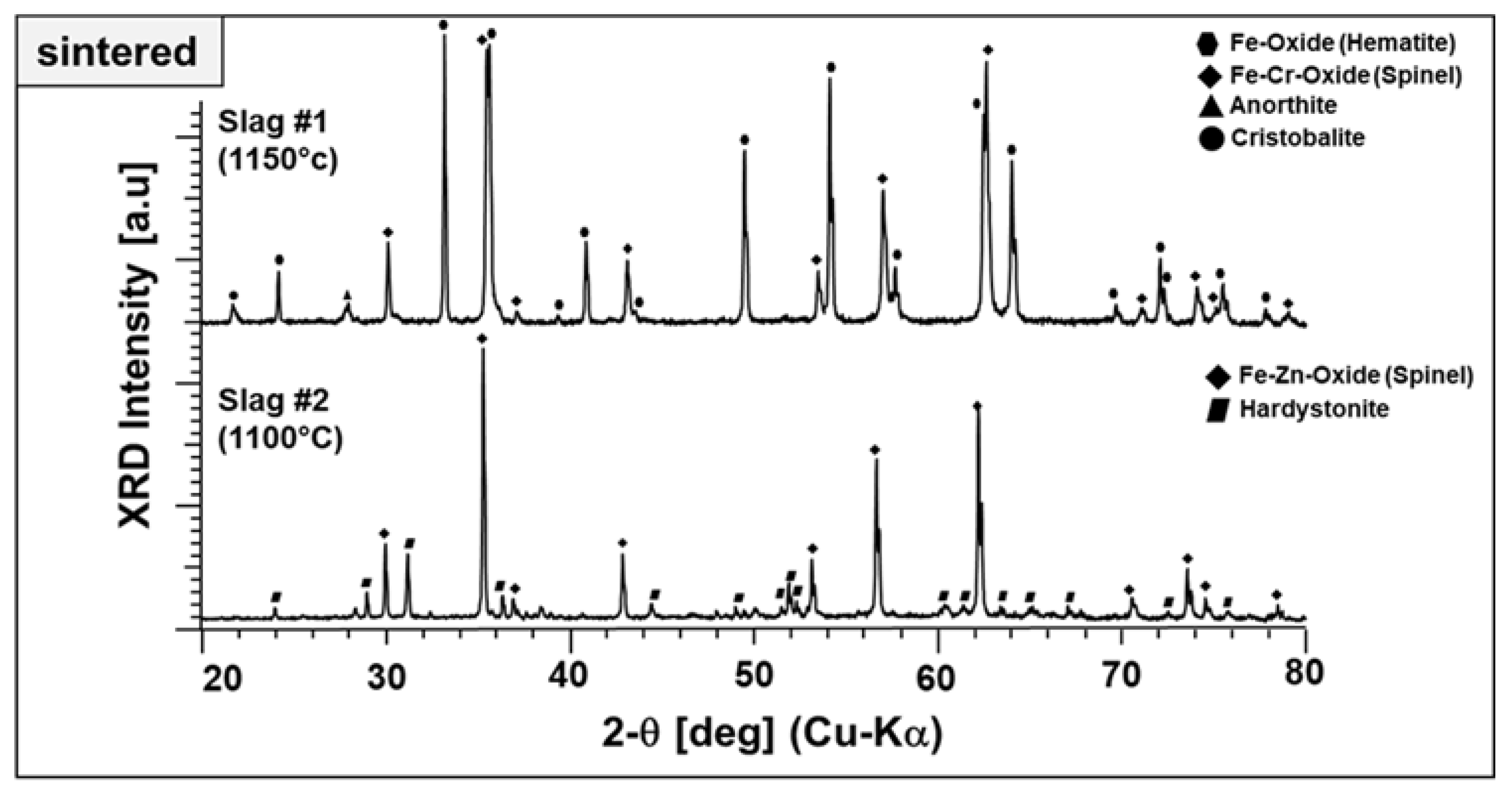
Section 3.1.2, we performed a parametric study regarding the phase components at elevated temperatures up to 1000 °C. However, in the light of optical dilatometry results, higher temperatures than 1000 °C were applied for the sintering of slag particles to ensure well-consolidated end products. Therefore, slag 1 particles and slag 2 particles were also investigated after sintering at 1150 and 1100 °C in terms of their final phase mixture, as given in
Figure 12.
Both particles produced from slags exhibit a well-crystalline nature with narrow and high-intensity diffraction peaks. The end product derived from slag 1 comprises mainly hematite, which is Fe–Cr spinel accompanied by anorthite and cristobalite. Here, it is worth highlighting that the Fe–Al spinel, one of the starting phase components stable after sintering at 1000 °C (see
Figure 2), is no longer present at this temperature. It may be diffused into Fe–Cr spinel and/or decomposed to hematite. Moreover, the presence of two different stable ferric phases may be due to the relatively high Fe content in the as-received condition and may be beneficial for the absorption properties.
Figure 12 also represents the end product of slag 2, which comprises Fe–Zn spinel and hardystonite. The intermediate compounds, garnet and pyroxene, which appeared at around 800 and 1000 °C, are not stable at elevated temperatures. No crystalline Pb-containing phases have been detected. There are some low-intensity peaks located at ~32, 38, and 48 degrees, which could not be identified and may be corresponding to a phase containing Pb.
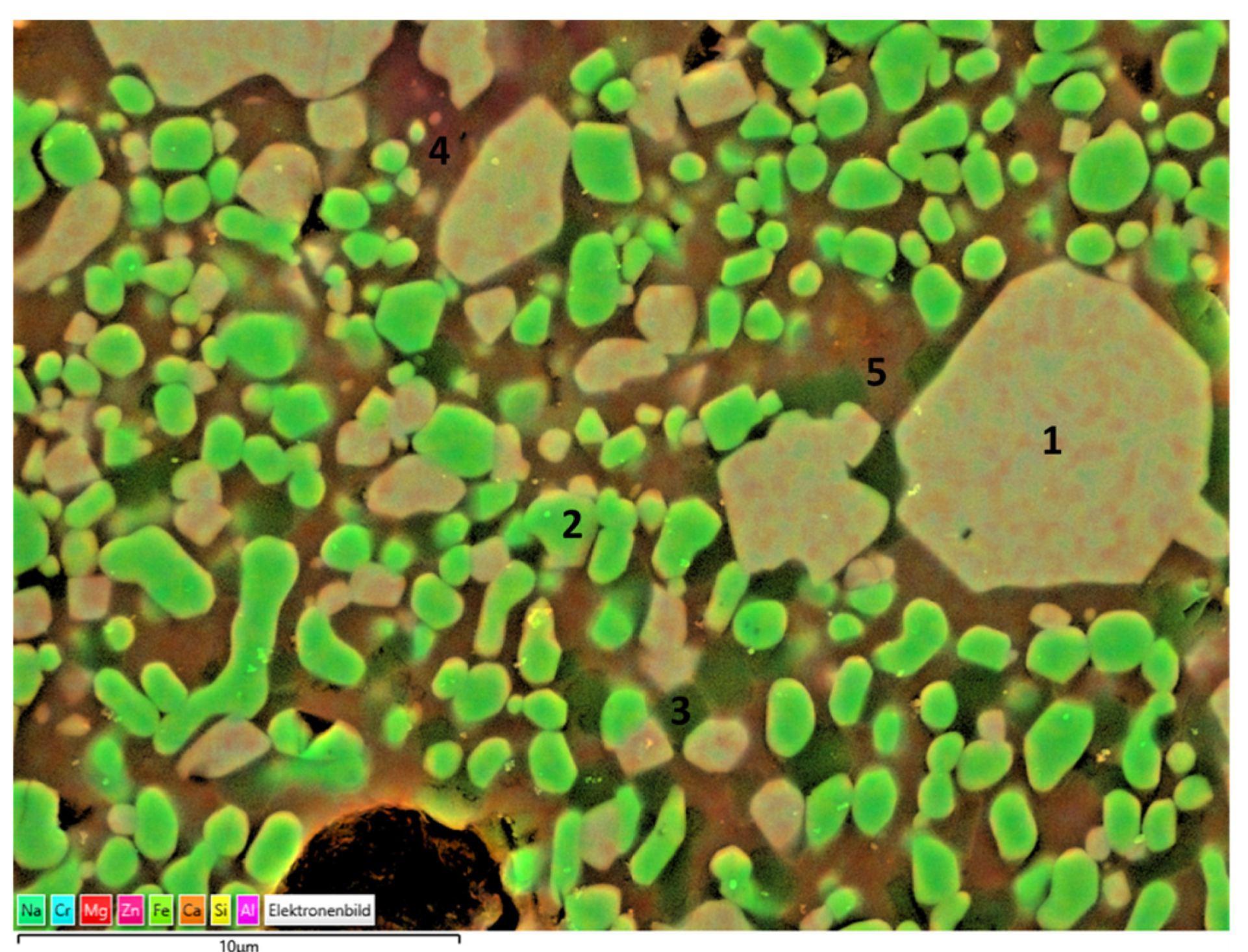
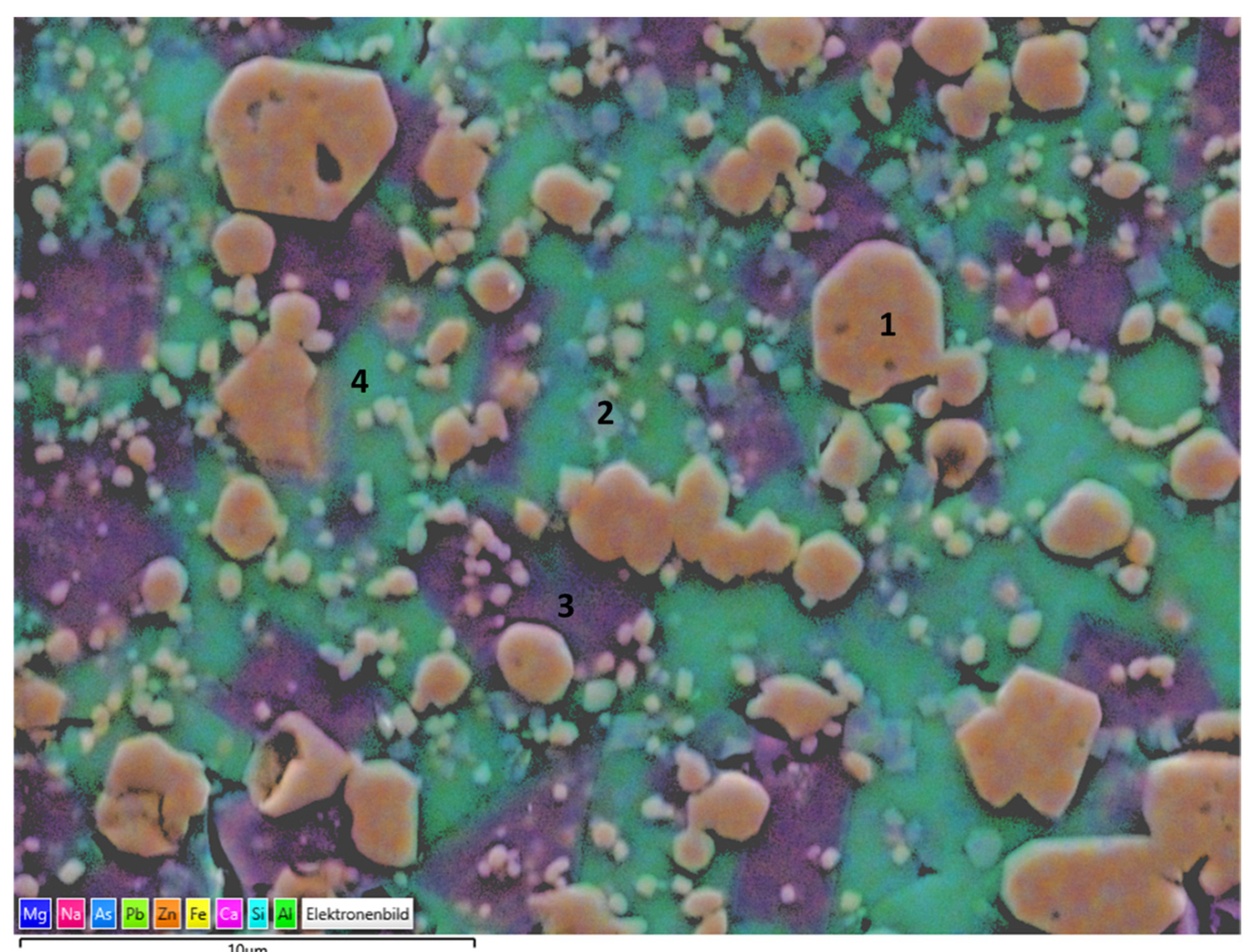
Slags have a complex mineralogy and phase components in the as-received state as well as after sintering. There may be some remaining less crystallized and glassy parts that cannot be detected by XRD. Therefore, end products prepared from slags were also analyzed by SEM and EDS, as given in
Figure 13 and
Figure 14, respectively. Corresponding phase components of slag 1 particles sintered at 1150 °C and slag 2 particles sintered at 1100 °C as given in
Table 2 and
Table 3, respectively.
Consistent with the XRD findings, the main crystal phases were determined as Fe–Cr oxide encapsulating certain amounts of Zn, Al, Mg, and hematite, as can be seen in the particles labeled as 1 and 2, respectively. The darker crystals embedded in the matrix and labeled as 3 may be corresponding to cristobalite in parallel with XRD findings. Moreover, the region labeled as 4 exhibits high Al and Ca content with a stoichiometry similar to that of the anorthite crystals, revealed also in XRD analysis. The surrounding green matrix, as in point 5, corresponds to the glass phase with a lack of crystallinity entrapping Fe, Si, Zn, Al, Mg, Na, and Ca.
Slag 2 particles exhibited a similar microstructure with a glassy matrix and Fe including crystals. Consistent with XRD findings, as the main phase, Fe–Zn particles labeled as 1 were detected. Moreover, hardystonite crystals were also confirmed, as can be seen in the region labeled as 2. A significant amount of surrounding glassy matrix was observed in the case of slag 2 particles and exhibited two different compositions, labeled 3 and 4, respectively. The former is rich in terms of Ca, and the latter is in terms of Pb, which indicates as revealed by XRD findings that after the decomposition of PbO, Pb was integrated into the glass phase structure.
Thermal-Mechanical Properties
Polished cross sections of slag particles were also used to measure the Vickers hardness by the indentation method. Hardness is considered a suitable indicator for abrasion resistance of cold particles during bulk transportation/feeding. The average hardness of 10 measurement points was determined as 663 and 530 HV for slag 1 and slag 2, respectively. The higher hardness of slag 1 is presumably due to the lesser glass phase content, as also revealed by SEM analysis (
Figure 13), and comparable with the hardness values of the commercial ceramic particles used in the solar receiver applications [
6,
8].
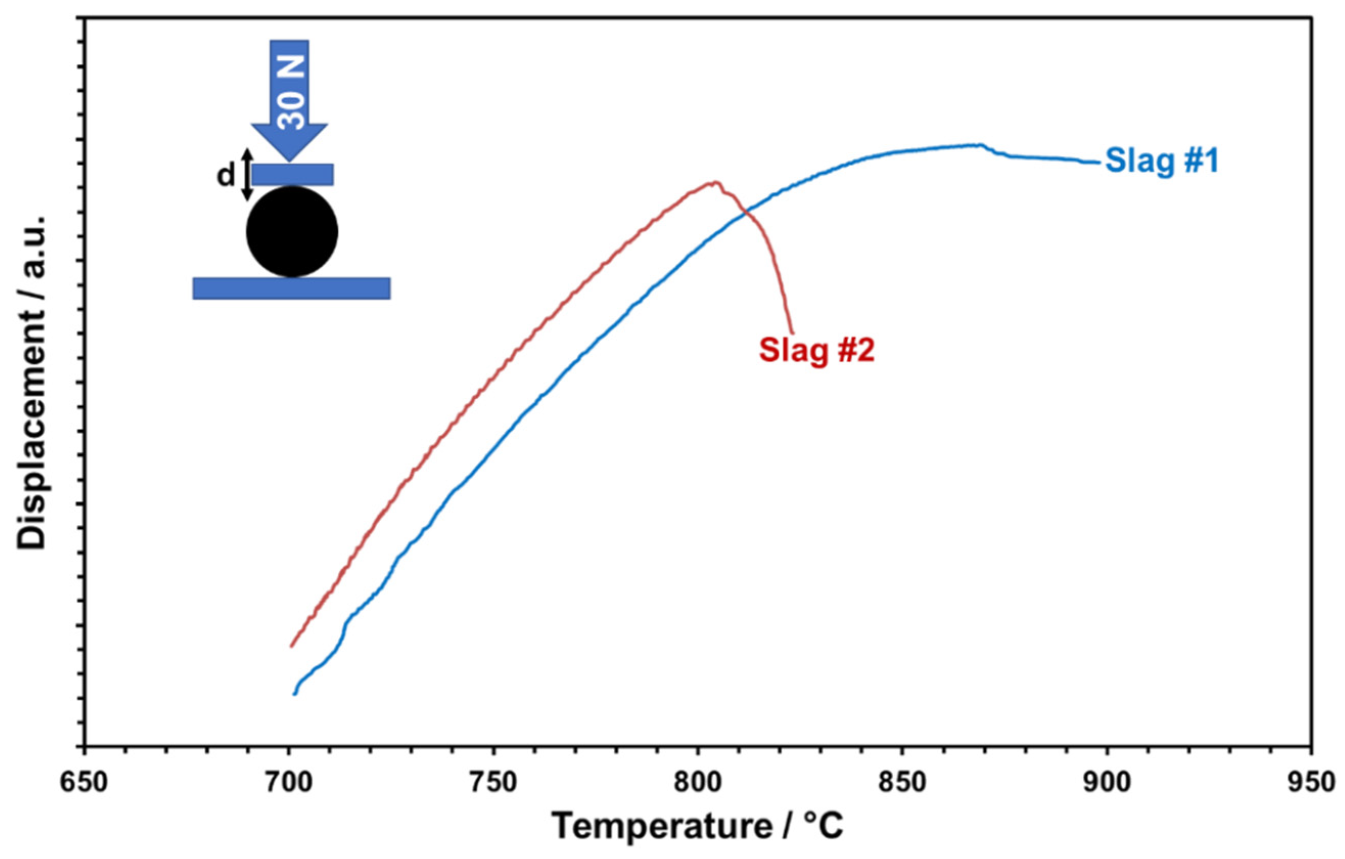
The glassy phase content of the particles is considered relevant for the softening and viscous flow of the particles, which may result in poor shape stability and also the sticking of particles at elevated temperatures supposed to be reached in CSP plants. In particular, in storage containers, particles are piled up and, depending on their position, face substantial isostatic forces. To mimic this scenario qualitatively and determine critical temperatures, the high-temperature compression behavior of single particles was tested. For this, particles were uniaxially loaded with a controlled force of 30 N and the temperature-dependent cross-head displacement was recorded (
Figure 15). Both slags show a linear displacement first, which is evidently due to linear thermal expansion only. A significant deviation from linearity is observed for slag 1 at about 740 °C and for slag 2 at about 720 °C. This “creeping” indicates the initial softening of particles, presumably caused by glass transition or even partial melting of amorphous phases. Mechanical destabilization by bulk softening is indicated by an abrupt loss of applied pressure and dropping displacement curves. Whereas slag 1 retains some stability up to about 870 °C, slag 2 abruptly softens at about 805 °C. The higher thermal-mechanical stability of slag 1 is owing to the more stable phase components with a less glassy matrix, comparable with the values of commercial particles [
27].
Optical Properties
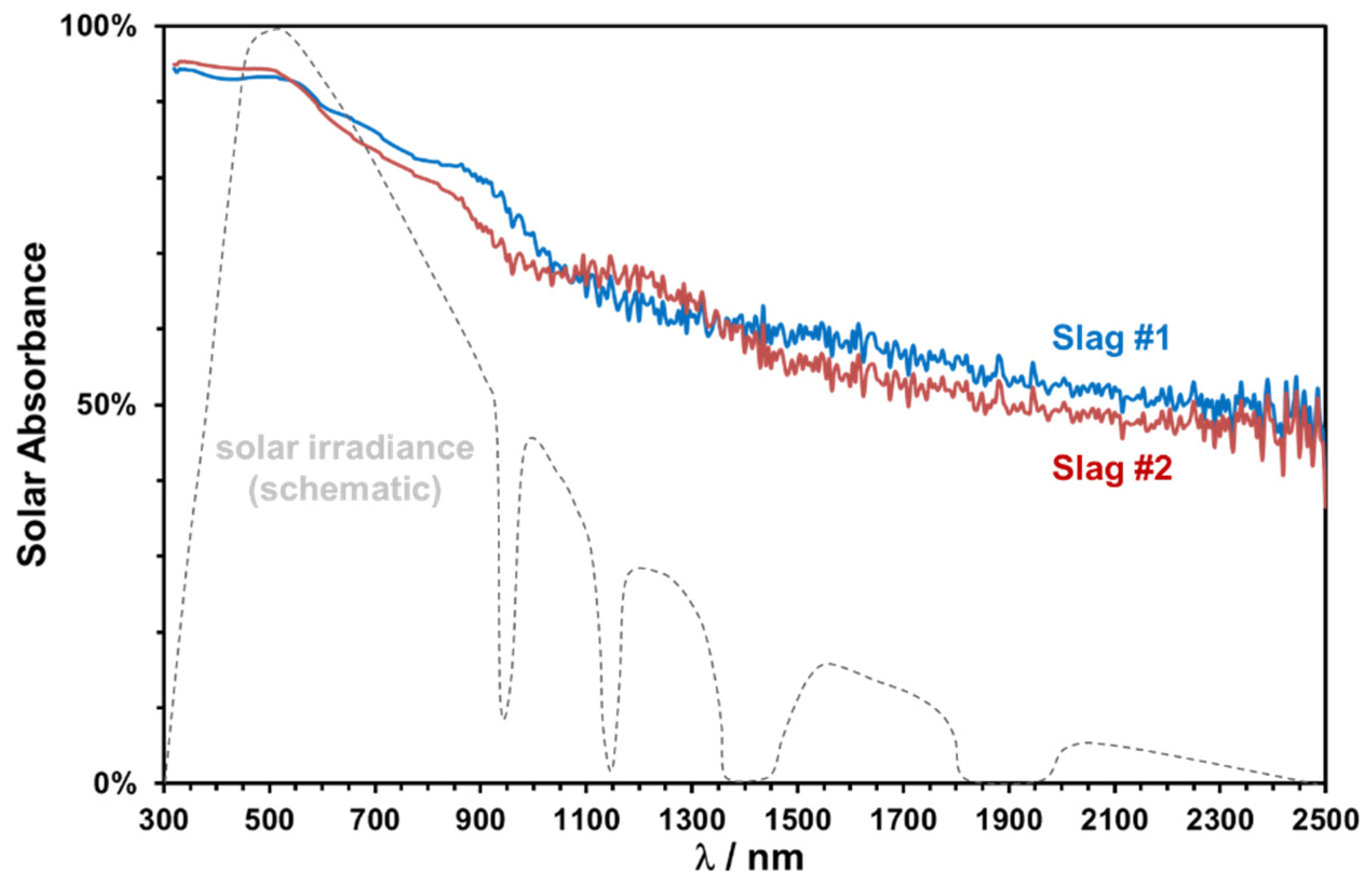
The absorptance spectra in the range of 320–2000 nm of two slags sintered at 1000 °C for 2 h are plotted in
Figure 16, along with a schematic representation of the normal solar irradiance. Both slags exhibit a good absorptance in the important spectral range between 400 and 900 nm.
The solar weighted absorptance has been calculated according to ASTM 173d standards as 0.81 and 0.79 for slags 1 and 2, respectively. The slightly higher absorptance of copper slags is consistent with their relatively higher Fe content and darker coloring. A significant decrease at higher wavelengths is observed, which can be modified easily by pigment addition or can be used as selective lower absorption in the near-infrared region to reduce the emission losses [
19].
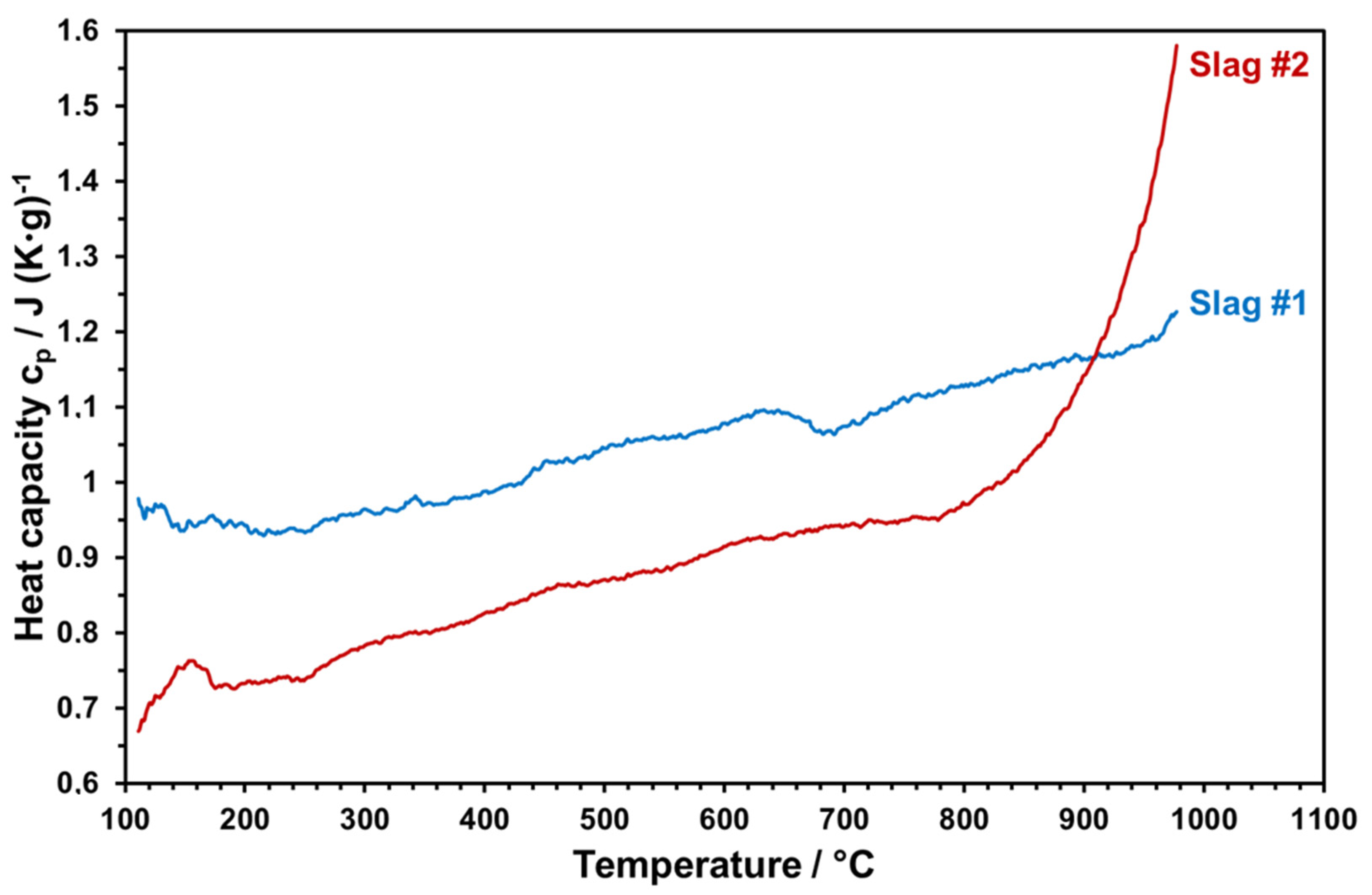
Heat Capacity
Temperature-dependent heat capacities of both slags sintered at 1000 °C were measured within 3 cycles up to 1000 °C. The measured values were averaged and plotted as given in
Figure 17.
Heat capacity is an important property to ensure enhanced storage densities.
Figure 16 reveals that slag 1 reaches up to 1.2 J/g-K at elevated temperatures, which is highly promising and comparable with the commercial solar absorber particles [
6,
8]. At each temperature, slag 2 has a lower heat capacity with respect to slag 1. Starting from 800 °C, there is a sharp increase in the heat capacity of slag 2 due to the partial melting of slag 2. The same behavior can be seen from optical dilatometry results (
Figure 11) and in the FactSage model, which can have a negative influence on the stability of slag particles by continuous thermal cycling. Therefore, the maximum application temperature of slag 2 can be considered as around 800 °C. The high heat capacity and the thermal stability of slag 1 make it a better candidate for solar heat storage. This comparative incipient study indicates the potential use of copper slags as raw materials for engineered particles as solar heat transfer and storage mediums. However, due to the heterogenous nature of metallurgical slags, which may vary even from sample to sample of the same batch, properties presented in this work should be considered only as a trend; large-scale particle production and application will require examination of different raw material sources and possible definition of a compositional window to ensure reproducible functional properties as well as optimized and stable production parameters.


 ,
, 


