
Hydrodynamic Hysteresis and Solute Transport in Agglomerated Heaps under Irrigation, Stacking, and Bioleaching Controlling


Abstract
:1. Introduction
2. Materials and Methods
2.1. Ore Samples and Its Agglomeration Condition
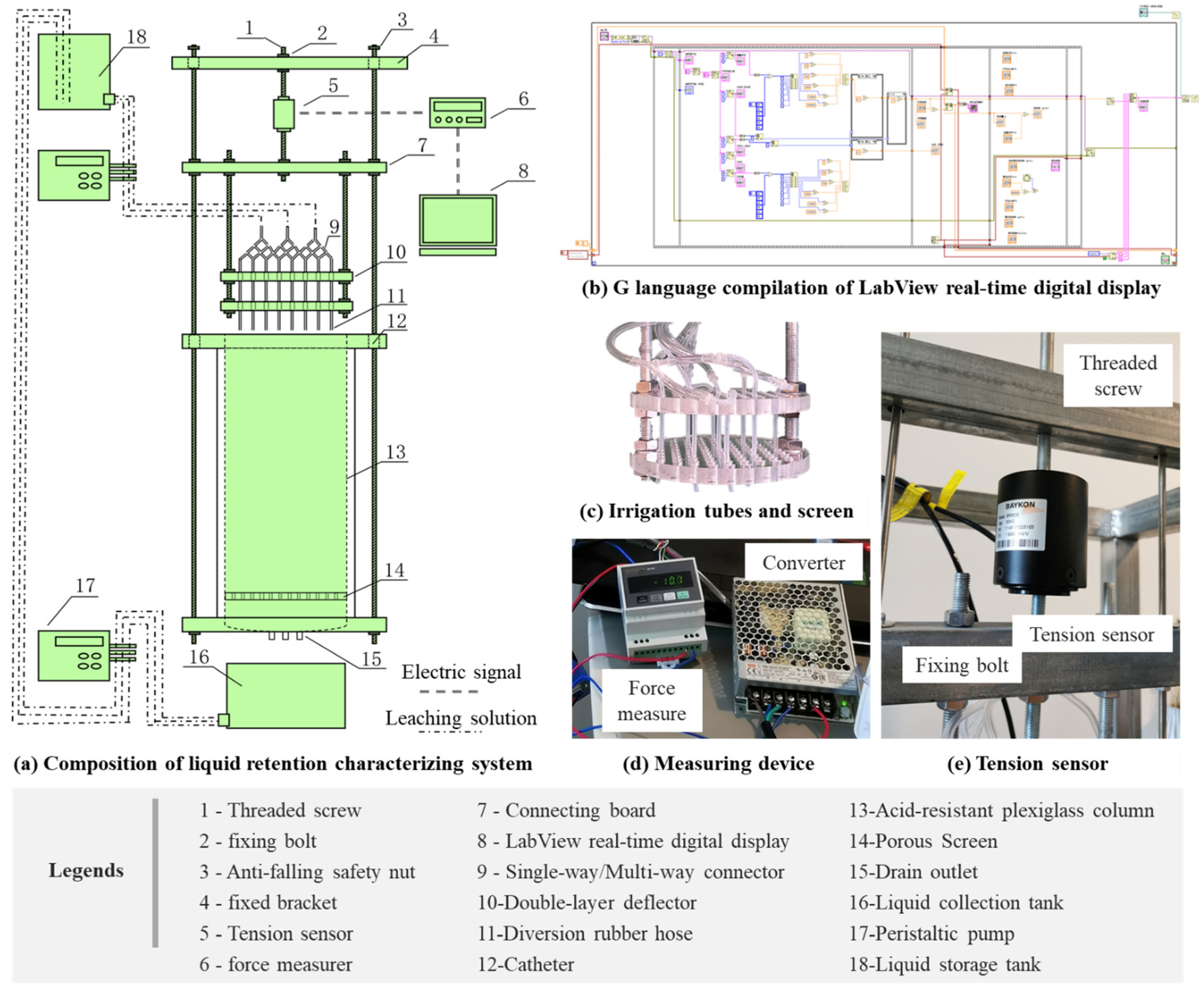
2.2. Real-Time, In-Situ Liquid Retention Characterizing System (RILRCS)
2.3. Experimental Scheme and Design
2.4. Key Parameters of Liquid Retention and Solute Transports
2.4.1. Liquid Holdup (θ) and Residual Liquid Holdup (θresidual)
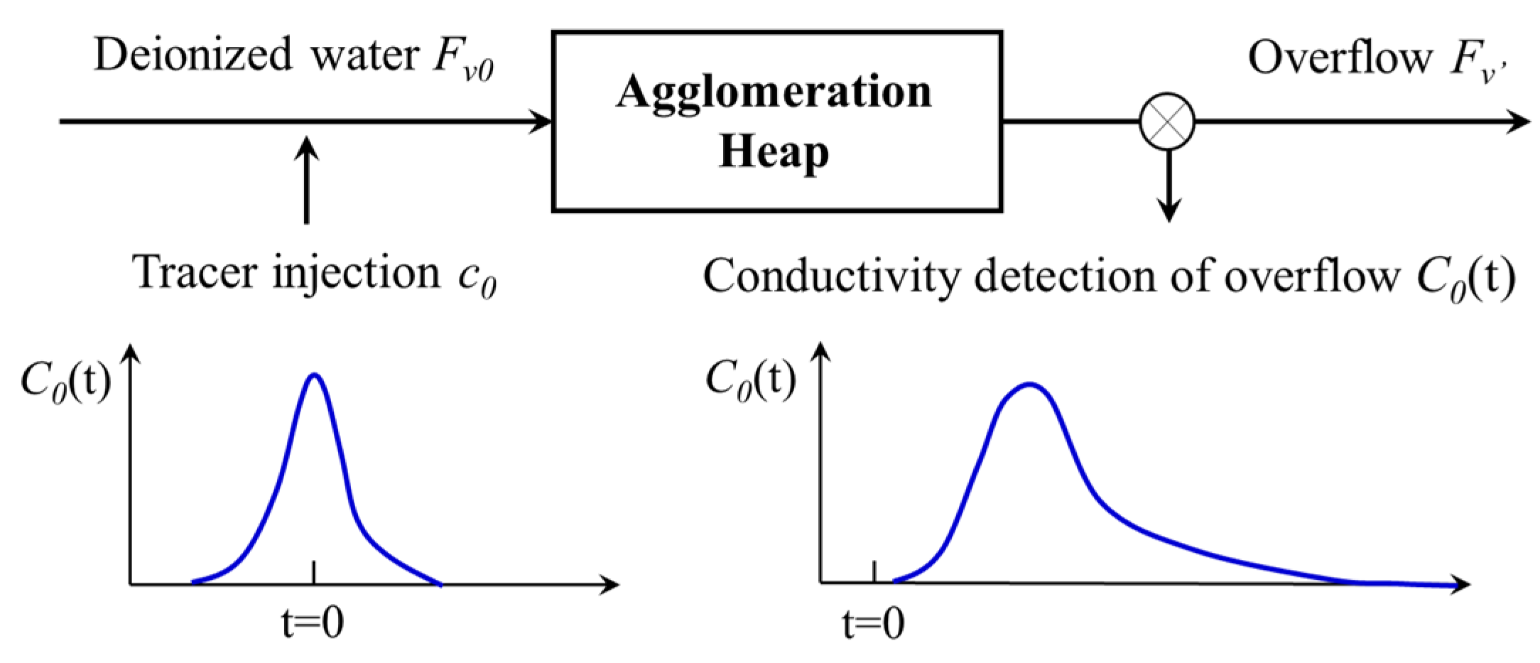
2.4.2. Solute Transport and Resident Parameters
3. Results and Discussion
3.1. Key Parameters under Geometric Mean Diameter (Rg) and Superficial Flow Rate (u)
- (1)
- Cupric ionic concentration/copper extraction rate
- (2)
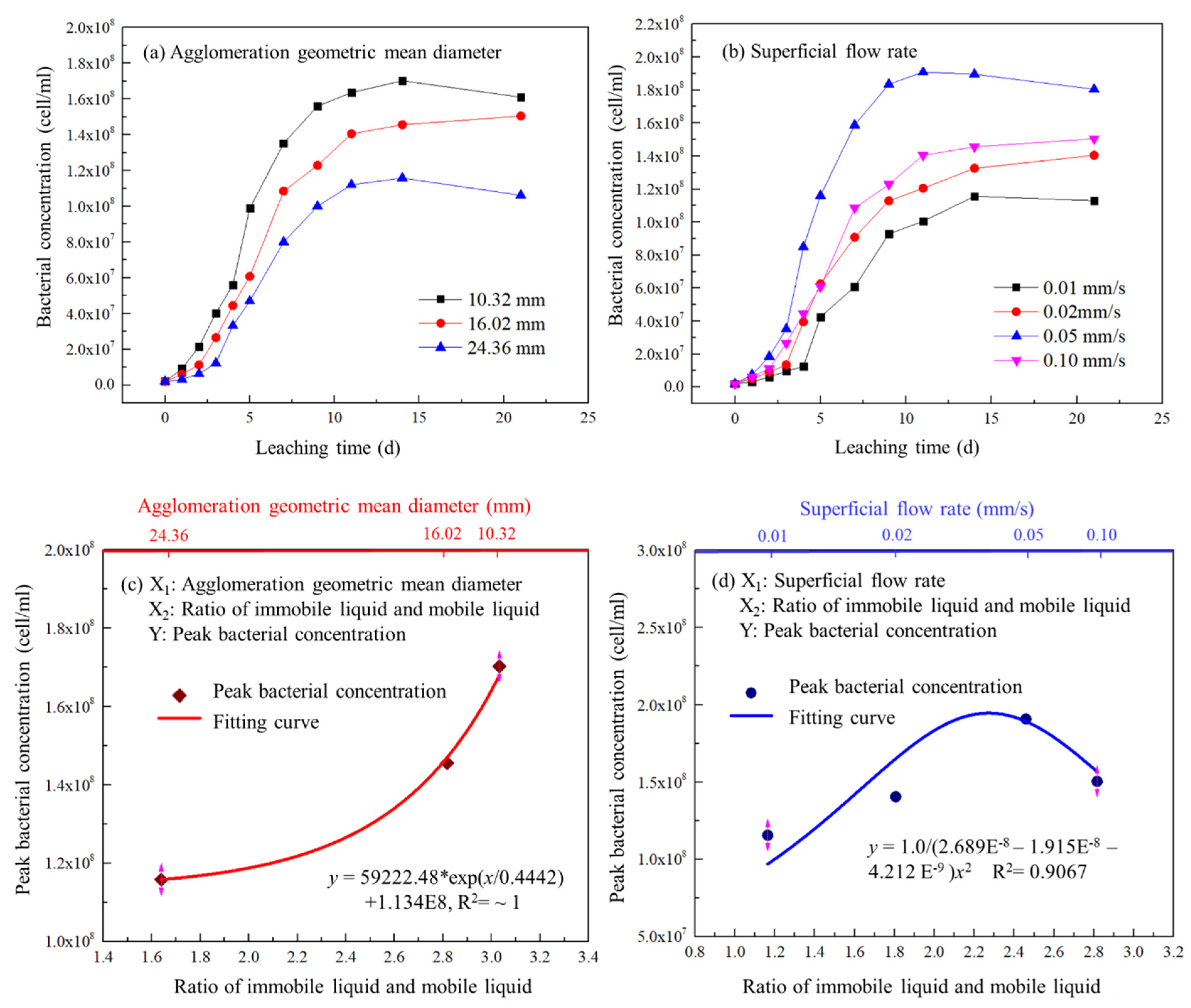
- Bacterial concentration
- (3)
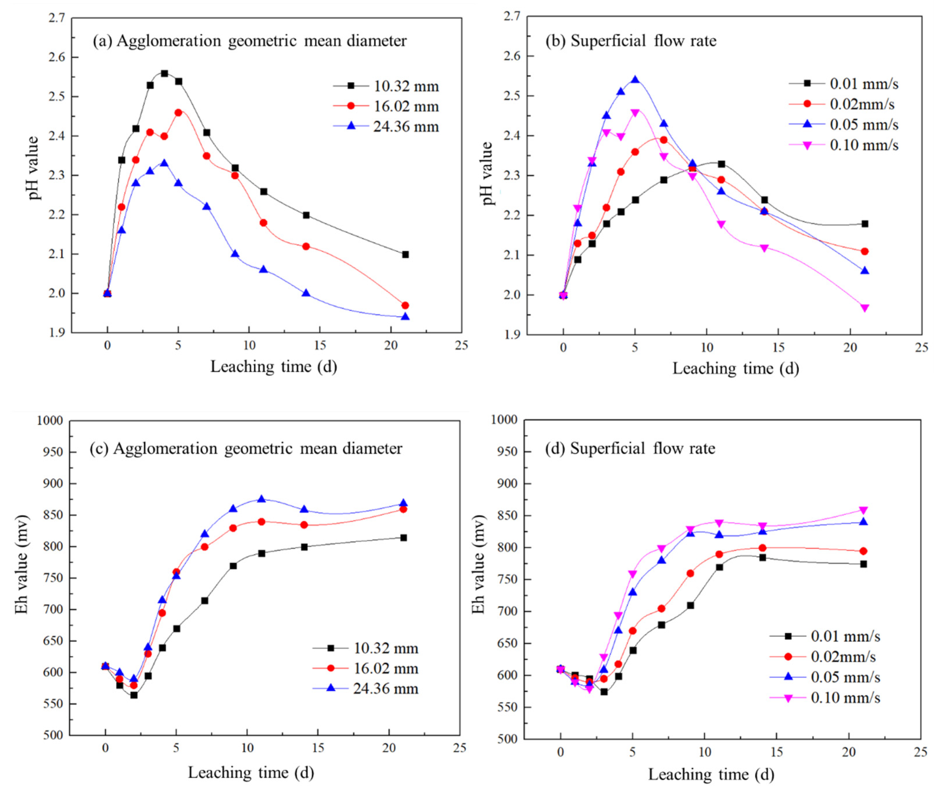
- pH/Eh value
3.2. Dynamic Liquid Retention Behavior under Different Leaching Condition
- (1)
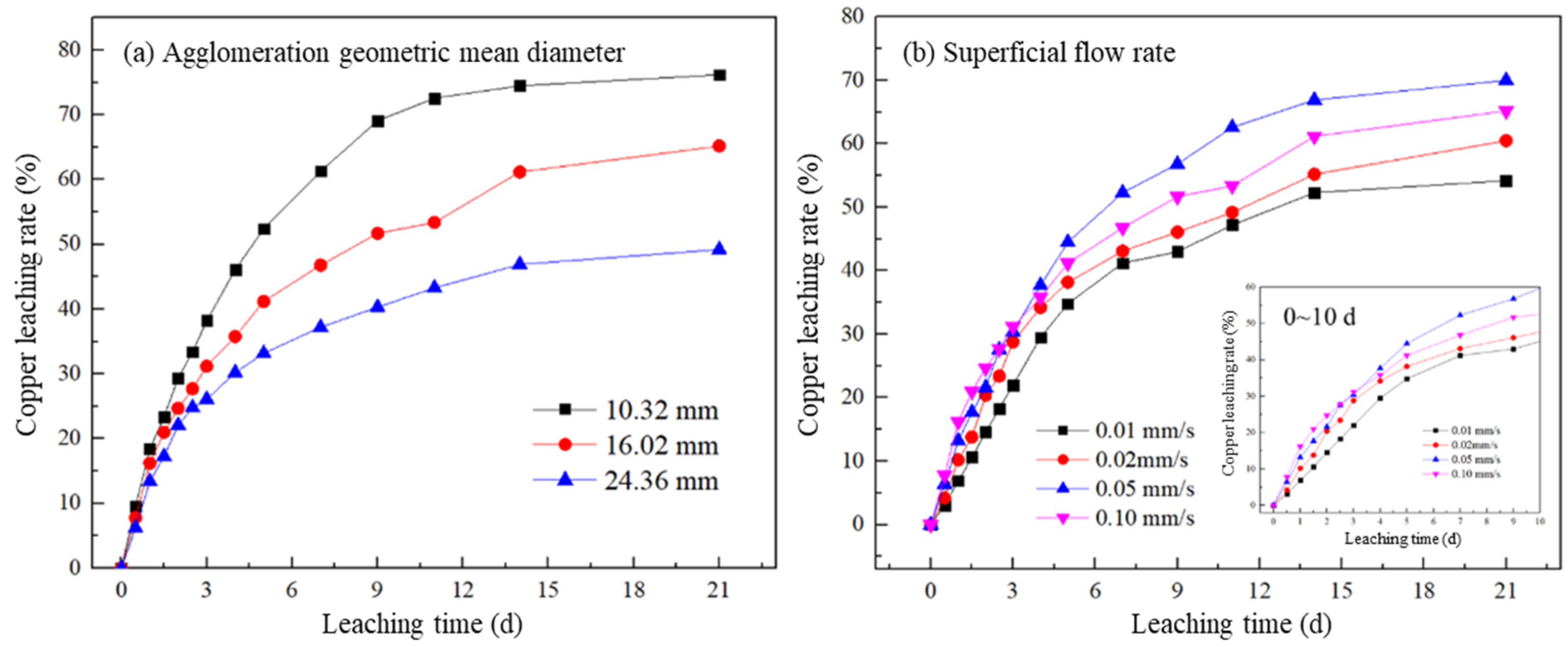
- Effect of geometric mean diameter (Rg) on dynamic liquid retention
- (2)
- Effect of superficial flow rate (u) on dynamic liquid retention
3.3. Response of Solute Transport to Dynamic Liquid Retention of Agglomerated Heaps
- (1)
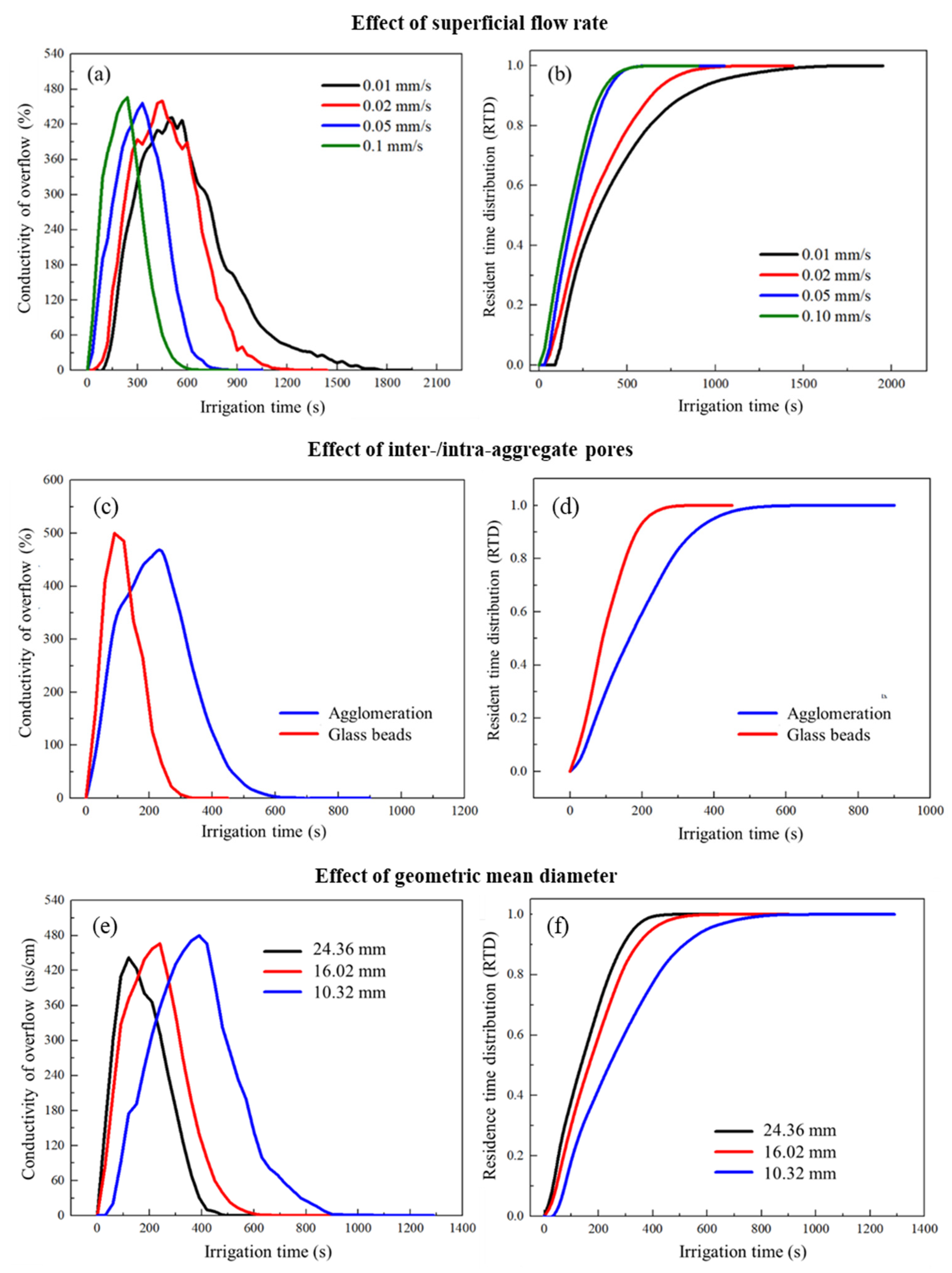
- Effect of superficial flow rate
- (2)
- Effect of inter-/intra-aggregate pores
- (3)
- Effect of geometric mean diameter
4. Conclusions
- (1)
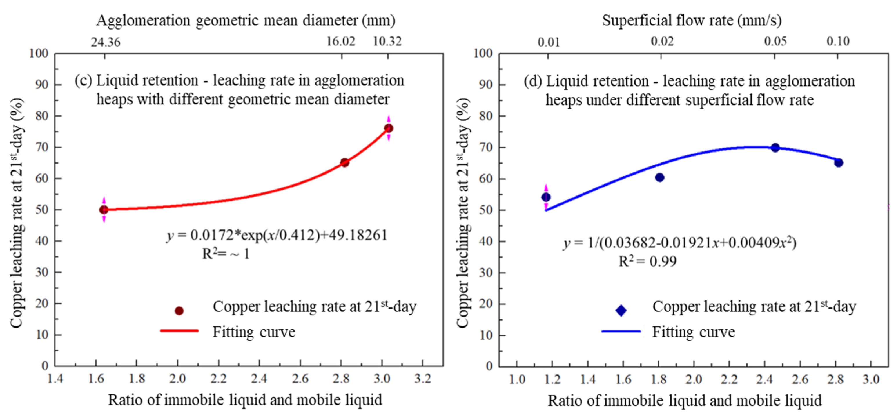
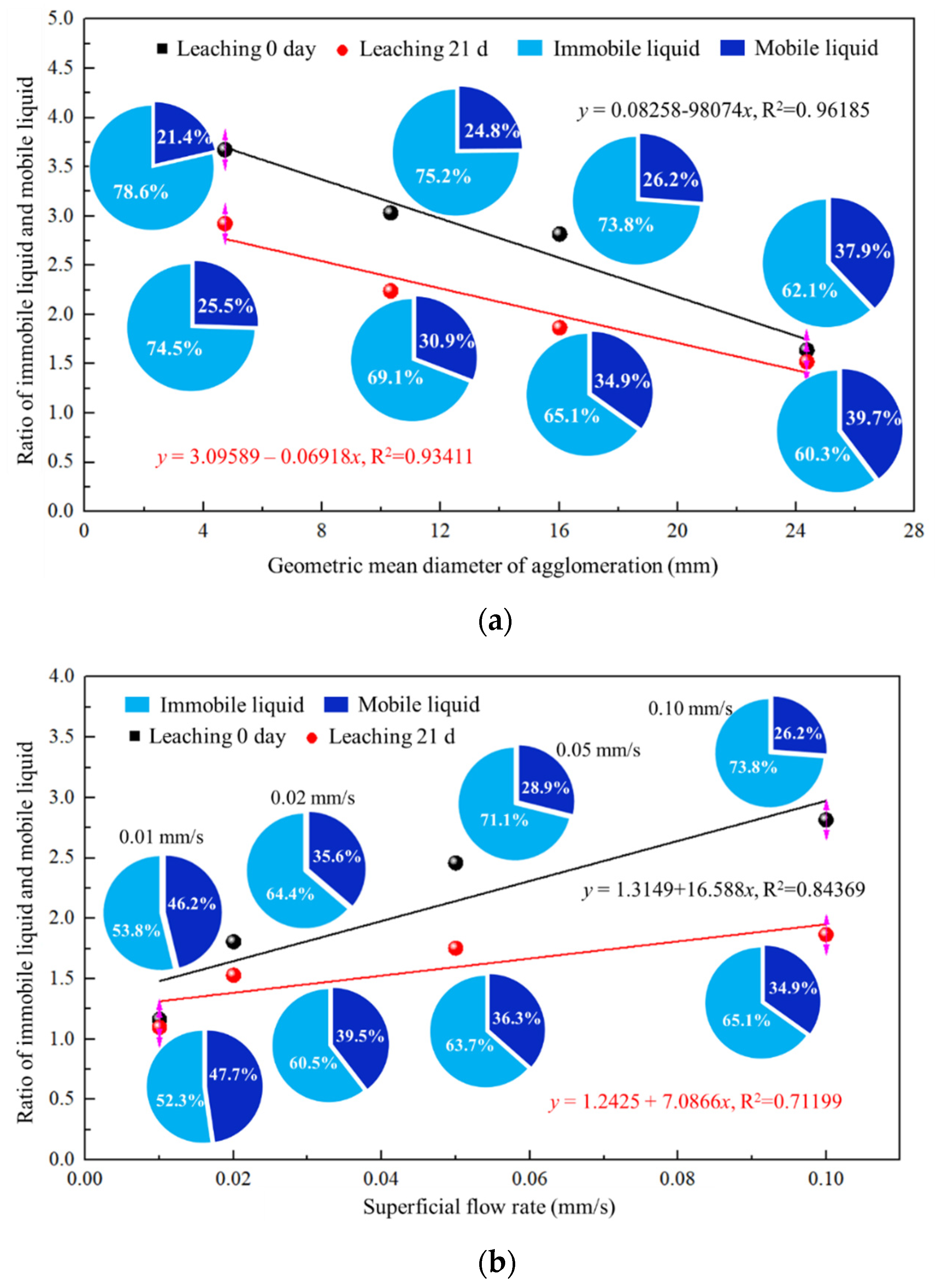
- The dynamic liquid holdup is carefully quantified via RILRCS system, the copper extraction rate is higher when the WAs diameter is smaller (10.32 mm). Increasing the surficial flow rate could decease the ratio of immobile and mobile liquid (η);
- (2)
- The RTD results show that increasing intra- porosity of agglomerated heaps and superficial flow rate could extend solute residence time. However, the excessive superficial flow rate easily results in preferential flow formation and low copper leaching rate;
- (3)
- Leaching reaction tends to promote the proportion of mobile liquid, and increase the peak liquid holdup value. The leaching reaction tends to develop the flow paths, which is mainly shown as the reduction of η.
Author Contributions
Funding
Data Availability Statement
Acknowledgments
Conflicts of Interest
References
- Yin, S.; Wang, L.; Kabwe, E.; Chen, X.; Yan, R.; An, K.; Zhang, L.; Wu, A. Copper Bioleaching in China: Review and Prospect. Minerals 2018, 8, 32. [Google Scholar] [CrossRef] [Green Version]
- Rawlings, D.E. Heavy Metal Mining Using Microbes. Annu. Rev. Microbiol. 2002, 56, 65–91. [Google Scholar] [CrossRef]
- Lizama, H.M. How Copper Dump Leaching Works. Miner. Eng. 2021, 171, 107075. [Google Scholar] [CrossRef]
- van Staden, P.J.; Petersen, J. Towards Fundamentally Based Heap Leaching Scale-Up. Miner. Eng. 2021, 168, 106915. [Google Scholar] [CrossRef]
- Yin, S.; Wang, L.; Chen, X.; Wu, A. Agglomeration and Leaching Behavior of Copper Oxides with Different Chemical Binders. Int. J. Miner. Metall. Mater. 2021, 28, 1127–1134. [Google Scholar] [CrossRef]
- van Staden, P.J.; Petersen, J. The Effects of Simulated Stacking Phenomena on the Percolation Leaching of Crushed Ore, Part 2: Stratification. Miner. Eng. 2019, 131, 216–229. [Google Scholar] [CrossRef]
- van Staden, P.J.; Petersen, J. The Effects of Simulated Stacking Phenomena on the Percolation Leaching of Crushed Ore, Part 1: Segregation. Miner. Eng. 2018, 128, 202–214. [Google Scholar] [CrossRef]
- Lewandowski, K.A.; Eisele, T.C.; Komar Kawatra, S. Agglomeration for Copper Heap Leaching. In Proceedings of the XXV International Mineral Processing Congress 2010, Brisbane, Australia, 6–10 September 2010. [Google Scholar]
- Wang, L.; Yin, S.; Wu, A.; Chen, W. Effect of Stratified Stacks on Extraction and Surface Morphology of Copper Sulfides. Hydrometallurgy 2020, 191, 105226. [Google Scholar] [CrossRef]
- Wang, L.; Yin, S.; Wu, A.; Chen, W. Synergetic Bioleaching of Copper Sulfides Using Mixed Microorganisms and Its Community Structure Succession. J. Clean. Prod. 2020, 245, 118689. [Google Scholar] [CrossRef]
- Maghsoudy, S.; Bakhtiari, O.; Maghsoudy, S. Tortuosity Prediction and Investigation of Fluid Flow Behavior Using Pore Flow Approach in Heap Leaching. Hydrometallurgy 2022, 211, 105868. [Google Scholar] [CrossRef]
- Fernando, W.A.M.; Ilankoon, I.M.S.K.; Rabbani, A.; Chong, M.N. Applicability of Pore Networks to Evaluate the Inter-Particle Flow in Heap Leaching. Hydrometallurgy 2020, 197, 105451. [Google Scholar] [CrossRef]
- Mitchell, R.J.; Mayer, A.S. A Numerical Model for Transient-Hysteretic Flow and Solute Transport in Unsaturated Porous Media. J. Contam. Hydrol. 1998, 30, 243–264. [Google Scholar] [CrossRef]
- Midoux, N.; Charpentier, J.C. Apparent Diffusity and Tortuosity in a Liquid-Filled Porous Catalyst Used for Hydrodesulfuration of Petroleum Products. Chem. Eng. Sci. 1973, 28, 2108–2111. [Google Scholar] [CrossRef]
- Shi, Z.; Zhang, Y.; Liu, M.; Hanaor, D.A.H.; Gan, Y. Dynamic Contact Angle Hysteresis in Liquid Bridges. Colloids Surf. A Physicochem. Eng. Asp. 2018, 555, 365–371. [Google Scholar] [CrossRef] [Green Version]
- Fernando, W.A.M.; Ilankoon, I.M.S.K.; Rabbani, A.; Yellishetty, M. Inter-Particle Fluid Flow Visualisation of Larger Packed Beds Pertaining to Heap Leaching Using X-ray Computed Tomography Imaging. Miner. Eng. 2020, 151, 106334. [Google Scholar] [CrossRef]
- Li, Z.; Liu, D.; Cai, Y.; Ranjith, P.G.; Yao, Y. Multi-Scale Quantitative Characterization of 3-D Pore-Fracture Networks in Bituminous and Anthracite Coals Using FIB-SEM Tomography and X-ray Μ-CT. Fuel 2017, 209, 43–53. [Google Scholar] [CrossRef]
- Wang, L.; Yin, S.; Wu, A. Visualization of Flow Behavior in Ore Segregated Packed Beds with Fine Interlayers. Int. J. Miner. Met. Mater. 2020, 27, 900–909. [Google Scholar] [CrossRef]
- Muzemder, A.S.H.; Singh, K. Intra-Pore Tortuosity and Diverging-Converging Pore Geometry Controls on Flow Enhancement Due to Liquid Boundary Slip. J. Hydrol. 2021, 598, 126475. [Google Scholar] [CrossRef]
- Or, D.; Tuller, M. Liquid Retention and Interfacial Area in Variably Saturated Porous Media: Upscaling from Single-Pore to Sample-Scale Model. Water Resour. Res. 1999, 35, 3591–3605. [Google Scholar] [CrossRef]
- Tuller, M.; Or, D. Unsaturated Hydraulic Conductivity of Structured Porous Media. Vadose Zone J. 2002, 1, 14–37. [Google Scholar] [CrossRef]
- Or, D.; Tuller, M. Flow in Unsaturated Fractured Porous Media: Hydraulic Conductivity of Rough Surfaces. Water Resour. Res. 2000, 36, 1165–1177. [Google Scholar] [CrossRef] [Green Version]
- Fagan-Endres, M.A.; Harrison, S.T.L.; Johns, M.L.; Sederman, A.J. Magnetic Resonance Imaging Characterisation of the Influence of Flowrate on Liquid Distribution in Drip Irrigated Heap Leaching. Hydrometallurgy 2015, 158, 157–164. [Google Scholar] [CrossRef]
- Ilankoon, I.M.S.K.; Neethling, S.J. The Effect of Particle Porosity on Liquid Holdup in Heap Leaching. Miner. Eng. 2013, 45, 73–80. [Google Scholar] [CrossRef] [Green Version]
- Ilankoon, I.M.S.K.; Neethling, S.J. Hysteresis in Unsaturated Flow in Packed Beds and Heaps. Miner. Eng. 2012, 35, 1–8. [Google Scholar] [CrossRef]
- Wang, L.; Yin, S.; Deng, B. Understanding the Effect of Stepwise Irrigation on Liquid Holdup and Hysteresis Behavior of Unsaturated Ore Heap. Minerals 2021, 11, 1180. [Google Scholar] [CrossRef]
- Wang, L.; Yin, S.; Wu, A. Ore Agglomeration Behavior and Its Key Controlling Factors in Heap Leaching of Low-Grade Copper Minerals. J. Clean. Prod. 2020, 279, 123705. [Google Scholar] [CrossRef]
- Wang, L.; Yin, S.; Deng, B.; Wu, A. Copper Sulfides Leaching Assisted by Acidic Seawater-Based Media: Ionic Strength and Mechanism. Miner. Eng. 2022, 175, 107286. [Google Scholar] [CrossRef]
- Ilankoon, S.K. Hydrodynamics of Unsaturated Particle Beds Pertaining to Heap Leaching. Ph.D. Thesis, Imperial College London, London, UK, 2012. [Google Scholar]
- Toye, D.; Marchot, P.; Crine, M.; Pelsser, A.M.; L’Homme, G. Local Measurements of Void Fraction and Liquid Holdup in Packed Columns Using X-ray Computed Tomography. Chem. Eng. Process. Process Intensif. 1998, 37, 511–520. [Google Scholar] [CrossRef]
- Hashemzadeh, M. Copper Leaching in Chloride Media with a View to Using Seawater for Heap Leaching of Secondary Sulfides. Ph.D. Thesis, The University of British Columbia, University Endowment Lands, BC, Canada, 2020. [Google Scholar]
- Thomas, M. Understanding Gangue Acid Consumption in Copper Sulfide Heap Leaching: Predicting the Impact of Carbonates, Silicates and Secondary Precipitates. Miner. Eng. 2021, 171, 107090. [Google Scholar] [CrossRef]
- Dreisinger, D. Copper Leaching from Primary Sulfides: Options for Biological and Chemical Extraction of Copper. Hydrometallurgy 2006, 83, 10–20. [Google Scholar] [CrossRef]
- Tshilombo, A.F. Mechanism and Kinetics of Chalcopyrite Passivation and Depassivation during Ferric and Microbial Leaching. Ph.D. Thesis, The University of British Columbia, University Endowment Lands, BC, Canada, 2004. [Google Scholar]
- Liu, R.; Hao, X.; Chen, Q.; Li, J. Research Advances of Tetrasphaera in Enhanced Biological Phosphorus Removal: A Review. Water Res. 2019, 166, 115003. [Google Scholar] [CrossRef]
- Nicol, M.J.; Zhang, S. Anodic Oxidation of Iron(II) and Copper(I) on Various Sulfide Minerals in Chloride Solutions. Hydrometallurgy 2016, 166, 167–173. [Google Scholar] [CrossRef]
- Nicol, M.J. The Electrochemistry of Chalcopyrite in Alkaline Solutions. Hydrometallurgy 2019, 187, 134–140. [Google Scholar] [CrossRef]
- Wu, A.; Yin, S.; Qin, W.; Liu, J.; Qiu, G. The Effect of Preferential Flow on Extraction and Surface Morphology of Copper Sulphides during Heap Leaching. Hydrometallurgy 2009, 95, 76–81. [Google Scholar] [CrossRef]
- Bouffard, S.C.; Dixon, D.G. Investigative Study into the Hydrodynamics of Heap Leaching Processes. Metall. Mater. Trans. B 2001, 32, 763–776. [Google Scholar] [CrossRef] [Green Version]
- Chen, K.; Yin, W.; Ma, Y.; Yang, B.; Sun, H.; Rao, F.; Liu, J. Microstructure Analysis of Low-Grade Copper Ore Agglomerates Prepared by Geopolymerization. Hydrometallurgy 2021, 200, 105564. [Google Scholar] [CrossRef]
- Yang, Y.; Yang, Y.; Gao, X.; Petersen, J.; Chen, M. Microstructure Evolution of Low-Grade Chalcopyrite Ores in Chloride Leaching—A Synchrotron-Based X-ray CT Approach Combined with a Data-Constrained Modelling (DCM). Hydrometallurgy 2019, 188, 1–13. [Google Scholar] [CrossRef]
- Von Fraunhofer, J.A. Adhesion and Cohesion. Int. J. Dent. 2012, 2012, 951324. [Google Scholar] [CrossRef] [Green Version]
- Extrand, C.W. Contact Angles and Their Hysteresis as a Measure of Liquid-Solid Adhesion. Langmuir 2004, 20, 4017–4021. [Google Scholar] [CrossRef]
- Zhang, S.; Liu, W.; Granata, G. Effects of Grain Size Gradation on the Porosity of Packed Heap Leach Beds. Hydrometallurgy 2018, 179, 238–244. [Google Scholar] [CrossRef]
- Ghorbani, Y.; Becker, M.; Mainza, A.; Franzidis, J.P.; Petersen, J. Large Particle Effects in Chemical/Biochemical Heap Leach Processes—A Review. Miner. Eng. 2011, 24, 1172–1184. [Google Scholar] [CrossRef]
- Zhang, S.; Liu, W. Application of Aerial Image Analysis for Assessing Particle Size Segregation in Dump Leaching. Hydrometallurgy 2017, 171, 99–105. [Google Scholar] [CrossRef]


| Experiment | Factors | Packed Feed Type | Geometric Mean Diameter (mm) | Superficial Flow Rate (mm/s) |
|---|---|---|---|---|
| Pulse Tracing Experiment (PTE) | Packed feed types | Solid glass beads | 16.02 | 0.10 |
| Crushed ore | 16.02 | 0.10 | ||
| Well-shaped agglomerations (WAs) | 16.02 | 0.10 | ||
| Geometric mean diameter of packed feeds | WAs | 10.32 | 0.10 | |
| WAs | 16.02 | 0.10 | ||
| WAs | 24.36 | 0.10 | ||
| Superficial flow rate (Irrigation rate) | WAs | 16.02 | 0.01 | |
| WAs | 16.02 | 0.02 | ||
| WAs | 16.02 | 0.05 | ||
| WAs | 16.02 | 0.10 | ||
| Column Leaching Experiment (CLE) | Geometric mean diameter of packed feeds | WAs | 10.32 | 0.10 |
| WAs | 16.02 | 0.10 | ||
| WAs | 24.36 | 0.10 | ||
| Superficial flow rate (Irrigation rate) | WAs | 16.02 | 0.01 | |
| WAs | 16.02 | 0.02 | ||
| WAs | 16.02 | 0.05 | ||
| WAs | 16.02 | 0.10 |
Publisher’s Note: MDPI stays neutral with regard to jurisdictional claims in published maps and institutional affiliations. |
© 2022 by the authors. Licensee MDPI, Basel, Switzerland. This article is an open access article distributed under the terms and conditions of the Creative Commons Attribution (CC BY) license (https://creativecommons.org/licenses/by/4.0/).
Share and Cite
Wang, L.; Yin, S.; Zhang, X.; Yan, Z.; Liao, W. Hydrodynamic Hysteresis and Solute Transport in Agglomerated Heaps under Irrigation, Stacking, and Bioleaching Controlling. Minerals 2022, 12, 1623. https://doi.org/10.3390/min12121623
Wang L, Yin S, Zhang X, Yan Z, Liao W. Hydrodynamic Hysteresis and Solute Transport in Agglomerated Heaps under Irrigation, Stacking, and Bioleaching Controlling. Minerals. 2022; 12(12):1623. https://doi.org/10.3390/min12121623
Chicago/Turabian StyleWang, Leiming, Shenghua Yin, Xuelan Zhang, Zepeng Yan, and Wensheng Liao. 2022. "Hydrodynamic Hysteresis and Solute Transport in Agglomerated Heaps under Irrigation, Stacking, and Bioleaching Controlling" Minerals 12, no. 12: 1623. https://doi.org/10.3390/min12121623