1. Introduction
In the mineral processing of sulphide ores, flotation technology is widely used to separate and concentrate targeted valuable minerals. During this action, a residual solid, called tailings, is produced and rejected into tailing ponds [
1,
2]. This material is a mixture of fine particle-sized gangue minerals and process water. Depending on the characteristics of the ore and flotation process, tailings may contain reactive sulphides which increase the risk of acid rock drainage (ARD) in disposal sites [
3,
4]. In addition, sulphide minerals in tailings may host valuable metals that are currently lost [
3]. If feasible, an additional flotation step may be applied to separate remaining sulphides (typically pyrite FeS
2 and/or pyrrhotite Fe
0.83–1S) from non-sulphidic gangue material, to produce “high-sulphur (HS) tailings” or “sulphur concentrate”. This enables better management of the ARD risk and later recovery of valuable metals from historic ponds.
Some HS tailings and related side-streams have contained such a high concentration of valuable metals that their additional treatment has been economically possible. For example, Kasese Cobalt Company (KCC) in Uganda treated HS tailings for Co recovery by utilising tank bioleaching technology [
5]. Similarly, Mondo Minerals in Finland utilised tank bioleaching of sulphur concentrate for Ni recovery [
6]. Even though these plants utilised a similar leaching technology, their behaviour was different: the KCC leaching circuit required CaCO
3 to neutralise the excess acidity during the leaching, while the Mondo Minerals plant faced a net acid consumption and thus external H
2SO
4 addition was required. The explanation for this difference is likely the different mineralogy, as the KCC material was extremely rich in pyrite, while the Mondo Minerals feed contained pyrrhotite and pentlandite [
5,
6].
Pyrrhotite is a highly reactive mineral that consumes plenty of acid and oxidant in leaching circuits, as shown in Equations (1)–(3) [
7,
8,
9,
10].
Generally, a tank bioleaching process maintaining highly oxidative conditions is critical to enabling the dissolution of targeted minerals [
5,
6,
10,
11]. The main dissolution reactions are considered to take place between Fe
2(SO
4)
3 and sulphide minerals, followed by re-oxidation of the produced FeSO
4 by O
2 and acid, as shown in Equation (4) [
12].
According to the above-mentioned Equations (1)–(4), high pyrrhotite content may cause several challenges in a tank bioleaching process. As pyrrhotite is highly reactive [
8], it may deplete the system of oxidants and maintain non-oxidative conditions. This may take place due to the presence of pyrrhotite itself or due to its dissolution product H
2S that also consumes Fe
2(SO
4)
3 and O
2 [
12]. Theoretically, this should result in halted leaching of targeted valuable minerals that require strongly oxidative conditions for their dissolution. Moreover, the non-oxidative conditions may lead to elevated acid consumption as pyrrhotite leaching proceeds via acid in these conditions [
7]. Even though bioleaching microorganisms can produce H
2SO
4 from oxidising S
0, the realised net acid balance is easily negative when plenty of pyrrhotite is present. High acid consumption along with increased aeration may need to take place, especially in the first reactor of the bioleaching series, due to the high pyrrhotite reactivity and Fe oxidation–reduction cycle. Moreover, additional costs may be generated due to supplementing carbon for microorganisms as CO
2 since CaCO
3 cannot be utilised in acid-consuming processes.
The most common methods to separate pyrrhotite from ores are magnetic separation and flotation [
1,
2]. However, as these methods are not always viable, non-oxidative acid leaching has been considered to offer an alternative technique for removing pyrrhotite [
13]. Similarly, as with magnetic separation and flotation, the non-oxidative acid leaching would result in benefits when applying the conventional pyrometallurgical recovery route, as decreased pyrrhotite content decreases slag and SO
2 production volume and transportation costs [
14]. However, according to Equation (1), the non-oxidative acid leaching may also enable the recovery and valorisation of pyrrhotite-related Fe and S as FeSO
4 and H
2S, respectively [
15]. Finally, the non-oxidative acid leaching may result in improved leaching kinetics and smaller chemical consumption in any later oxidative (bio)leaching of valuable metals, as explained earlier.
The non-oxidative acid leaching of pyrrhotite has been reported to start with an induction period, resulting in only minor H
2S and soluble Fe production. The induction period is followed by a rapid leaching phase with major H
2S and soluble Fe release. Finally, the dissolution is slowed down by passivation due to produced sulphur layers, which must be dissolved before continuing efficient pyrrhotite leaching [
16]. The temperature and acidity have been observed to play a major role in leaching efficiency. According to the experiments conducted with HCl, at lower temperatures the non-oxidative leaching of pyrrhotite is slow and requires high acid concentration, while in higher temperatures the reaction is more active and proceeds to complete pyrrhotite dissolution with less acid [
16,
17]. When applying H
2SO
4 in non-oxidative leaching, an activation (e.g., with hydrogen) may be required to decrease the Fe:S molar ratio of pyrrhotite closer to 1 to increase the dissolution efficiency [
15]. Moreover, when using H
2SO
4, saturation may result in the formation of FeSO
4 precipitates. The increased H
2SO
4 concentration has been shown to decrease FeSO
4 solubility, while the temperature orders the number of hydrates of the crystal and influences the solubility [
18].
In this study, an HS tailings sample, consisting of approximately 53 wt% pyrite and 24 wt% pyrrhotite, was subjected to non-oxidative H2SO4 leaching. The general objective was to utilise non-oxidative leaching as a pre-treatment before oxidative tank bioleaching for valuable metals (Co, Ni, Zn and Cu) recovery. The related tank bioleaching research will be reported later in an upcoming publication. The novelty of this research, compared to the existing literature, was to clarify the suitable operative process parameters of the non-oxidative leaching process. Therefore, a continuous mode validation test was conducted for the HS tailings sample to determine the H2SO4 consumption and retention time of the process. In addition, the possibilities of utilising the produced H2S gas and FeSO4 leachate was examined.
2. Materials and Methods
2.1. Sample Material, Milling and Analytics
The HS tailings sample was obtained from an active mill, where the milled input ore is treated via flotation to produce a Cu concentrate, a Zn concentrate and finally an HS tailings fraction that is stored in a pond. Two HS tailings sample barrels (namely HST-1 and HST-2) were obtained for the studies. Both HST-1 and HST-2 were first dried at room temperature and then homogenised by mixing. The additional milling of samples was conducted using a Mergan ball mill with stainless steel balls with full 5 kg loadings of the HS tailings for 200 min. The mill space and used water were purged with N2 gas to prevent oxidation of sulphides during milling. Milling resulted in a d80 < 20 µm particle size according to a laser diffraction measurement (Beckman Coulter, Brea, CA, USA). The modal mineralogy of the sample was determined (MLA 600, built on Quanta 600 SEM by FEI Company and equipped with MLA software version 3.1.4.686, Thermo Fisher Scientific Inc., Waltham, MA, USA). The above-mentioned works were subcontracted from the Geological Survey of Finland (GTK). Milled HS tailings samples were packed under vacuum into bags and shipped to the VTT Technical Research Centre of Finland for leaching studies. The elemental composition was determined using ICP-OES (ICP-OES; 5100 SVDV, Agilent Technologies, Santa Clara, CA, USA) by complete digestion with microwave-assisted acid digestion (UltraWAVE, Milestone, Sorisole, Italy). In the actual leaching studies, pH and RedOx potential were measured using a Consort C3040 multiparameter analyser and Van London-pHoenix Co. pH and RedOx electrodes (Ag/AgCl in 3 M KCl; pH electrode calibration 1.68/4.01/7.00; RedOx electrode calibration +650 mV). Solution samples of leaching studies were analysed using ICP-OES (ICP-OES; 5100 SVDV, Agilent Technologies, Santa Clara, CA, USA).
2.2. Screening Tests
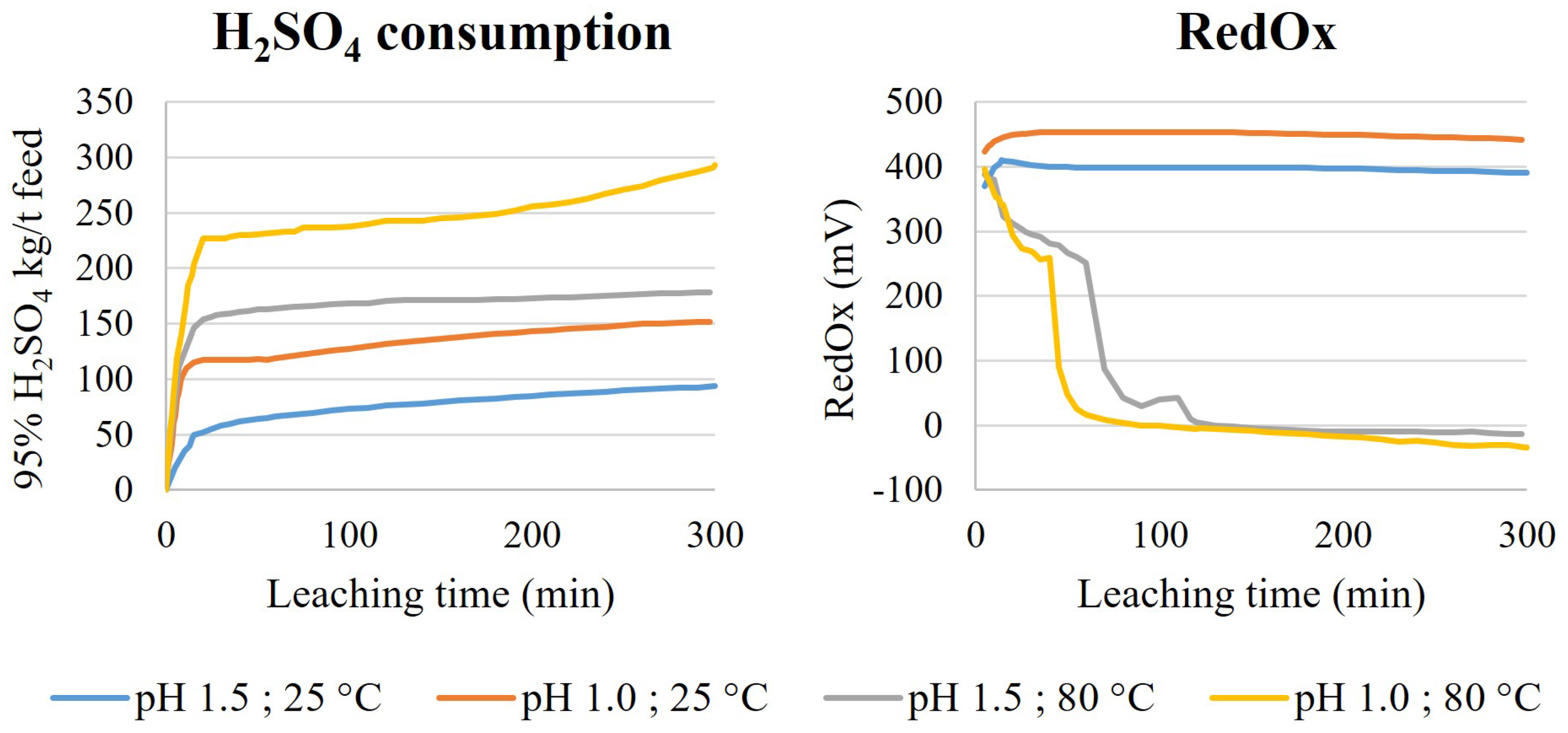
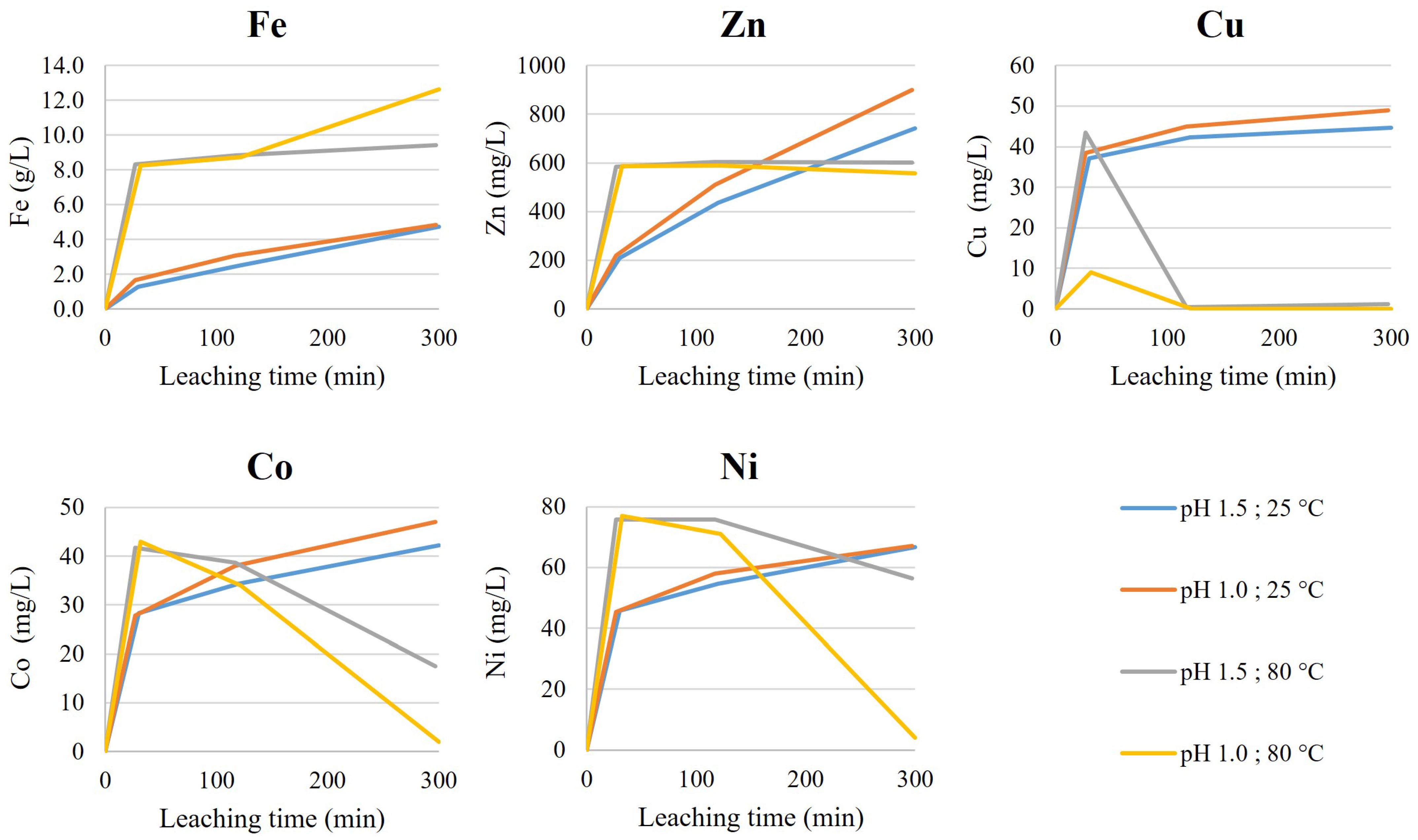
Screening tests of the non-oxidative leaching were conducted using a HST-1 sample. The leaching setup consisted of 1 L borosilicate glass reactor, equipped with a lid, baffles, an overhead stirrer and a blade impeller (1180 rpm). The temperature was controlled automatically with a heat plate and temperature sensor. The pH was controlled with an automatic titrator, using 4 M H2SO4 as a titrant. Released gases and fumes were collected from the reactor freeboard with a reflux condenser and transferred to two scrubbers (500 mL round-bottomed, two-neck borosilicate flasks) connected in series and both containing 350 mL of NaOH (400 g/L). The vacuum for gas collection was created with a water jet pump. As the reactors were not airtight, replacement air flowed into the reactor freeboard from the agitator shaft hole.
The non-oxidative leaching was conducted with 1 L working volume by first mixing distilled water and a dry HS tailings sample (200 g/L), heating the slurry and then starting the acid titration. The desired pH (1.5 or 1.0) and temperature (25 °C or 80 °C) were then maintained for 300 min. During the operation, the acid consumption, pH, RedOx and temperature were monitored. Scrubber performance was monitored in the fume hood with an H2S gas detector. Slurry samples (10 mL) were taken after 30, 120 and 300 min for leachate analysis and solids were returned to the reactor after 10 min of settling. After the tests, slurries were vacuum filtrated using a Buchner (filter pore size 0.45 µm) and the filtrate volume was measured. The leach residue was washed with distilled water (300 mL) in the Buchner. The leach residue was then removed from the filter and dried at 60 °C.
2.3. Validation Tests
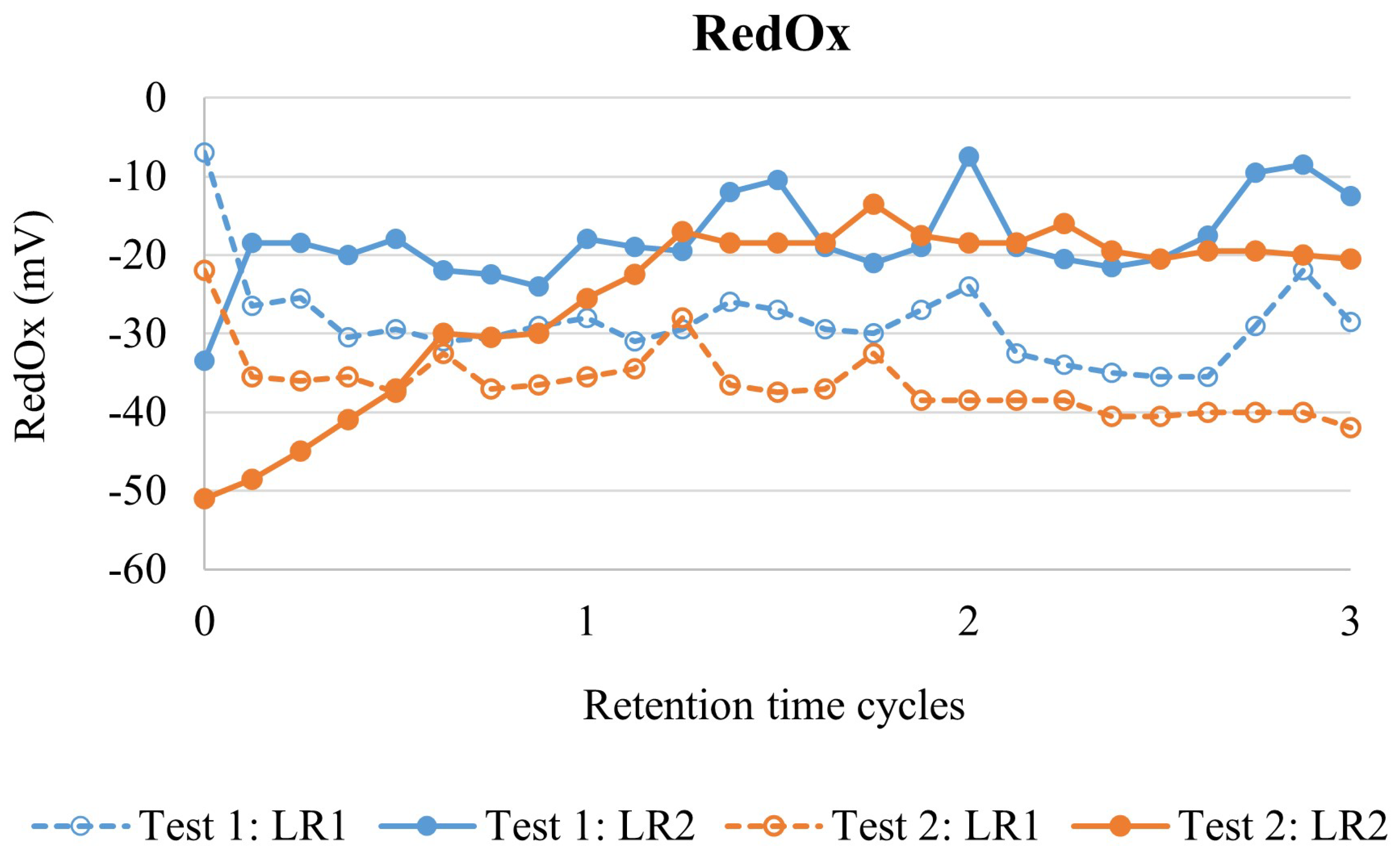
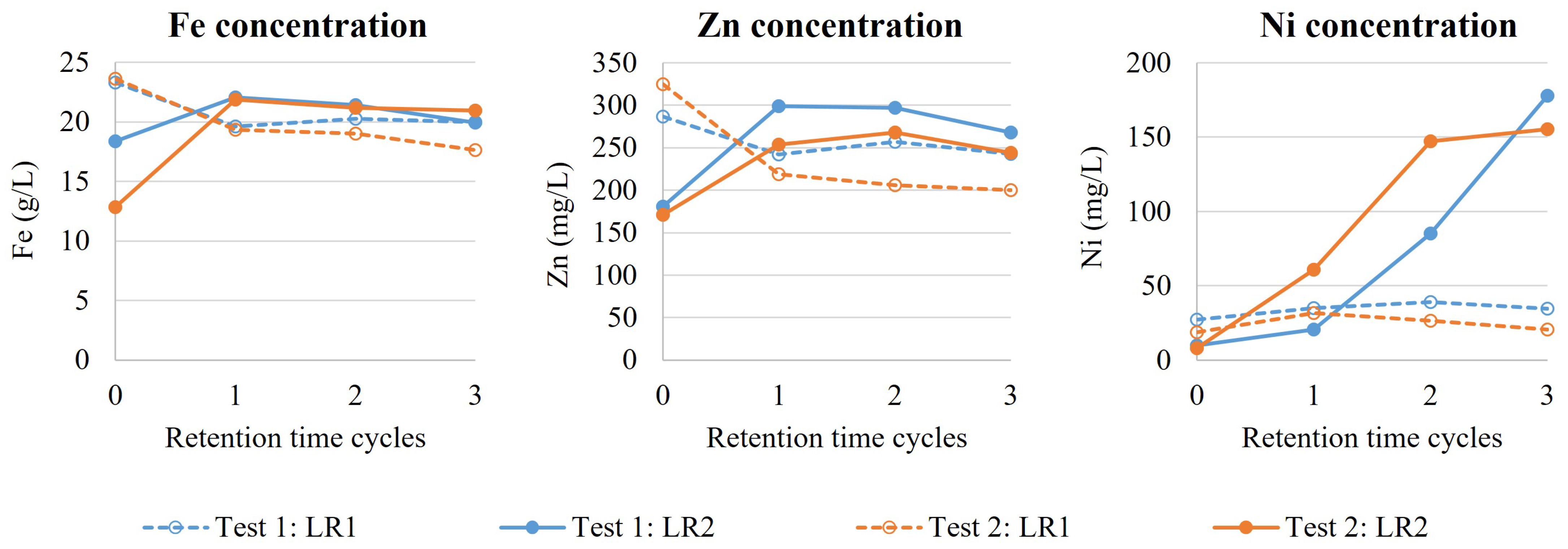
The dry HS tailings sample (HST-2) was pulped with distilled water (200 g/L) at room temperature in a 10 L feed tank, equipped with a lid, baffles, an overhead stirrer and a blade impeller (800 rpm). The feed tank was refilled with 6 L of slurry every 90 min during continuous mode validation. The slurry was continuously pumped from the feed tank into the leaching circuit with a constant flowrate. The pH, RedOx, temperature, solid content, slurry volume and outflow of the feed tank were continually monitored.
The leaching circuit consisted of two 5 L stirred-tank reactors, equipped with lids, baffles, output nozzles, overhead stirrers and blade impellers (800 rpm). The temperature was controlled automatically with heat plates and temperature sensors. Reactors were connected in series as a cascade setup; the slurry was transported from the first leaching reactor (LR1) into the second leaching reactor (LR2), and from LR2 to the vacuum filtration Buchner using gravitational force via output nozzles. The leaching circuit was equipped with pumps to supplement 5.5 M H2SO4 primarily to LR1 and, if necessary, also to LR2. The molarity of acid solution was selected to compensate the evaporation. Both LR1 and LR2 were equipped with reflux condensers and formed gases were transferred to the scrubbing system. The scrubbing system consisted of two Duran GLS80 reaction vessels connected in series, both filled with 1 L NaOH (400 g/L), and suction was generated using a vacuum pump. As reactors were not airtight, replacement air flowed into the reactor airspace from the agitator shaft hole.
The leaching system was ramped up by filling LR1 and LR2 with slurry (200 g/L) and heating both reactors to 90 °C. Then, both reactors were supplemented with H2SO4 to reach and maintain pH 1.0 in batch mode for 60 min (half of the total retention time). After the ramp-up phase, the slurry feed pump was started (5.0 L/h) resulting in a continuous mode with a target hydraulic retention time (HRT) of 120 min. The continuous mode validation test was operated for 3 HRT cycles, which is generally considered to result in steady-state conditions if no changes are made to operational parameters. The target pH of the leach circuit was pH 1.0, measured from the LR2. The acid was provided with continuous and stable pumping (0.65 L/h) solely to LR1. The pH, Redox, temperature and acid flow were continually monitored during the operation. The solids content of LR1 and LR2 was determined on every half HRT cycle (60 min), while solution and solid analysis were conducted on every HRT cycle (120 min). LR2 output slurry flowrate was monitored to spot any anomalies during the operation. During the continuous mode validation test, filtration was conducted continuously for the LR2 output slurry. After removing the filtrate, leach residue was washed in the Buchner filter with distilled water (3000 mL), dried at room temperature, homogenised by mixing and analysed for mineralogical composition.
The validation test was performed in duplicate.


