Article

Mud Crab’s Mottled, Deep-Blue Exoskeleton: Surface Morphology and Internal Microstructure

1
National Institute for Materials Science, 1-2-1, Sengen, Tsukuba 305-0047, Japan
2
Japan Testing Laboratories, 1-56 Uchihara, Ohgaki, Gifu 503-0936, Japan
*
Author to whom correspondence should be addressed.
Minerals 2022, 12(12), 1607; https://doi.org/10.3390/min12121607
Submission received: 1 November 2022 / Revised: 12 December 2022 / Accepted: 12 December 2022 / Published: 14 December 2022
(This article belongs to the Special Issue Feature Papers in Biomineralization and Biominerals)

Abstract

:
The claws of the mud crab, Scylla serrata, are huge in comparison with its body size. Many bulges ranging from 5 to 23 μm in height and 90 to 146 µm in diameter were observed on the mottled, deep-blue exoskeleton surface of the mud crab’s claw. These cuticle bulges were closely related to irregularly present exocuticles on the surface layer of the exoskeleton’s cross section. The bulges exist between the exocuticles, and at the apex of these bulges was a tube that bundled many pore canals that penetrated the exoskeleton. This tube was thick (62–66 µm) near the inner side and narrowed (12–22 µm) toward the outer surface. On the other hand, the exocuticles had a heterogeneous tissue structure in a coarse region extending normally to the surface, with a diameter of 3 to 7 µm, and a dense region between them. Calcium concentrations were high in the dense region, and phosphorus and magnesium concentrations were high in the coarse region. As a result, the mechanical properties (hardness: H and modulus: Er) were distributed inside the exocuticle, and the mapping of H and Er using a nanoindentation test clarified the heterogeneity.

1. Introduction

The rapid progress of additive manufacturing has made it possible to create materials with hierarchical and complicated tissue structures [1,2,3,4,5]. Therefore, the complex microstructure and hierarchical structure of organisms are being elucidated with the aim of improving the functions and properties of materials [5,6,7,8]. Among them, the exoskeleton of decapod crustaceans, which has the highest force-per-unit weight in organisms [9,10,11], is characterized by a microstructure with a twisted plywood–pattern structure (TPS) rotated 180° around an axis normal to the surface [10,12,13]. It is formed by a certain stacking of the bundles of chitin fiber wrapped by protein, and the exoskeleton has excellent mechanical properties [14,15,16,17].
Usually, a crustacean’s exoskeleton is composed of four layers: the epicuticle (thinnest wax layer of the outermost surface), the exocuticle (hardest layer), the endocuticle (thickest layer), and the membranous (adjacent to cells) layer [18,19]. The exoskeleton is formed by the transport of nutrients and ions from the cells through the thick pore-canal tube (pct) that penetrates the exoskeleton surface and the thin pcts perpendicular to it. The exocuticle (exoC) and endocuticle (endoC) are mineralized layers that play a major role in achieving the excellent mechanical properties of the exoskeleton; these two layers have habitat-adapted tissue structures.
The exoC and endoC of the American lobster, Homarus americanus, and the brown crab, Cancer pagurus, that inhabit shallow seawater have a TPS with a stacking height (Sh) [14,20,21]. The Sh of the hard exoC is usually smaller than that of the soft endoC. While the exoC of the coconut crab, Birgus latro, a terrestrial crustacean, has a very fine Sh, the endoC is characterized by a porous structure in which many pores are regularly arranged perpendicular to the exoskeleton surface [10,15,22,23]. The swimming crab, Portunidae, which inhabits the sandy bottom of relatively shallow inner bays, has a variety of colors, and many points about the exoskeleton are unclear. Based on multi-laser micro-Raman spectroscopy, Nakvapil et al. reported that the morphology of white, blue, and red cuticles in the claws of the Atlantic blue crab, Callinectes sapidus, had systematic differences at the ultrastructure level [24]. Differences in chemical components and the diameter and spacing of pore canals inside the exoskeleton due to the color of the exoskeleton surface were examined in detail, but tissue structures with and without a TPS and mechanical properties were not discussed. The shell color of the mud crab, Scylla serrata, whose claws are huge in comparison with its body size in the family Portunidae (Crustacea: Decapoda), was a mottled deep blue, but the top of the claw was white [25,26,27], as shown in Figure 1a. This discoloration point (DP) observed on the claw surface proceeded to the inside of the exoskeleton and was visible as a discoloration line (DL) near the center of the thickness of the claw exoskeleton (Figure 1b). In the exoskeleton of the white surface, although the microstructure was characterized by a TPS throughout the entire thickness, the proportion of the pores, composition, and hardness varied gradually, with the DL as the boundary [27]. The striped pattern on the polished surface originated from the TPS, and its spacing indicated the Sh. On the other hand, in the exoskeleton of the mottled, deep-blue surface, the irregularly arranged exoC on the surface and the endoC with a TPS were observed (Figure 1c,d). The exoC thickness was 1.5–3.0% of the exoskeleton thickness, and this was close to the percentage of the exoC of the blue crab [24]. The presence of the irregularly arranged exoC was also observed in the brown crab [20]. However, these studies did not examine why the exoC is irregularly present nor their microstructures and mechanical properties in detail.
The exoC in the mottled, deep-blue area (hereafter designated as the blue area) of the mud crab, unlike the TPS, had a fish scale-like tissue extending normally to the surface [27], as shown in Figure 1c. Since such tissue was not visible in the white area, it may be related to the cuticle color or its surface condition. Additionally, this tissue is expected to have considerable heterogeneity in microstructure and mechanical properties and is likely to differ from the relatively homogeneous and hard exocuticle layer, with a TPS reported in many papers [10,12,13,14,15,20,21]. We focused on the surface of the blue area of the mud crab’s claw and the fish-scale-like tissue of the exoC existing irregularly on its surface layer.

2. Materials and Methods

2.1. Specimen Preparation

A large, male mud crab (body weight 1265 g, carapace width 167.3 mm, carapace length 113.4 mm) in the intermolt stage was obtained live from a local market in Naha, Okinawa, Japan [27]. For comparison, two other mud crabs (body weight 1578 g and 2138 g) were obtained from the same market. Samples were stored frozen at −18 °C to prevent natural decay processes and transported to NIMS in Tsukuba for analysis. The large right claw (length 141.8 mm, width 66.5 mm, thickness 39.5 mm) was removed, and a handsaw was used to cut samples from the blue area of the fixed finger. The samples were then thawed under running water for 300 s and prepared both parallel and vertical to the exoskeleton surface to expose a cross section. After drying for 48 h or more, the mounting cup in which the sample was set was filled with epoxy (EpoFix Resin, Struers, Tokyo, Japan) at room temperature, left to cure at room temperature for approximately 12 h, and then polished. Details of the procedures and microstructures for this sample were given earlier [15,27].

2.2. Laser Scanning Microscope Observation

Laser microscopes were used to identify tissue differences on the cross section with greater accuracy and to observe the exoskeleton surface unevenness. A 3D laser scanning microscope (VK-X200/210, Keyence Corporation, Osaka, Japan) that can perform profile, roughness, and thickness measurements with 0.5 nm z-resolution was employed. The samples for the surface observation were placed in air for more than 48 h after thawing, and then the surface changes over time were observed. A fractured sample was prepared to investigate the relationship between the outer surface and the cross-sectional structure. These test pieces were cut from the movable finger with a handsaw, and the outer surface and fracture surface of the samples were observed at the same time.

2.3. SEM Observation and EDS Analysis

Before the scanning electron microscope (SEM) observation, the sample was coated with about 2 nm of osmium (Neo Osmium Coater, Meiwafosis Co., Ltd., Tokyo, Japan) to characterize the microstructure and chemical compositions. A focused ion beam (FIB)–SEM dual-beam instrument (Scios 2, Thermo Fisher Scientific, Waltham, MA, USA) at an accelerating voltage of 2kV and a secondary electron detector in a chamber, or an in-lens annular back-scattered electron detector, was used for microstructure characterization. An energy-dispersive X-ray spectroscope (EDS) attached to the FIB–SEM was used for the compositional analysis. A large silicon-drift detector (Ultim Max 170, Oxford Instruments, Abingdon, Oxfordshire, GB) ensured high-efficiency detection and low statistical error in quantitative analysis. The EDS analysis was conducted at an accelerating voltage of 15 kV.

2.4. Fracture-Surface Observation by SEM

A fracture surface was observed to examine the pct//x and the tissue structure of the exoC in the blue area. A handsaw was used to cut a test sample from the movable finger for observation of the fracture surface, and then the piece was placed in air for more than 48 h. The sample was broken by hitting the back of a chisel with a hammer before SEM observation. Then the fracture surface was treated with an osmium coating. The fracture surface was observed via SEM (JEOL JSM-7900F, Tokyo, Japan) at an accelerating voltage of 2 kV and with an Everhart–Thornley secondary electron detector.

2.5. Nanoindentation Tests

To measure the local mechanical properties of the exoC, nanoindentation testing was performed at an ambient temperature using an ENT-NEXUS (ELIONIX, Tokyo, Japan) with a Berkovich diamond indenter at an angle of 115°. Tests were conducted for the exoC in the blue area. First, for two regions in the exoC with fish-scale–like tissue, the loading curve consisted of a 5 s loading time, holding for 5 s at the maximum force (Fmax) of 5 mN, and then a 5 s unloading time. That is, the indentation speed (V) was 1 mN/s. Next, to create a map of the mechanical properties of the exoC, additional tests were performed at intervals of 2 μm with the same V (Fmax = 0.5 mN and a 0.5 s loading time). The hardness (H) and reduced elastic modulus (Er) were analyzed from the unloading curve by using the Oliver–Pharr method employed in biological studies [10,14,22,28]. The contour maps of H and Er were created using SigmaPlot 14.5 (HULINKS Inc., Tokyo, Japan).

3. Results and Discussion

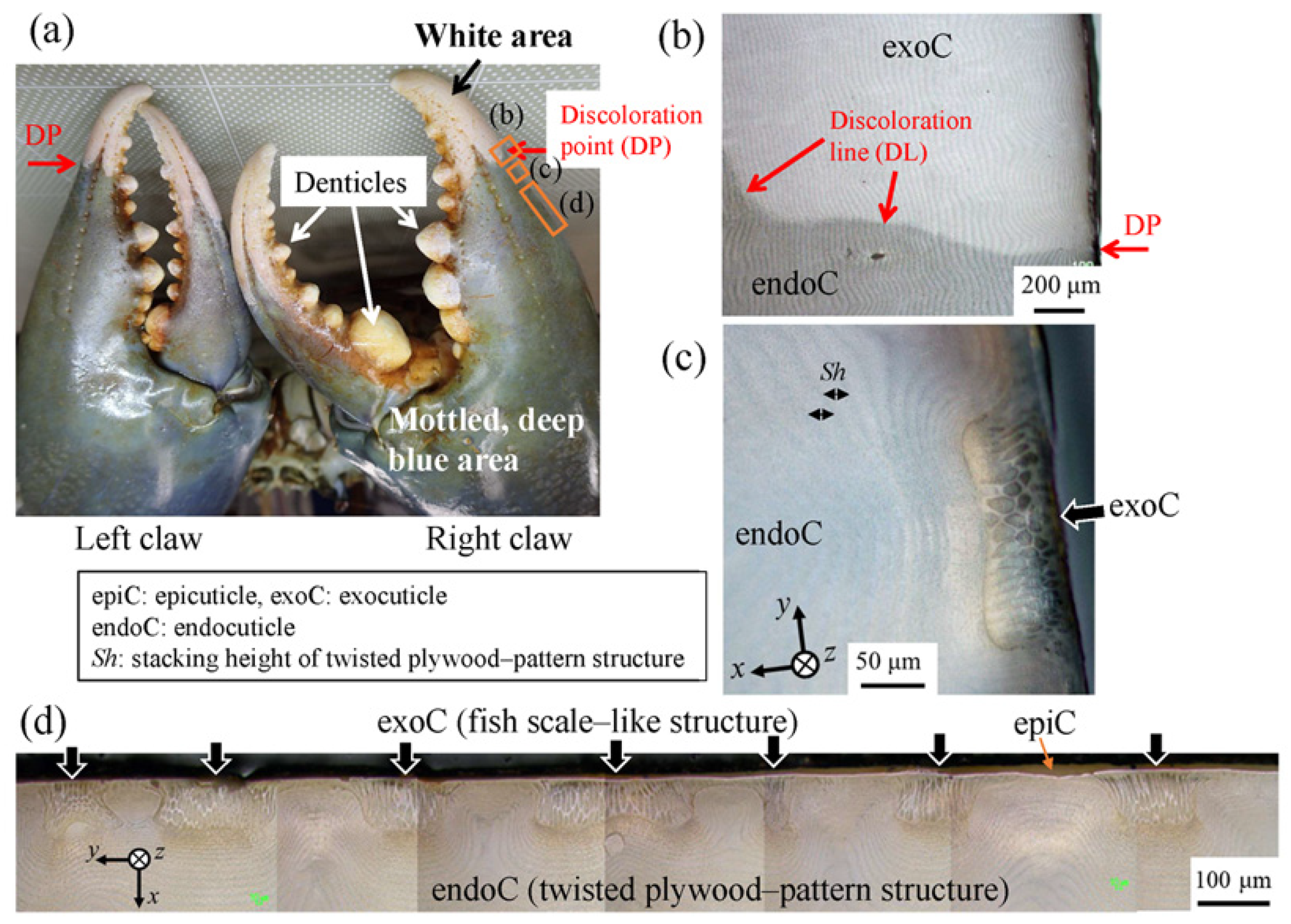
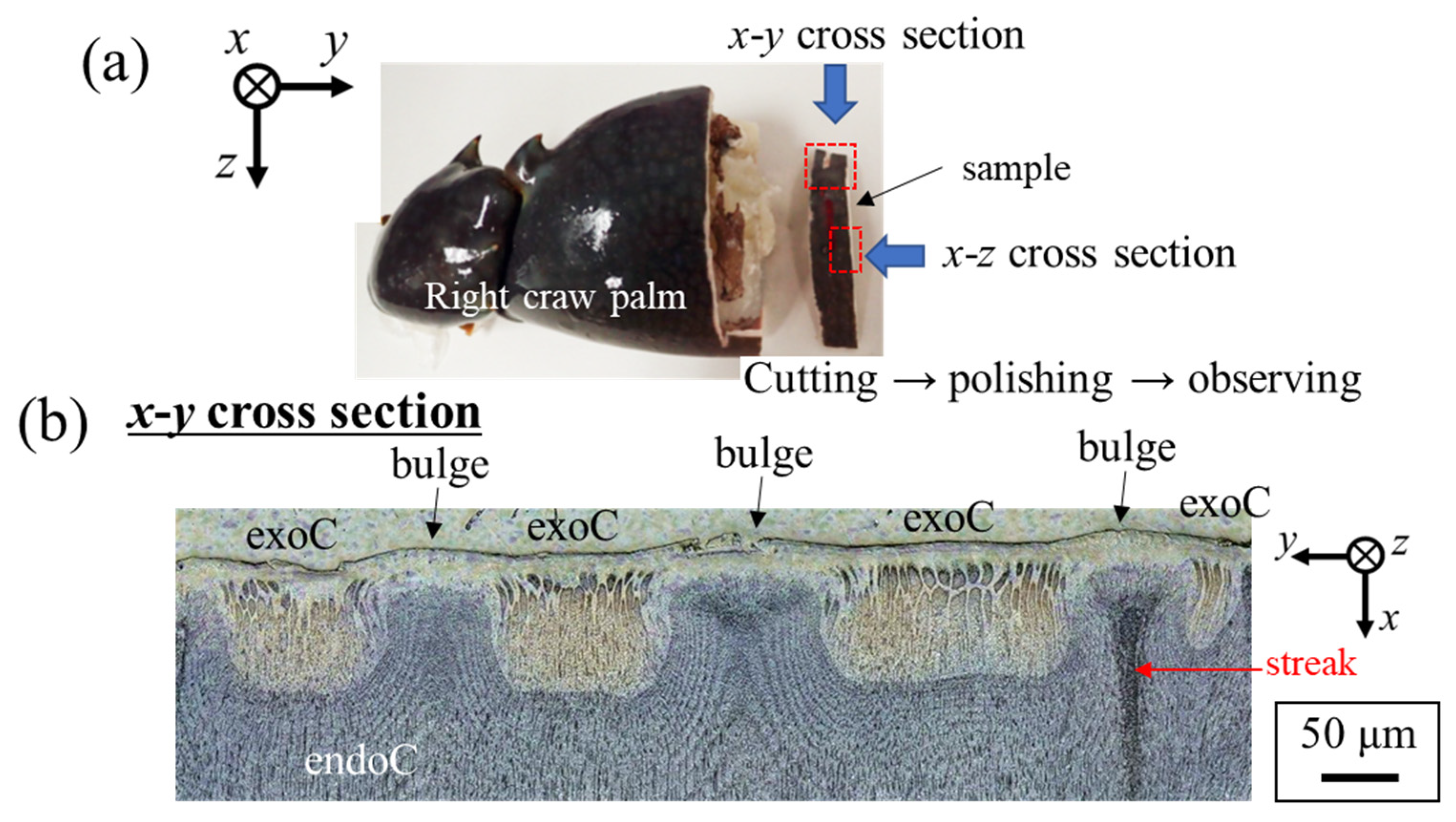
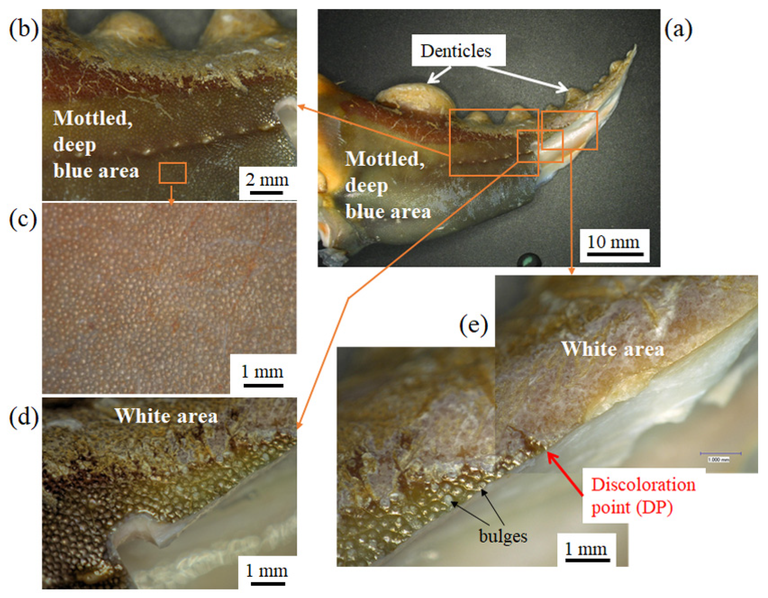
3.1. Surface Morphology

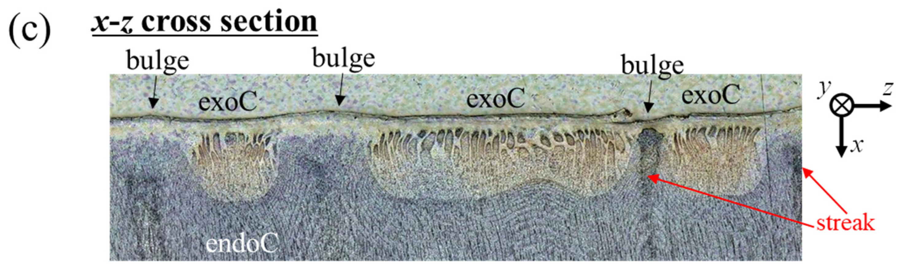
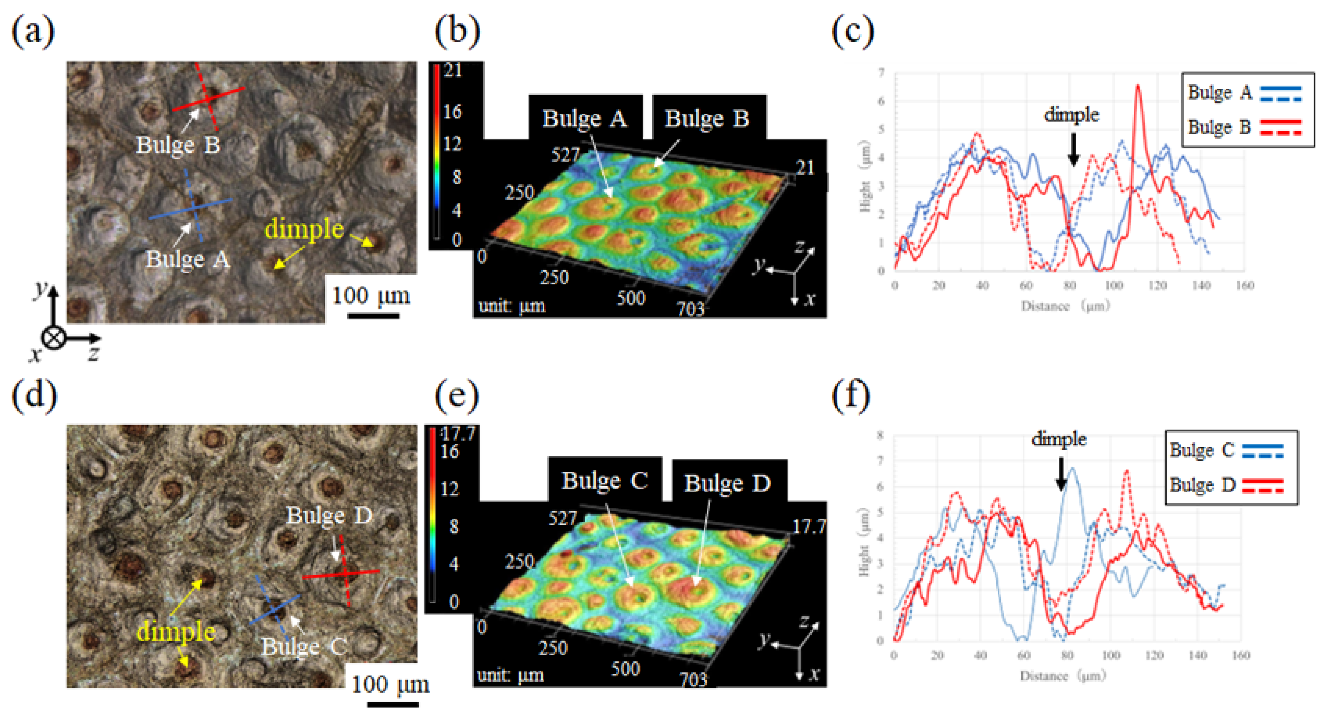
3.1.1. Fine Bulges on the Exoskeleton Surface

Figure 1d shows an optical micrograph (OM) of a relatively wide region near the surface in the blue area. This was created by merging multiple OMs. The exoC of the fish-scale–like tissue as shown in Figure 1c existed irregularly along the surface (arrows). This irregular exoC was observed throughout the blue area, and various large and small exocuticles with a thickness of 45 to 100 µm were visible, while the endoC showed striation patterns originating from the TPS [20,27]. Such microstructural features were also observed in the palm under the claw fingers and were similar in the x-y and x-z planes (Figure 2). Notice that there is a bulge on the surface between one exoC and another. In the bulge areas, the plywood layers gently curve toward the outer surface, where they proceed perpendicularly, as shown in Figure 1d and Figure 2b,c. The striped pattern was curved and blocked by the exoC and changed to a pattern perpendicular to the surface.
Figure 3 shows digital micrographs of the surface of a movable finger that was partially destroyed for fracture-surface observation. The surface is divided into a white area and a blue area. The major difference between the two areas is that only the blue surface area has bulges of several hundred microns in diameter. This difference was also observed on the front (blue area) and back (white area) of the carapace surface (Figure S2 of the supporting material), and it was confirmed on the claw surfaces of two other mud crabs (Figure S2). In other words, the presence of these bulges on the blue exoskeleton surface is a universal fact.

3.1.2. Surface Analysis of the Exoskeleton and Pore-Canal Tube

Figure 4a,c show the surface of the sample blue area observed through a laser microscope, and Figure 4b,d show the relationship between the outer surface and the cross section corresponding to the fracture surface. There are many bulges on the outer surface, and the exoC exists between these bulges. Therefore, the exoC existed irregularly on the surface in the cross section vertical to the surface (Figure 1d and Figure 2b,c). The white streaks are observed on the fracture surfaces, and they penetrate the exoskeleton. Dimples seen at the center of the bulge were more pronounced with increased drying time.
The surface bulges of two samples placed in the air for 3 months were analyzed using a laser scanning microscope. The results are shown in Figure 5. Although not shown here, similar analyses were performed for different locations on the surface of the same sample. The heights and diameters of these bulges were 5–23 µm and 90–146 µm, respectively. The sizes of the dimples in the center of the bulges seen clearly in the dried samples were 14–47 μm.

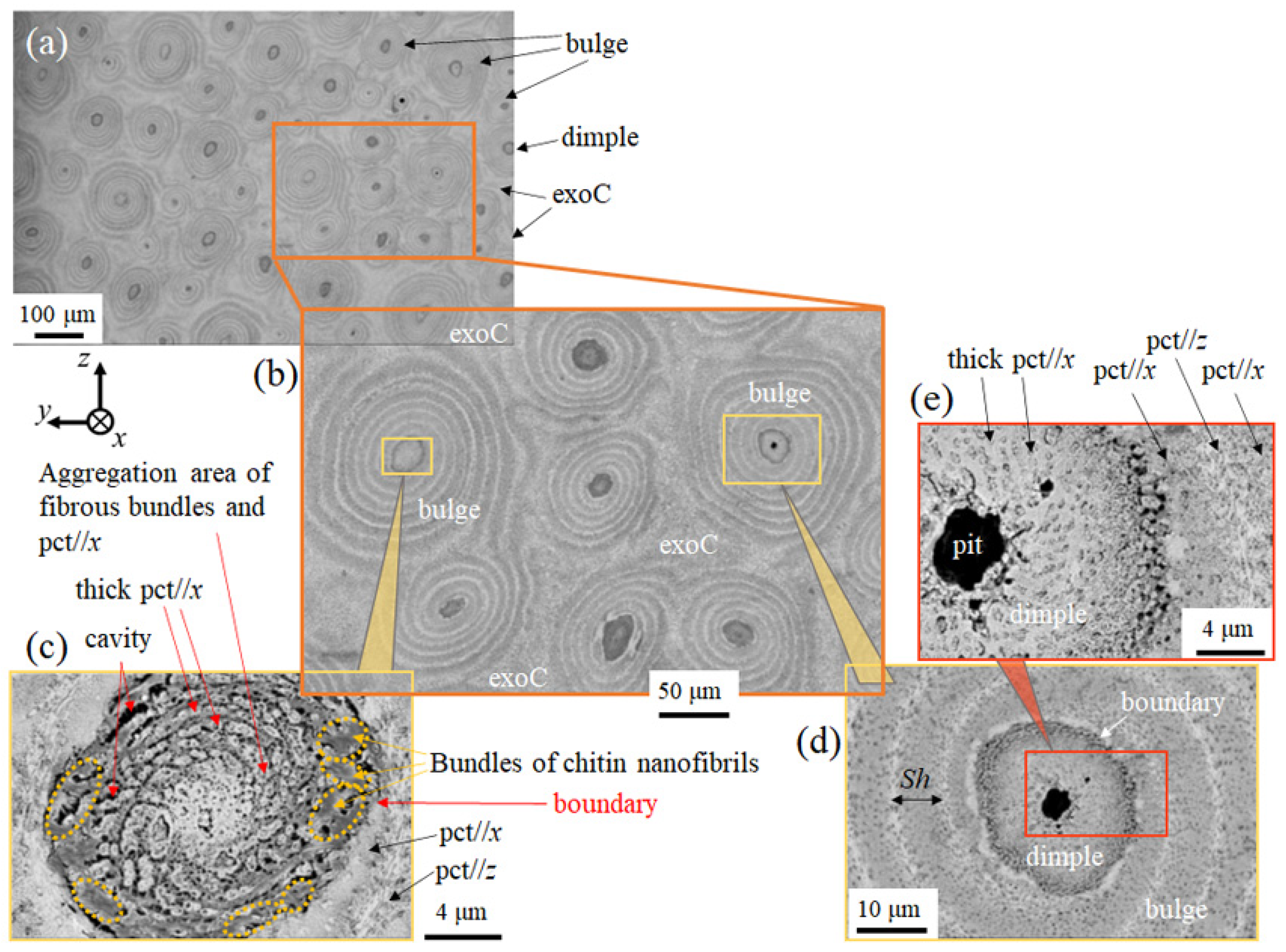
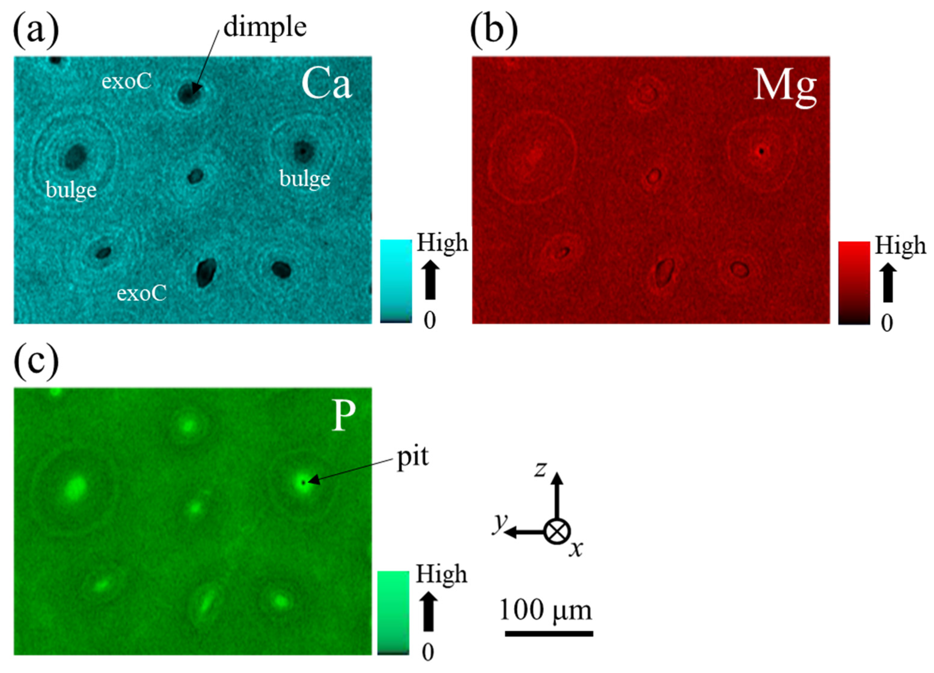
3.1.3. Microstructures of Fine Bulges and Chemical Composition

SEM images of a cross section of the surface polished transversely through the exoC and endoC, as seen in Figure 1d and Figure 2b,c, are shown in Figure 6. On the transverse section, the tissue structures are divided into bulges, dimples, and the exoC, and the bulges look like the growth rings of a tree. The ring spacing denotes the stacking height (Sh) of the TPS. In the center of the bulge corresponding to the dimple, a tissue structure different from the growth-ring pattern was visible. In Figure 6c, near the boundary between the bulge and the dimple (dashed red line), a pct or pc//x and pct//z were present on the bulge side, and chitin nanofibers were observed on the dimple side (dashed orange line). At the center of the dimple, a thick pct//x and some cavities (black) were observed, and these pcts//x appear to be aligned in a circular shape. In the center of one bulge shown in Figure 6d,e, a pit with a diameter of 4 μm was clearly observed. The size of the dimple and the tissue structure near the boundary are in agreement with those in Figure 6c.
Figure 7 shows EDS maps for the region shown in Figure 6b. There was almost no calcium (Ca) in the dimple; conversely, the amounts of phosphorus (P) and magnesium (Mg) were high. In short, the dimple seen in the center of the bulge is a canal tube formed by organic matter in which thick pcts//x connected to cells are gathered. These tubes penetrate the exoskeleton surface (Figure 4b–d), appearing as white streaks on the fracture surface (Figure 4b,d) and as black or white streaks on the polishing surface (Figure 2). The clear appearance of the dimple with increased drying time shown in Figure 4 and Figure 5 is due to shrinkage, which depends on the drying of the organic matter.

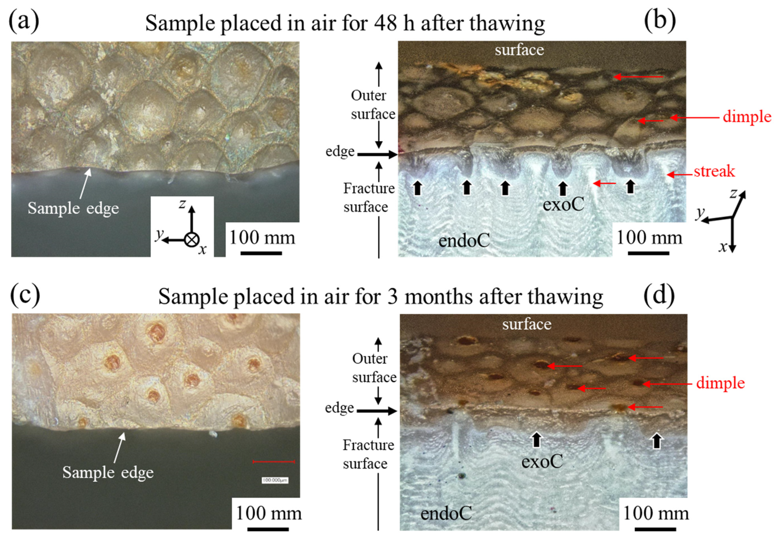
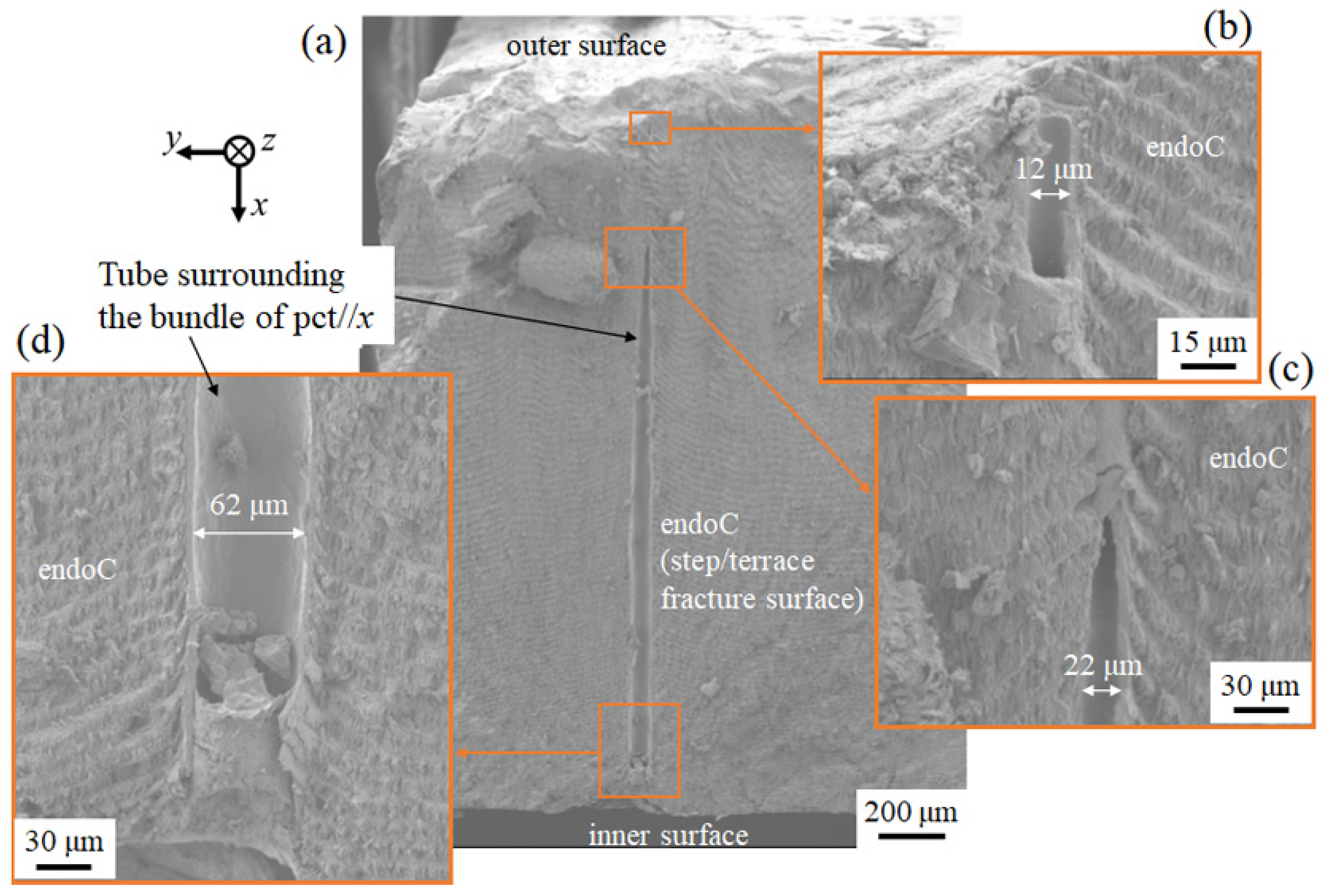
3.1.4. Fracture Surface

Figure 8 shows SEM images of the fracture surface in the blue area. The SEM images of another sample were also added to Figure S3 in the supporting material. Fortunately, as a result of taking some samples and observing the fracture surface, a thick tube cross section perpendicular to the surface was observed throughout the exoskeleton. In the fracture surface, an endoC was observed as a step/terrace-patterned structure originating from the TPS. A tube several microns thick surrounds the bundle of pcts//x that forms the dimple. The tube diameter is wide (62–66 µm) near the inner side and narrows (12–22 µm) toward the outer surface. That is to say, the tube corresponding to the dimple observed on the surface shown in Figure 4, Figure 5 and Figure 6 becomes thicker toward the inside. The tube has a low Ca concentration in the exoskeleton (Figure 7) and corresponds to a soft area. Normally, the surface layer of the exoskeleton is dominated by a hard exocuticle, so it is ideal that the soft tube becomes thinner toward the surface layer. The tube whose thickness changes throughout the exoskeleton may not only form fine bulges on the cuticle surface but may also be a factor in realizing a strong exoskeleton.

3.2. Fish-Scale-Like Tissue of the Exocuticle

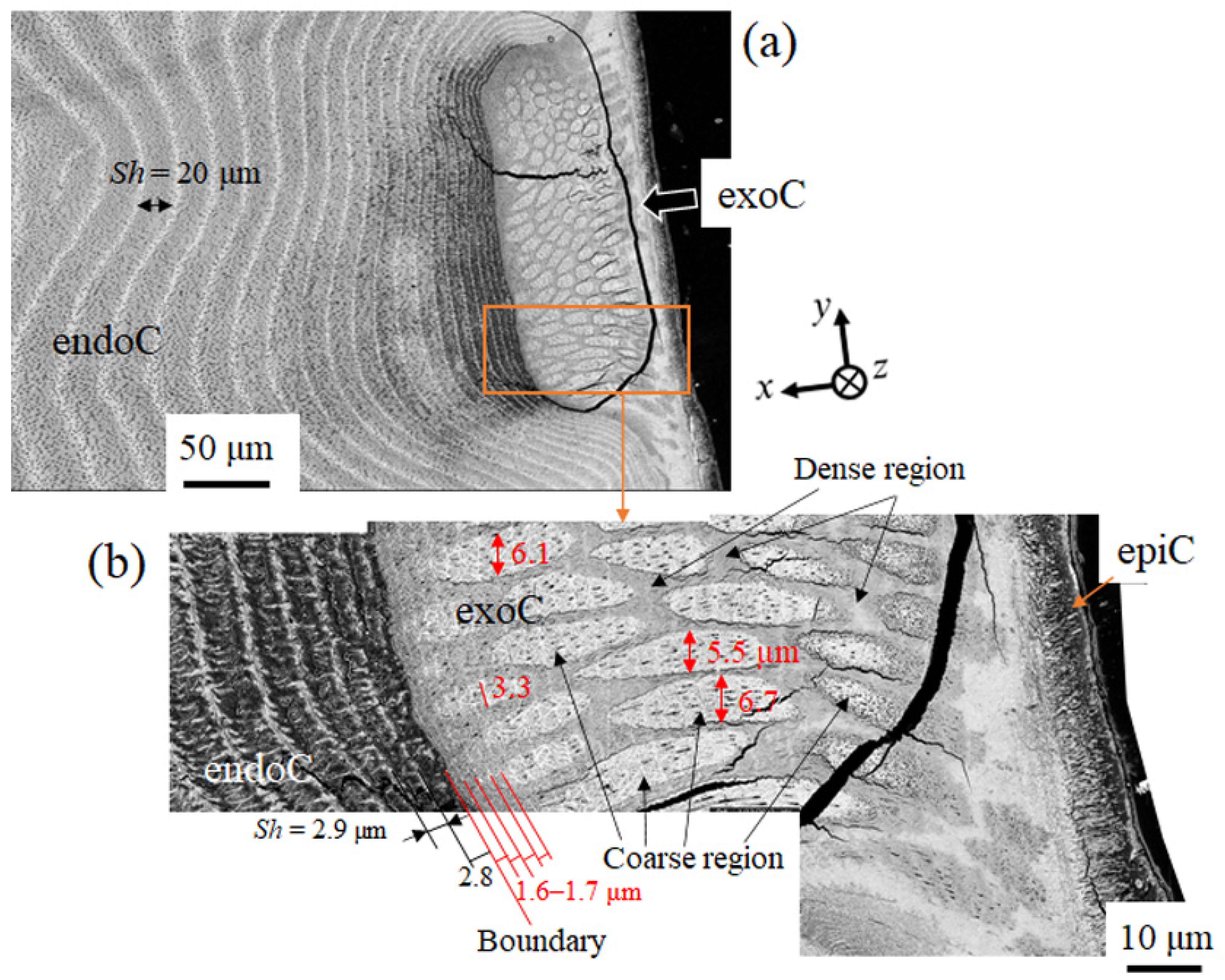
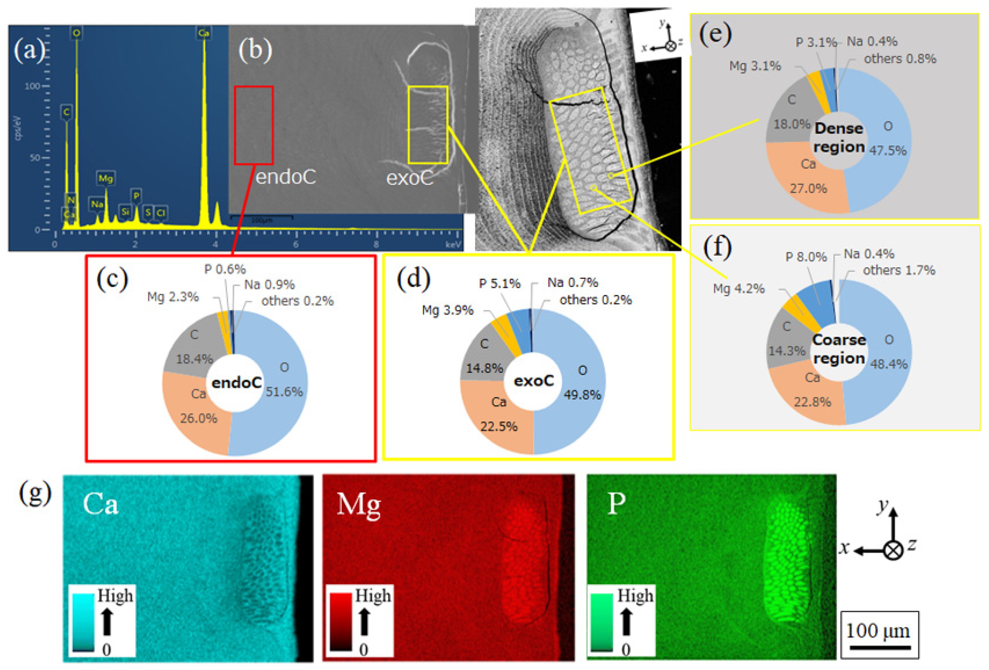
3.2.1. Microstructures and Chemical Composition

Figure 9 shows SEM micrographs of a cross section near the surface of the blue area. A distinct difference in microstructure between the exoC and endoC is visible. The endoC is striated parallel to the TPS, with the Sh gradually decreasing toward the exoC. The parts located under the exoC become very narrow and are displayed as a dark region. The exoC of the fish-scale–like tissue consists of a coarse region with many black spots extending normally to the surface and a dense region between them, as shown in Figure 1c,d and Figure 2b,c. The width of the coarse region is 3–7 µm, but some circular ones of similar size can also be observed in Figure 9a. In the enlarged image shown in Figure 9b, a very narrow striation with a Sh of 1.6–1.7 µm can be observed near the endoC even in the exoC. An epicuticle 6–7 µm thick consisting of tissue oriented perpendicularly to the surface is also observed.
The EDS results are summarized in Figure 10. The main components—calcium (Ca), magnesium (Mg), phosphorus (P), carbon (C), and oxygen (O)—and minor ones—sodium (Na), chloride (Cl-), nitrogen (N), sulfur (S), and aluminum (Al)—were found in the analysis. This result was the same as that for the exoskeleton with a white surface [27]. The area scan results for Ca, C, Mg, and P show differences in the concentrations at each layer for the exoC and endoC (Figure 10c,d). Curiously, the Ca concentrations in the exoC area are smaller than those in the endoC area. In contrast, the concentrations of Mg and P are higher in the exoC area. This is due to the heterogeneous tissue structure of the exoC. Point EDS analysis was performed for the coarse and dense regions to confirm the compositional heterogeneity associated with the fish-scale–like tissue of the exoC. Figure 10e shows the result for the dense region, and Figure 10f shows the result for the coarse region. The concentration of Ca in the dense region is higher than that in the coarse region, while the concentrations of Mg and P are lower. Surprisingly, the P concentrations in the coarse region are more than 2.5 times higher than those in the dense region. The EDS maps of Ca, Mg, and P in Figure 10g clearly show compositional non-uniformity in the exoC and compositional uniformity in the endoC.

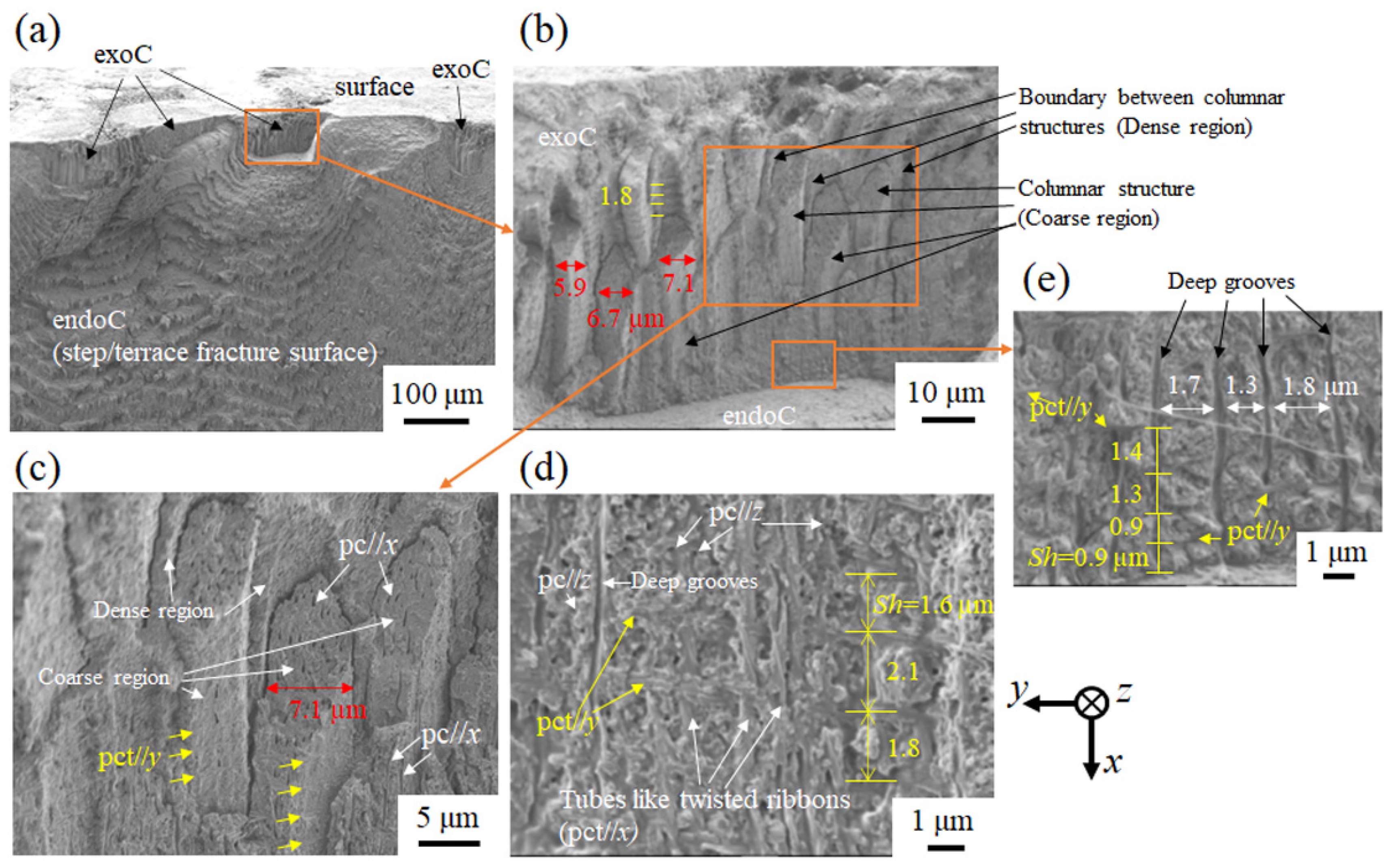
3.2.2. Fracture Surface

The difference in tissue between the exoC and endoC can be clearly observed even on the fracture surface (Figure 11). The fracture surface is divided into the exoC, with a fish-scale-like structure, and the endoC, with a step/terrace-patterned structure. In the exoC, columnar structures 5–7 µm wide that extend toward the surface from the boundary between the exoC and the endoC are seen (Figure 11b); these structures have many pore canals parallel to the x direction (pcs//x) (Figure 11c). The tubes parallel to x are visible like twisted ribbons, and the pcts//y and pcs//z normal to it are on the columnar structure face (Figure 11c,d). The presence of such tubes, like twisted ribbons, in the exoskeleton has been reported in other crustaceans [20,29]. That is, the columnar structures correspond to the coarse region shown in Figure 9, and the area between these corresponds to a dense region. Interestingly, pcts//y (yellow arrows in Figure 11b–e) were observed on the coarse region face (Figure 11c,d) and near the boundary between the exoC and the endoC (Figure 11e). Furthermore, lines 1.8 µm away from and parallel to the surface that seem to be pcts//y were also found on the face of the place where a piece of the coarse region disappeared when the claw sample was destroyed (yellow lines in Figure 11b). Generally, the pct//y spacing observed on the fracture surface corresponds to the Sh, and these appear as streaks parallel to the surface on the polished surface [10,14,15,20,23]. The Sh measured on the fracture surface shown in Figure 11 corresponds to that measured on the polished surface of shown in Figure 9. In short, macroscopically, there is a clear difference between exoC and endoC tissue, but the microstructure in the blue exoskeleton of the mud crab has a TPS. However, the Sh of the exoC is much shorter than that of the endoC, and the proportion of pc//x differs depending on the location. The coarse region for many pcs//x is a columnar structure, with a diameter of 5–7 µm, extending from the boundary to the outer surface, with a dense region between them. As a result, fish-scale–like tissue is observed as the exocuticle on the surface layer.

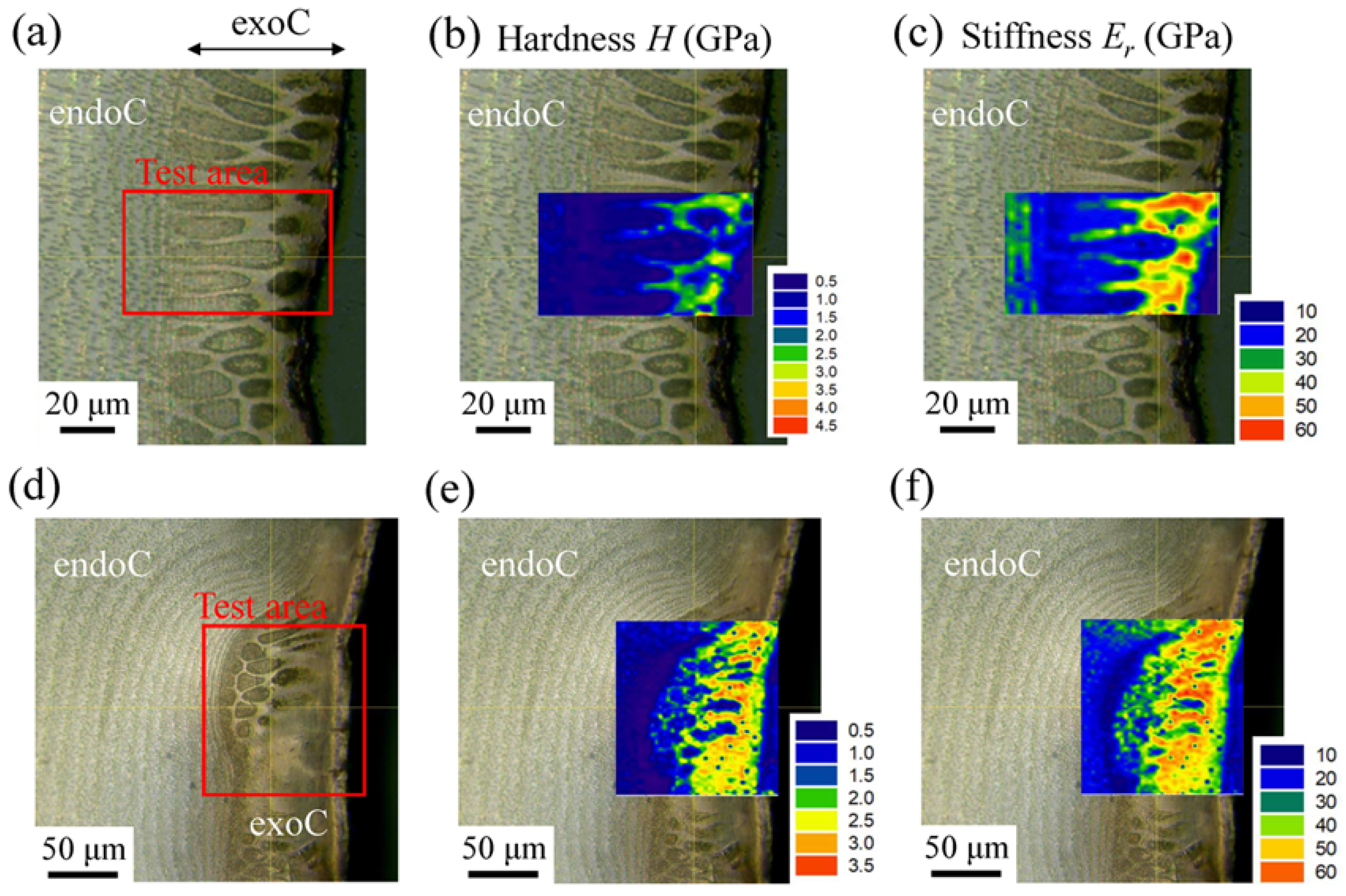
3.2.3. Mechanical Properties

The differences in the percentage of pores and composition in the two regions of the exoC should be reflected in the differences in mechanical properties. However, as shown in Figure 9, Figure 10 and Figure 11, each region is narrow, and accurate properties cannot be measured using a normal hardness test such as the Vickers test due to the influence of the indentation size. The mechanical properties in the two regions were examined via nanoindentation tests. The tests were conducted 20 times for the coarse region and 12 times for the dense region. The locations of the indentations after these tests are shown in Figure S4 in the supporting material. Since some data for each region in which the indentations were not accurately performed have been removed, the properties show the (average values) ± (standard deviations) of 15 times for the coarse region and 9 times for the dense region. In the coarse region, the H and Er were 0.55 ± 0.18 and 18.12 ± 3.59 (GPa), respectively. In the dense region, H = 1.54 ± 0.55 and Er =23.94 ± 4.83 (GPa). The hardness in the dense region is 2.8 times that in the coarse region, and the modulus is 1.3 times that in the coarse region. The modulus is also associated with the volume of the test area, so there may not have been a significant difference in modulus as compared with hardness. The dense regions are streaky between the coarse regions, as shown in Figure 9 and Figure 11, and this region was slightly larger than the indentation size. The indentation sizes converted from the projected contact area of the indentation were 3.54–6.69 μm in the coarse region and 2.18–3.61 μm in the dense region. As compared to the endoC with almost constant properties (H = 1.0, Er = 30 GPa) reported in the previous paper [27], the hardness of the dense region was higher, and that in the coarse region was lower. However, the hardness of the dense region was lower than that of the exoC (H = 2.0, Er = 48 GPa) in the white area.
Attempts were made to create a map of mechanical properties to clarify the heterogeneity of the H and Er within the exoC. However, to reduce the effect of indentation size on mapping, the Fmax in the tests was set to 0.5 mN, which is 1/10 that of the previous test. The H and Er maps are shown in Figure 12. These show the results of conducting a nanoindentation test over a wide range on the two exocuticles observed on the surface layer of the blue area. The distribution of the mechanical properties in the exoC with fish-scale–like tissue includes the H and Er that are high in the dense region and low in the coarse region. The contour maps of the mechanical properties shown in Figure 12 are consistent with the EDS maps shown in Figure 10g.

3.3. Bulges on the Mottled, Deep-Blue Surface of the Exoskeleton

The irregularly present exocuticles 45 to 100 µm thick on the surface layer of the mottled, deep-blue exoskeleton cross section in the mud crab’s claw were strongly related to the unevenness of the exoskeleton surface. The bulges—seen only on the mottled, deep-blue surface—varied from 90 to 146 µm in diameter and 5 to 23 µm in height. Such a bulge in the exoskeleton surface of the crab has also been observed in the red, blue, and white shells of the blue crab [24] and in brown crab shells [20], which have color on the exoskeleton surface. The presence of an exoC on the colored exoskeleton is thought to play an important role in forming bulges of various sizes on the surface of the exoskeleton. Only at the center of this bulge did a tube penetrate the exoskeleton. The tube bundled the many pcts//x connected to cells, and this tube was also confirmed on the fracture surface (see Figure 8 and Figure S3 in the supporting material). The tube diameter decreased from the inner surface to the outer surface. Such thick tubes have been observed as deep, irregular grooves on the fracture surface of the exoskeletons of lobsters [30] and coconut crabs [10,15]. The diameter of this tube was much larger in the mud crab than in the coconut crab but smaller than in the lobster. These differences may depend on whether the habitat is terrestrial, shallow, or in deep seawater. The shells of crabs that inhabit relatively shallow bays are not dirty, and no sessile organisms are attached to the shells. Due to the presence of fine bulges on the exoskeleton surface and thick tubes with many pcts//x that penetrate the bulge peaks, it is highly unlikely that dirt will adhere to the exoskeleton. This is like a “self-cleaning surface,” called the lotus effect, found on the surface of some organisms and plants [31,32]. The lotus effect is created through the synergistic effect of the unevenness of the surface and the wax-like substance secreted from the tip. It is not surprising that such functions are found on the surface of the crab’s exoskeleton. Many crabs take Ca into their bodies by eating their own shells after molting. It would not be desirable for crabs to eat shells with various sessile organisms attached. Moreover, the unevenness of the surface has the effect of reducing the contact area with the outside and dispersing the force applied to the exoskeleton [22,33]. This is like the role of denticles on the pinching side of a crab’s claw [22]. For crabs, the fine bulges on the surface, and the presence of the many pore-canal tubes that penetrate those bulge peaks, are likely important for maintaining a clean and strong shell.

4. Conclusions

The relationship between the bulge on the blue exoskeleton surface and the internal tissue in the mud crab’s claw was investigated. The endoC, which occupies most of the exoskeleton, shows a striped pattern parallel to the surface derived from the TPS; the pattern was curved and blocked by the exoC, and it changed to a pattern perpendicular to the surface. The bulges on the surface formed at the changed location. In short, the bulges exist between two exocuticles. At the apex of the bulges, there was a thick tube surrounding the bundles of many pore canals penetrating the exoskeleton. On the other hand, the exoC had a heterogeneous tissue structure in the coarse region extending normally to the surface, and a dense region between the coarse regions. The P and Mg concentrations were high in the coarse region, and the Ca concentration was high in the dense region. As a result, the distribution of the mechanical properties inside the exocuticle and its heterogeneity were clarified through the hardness and modulus maps generated from the nanoindentation test.

Supplementary Materials

The following supporting information can be downloaded at: https://www.mdpi.com/article/10.3390/min12121607/s1, Figure S1: Digital micrographs of the carapace surface of the mud crab observed through a digital microscope (VHX-900, Keyence Corporation, Osaka, Japan). Many bulges several hundred microns in diameter are observed only on the surface of the mottled, deep-blue area. These bulges were also confirmed on the claw surfaces of the mud crab shown in Figure 3. No bulge is visible on the white exoskeleton surface on the back side of the carapace. Figure S2: Digital micrographs of the claw surface of two other mud crabs observed through a digital microscope (VHX-900, Keyence Corporation, Osaka, Japan). Many bulges several hundred microns in diameter are observed only on the surface of the mottled, deep-blue area. These bulges were also confirmed on the surface of the claw and carapace of the mud crab (body weight 1265 g), as shown in Figure 3 and Figure S1. Figure S3: Scanning electron microscope images of the fracture surface in the mottled, deep-blue exoskeleton. Figure S4: Hardness, H, and elastic modulus, Er, at (a) coarse regions corresponding to the columnar structure and (b) dense regions between columnar structures obtained by nanoindentation tests (maximum force = 5 mN, loading time = 5 s). The tests were conducted 15 times for the coarse region and 10 times for the dense region. The properties are the average values, including their standard deviation. Red circles in Figures show indentations after tests. Some data, for which the indentations were not accurately embedded in each region, have been removed.

Author Contributions

Conceptualization, T.I.; methodology, T.I.; software, T.I. and E.K.; validation, T.I.; investigation, T.I.; resources, T.I. and K.N.; data curation, T.I., E.K. and Y.H.; writing—original draft preparation, T.I.; writing—review and editing, T.I., E.K., Y.H. and K.N.; visualization, T.I.; supervision, T.I.; project administration, T.I.; funding acquisition, T.I. All authors have read and agreed to the published version of the manuscript.

Funding

This research was funded by JSPS KAKENHI Grant Number JP21H04537. The grant is greatly appreciated.

Data Availability Statement

Not applicable.

Acknowledgments

We would like to thank S. Oka for obtaining some of the samples, T. Hara for advice on microstructural observation, M. Sakano for supporting the analysis with laser microscopy, and Y. Kashihara for creating the illustrations.

Conflicts of Interest

The authors declare no conflict of interest.

References

  1. Collado, A.G.; Blanco, J.M.; Gupta, M.K.; Vicentea, R.D. Advances in polymers based Multi-Material Additive-Manufacturing Techniques: State-of-art review on properties and applications. Addit. Manuf. 2022, 50, 102577. [Google Scholar] [CrossRef]
  2. Tiismus, H.; Kallaste, A.; Vaimann, T.; Rassõlkin, A. State of the art of additively manufactured electromagnetic materials for topology optimized electrical machines. Addit. Manuf. 2022, 55, 102778. [Google Scholar] [CrossRef]
  3. Zhou, Y. The Application of Ultrasound in 3D Bio-Printing. Molecules 2016, 21, 590. [Google Scholar] [CrossRef] [PubMed]
  4. Pradhan, S.; Brooks, A.K.; Yadavalli, V.K. Nature-derived materials for the fabrication of functional biodevices. Mater. Today Bio 2020, 7, 100065. [Google Scholar] [CrossRef] [PubMed]
  5. Islam, M.K.; Hazell, P.J.; Escobedo, J.P.; Wang, H. Biomimetic armour design strategies for additive manufacturing: A review. Mater. Des. 2021, 205, 109730. [Google Scholar] [CrossRef]
  6. Huang, W.; Restrepo, D.; Jung, J.-Y.; Su, F.Y.; Liu, Z.; Ritchie, R.O.; McKittrick, J.; Zavattieri, P.; Kisailus, D. Multiscale Toughening Mechanisms in Biological Materials and Bioinspired Designs. Adv. Mater. 2019, 31, 1901561. [Google Scholar] [CrossRef]
  7. Zhang, B.; Han, Q.; Zhang, J.; Han, Z.; Niu, S.; Ren, L. Advanced bio-inspired structural materials: Local properties determine overall performance. Mater. Today. 2020, 41, 177–199. [Google Scholar] [CrossRef]
  8. Sun, Y.; Tian, W.; Zhang, T.; Chen, P.; Li, M. Strength and toughness enhancement in 3d printing via bioinspired tool path. Mater. Des. 2020, 185, 108239. [Google Scholar] [CrossRef]
  9. Huber, D.R.; Eason, T.G.; Hueter, R.E.; Motta, P.J. Analysis of the bite force and mechanical design of the feeding mechanism of the durophagous horn shark Heterodontus francisci. J. Exp. Biol. 2005, 208, 3553–3571. [Google Scholar] [CrossRef] [Green Version]
  10. Inoue, T.; Oka, S.; Hara, T. Three-dimensional microstructure of robust claw of coconut crab, one of the largest terrestrial crustaceans. Mater. Des. 2021, 206, 109765. [Google Scholar] [CrossRef]
  11. Taylor, G.M. Maximum force production: Why are crabs so strong? Proc. Biol. Sci. 2000, 267, 1475–1480. [Google Scholar] [CrossRef] [PubMed]
  12. Wu, K.; Song, Z.; Zhang, S.; Ni, Y.; Cai, S.; Gong, X.; He, L.; Yu, S. Discontinuous fibrous Bouligand architecture enabling formidable fracture resistance with crack orientation insensitivity. Proc. Natl. Acad. Sci. USA 2020, 117, 15465–15472. [Google Scholar] [CrossRef] [PubMed]
  13. Natarajan, B.; Gilman, J.W. Bioinspired Bouligand cellulose nanocrystal composites: A review of mechanical properties. Phil. Trans. R. Soc. A 2017, 376, 20170050. [Google Scholar] [CrossRef] [PubMed] [Green Version]
  14. Raabe, D.; Sachs, C.; Romano, P. The crustacean exoskeleton as an example of a structurally and mechanically graded biological nanocomposite material. Acta Mater. 2005, 53, 4281–4292. [Google Scholar] [CrossRef]
  15. Inoue, T.; Hara, T.; Nakazato, K.; Oka, S. Superior mechanical resistance in the exoskeleton of the coconut crab, Birgus latro. Mater. Today Bio 2021, 12, 100132. [Google Scholar] [CrossRef]
  16. Ma, Y.; Guo, C.; Dai, N.; Shen, J.; Guan, J. Structural characterization and regulation of the mechanical properties of the carapace cuticle in tri-spine horseshoe crab (Tachypleus tridentatus). J. Mech. Behav. Biomed. Mater. 2022, 125, 104954. [Google Scholar] [CrossRef]
  17. Cheng, L.; Thomas, A.; Glancey, J.L.; Karlsson, A.M. Mechanical behavior of bio-inspired laminated composites. Compos. Part A Appl. Sci. Manuf. 2011, 42, 211–220. [Google Scholar] [CrossRef] [Green Version]
  18. Yano, I. A histochemical study on the exocuticle with respect to its calcification and associated epidermal cells in a shore crab. Bull. Jpn. Soc. Sci. Fish. 1972, 38, 733–739. [Google Scholar] [CrossRef]
  19. Rose, R.; Dillaman, R. The Structure and Calcification of the Crustacean Cuticle. Am. Zool. 1984, 24, 893–909. [Google Scholar] [CrossRef]
  20. Fabritius, H.-O.; Karsten, E.S.; Balasundaram, K.; Hild, S.; Huemer, K.; Raabe, D. Correlation of structure, composition and local mechanical properties in the dorsal carapace of the edible crab Cancer pagurus. Z. Kristallogr. 2012, 227, 766–776. [Google Scholar] [CrossRef]
  21. Fabritius, H.-O.; Sachs, C.; Triguero, P.R.; Raabe, D. Influence of structural principles on the mechanics of a biological fiber-based composite material with hierarchical organization: The exoskeleton of the lobster homarus americanus. Adv. Mater. 2009, 21, 391–400. [Google Scholar] [CrossRef]
  22. Inoue, T.; Oka, S.; Nakazato, K.; Hara, T. Structural changes and mechanical resistance of claws and denticles in coconut crabs of different sizes. Biology 2021, 10, 1304. [Google Scholar] [CrossRef] [PubMed]
  23. Inoue, T.; Oka, S.; Nakazato, K.; Hara, T. Columnar Structure of Claw Denticles in the Coconut Crab, Birgus latro. Minerals 2022, 12, 274. [Google Scholar] [CrossRef]
  24. Nekvapil, F.; Pinzaru, S.C.; Barbu-Tudoran, L.; Suciu, M.; Glamuzina, B.; Tamaș, T.; Chiș, V. Color-specific porosity in double pigmented natural 3d-nanoarchitectures of blue crab shell. Sci. Rep. 2020, 10, 3019. [Google Scholar] [CrossRef] [Green Version]
  25. Lee, H.A.-H.S.Y.; Meynecke, J.-Q.; Diele, K.; Nordhaus, I.; Wolff, M. Life-history, movement, and habitat use of Scylla serrata (Decapoda, Portunidae): Current knowledge and future challenges. Hydrobiologia 2016, 763, 5–21. [Google Scholar] [CrossRef] [Green Version]
  26. Waugh, D.A.; Feldmann, R.M.; Schroeder, A.M.; Mutel, M.H. Differential cuticle architecture and its preservation in fossil and extant Callinectes and Scylla claws. J. Crustacean Biol. 2006, 26, 271–282. [Google Scholar] [CrossRef] [Green Version]
  27. Inoue, T.; Hiroto, T.; Hara, Y.; Nakazato, K.; Oka, S. Exoskeleton of huge claws of mud crab, Scylla serrata, Tissue structure and mechanical properties. J. Mater. Sci. 2022. [Google Scholar]
  28. Amini, S.; Miserez, A. Wear and abrasion resistance selection maps of biological materials. Acta Biomater. 2013, 9, 7895–7907. [Google Scholar] [CrossRef]
  29. Chen, P.-Y.; Lin, A.Y.; McKittrick, J.; Meyers, M.A. Structure and mechanical properties of crab exoskeletons. Acta Biomater. 2008, 4, 587–596. [Google Scholar] [CrossRef]
  30. Sachs, C.; Fabritius, H.; Raabe, D. Experimental investigation of the elastic–plastic deformation of mineralized lobster cuticle by digital image correlation. J. Struct. Biol. 2006, 155, 409–425. [Google Scholar] [CrossRef]
  31. Barthlott, W.; Mail, M.; Bhushan, B.; Koch, K. Plant Surfaces: Structures and Functions for Biomimetic Innovations. Nano-Micro Lett. 2017, 9, 1265–1305. [Google Scholar] [CrossRef] [PubMed]
  32. Darmanin, T.; Guittard, F. Superhydrophobic and superoleophobic properties in nature. Mater. Today 2015, 18, 273–285. [Google Scholar] [CrossRef]
  33. Inoue, T.; Yin, F.; Kimura, Y.; Tsuzaki, K.; Ochiai, S. Delamination Effect on Impact Properties of Ultrafine-Grained Low-Carbon Steel Processed by Warm Caliber Rolling. Met. Mater. Trans. A 2010, 41, 341–355. [Google Scholar] [CrossRef]
Figure 1. (a) Claws of a mud crab and optical micrographs (OMs) of a cross section of (b) the white area and (c,d) the mottled, deep-blue area. Here, (d) shows the wide range on the mottled, deep-blue surface, and arrows indicate exocuticles that are irregularly present on the surface.
Minerals 12 01607 g001
Figure 2. (a) Palm of the right claw of the mud crab used, and laser scanning microscope images of cross sections of (b) the x-y plane and (c) x-z plane on the mottled, deep-blue area observed through a 3D laser scanning microscope. Here, exoC denotes the exocuticle, and endoC denotes the endocuticle.
Minerals 12 01607 g002aMinerals 12 01607 g002b
Figure 3. (a) Digital micrographs showing the surface of the movable finger of a mud crab’s claw observed through a digital microscope (VHX-900, Keyence Corporation, Osaka, Japan). Enlarged images of the area enclosed by the rectangles in (a): (b) the mottled, deep-blue area, (d) the area between the blue and white areas, and (e) the DP area. (c) Enlarged image of the area enclosed by the rectangles in (b). Many bulges of various sizes were observed on the surface of the blue area. Here, the fingertip was broken by hitting the back of a chisel with a hammer to prepare a test piece for fracture-surface observation.
Minerals 12 01607 g003
Figure 4. (a,c) Optical micrographs of the surface of the mottled, deep-blue area of two samples placed in air for 48 h and 3 months after thawing, respectively, and (b,d) high-dynamic range (HDR) images taken with the sample tilted slightly.
Minerals 12 01607 g004
Figure 5. (a) Laser scanning microscope image of the surface of the mottled, deep-blue samples placed in air for 3 months after thawing, (b) 3D color map showing bulges on the surface, and (c) line profiles in two orthogonal directions on two bulges, A and B in (a). (d) Laser scanning microscope image of the surface of another sample placed in air for 3 months after thawing, (e) 3D color map showing bulges on the surface, and (f) line profiles in two orthogonal directions on two bulges, C and D in (d).
Minerals 12 01607 g005
Figure 6. SEM images of a transverse section through the exocuticle layer on the mottled, deep-blue exoskeleton: (a) wide area including many bulges, (b) enlarged view of the area surrounded by rectangle in (a), (c) enlarged view of the bulge top surrounded by a rectangle in (b), (d) enlarged views of the bulge top with the pit surrounded by a rectangle in (b), and (e) enlarged view surrounded by a rectangle in (d). Here, Sh denotes the stacking height of the twisted plywood structure.
Minerals 12 01607 g006
Figure 7. EDS maps showing the distribution of (a) calcium (Ca), (b) magnesium (Mg), and (c) phosphorus (P) in a transverse section of the mottled, deep-blue exoskeleton. The SEM image for this area is shown in Figure 6b.
Minerals 12 01607 g007
Figure 8. (a) SEM images of the fracture surface in the mottled, deep-blue exoskeleton. Enlarged SEM images of the area enclosed by rectangles in (a), (b) endocuticle near the outer surface, (c) endocuticle, and (d) endocuticle near the inner surface.
Minerals 12 01607 g008
Figure 9. (a) SEM image of a cross section of the mottled, deep-blue surface and (b) enlarged view of the exocuticle surrounded by a rectangle in (a).
Minerals 12 01607 g009
Figure 10. (a) X-ray spectrum showing the presence of C, O, Mg, P, Ca, Na, Si, S, N, and Cl. (b) SEM image showing the area near the surface, including the exocuticle. (cf) EDS-area scan results for the region surrounded by (c) a red rectangle and (d) a yellow rectangle in (b), and EDS point results for (e) the dense region and (f) the coarse region. Here, concentrations of C and O were shown as reference data due to sample contamination. (g) EDS maps showing the distributions of Ca, Mg, and P.
Minerals 12 01607 g010
Figure 11. SEM images of the fracture surface in the mottled, deep-blue area. (a) Near the surface. (b,c) Enlarged views of areas surrounded by rectangles in (a,b). (d) Enlarged view of the columnar structure face. (e) Enlarged view near the boundary between the exo- and endocuticle.
Minerals 12 01607 g011
Figure 12. (a) OM showing the area near the mottled, deep-blue surface, including the nanoindentation test area, and contour maps of the (b) hardness, H, and (c) modulus, Er, inside the exocuticle (maximum force = 0.5 mN, loading time = 0.5 s). (d) OM showing at the other exocuticle, and contour maps of the (e) H and (f) Er. Here, the test areas in (a,d) are 74 × 42 µm (38 × 22 = 836 points) and 108 × 116 µm (55 × 59 = 3245 points), respectively.
Minerals 12 01607 g012
Publisher’s Note: MDPI stays neutral with regard to jurisdictional claims in published maps and institutional affiliations.

