Article

The Effect of Clay Minerals on Fayalite Slag Structure and Refractory Brick Wear during Copper Smelting

1
Advanced Mining Technology Center, AMTC, University of Chile, Santiago 8370451, Chile
2
Department of Mining Engineering, DIMin, University of Chile, Santiago 8370451, Chile
*
Authors to whom correspondence should be addressed.
Minerals 2022, 12(11), 1431; https://doi.org/10.3390/min12111431
Submission received: 22 September 2022 / Revised: 22 October 2022 / Accepted: 8 November 2022 / Published: 10 November 2022
(This article belongs to the Special Issue Advances in Mineral Processing and Process Engineering)

Abstract

:
Metallic copper production via the pyrometallurgical route is hindered due to the increased presence of gangue in the clay minerals in copper sulfide concentrates and its unpredictable effect on this operation. In this study, the relationship between smelting copper slag composition, including the clay components and the refractory brick wear, was investigated in experimental laboratory tests. Synthetic fayalite slags doped with 2, 5, or 8 wt% high-purity kaolinite or montmorillonite were introduced into magnesia chromite refractory crucibles and melted in an electrical furnace under the controlled partial pressure of oxygen (10−8 atm) for 12 h at temperatures of 1250 and 1300 °C. After the experimental time, the crucibles were quenched in water, and the obtained samples were analyzed using the XRD, SEM, and ICP techniques. According to the results, at 1300 °C the presence of montmorillonite in the fayalite-based slag promoted infiltration through the refractory brick and increased the dissolution of the magnesia component from the hot face. In the case of the kaolinite, the infiltration was even higher, but the magnesia dissolution was delayed.

1. Introduction

The copper production process is not a unique procedure and depends on the raw materials, with copper sulfide and copper oxides being the most common in Chilean ore deposits. The reduction step size is the same for both, but thereafter, oxide minerals follow a hydrometallurgical route based on lixiviation, solvent extraction, and electrowinning. Copper production through pyrometallurgy, which is associated with copper sulfide ores, utilizes froth flotation as the concentration step and a smelting stage.
In particular, copper production is currently facing new challenges because smelters have to treat complex copper sulfide concentrates with a higher content of oxide gangue, i.e., between 6 and 10 wt%. Therefore, the effect of the impurities on the smelting operations is a relevant issue [1]. However, to date, only a few studies have focused on identifying the specific behavior of those gangue minerals during the smelting stage.
Minerals from the hydrous aluminum phyllosilicate group, often broadly classified as ‘clays’, exist as common gangue components in most sulfide ore deposits [2]. In the case of Chile, the most common clays correspond to kaolinite, montmorillonite, and illite, which are found in ore deposits in a range of 4–22 wt% [3]. As a result of their planar structure, they are mechanically dragged into the hydrophobic concentrate during the froth flotation process, with detrimental effects [4].
During the smelting stage, the dissociation of the clay minerals contained in the copper concentrate generates oxides, which are distributed in the slag phase at thermodynamic pseudo-equilibrium, changing its transport properties. When acidic oxides melt into fayalite slag, they polymerize its structure and form long polyions that increase its viscosity, making it difficult to handle, while basic oxides, such as lime and magnesia, result in the production of the opposite effect because they break the polyions into smaller structural units. The viscosity of the slag represents one of the most relevant variables in pyrometallurgy due to its direct impact on copper mechanical entrapment and refractory brick wear, affecting the OpEx of the process [1].
Magnesia chromite refractories are widely used as the refractory lining in copper smelters, and during the operation, they are in contact with the gas stream, molten slag, matte, and metallic phases. The application of other refractory types is limited to insulating purposes, and none of the tested chrome-free refractory alternatives has improved the performance of the magnesia chromite refractory bricks [5].
The refractory lining must withstand the combined thermal, chemical, and mechanical demands. Barthel described the concerns related to refractory bricks in copper smelting furnaces and categorized them according to relative importance [6]. The contact of magnesia chromite refractory bricks with the most widely used fayalite-based slag primarily leads to the dissolution of the specific phases in the brick microstructure, mainly magnesia (MgO) and alumina (Al2O3). The low viscosity significantly promotes refractory infiltration and wear, as Fahey showed in his study on refractory wear by calcium ferrite slag in continuous copper conversion [7].
In addition, increasing the use of both low-grade ore in the primary copper industry and the incorporation of recycling materials with high levels of impurities as secondary feed represents a substantial change in the operational conditions of copper smelters. This is of particular relevance for equilibrated slag, which could influence the performance of the currently approved refractory bricks.
In particular, the aim of this study was to explore how the presence of clay minerals affects the composition and structure of fayalitic slag and, consequently, to verify whether there is a relationship between this and the refractory brick wear. This study represents the first to develop a geometallurgical operational understanding to this end. Moreover, this paper hopes to encourage other similar studies to achieve a better understanding of the impurities and their consequences on the operational conditions of smelters.

2. Materials and Method

To understand the refractory brick wear phenomenon present in copper smelting furnaces, different corrosion tests were conducted. The static test assesses the reaction of molten slag when in contact with the surface of a refractory material. It is performed by filling a hole made in a brick with molten slag or immersing a piece of refractory brick in the condensed molten phase [8]. The conclusions of these tests, which are based on the analysis of the altered microstructure of the refractory brick, are used to understand the corrosion/wear mechanisms.
In this study, diamond drill cores, 50 mm in diameter and 70 mm in height, were obtained from industrial magnesia chromite refractory bricks, and two perforations, 16 mm in diameter and 50 mm in depth, were made in each core with a diamond drill bit, as is shown in Figure 1. A mixture of 21 g of synthetic fayalite-based slag and the same mixture doped with 2, 5, or 8 wt% of either kaolinite or montmorillonite was introduced into the perforations.
The loaded cores were heated and maintained at 1250 and 1300 °C in an electro-resistant furnace (silicon carbide resistance) for 12 h, under a controlled atmosphere with an oxygen partial pressure (pO2) of 10−8 atm, i.e., that of a Teniente smelting furnace during operation. The temperature was controlled using an SCR controller with a Pt/Pt-Rh(10 wt%) thermocouple, and a CO2/CO gas mixture was used to establish the pO2 according to Reaction (1) [9]:
CO g + 1 2 O 2 g =   CO 2 g Δ G o J = 279710 + 84.08 T
The CO2/CO gas mixture flow, which was regulated using a capillary flow meter, was introduced into the reaction chamber of the furnace through an alumina tube with a flow rate of 1.7 × 10⁻⁶ m3/s. Previous experiments indicated that equilibrium in the system could be obtained in 8 h. Thus, to guarantee the results, after 12 h the refractory cores were removed from the upper side of the furnace and quenched in cold water.
Each quenched refractory core was subsequently cut vertically into two parts (sagittal samples). One vertical section was polished and analyzed to identify the phases in the slag and refractory material. The other was cut in a cross-section to measure the final infiltration depth. The quantitative composition of the different phases present in the slag bulk and refractory brick (the selected analysis area) was analyzed using SEM-EDS and XRD. The elemental composition of the final bulk slag was measured using ICP-OES, and a sample of slag was taken from this area. The observed crystals in the slag bulk were analyzed using the conventional SEM-EDS technique, i.e., point analysis, while the liquid phase was analyzed using scanner area analysis. Each experiment involved two different simultaneous slag composition loads. The schematic experimental arrangement of the corrosion static test and the samples are shown in Figure 2.
The clay minerals selected for this study correspond to those most frequently present in Chilean copper sulfide concentrates. Their elemental compositions are shown in Table 1. The natural kaolinite (NK) and montmorillonite K10 (M10) composition indicates that silica (SiO2) and Al2O3 are the base constituents and that the latter also contains MgO in its composition. Both clay minerals were purchased from Sigma-Aldrich Co (St. Louis, MO, USA).
M10 is a type of acidic stratified silicate mineral with a three-layer structure, wherein one octahedral aluminate layer is sandwiched between two octahedral silicate layers, while NK is also acidic but with a two-layer structure, wherein one tetrahedral aluminate layer is situated on one octahedral silicate layer [10].
It is well known that the increase in the SiO2 contained in the slag polymerizes it and increases its viscosity. The variation in this property significantly affects refractory infiltration and wear [1]. Given the different SiO2 contents present in clay minerals, the ratio Fe/SiO2 = 1.5 was fixed in the doped slag to avoid the effect of SiO2 on the slag viscosity. This acted to focus the study on the effect of minor elements on refractory wear. This practice is also utilized in industry operations in which the silica flux is added to the reactor according to the Fe/SiO2 ratio measured in the feed. This practice makes it possible to work in the fayalite range composition. Hence, synthetic fayalite slags with different initial Fe/SiO2 ratios were required according to the SiO2 content of each clay mineral doping sample.
The fayalite-based slags were prepared by smelting premixed quantities of high-purity iron powder, hematite, and SiO2 in an iron crucible located inside an electric furnace at 1300 °C under a nitrogen atmosphere for 8 h. The equilibrated molten slags were quenched in cold water, dried at 70 °C for 5 h, and ground in an agate ball satellite mill. Their final elemental composition was determined using ICP-OES. For the main experiments, the corresponding base slag and doping sample were weighed and mixed. The calculated elemental compositions of the doped slags are shown in Table 2.
On the other hand, the bulk composition of the selected magnesia chromite refractory material is shown in Table 3. The refractory brick is made up of large, fused grains of magnesia and chromite ore, which represent a periclase grain with secondary chromite in solid diffusion (2–4 mm diameter) distributed in the main part of the refractory material. Moreover, the primary chromite (0.5–2 mm diameter) grain represents the second major type of grain in the refractory material. The secondary chromite, monticellite, and pores represent complementary phases in the structure of the refractory material.
The phases present in the raw refractory brick were determined by assessing the backscattered electrons (BSE) in an SEM analysis, as shown in Figure 3. The periclase grain (P) is rich in MgO (≈97 wt%) with a relatively low content of ferrous oxide FeO (2 wt%). As compared to primary chromite (P-chr), the secondary chromite phase (S-chr) has higher FeO and lower chromium (III) oxide (Cr2O3) concentrations, and they are located either on the edge periclase grains or inside the matrix phase (M), respectively. SiO2 and lime in the raw materials lead to the formation of forsterite and monticellite phases during the brick production process.
Finally, to avoid any possible confusion or misunderstanding in the rest of the article, a definition of certain relevant terms is presented in Table 4.

3. Results

Two main mechanisms for magnesia chromite refractory wear by molten slag were observed: dissolution from the surface of the brick (the hot face) towards the slag phase by direct contact, and the infiltration of the slag through the structure of the brick. As the refractory cores were cut vertically into two samples (the sagittal section), it was possible to study both mechanisms. In order to study the final depth of infiltration into the refractory material, a cross-section was obtained from one refractory core, while the final composition of the slag bulk and the infiltrated slag was measured in the selected analysis area (see Figure 2b).

3.1. Structure of the Final Slags during the Static Refractory Experiments

3.1.1. Base Case: Fayalite Slag Free of Clay Mineral Doping

The BSE image of the slag bulk, without the presence of clay mineral doping, after contact with the magnesia chromite refractory material, is shown in Figure 4. The final slag bulk structure (see Figure 4a) clearly shows the presence of four phases. The SEM-EDS analysis indicated that the MgO from the refractory material dissolved into the fayalite-based slag, forming an olivine phase during cooling. Moreover, fayalite crystals with a low MgO content defined as fayalite/olivine, a high iron spinel phase defined as magnetite, and a glassy phase corresponding to the matrix were observed. In the final refractory structure (see Figure 4b), only two new phases were identified: a clear solid layer that remained on the surface (SLR) and an infiltrated slag that reacted with the refractory grains, dissolving them.
The SEM-EDS analysis shows that the SLR was formed by an MgO∙Fe2O3 spinel with a low dissolution of Cr2O3 (8 wt%) and Al2O3 (1.5 wt%). The formation of olivine crystals was attributed to ion exchange from the iron cation to the magnesium cation (5 wt% Mg) in the crystal structure of the fayalite. Furthermore, the presence of magnetite (70 wt% Fe) was due to the incorporation of new iron oxide into the system, which changed the equilibrium. The formation of the infiltrated slag was based on the dissolution of MgO and Al2O3, which were present in refractory grains, into the slag and the diffusion of the FeO present in the slag into the refractory grains. The P-chr and S-chr grains were not significantly affected.

3.1.2. Fayalite Slag Doped with Clay Minerals

The presence of clay minerals in the fayalite slag did not generate new phases in the final slag or in the refractory structure after the interaction. Thus, the same phases identified in the base case were present in the BSE images of the fayalite slag doped with clay minerals.
According to the results, after equilibrium the presence of NK and M10 provided oxidic (MgO and Al2O3) and silicate species to the molten slag by natural composition. As a result of their structures rupturing through thermal decomposition, the oxides, such as MgO, were preferentially distributed in the fayalite crystals, while Al2O3 was distributed in the molten matrix phase. Similar results were reported in Zhao’s work, in which the effect of Al2O3 and MgO on the liquidus temperatures of fayalite slags was studied [11,12].

3.2. Refractory Degradation by Fayalite Slag Doped with Clay Minerals

According to the result obtained in the BSE image of the slag doped with clay minerals, there was no significant decrease in the internal diameter of the refractory core perforations. The degradation mechanism of the refractory brick was dominated by its chemical dissolution into the molten slag since no particles were observed resulting from the detachment from the wall of the perforations. The effect of each clay mineral contained in the base slag on the refractory wear is shown separately according to the slag infiltration depth into the refractory brick and the composition of the bulk slag after equilibrium.

3.2.1. Base Slag Doped with M10 (Montmorillonite K10)

The average composition of the infiltrated M10-doped slag measured by point analysis SEM-EDS at 1 mm from the hot face (the sagittal section) is shown in Figure 5. The analysis was made in the central area of the refractory core, 1.5 cm from the perforation bottom. For all cases, with increasing M10 doping in the system, the content of FeO decreased in the infiltrated M10-doped slag, while the MgO slightly increased, reaching 36 wt% for 8 wt% of the doping at 1250 °C.
Although the base slag doped with M10 contained very little initial magnesia (0.08 wt% MgO for 8 wt% of M10 doping), the infiltrated slag reached more than 30 and 50 wt% at 1250 °C and 1300 °C, respectively, which indicates the facility of this refractory phase to be dissolved into the slag. In comparison with the experiments at 1250 °C, when the temperature increased to 1300 °C, both the solubility of the M10 doping into the base slag and the dissolution of the refractory brick (main MgO and Cr2O3 phases) were higher in all cases, reducing the presence of FeO in the infiltrated slag.
Figure 6 shows the average infiltration depth of the M10-doped slag into the refractory brick, measured in the cross-section sample as a function of the M10 doping addition to the fayalite base slag. Because refractory materials are not homogeneous and infiltration depends on the local structure, several measurements were performed and an average value was calculated through microscopy image analysis in the cross-section area.
At the experimental temperature of 1250 °C, it was noted that, in comparison to the fayalite base slag, the presence of 2 wt% of M10 as a doping clay mineral promoted slag infiltration from 1.64 to 3.45 mm. Nevertheless, for a higher doping content, the infiltration gradually began to decrease until it reached 1.21 mm. This behavior may be attributed to the variation in the infiltrated slag viscosity according to the presence of new ions as a result of the dissolution of components from the doping clay minerals and the refractory brick grains.
For the experiments carried out at 1300 °C, the infiltration exhibited a similar trend but with a higher depth for all doping contents. This can be explained by the increase in the solubility and the corresponding slag liquid area decreasing in viscosity because of the higher temperature.
Finally, Figure 7 shows the content of MgO in the bulk of the doped slag (after 12 h of thermodynamic equilibrium) as a function of the initial M10 doping content in the system. The result represents the dissolution of magnesia from the refractory into the slag since the initial content of MgO in the M10-doped slag was negligible (<0.1 wt%).
There are two different behaviors related to the experimental temperature: at 1250 °C, the presence of M10 promoted the dissolution of MgO from the refractory material into the molten slag, with the exception of the 2 wt% doping, in which this was observed to be lower than that of the fayalite-based slag; this may be due to the molten slag reaching a local maximum viscosity at that point. On the other hand, for the experiments at 1300 °C, refractory dissolution was stronger because of the increased solubility in the molten slag for all M10 doping contents. In comparison to the fayalite-based slag, the M10 clay minerals also promoted refractory wear, but the results were very similar to those of the fayalite slag; even the presence of MgO in the bulk of the final slag slightly decreased as the doping content increased. The results of the different doping contents did not exhibit a clear trend at this temperature.

3.2.2. Base Slag Doped with NK (Natural Kaolinite)

The average composition of the infiltrated NK-doped slag measured by point analysis SEM-EDS, following the same methodology described in Section 3.2.1, is shown in Figure 8. When the NK doping slag experiments were carried out, it was observed that the infiltrated slag reached saturation faster than the fayalite-based slag at 1250 °C. The NK-doped slag received components from the refractory material to its iron cations. Here, with the increase in NK doping in the system, the FeO decreased, and all the other oxides slightly increased in the infiltrated slag.
For the experiments at 1300 °C, refractory dissolution into the infiltrated slag was stronger for the fayalite-based slag because of the higher solubility; however, the presence of NK doping retarded the brick wear as compared to the samples at 1250 °C, until reaching a similar composition to that seen when the initial doping content was 8 wt%.
Figure 9 shows the average infiltration depth of the NK-doped slag in the refractory brick, measured in the cross-section of the core as a function of the NK doping addition to the fayalite-based slag. At the experimental temperature of 1250 °C, it was noted that, in comparison to the fayalite-based slag, the presence of 2 wt% of NK as a doping clay mineral strongly promoted slag infiltration from 1.64 to 4.32 mm, and for a higher doping content, it gradually began to decrease until it reached 2.15 mm, but this was always higher than that of the base scenario.
For the experiments carried out at 1300 °C, the infiltration depth results exhibited a similar trend for both temperatures. With the doping increase, the infiltration depth reached a maximum and then decreased. As was explained in Section 3.2.1, at higher temperatures there was an increase in the solubility and the corresponding slag liquid area, decreasing the slag viscosity and promoting its infiltration into the brick. This is further discussed in the discussion section.
Finally, Figure 10 shows the content of the MgO in the bulk of the doped slag after thermodynamic equilibrium as a function of the initial NK doping content in the system. Two different behaviors, according to the experimental temperature, were observed to be related to the solubility and the viscosity of the slag phase.
At 1250 °C, the presence of NK promoted the dissolution of the MgO from the refractory material into the molten slag. This was mainly due to the decrease in the viscosity of the slag resulting from the reduction in the magnetite content due to the increase in aluminum from the doping. Nevertheless, for higher doping contents, this effect progressively began to attenuate as the aluminum ion saturation in the molten phase was reached, and aluminum spinels appeared, increasing the viscosity of the slag.
At the higher temperature of 1300 °C, the MgO content in the bulk of the NK-doped slag was always lower than that of the fayalite-base slag. Thus, at a higher solubility and with an increased liquid area, the NK doping quickly reacted on the hot face of the refractory material, forming a protective layer, which delayed dissolution and consequently decreased the concentration of magnesia in the bulk of the doped slag. This effect increased with the increasing doping content.

4. Discussion

The analysis of the refractory brick wear mechanism was divided into its interactions with the slag on the hot face (surface) and the inside (infiltration). The influence of the refractory structure during the dissolution process, which is associated with superficial roughness and the interconnected porosity, is not considered in this discussion despite its importance. This study was focused on the effect of slag composition on refractory degradation; thus, the refractory characteristics do not represent a variable and were not considered. All the experiments were carried out with the same type of refractory material to ensure standardized results.

4.1. Refractory Structure Dissolution by Infiltrated Slag

The dissolution of the solid grains, i.e., the parts of the refractory brick, into the infiltrated molten slag can be explained in terms of a physicochemical phenomenon that is kinetically controlled by a chemical reaction. This takes place at a significantly higher rate than the transport of products. Then, the corrosion rate is governed by molecular diffusion [13]. The mass diffusion flow through a boundary layer can be described by Fick’s first law, see Equation (2).
J = dC x dt = D C x = D Δ C Δ x = D C     C i δ [ mol / s ]   ,
where J is the diffusion flux, D is the diffusivity or the diffusion coefficient, C and Ci are the concentrations in the bulk and on the interface, respectively, x corresponds to the position in the system (length from the solid surface), and δ’ is the boundary layer. The latter could be calculated by correlating the results obtained from the laboratory tests, and according to several investigations concerning corrosion in ceramics and refractories, it can be represented by Equation (3). This is widely accepted for cylindrical geometries in the presence of natural convection as is the case for the existing pores inside refractory bricks [14].
δ = 7 5 2 D   μ ρ g ρ i     ρ 4   e 2 ρ i ρ / ρ 2 R + 1 2 ρ i ρ / ρ   [ mm ]
where g is the gravity acceleration, R is the pore radius, D is the diffusivity, μ is the kinematic viscosity, and ( ρ i     ρ ) is the difference in density of the fluid at the interface and at the bulk. The exponential term corresponds to the correction factor for cylindrical surfaces introduced by Elenbaas. Therefore, according to Equation (2), the corrosion rate is determined by the following factors:
  • Diffusion coefficient D: If the activation energy is known, the effect of temperature on it can be inferred. Equation (4) is a widely used estimation for fayalitic slags [13]:
    D T = 3.54   ×   10 7   ×   e 165,500 8.314   ×   T m 2 s ;
  • The thickness of the boundary diffusion layer: When the dissolved component diffuses into the molten phase, the boundary layer (δ′) increases and the gradient concentration (C − Ci) decreases; therefore, the corrosion, represented by diffusion flux, is lower. In addition, low viscosity molten phases result in higher mass diffusion rates because they form thinner boundary layers.
According to this analysis, the refractory dissolution by the infiltrated doped slag can be mainly explained by the composition of the molten phase. Even when the Fe/SiO2 ratio in fayalite slags can be adjusted considering the silica contained in the gangue of the copper sulfide concentrates, there are other relevant oxides from the clay minerals that change the slag properties.
Al2O3 is a basic oxide that, at certain levels, decreases the viscosity of fayalite slags. Therefore, according to Equation (3), it reduces the thickness of the boundary layer, promoting the dissolution of the refractory brick. Here, some brick compounds dissolve into the infiltrated slag. In addition, this releases FeO, which is incorporated into the refractory brick structure.
In comparison to M10 doping, the higher initial content of Al2O3 in the NK slag strongly decreases the viscosity of the slag, which also increases the infiltration depth, causing higher dissolution within the pores of the brick. This effect decreases as the doping content increases because aluminum saturation is reached in the molten phase, promoting the formation of aluminum spinel and increasing the slag viscosity.
The effect of temperature on refractory brick dissolution into the infiltrated slag is represented by Equation (4), where the diffusivity values for fayalite slag at 1250 and 1300 °C are 7.46 × 10⁻¹³ and 1.13 × 10⁻¹² [m2/s], respectively. Thus, complementing this with Equation (3), it can be observed that the increase in temperature not only decreases the viscosity of the molten phase but also intrinsically increases the diffusivity, promoting the dissolution rate of the brick.
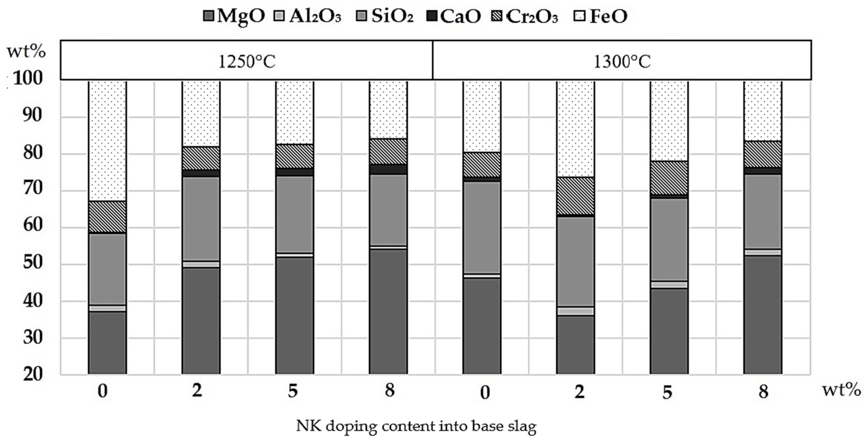
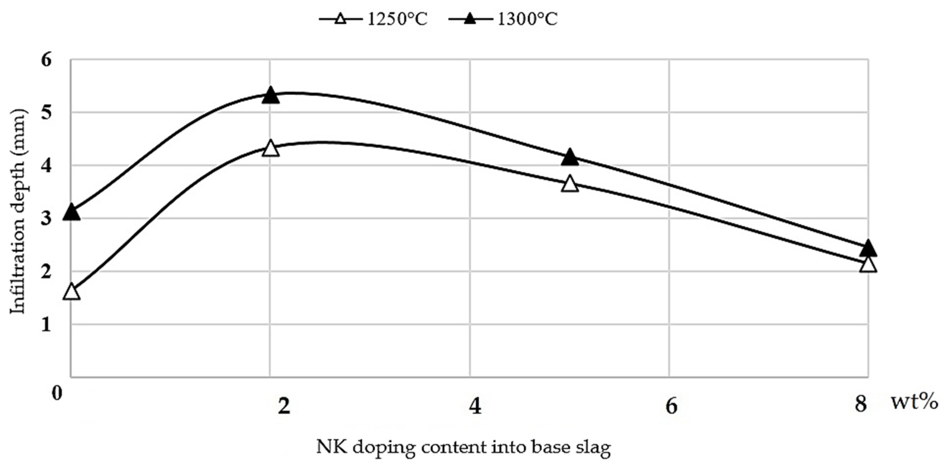
The effect of higher temperature on brick dissolution was corroborated for all the M10-doped slags; however, in the case of the NK-doped slag, it was not always higher than the fayalite-based slag for the 2 and 5 wt% dopings, as is shown in Figure 8. This was due to the concentration gradient quickly reducing inside the pores, mitigating the effect of the higher temperature and finally decreasing the dissolution rate of the brick.

4.2. Infiltration by Molten Slag

It is possible to obtain an expression for the slag infiltration rate using a dynamic force balance inside the refractory pores and considering a cylindrical control volume, where the capillary and metallostatic forces compete with the internal and viscous forces. Equation (5) represents the molten slag infiltration rate through a pore (Vp). This mainly depends on the distance from the hot face (x), the surface tension ( σ ), the pore radius (R), the pore radius variable (r), the contact angle ( θ ,) and the kinematic viscosity of the slag (μ).
V p r , x = Δ P + 2 σ Cos θ R x 8   μ x R 2     r 2 [ m / s ]
According to Equation (5), Vp decreases as the distance from the hot face increases, where the internal gas pressure increases considerably because the available space is reduced. On the other hand, if the infiltrated slag viscosity decreases inside the pore, the infiltration rate increases since both parameters are inversely proportional.
Therefore, the infiltrated slag reaches its maximum infiltration level when: (i) the pore length ends; (ii) the liquid reaches the critical solidification isotherm; (iii) the molten slag has an inertial force equal to the dynamic and capillary forces, according to its viscosity; or (iv) the infiltration rate is so low that it can be considered zero.
During the laboratory experiments, the temperature inside the refractory drill cores could be assumed to be constant because it was determined by the internal temperature of the furnace. Therefore, it was unlikely that the slag infiltrating through the core reached the critical solidification isotherm. In the case of the length of the pore and the internal pressure of the brick, they were common variables for all the experiments, and therefore, they do not represent a comparative argument on the infiltration results. Thus, the infiltration phenomenon is determined exclusively by the viscosity of the molten phase.
As was previously explained, the doped molten slag is more fluid than the fayalite-based slag due to the presence of basic oxide provided by the clay minerals. This slag infiltrates the refractory material and the dissolution from the brick begins, providing magnesium, aluminum, and chromium ions to the infiltrated molten slag phase.
The low initial viscosity accelerates the dissolution process of the brick, quickly promoting ion saturation and then, from a certain critical concentration, exponentially increases the slag viscosity [15]. This phenomenology may explain the behavior observed during the experiments, in which an increase in the content of clay minerals did not imply higher infiltration of the slag into the brick. In fact, the latter decreased for the highest clay doping levels.
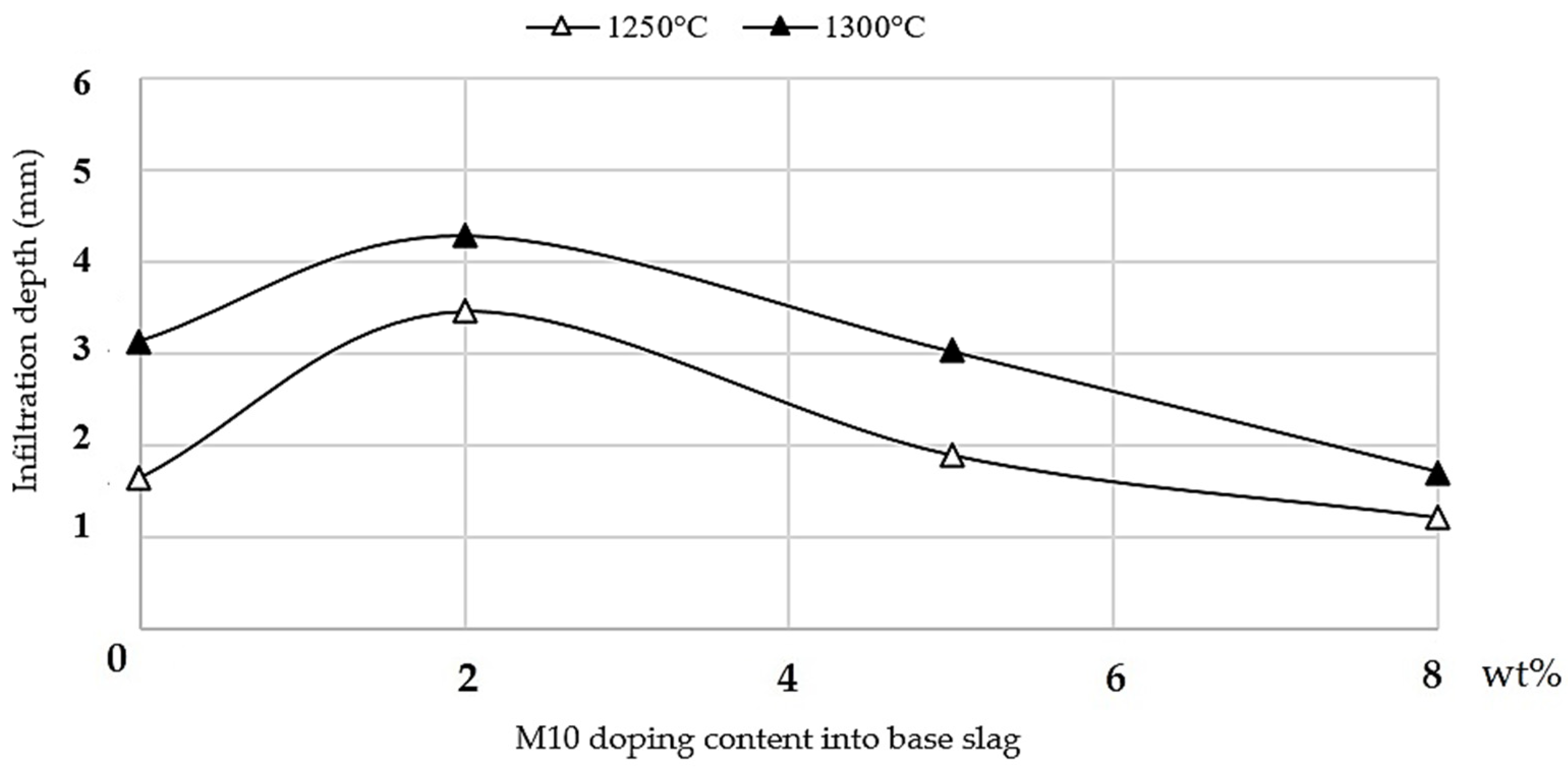
As compared with the base case, the infiltration increased with the addition of 2 wt% M10 doping due to the incorporation of basic (MgO-Al2O3) oxides into the molten phase, which decreased its viscosity, promoting fluidity. Nevertheless, with the increased presence of M10 (5 and 8 wt%) there was a faster contribution from both the basic oxides from the clay doping and (MgO) from the refractory material, which strongly increased slag viscosity, stopping infiltration faster than in the base slag. This behavior was also previously reported by Kowalczyk [15].
On the other hand, for the experiments with NK doping at 1250 °C, the infiltration level was always higher than with the fayalite-based slag due to the decrease in the viscosity. In addition, when the experimental temperature was 1300 °C, the same trend as that described for the M10-doped slag was observed. As was already established, the NK-doped slag exhibited a lower viscosity and, therefore, higher infiltration into the brick than the M10-doped slag.
The effect of temperature on the infiltration level is related to the viscosity of the molten slag phase. As can be observed in Figure 6 and Figure 9, for the M10- and NK-doped slags, respectively, higher temperatures decrease the viscosity and increase the infiltration by increasing the porosity of the refractory material.

4.3. Chemical Dissolution on the Refractory Hot Face

The dissolution process on the surface of the refractory material has one different characteristic when compared to the dissolution process in the structure inside the pores, as described in Section 4.1. On the surface, dissolution takes place in three consecutive stages:
  • The reactants are transported to the interface;
  • The reaction takes place at the interface;
  • The products are transported out of the interface.
Therefore, when the phenomenon occurs on the surface, one stage is added to the dissolution process, establishing a new kinetic parameter related to the transport of the reactants to the refractory surface. In any case, the transport of the products outside the interface represents the limiting stage for the dissolution rate. Molecular diffusion can also be represented by Fick’s first laws, see Equation (2).
According to the present experimental arrangement, the radii of the core perforations were larger than those of the refractory pores; therefore, the diffusion boundary layer on the refractory surface was thicker, decreasing the mass diffusion flux and the corresponding refractory brick wear.
Inside the core perforations, the slag exhibited natural convection movement due to the difference in its density in the bulk. This was also the case close to the refractory surface (caused by the dissolution process), which always resulted in a laminar flow. This movement establishes a velocity gradient, which ranges from a maximum in the molten slag bulk to a minimum, i.e., close to zero, caused by the adhesion condition at the refractory wall.
For the fayalite slag, the dynamic viscosity is much larger than the mass diffusivity. It was reported that the velocity boundary layer thickness is generally over 10 times that of the mass boundary layer [14], which results in an extremely slow velocity for quasi-stationary slag during natural convection and the dissolution rate of the refractory brick being controlled by molecular diffusion.
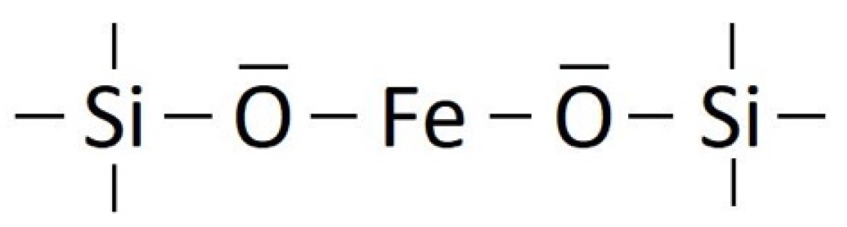
Studies exploring the behavior of the viscosity of fayalite slag in relation to the Fe/SiO2 ratio show that, for a value close to 1.5, there is a specific maximum of viscosity at 1250 °C [16]. This phenomenon is attributed to the cation bridge associated with Fe2+ and tetrahedra SiO44+, as shown in Figure 11.
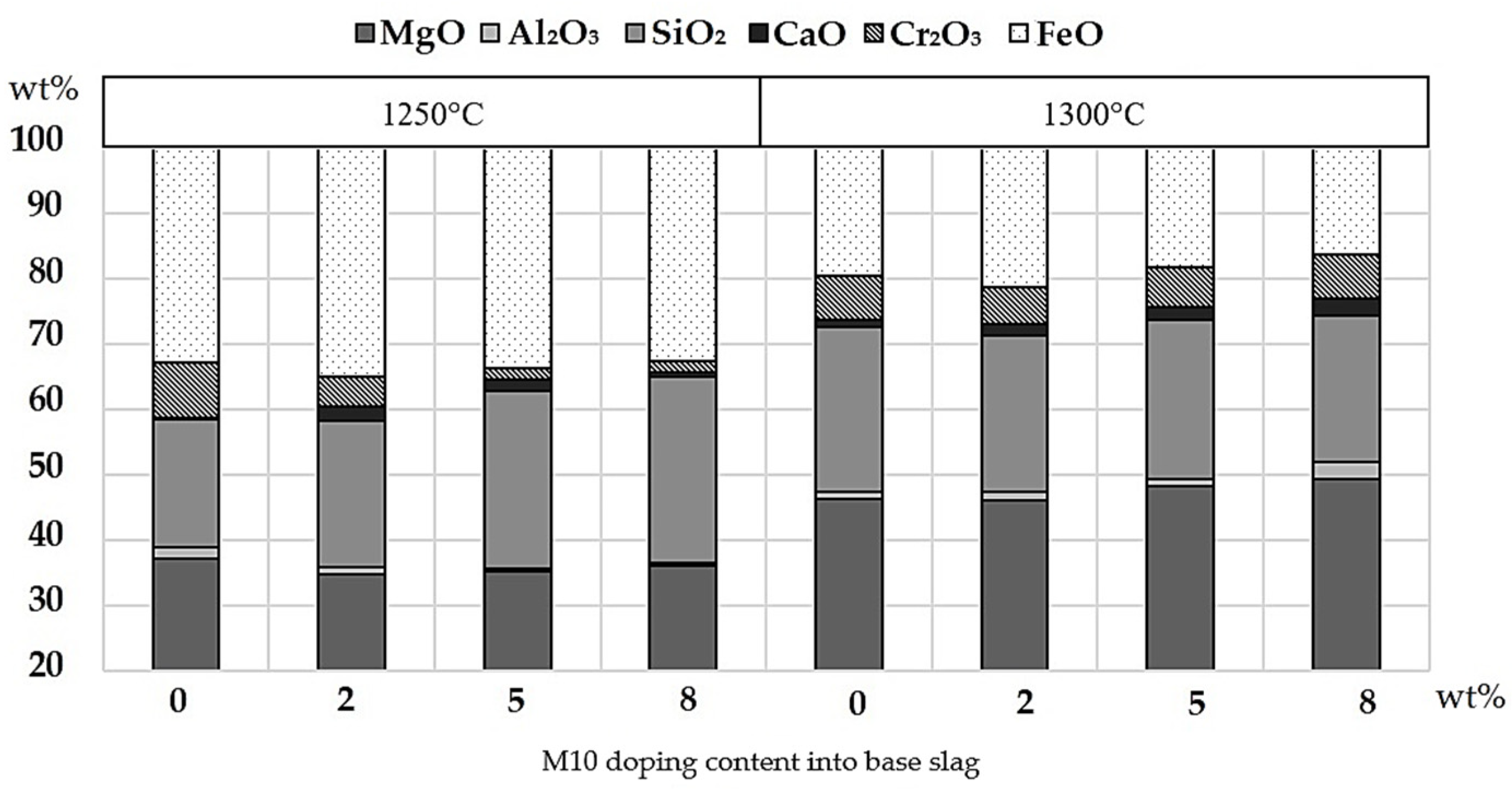
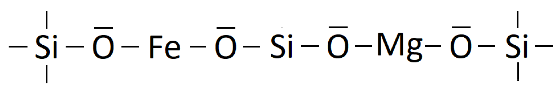
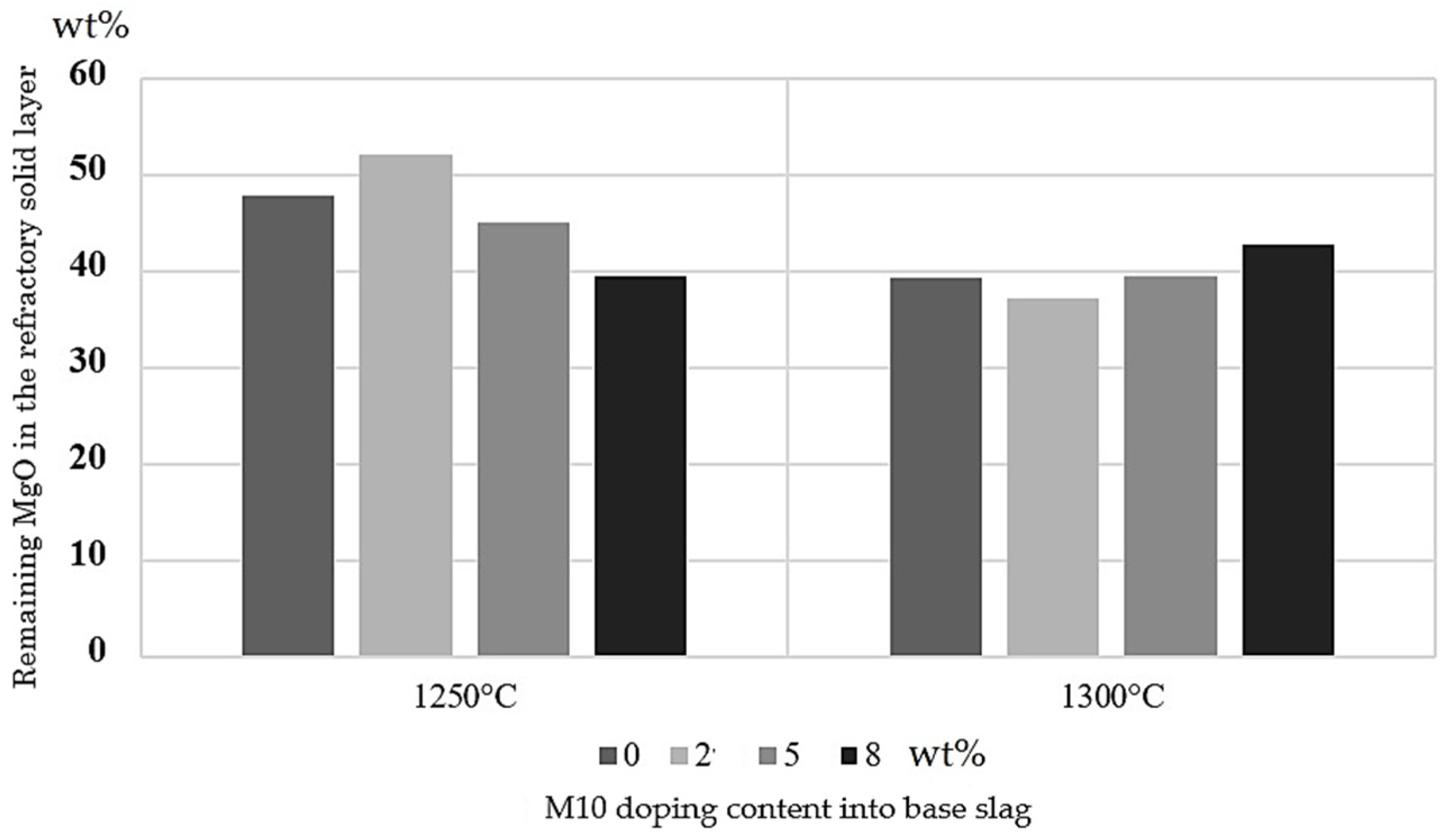
Concerning the doping effect, the presence of M10 at 1250 °C promotes the dissolution of magnesia from the refractory brick into the molten slag, but according to the results, there was an exception when the doping content was 2 wt%. This may be attributed to the Mg+2 contribution from the doping, which promotes the formation of a polymerized slag structure (Figure 12), increasing its viscosity and peaking and delaying the dissolution of the refractory brick, as shown in Figure 7.
When the M10 doping content was 5 and 8 wt%, the cation effect disappeared due to the increase in the interionic forces present in the molten slag. From this point, at 1250 °C, the dissolution of the refractory brick was promoted by the presence of the M10.
Regarding the effect of a higher temperature, it is important to recognize that the polymerized slag structure is easily destroyed at 1300 °C because the ions acquire more energy [16], justifying the behaviors obtained in this study, as shown in Figure 7.
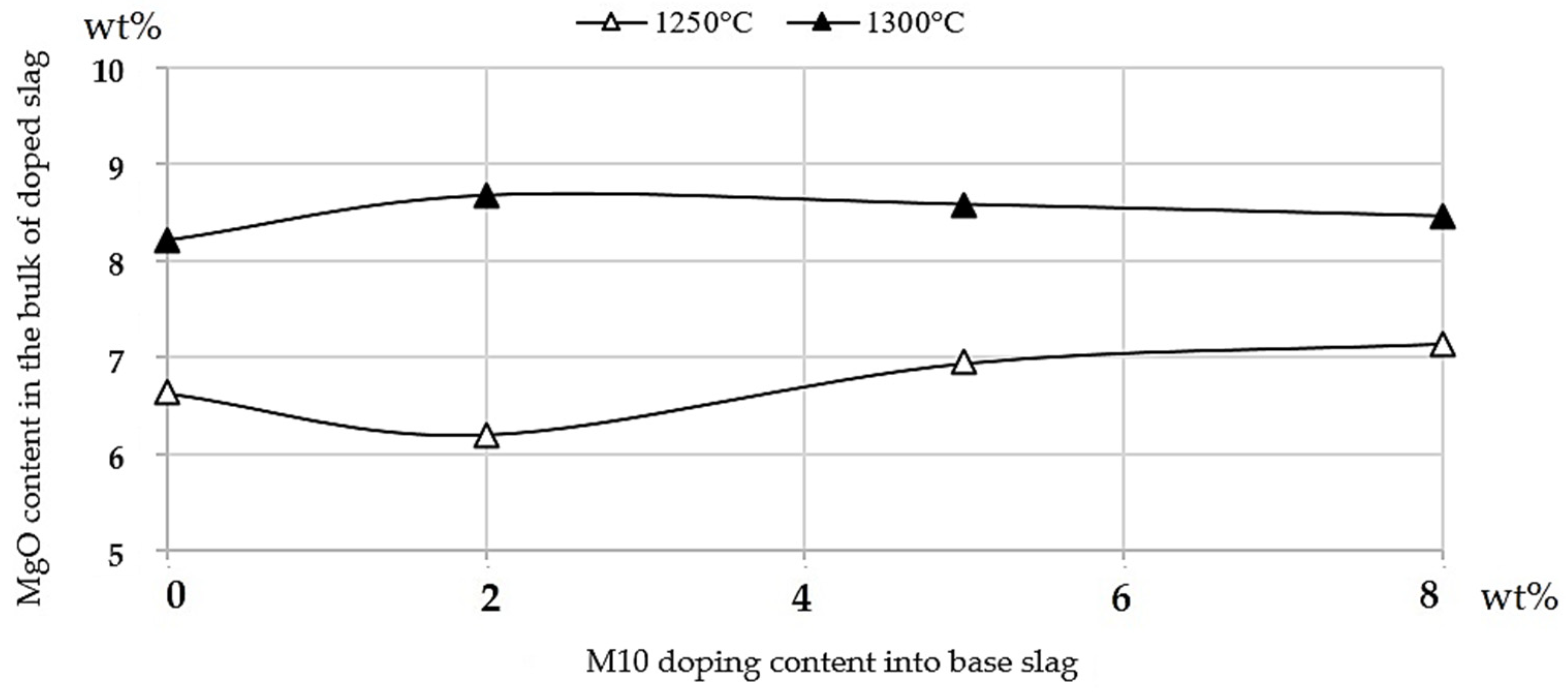
Figure 13 shows the remaining MgO content in the SLR on the refractory hot face that was present as the magnesium spinel was formed by the interaction between the brick surface and the M10-doped slag. The dissolution behavior of the magnesia from the brick, previously described and shown in Figure 7, is consistent with its remnants observed in the solid hot face of the refractory brick. When the dissolution of the brick increases, the remaining MgO in the hot face decreases.
At 1300 °C, the lower initial viscosity of the molten slag promoted by the basic oxide from the M10 doping and the higher temperature accelerated the refractory dissolution, as compared with the case at 1250 °C, but only in the infiltrated slag in contact with the hot face of the brick (in a steady-state condition). This decreased the magnesia concentration gradient generated between that zone and the molten slag phase near the interface.
Finally, it was observed that the dissolution of MgO from the refractory material into the molten-doped slag decreased as the M10 doping content increased, but the concentration of magnesia was always higher as compared with the base case. This behavior is consistent with the increasing quantities of magnesia that remained in the SLR, as shown in Figure 13.
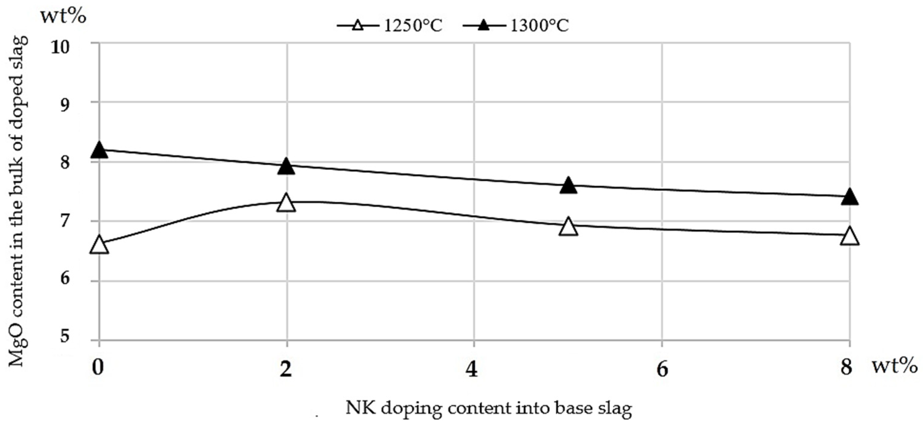
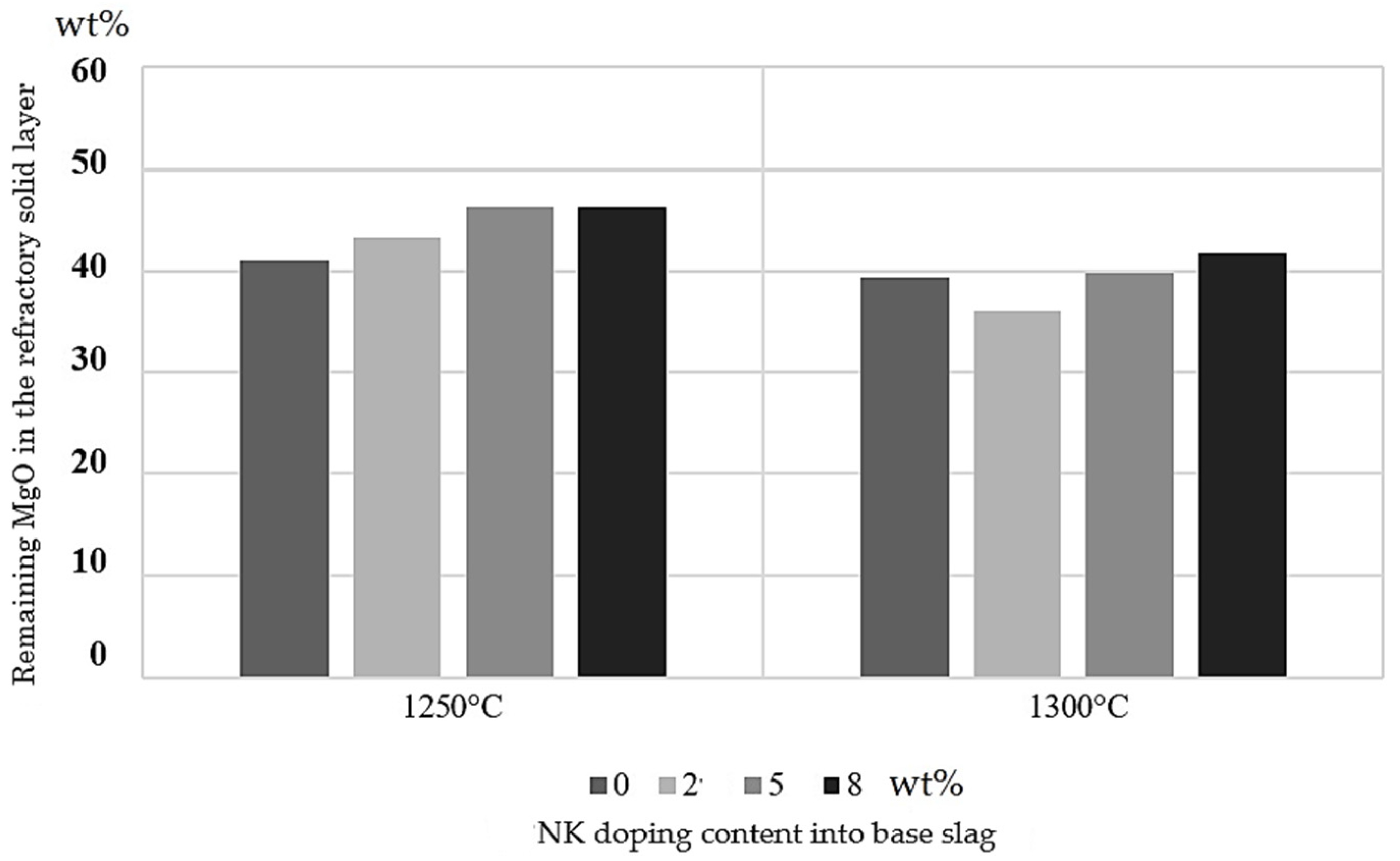
For the NK doping, as the NK doping increased the dissolution of magnesia from the refractory hot face into the doped slag decreased for both experimental temperatures. Although the trends are similar, the refractory dissolution was stronger at 1300 °C because the viscosity decreased and both the solubility and the liquid area of the slag increased, as was expected.
According to Figure 14, it is possible to observe that, at 1250 °C, the highest dissolution was seen for the fayalite-based slag; however, in contrast to Figure 10, this case was observed to have the lowest content of magnesia in the bulk at the end of the experiment. This may be explained because, for a steady-state condition, the molten slag is not fluid enough, and the MgO remains close to the refractory face and does not diffuse into the bulk. The reaction mainly occurs close to the boundary layer, as can be corroborated by Figure 9, which shows the lowest level of infiltration.
It is important to note that, for the same amount of doping, the NK-doped slag exhibited almost double the Al2O3 content as compared with the M10-doped slag. For this reason, at 2 wt% of the MK doping, the larger amount of aluminum ions reduced the magnetite in the slag, decreasing viscosity, promoting infiltration, and allowing the magnesia from the refractory material to quickly move to the bulk of the slag through a more fluid molten phase. For higher levels of doping, aluminum spinels appeared, increasing viscosity and slowing down MgO dissolution.
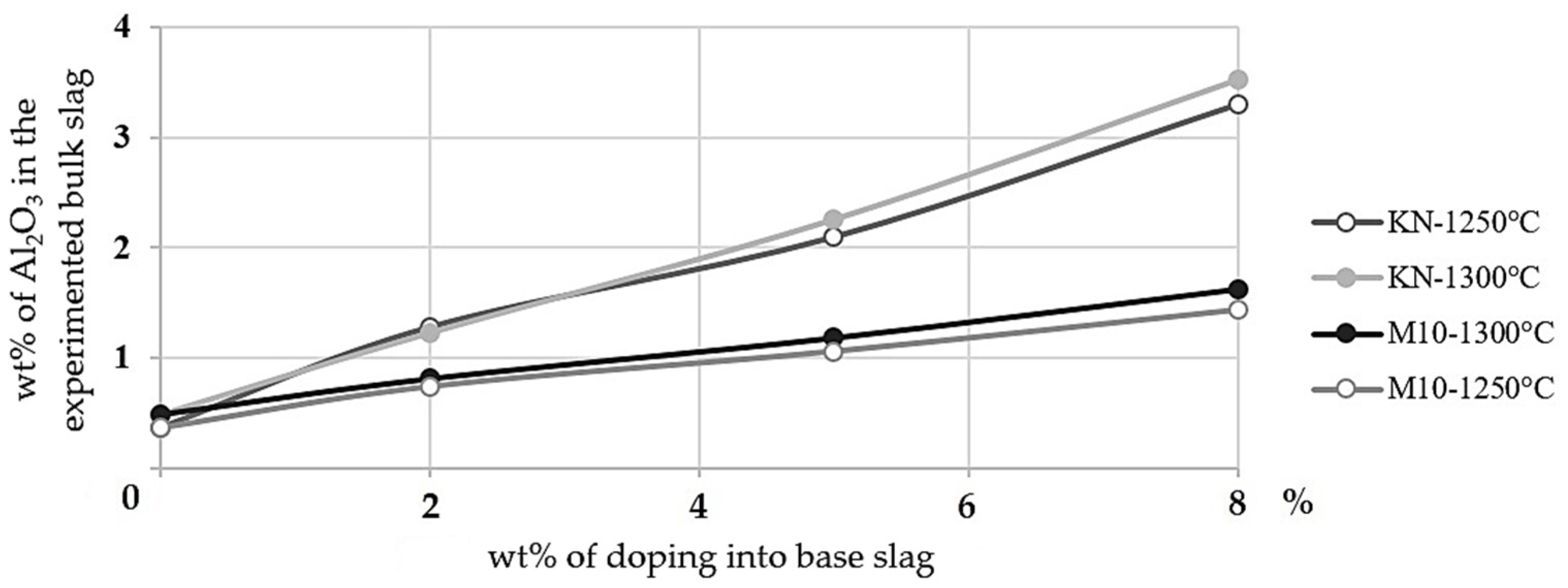
Finally, Figure 15 shows the content of alumina in the slag as a function of the doping addition to the system at 1250 and 1300 °C. It can be clearly observed that, given the corresponding clay mineral doping composition, the NK-doped slag progressively increased the Al2O3 in the bulk slag as compared to the M10-doped slag and that the content was even larger at 1300 °C because the saturation shifted as the solubility increased at a higher temperature.

5. Conclusions

In this study, the effect of the presence of clay minerals on the structure of fayalite slag and refractory brick wear was investigated at 1250 and 1300 °C through static tests using industrial refractory bricks as crucibles. We analyzed the representative samples using the SEM-EDS, XRD, and ICP-OES techniques.
Kaolinite and montmorillonite were used as clay minerals because, due to their planar structure, they are the most frequently incorporated into copper sulfide concentrates during the froth flotation process, with detrimental effects in copper smelters, mainly affecting the slag properties and the subsequent operational results. Nowadays, there is no clear strategy with which to address their presence in this context. Thus, it is important to identify them and attempt to control their concentration in the feed. In this sense, the study demonstrated a geometallurgical relationship between the presence of clay minerals in the feed and the wearing phenomenon of the refractory bricks during the smelting stage.
The wearing mechanism was discussed in relation to interactions with the slag on its hot surface boundary layer and inside because of infiltration. For all cases, the infiltration depth into the brick and the structure of the refractory material and slag phase were investigated and compared with the fayalite slag base case and in relation to the initial type and content of the clay minerals.
It was determined that the clay minerals have different effects on the refractory lining according to their chemical compositions and crystalline structures. The capacity of the slag to infiltrate into the refractory material was inversely proportional to the initial content of the clay minerals. This was due to the contribution of the basic oxides, which decreased the viscosity of the experimented slag until it reached saturation. In comparison to the fayalite-based slag, the clay mineral-doped slag caused a higher dissolution of the refractory brick. In addition, the kaolinite produced a stronger effect on refractory wearing due to the higher content of alumina as compared to the montmorillonite. Some exceptions were observed and are discussed in relation to the viscosity, solubility, ion exchange, and the formation of new compounds in the system. Finally, from our study, it was concluded that the increase in temperature from 1250 to 1300 °C not only increased the solubility and decreased the viscosity of the slag phase, it also intrinsically increased diffusivity during mass transfer, which promoted infiltration and the dissolution rate of the refractory brick.
Variations in the concentrated chemical composition and temperature generate uncertainty in the copper production process. Moreover, the type of gangue generates different effects on the refractory lining as was confirmed in this study. The results herein represent the first step in understanding the geometallurgical interactions at play in this operation.

Author Contributions

Conceptualization, J.O. and L.V.; formal analysis, J.O. and C.P.; funding acquisition, L.V.; investigation, J.O. and C.P.; methodology, J.O. and C.P.; supervision, L.V.; writing—original draft, J.O. and L.V.; writing—review and editing, J.O. and L.V. All authors have read and agreed to the published version of the manuscript.

Funding

This research was funded by: (1) ANID through the project BASAL-AFB180004 and (2) CORFO through the project INNOVA CSIRO—CHILE 10CEII-9007. The authors acknowledge the Advanced Mineral Technology Center at the University of Chile and CSIRO Chile for their support in this work by providing equipment and facilities.

Data Availability Statement

Not applicable.

Conflicts of Interest

The authors declare no conflict of interest.

References

  1. Malfliet, A.; Lotfian, S.; Scheunis, L.; Petkov, V.; Pandelaers, L.; Jones, P.; Blanpain, B. Degradation mechanisms and use of refractory linings in copper production processes: A critical review. J. Eur. Ceram. Soc. 2013, 34, 849–876. [Google Scholar] [CrossRef]
  2. Ndlovu, B.; Farrokhpay, S.; Bradshaw, D. The effect of phyllosilicate minerals on mineral processing industry. Int. J. Miner. Process. 2013, 125, 149–156. [Google Scholar] [CrossRef]
  3. Berger, B.R.; Ayuso, R.A.; Wynn, J.C.; Seal, R.R. Preliminary Model of Porphyry Copper Deposits; USGS Numbered Series 2008-1321; U.S. Geological Survey: Reston, VA, USA, 2008. Available online: http://pubs.er.usgs.gov/publication/ofr20081321 (accessed on 29 June 2022).
  4. Chen, X.; Peng, Y. Managing clay minerals in froth flotation—A critical review. Miner. Process. Extr. Met. Rev. 2018, 39, 289–307. [Google Scholar] [CrossRef] [Green Version]
  5. Petkov, V.; Jones, P.; Boydens, E.; Blanpain, B.; Wollants, P. Chemical corrosion mechanisms of magnesia–chromite and chrome-free refractory bricks by copper metal and anode slag. J. Eur. Ceram. Soc. 2007, 27, 2433–2444. [Google Scholar] [CrossRef]
  6. Barthel, H. Wear of chrome magnesite bricks in copper smelting furnaces. Interceram 1981, 30, 250–255. [Google Scholar]
  7. Fahey, N.P. Refractory Wear by Calcium Ferrite Slag in Continuous Copper Converting. Ph.D. Thesis, RMIT University, Melbourne, Australia, 2002. [Google Scholar]
  8. Parra, R.; Verdeja, L.F.; Barbés, M.F.; Goñi, C.; Bazán, V. Analyzing furnace-lining integrity using nodal wear modeling. JOM 2005, 57, 29–36. [Google Scholar] [CrossRef]
  9. Kacke, O.N.; Kubaschewski, O.; Hesselmann, Y.K. Thermochemical Properties of Inorganic Substances: Supplement, 2nd ed.; Springer Science & Business Media: New York, NY, USA, 1991. [Google Scholar]
  10. Brigatti, M.F.; Galan, E.; Theng, B. Chapter 2 Structures and Mineralogy of Clay Minerals. In Developments in Clay Science; Brigattia, M.F., Galanb, E., Theng, B.K.G., Eds.; Elsevier: Amsterdam, The Netherlands, 2006; Volume 1, pp. 19–86. Available online: http://www.sciencedirect.com/science/article/pii/S1572435205010020 (accessed on 21 November 2016).
  11. Zhao, B.; Jak, E.; Hayes, P.C. The effect of Al2O3 on liquidus temperatures of fayalite slags. Met. Mater. Trans. A 1999, 30, 597–605. [Google Scholar] [CrossRef]
  12. Zhao, B.; Jak, E.; Hayes, P.C. The effect of MgO on liquidus temperatures of fayalite slags. Met. Mater. Trans. A 1999, 30, 1017–1026. [Google Scholar] [CrossRef]
  13. Goñi, C. Desarrollo y Aplicación de Modelos de Corrosión Refractaria Para un Convertidor Peirce—Smith. Ph.D. Thesis, Universidad de Concepción, Concepción, Chile, 2004. [Google Scholar]
  14. De Aza, A.H. Corrosión de materiales refractarios por escorias y vidrios fundidos. Boletín Soc. Española Cerámica Vidr. 1996, 35, 87–101. [Google Scholar]
  15. Kowalczyk, J.; Mroz, W.; Warczok, A.; Utigard, T.A. Viscosity of copper slags from chalcocite concentrate smelting. Met. Mater. Trans. A 1995, 26, 1217–1223. [Google Scholar] [CrossRef]
  16. Kucharski, M.; Stubina, N.M.; Toguri, J.M. Viscosity Measurements of Molten Fe–O–SiO2, Fe–O–CaO–SiO2, and Fe–O–MgO–SiO2Slags. Can. Met. Q. 1989, 28, 7–11. [Google Scholar] [CrossRef]
Figure 1. (a) Magnesia chromite drill core obtained from industrial refractory brick; (b) drill core perforations filled with a mixture of synthetic fayalite slag doped with clay minerals.
Minerals 12 01431 g001
Figure 2. (a) Schematic arrangement for the corrosion static experiment; (b) magnesia chromite drill core cut and polished for characterization and analysis in the selected analysis area for the refractory hot face and the slag bulk.
Minerals 12 01431 g002
Figure 3. The presence of periclase grain (P), primary chromite (P-chr), a secondary chromite phase (S-chr), and a matrix phase (M) in the raw refractory brick determined by backscattered electrons (BSE) in SEM imaging.
Minerals 12 01431 g003
Figure 4. BSE image in SEM: (a) phases present in the final bulk slag; (b) phases present in the refractory brick hot face.
Minerals 12 01431 g004
Figure 5. Infiltrated slag composition determined by SEM-EDS v/s montmorillonite K10 (M10) doping into base slag at 1250 and 1300 °C.
Minerals 12 01431 g005
Figure 6. Infiltration depth of M10-doped slag into the refractory v/s the doping content at 1250 and 1300 °C.
Minerals 12 01431 g006
Figure 7. Magnesia content in the bulk of the doped slag v/s the initial M10 doping content, measured by XRD-WPPF.
Minerals 12 01431 g007
Figure 8. Infiltrated slag composition determined by SEM-EDS v/s NK doping into the base slag at 1250 and 1300 °C.
Minerals 12 01431 g008
Figure 9. Infiltration depth of NK-doped slag into the refractory material v/s the doping content at 1250 and 1300 °C.
Minerals 12 01431 g009
Figure 10. Magnesia content in the bulk of the doped slag v/s the initial natural kaolinite (NK) doping content, measured by XRD-WPPF.
Minerals 12 01431 g010
Figure 11. Cation bridge of Fe2+ and tetrahedra SiO44+ in fayalite slag [16].
Minerals 12 01431 g011
Figure 12. Cation bridge of Fe2+, Mg2+, and tetrahedra SiO44+ in fayalite slag.
Minerals 12 01431 g012
Figure 13. Magnesia content in the solid layer remainder (SLR) on the hot face of the refractory material in contact with M10-doped molten slag at 1250 and 1300 °C, measured by SEM-EDS.
Minerals 12 01431 g013
Figure 14. Magnesia content in the SLR on the hot face of the refractory in contact with NK-doped molten slag at 1250 and 1300 °C, measured by SEM-EDS.
Minerals 12 01431 g014
Figure 15. Alumina content in the bulk slag measured by ICP-OES v/s doping content at 1250 and 1300 °C.
Minerals 12 01431 g015
Table 1. Elemental composition in wt% of the natural kaolinite and montmorillonite K10—Sigma Aldrich.
CodeClay MineralsSourceAlSiMgFeKOther
M10Montmorillonite K10Supplier7.7031.31.102.00-57.8
ICP-OES6.4030.51.001.700.2059.4
NKNatural KaoliniteSupplier19.820.4-0.301.5058.0
ICP-OES17.419.9-0.201.3061.1
Table 2. Calculated compositions of the doped slags loaded for the main experiments.
Clay Mineral-Doped Slagwt% ClayFeSiAlMgFe/SiO2
Base slag + M100 *51.2015.90--1.503
251.0615.820.150.0221.507
550.5415.670.380.0551.505
849.9615.480.610.0881.506
Base slag + NK0 *51.2015.90--1.503
250.5715.820.42-1.492
550.1615.531.06-1.508
849.0415.261.69-1.500
* Considered as the base case.
Table 3. Composition of the selected refractory brick according to the supplier datasheets.
[wt%]MgOCr2O3Al2O3Fe2O3FeOSiO2Total
Refractory Brick63.519.55.20.908.12.8100
Table 4. Definition of relevant terms.
ConceptDefinition
DiffusionMovement of individual molecules of a substance through a semipermeable barrier from an area of higher concentration to an area of lower concentration.
InfiltrationMolten slag entering the refractory structure promoted by the forces or gradients present in the system.
DissolutionProcess in which a solute in a solid phase (refractory) dissolves in a solvent to form a solution (molten slag).
ReactionChemical process in which substances are changed into different substances after acting mutually on each other.
Publisher’s Note: MDPI stays neutral with regard to jurisdictional claims in published maps and institutional affiliations.

