1. Introduction
The sandy braided river is an important type of terrestrial sedimentary system. It is still difficult to establish a highly reliable 3D geological model of the braided river reservoir [
1], due to the strong heterogeneity of its reservoir [
2], frequent river migration and oscillation, complex spatial stacking pattern, and distribution pattern. Analysis of architecture elements is a significant research method for reservoir characterization and a hot topic of current research; many researchers have conducted more in-depth studies on braided river reservoir architecture [
3,
4,
5,
6,
7,
8,
9,
10,
11,
12], while a lot of attention has been focused on modeling braided river reservoirs [
13,
14,
15,
16].
Previous research has examined the internal architecture distribution characteristics and quantitative size of the reservoir using techniques such as subsurface reservoir well-to-well comparisons, field outcrops, and sedimentation simulation trials [
17,
18,
19]. At the same time, a 3D geological model was established using the braided river’s sedimentation as a guide [
2,
20]. Multiple-level constraints, hierarchical facies control, hierarchical modeling, multiple-step modeling, and embedded modeling are some methods used to simulate braided river reservoirs [
13,
21,
22,
23]. Currently, sequential indication simulation [
24,
25,
26], object-based simulation [
15,
27,
28], human–computer interactive modeling [
9,
29], and multiple-point geostatistical modeling methods [
13,
30] are the principal methods utilized in braided river reservoir modeling. Previous research on braided river reservoir architecture classification and modeling methods has offered some guidance and ideas for the establishment of a sedimentary microfacies model for the Daniudi gas field.
Xun [
31] utilized the sand body spreading map as a constraint to establish a geological model of the D66 well region in the Daniudi gas field, using a deterministic modeling method. Li et al. [
32] used the Sequential Indication Simulation method to establish the facies model of the H1 member of the Daniudi gas field under the constraint of sedimentary microfacies diagram. Previous methods of reservoir modeling in the Daniudi gas field have mostly used traditional deterministic modeling or stochastic modeling methods based on two points. Although there have been architectural anatomical studies for the area, there are fewer studies for multiple-point geostatistical modeling based on different levels of architecture units.
In this paper, based on the braided river sedimentary system developed in the Lower Shihezi Formation of the Daniudi gas field in the Ordos Basin, and taking the H1 member as an example, we finely dissected the 5–3 level architecture units in the study area based on the combination of hierarchical, level-by-level embedding and progressive modeling, as well as integrated logging data and core analysis to classify three sets of condition data corresponding to the type and number of architecture units. The hierarchical geological model was established using a mix of qualitative architecture anatomy and quantitative pre-architecture scale. The spreading of braided river, channel bar, braided channel, and interlayer in the target formation in the study area is predicted, which is significant for guiding the efficient development of the remaining gas in the braided river reservoir in Daniudi.
2. Geological Setting
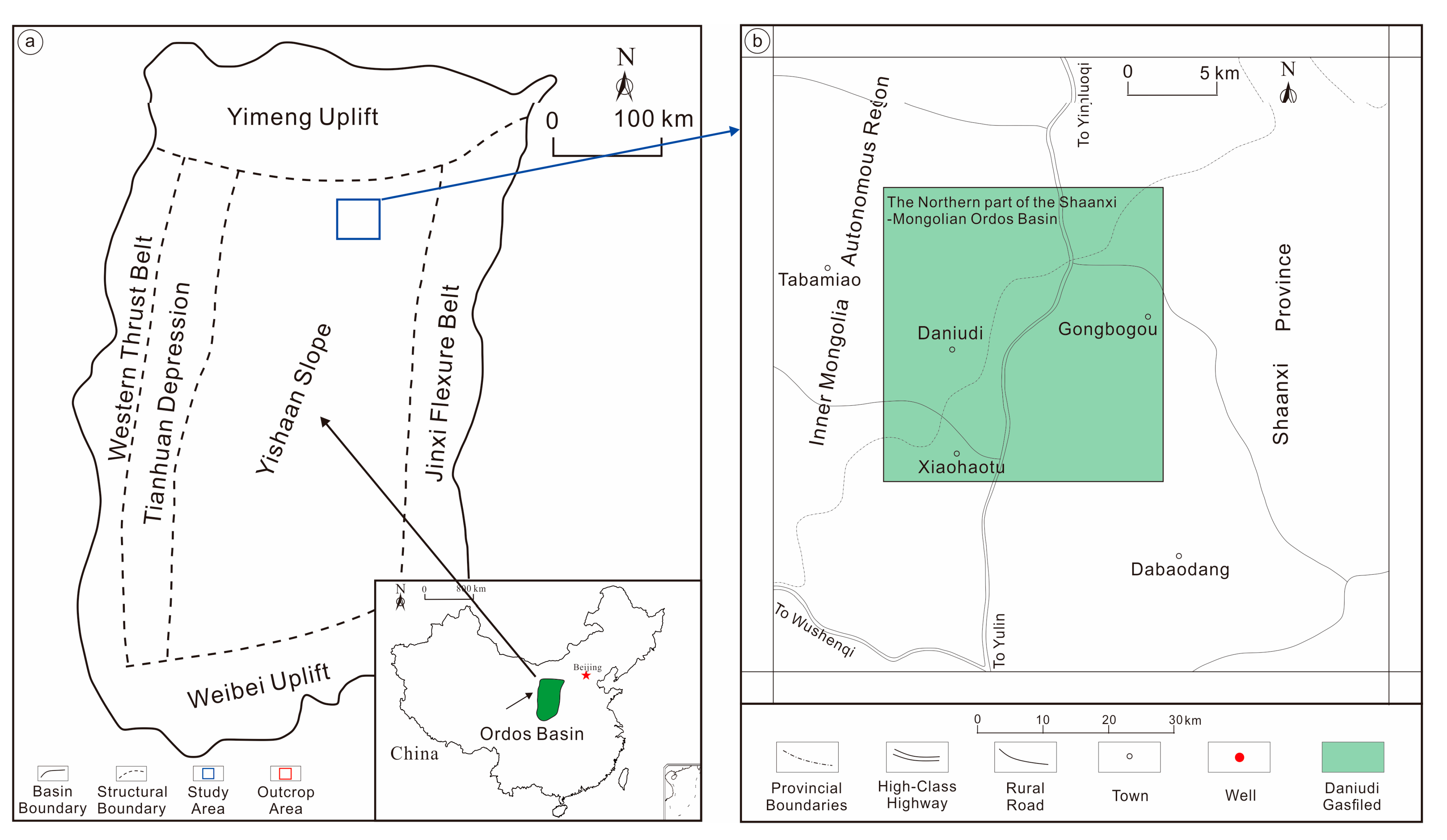
The Ordos Basin is located in northern China (
Figure 1a) and is the second-largest sedimentary basin in China. It is split into six primary tectonic units, including the Yimeng Uplift in the north, the Weibei Uplift in the south, the Western Thrust Belt and the Tianhuan Depression in the west, the Jinxi Flexural Belt in the east, and the Yishaan Slope in the center. The regional tectonics of the Daniudi gas field in the study area are located in the north-eastern part of the YiShaan slope, a secondary tectonic unit of the basin [
33] (
Figure 1b).
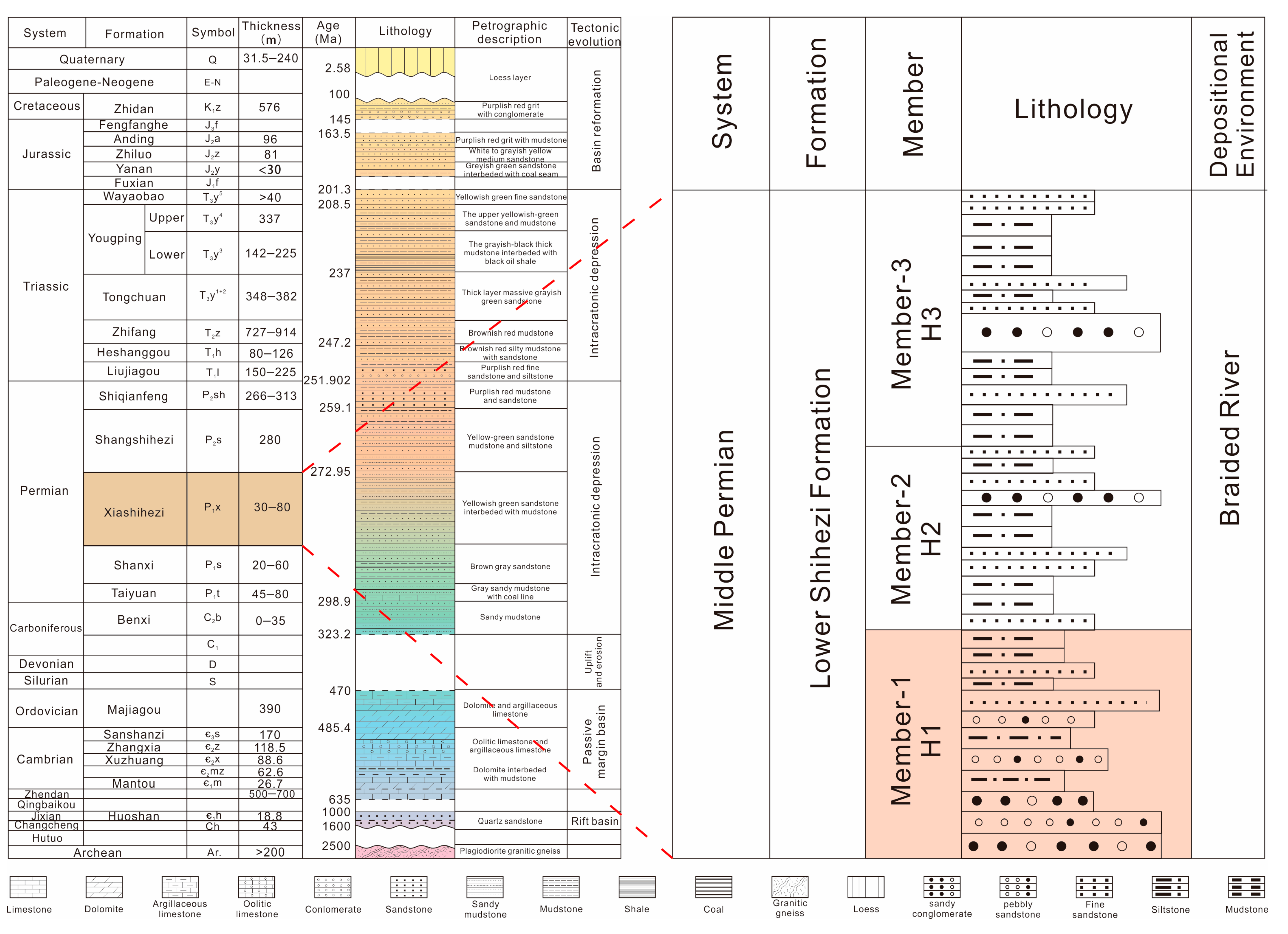
The Permian Lower Shihezi Formation is the primary gas-bearing section, which is classified into three sections from bottom to top: H1 (P1x1), H2 (P1x2), and H3 (P1x3) [
34,
35]. The Lower Shihezi Formation’s H1 sub-layer, which is finely divided into the three sub-layers, H1-1, H1-2, and H1-3, is the subject of the current study (
Figure 2). The target layer has undeveloped fractures and gentle tectonics, which is generally a gentle monocline with high northeast and low southwest [
18,
36]. Local development of a nose uplift with a near east–west trend does not constitute a larger tectonic enclosure. The Shihezi Formation of the Daniudi gas field is braided river deposits with floodplain and braided river subfacies. In the braided river system, the braided channel subfacies are the primary facies of sandstone deposition, with two microfacies evolved, namely the channel bar and the braided channel between the channel bar. The lithology is mainly light gray, gray-white glutenite, gravelly coarse sandstone, and medium-coarse sandstone interbedded with gray mudstone, with an overall thickness of 99–173 m and an average thickness of 139 m. The burial depth is 2540–2840 m.
3. Databases and Methods
This study focuses on the He-1 member of the Shihezi Formation in the Daniudi gas field, which is one of the most gas-rich areas. Currently, approximately 296 wells have been drilled, covering an area of about 188 km2, obtaining the data related to exploration and production, such as core data, logging curve data, mud logging data, seismic, and sand interpretation data, and other types of data.
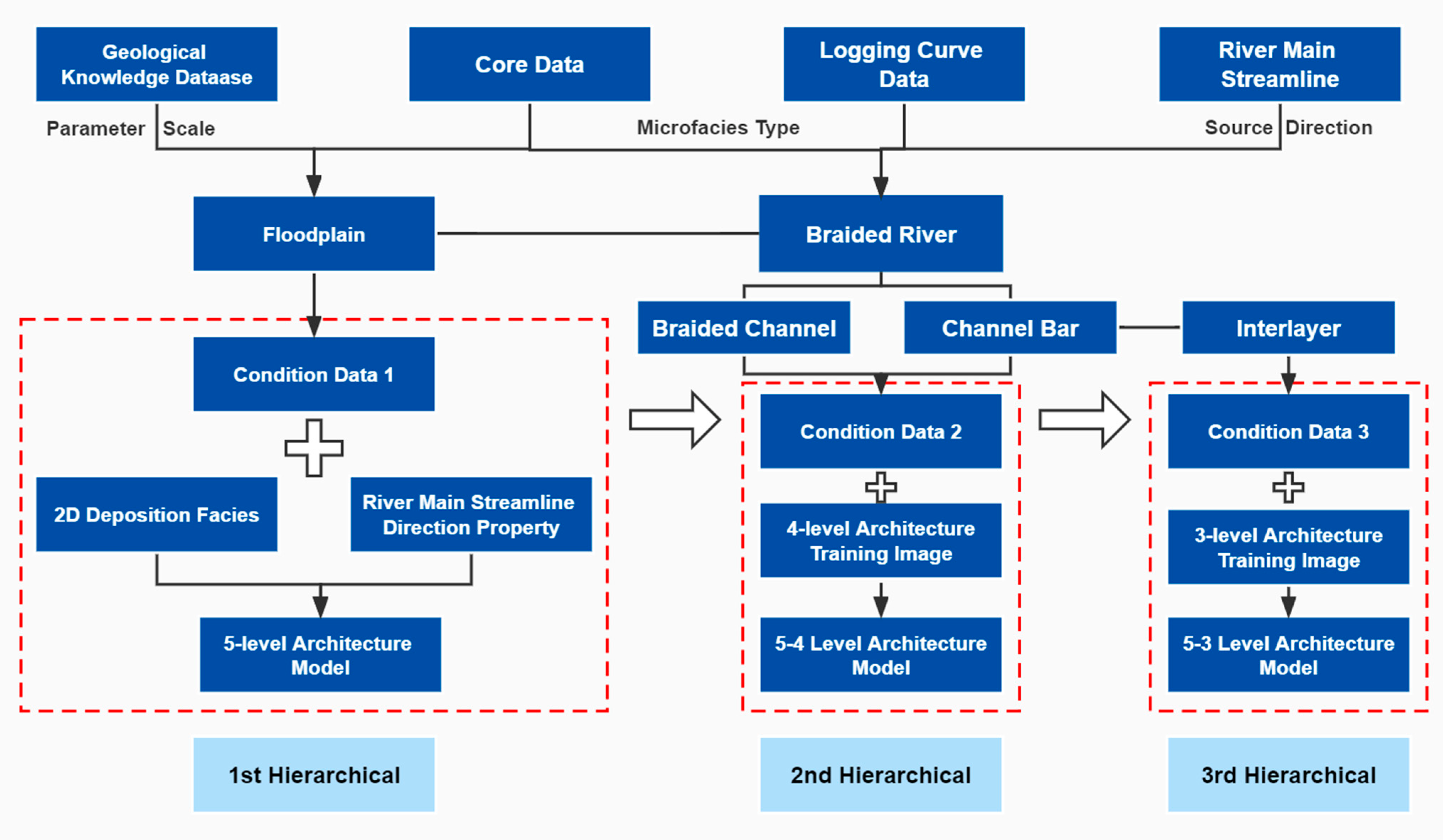
The core of the hierarchical multiple-point geostatistical modeling method proposed in this paper (
Figure 3) is based on the division of sub-architecture units at various levels of the braided river reservoir, which is combined with logging curve data and core analysis to divide the condition data into three sets corresponding to different levels of sub-architecture units. The hierarchical modeling thought is adopted to combine deterministic and object-based methods and is used step by step to establish the training images (TI) of different levels of architecture units. Furthermore, the SINSIM algorithm in multiple-point geostatistical is applied to establish the architecture model of the study area based on the corresponding level of condition data. Firstly, as the first hierarchy, we combined the architecture scale obtained from the geological knowledge database of the braided river reservoir in H1 of the Daniudi with the 5-level architecture unit (floodplain and Braided River belt) in condition data 1. The 5-level architecture model of the first hierarchy was established based on the 2D sedimentary facies figure and used the main streamline of the river to constrain the direction of the material source. Secondly, as the second hierarchy, the 5-level architecture unit (floodplain) and 4-level architecture unit (channel bar and braided channel) in condition 2 were used. The channel bar and braided channel were carved inside the braided river belt of the first hierarchy architecture model to establish the 5–4 level architecture model of the second hierarchy. Finally, as the third hierarchy, the 5-level architecture unit (floodplain), 4-level architecture unit (braided channel and channel bar), and 3-level architecture unit (interlayer) from condition data 3 were used. The interlayer was quantitatively and randomly inserted within the channel bar of the second hierarchy architecture model to create the 5-3 level architecture model of the third hierarchy. The object-based method is used in the second and third hierarchies to establish the 3D training image based on the scale of the braided channel and channel bar obtained from the geological knowledge database of the braided river reservoir in H1 of the Daniudi. Additionally, the architectural model is made using the SINSIM algorithm in multiple-point geostatistical, together with the associated condition data.
The grid of the research area is divided into 25 m × 25 m in the plane and 0.5 m in the vertical direction, with a total of 34,836,840 grids.
4. Division and Characteristics of Different Levels of Architecture Unit
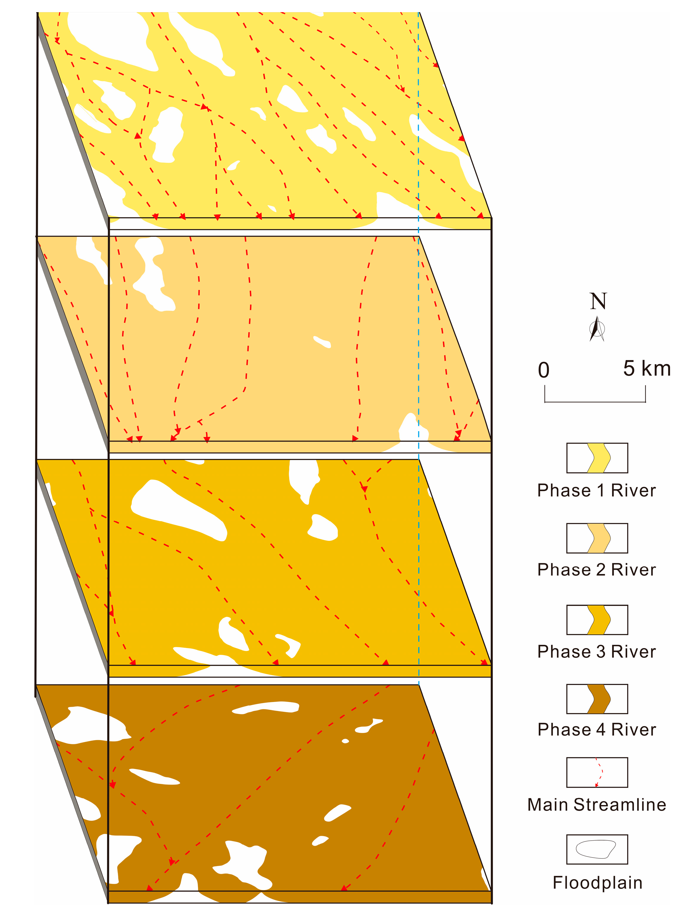
The H1 of the Lower Shihezi Formation in the research area is a shallow-water sandy braided river depositional system with multiple braided channels, small scale, rapid changes, and frequent channel bar cutting. The overall sand body in H1 member is widely dispersed, with a major channel spreading from north to south and multiple branch channels feeding into it, as well as an overall change pattern typified by a thick center and thin north–south change. The concept of architecture was originally proposed by the American sedimentologist Miall (1985) [
39]. On the basis of Miall’s architecture theory of fluvial reservoirs, Wu et al. (2010) further investigated the architecture interface delineation and architecture elements of terrestrial sedimentary reservoirs by combining the subsurface sedimentary characteristics, and they delineated a 6–0 level architecture interface [
40]. In this study, the architecture delineation scheme from Wu (2010) was used. This research focuses on characterizing the 5–3 level architecture units, namely the architecture interface between the braided river belt and the floodplain, the architecture interface between the braided channel and the channel bar, and the architecture interface of the interlayer of the channel bar (
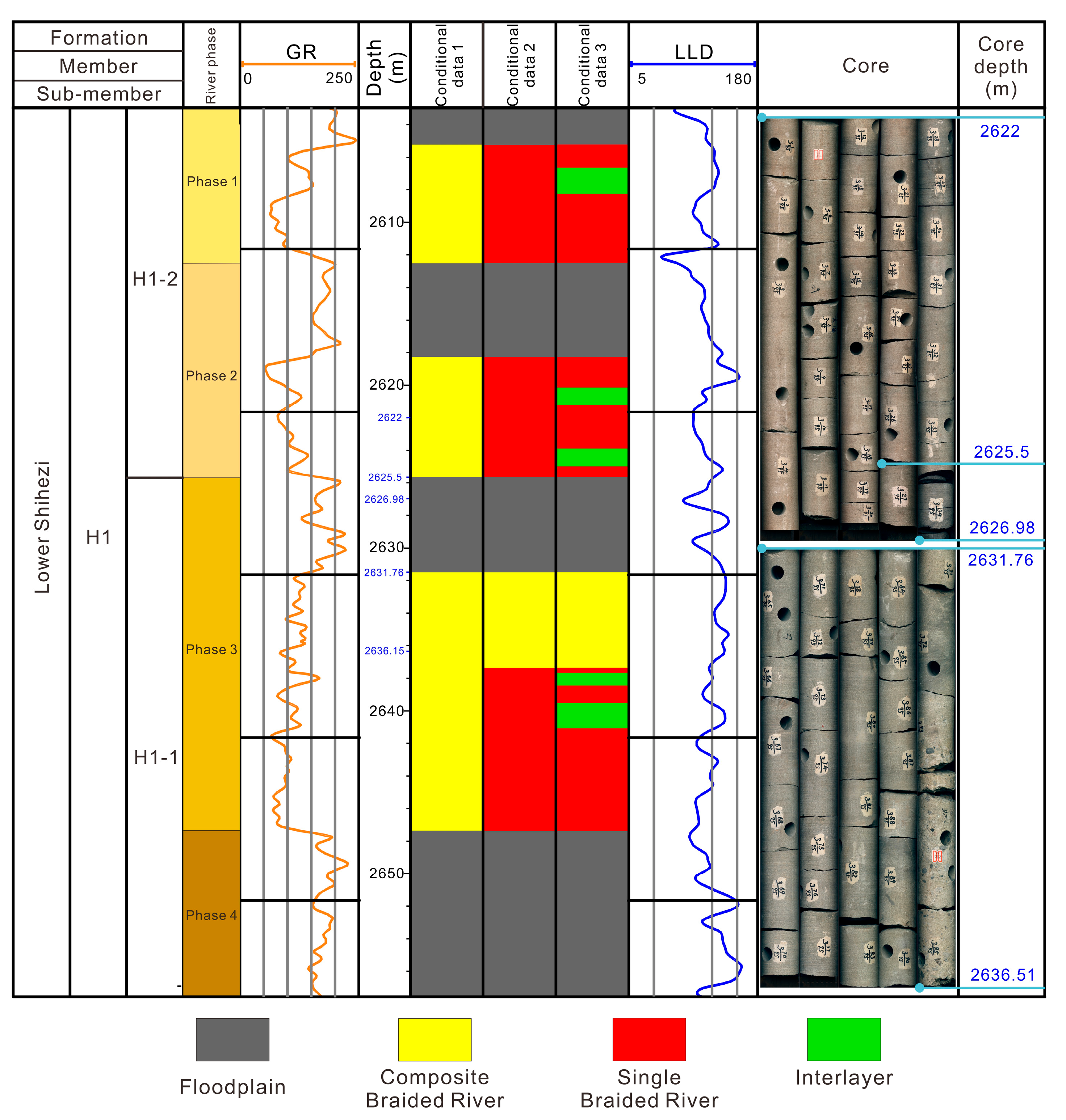
Table 1). There are two different types of 3-level architecture units: interlayer and accretion body, within the channel bar. Within a single channel bar, 2–3 interlayers develop, splitting the channel bar into 3–4 stages of accretion body. The goal of this study is to characterize how the interlayers spread and grow inside a single channel. So, the accretionary bodies will not be shown individually in this study in order to characterize the spreading and superimposition patterns of the channel bars. The upper H1-3 is a floodplain deposit; hence, it will not be further discussed. The lower H1-2 and H1-1 sub-member can be divided into four superimposed braided river deposits (
Figure 4).
4.1. 5-Level Architecture Unit
4.1.1. Braided River Belt
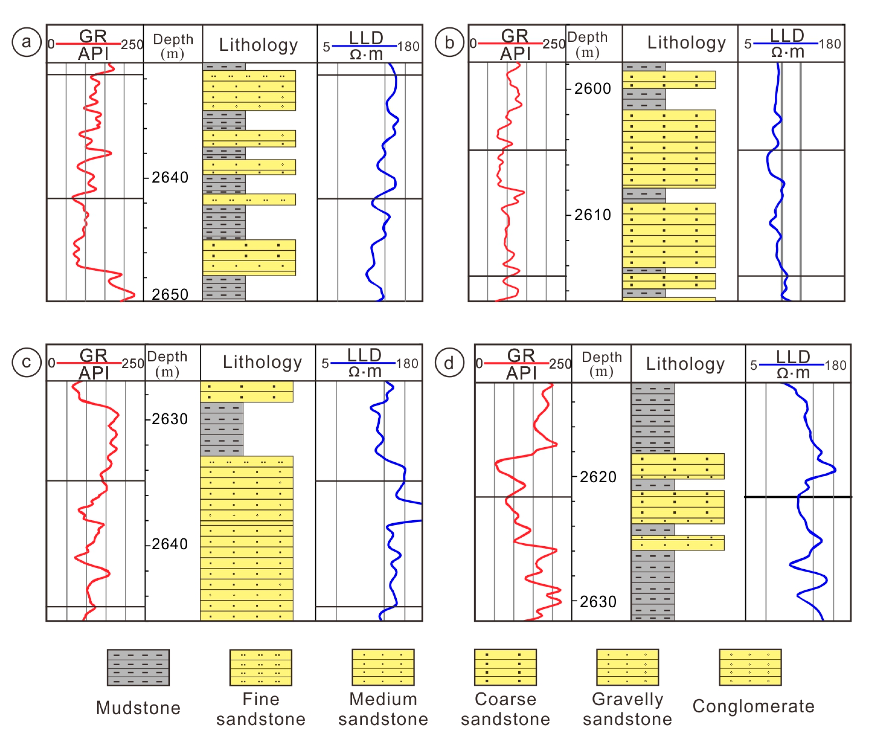
Braided river belt is characterized by a wide and shallow river, minor curvature, unfixed channel, high net-to-gross ratio, and the growth of channel bar and is formed by many stages, multiple bifurcations, and convergence. The lithology is primarily gray-white gravelly coarse sandstone, gray-white coarse sandstone, and gray-white medium-coarse sandstone, with massive and parallel bedding. The gamma-ray (GR) logging curves are mostly toothed box type, with an overall positive rhythm of lower coarse and upper fine (
Figure 5a). The profile structure is studied and separated into river and floodplain subfacies based on core observation, sedimentary facies markers, and logging curve data.
4.1.2. Floodplain
Since the riverbeds in braided rivers are not fixed, the floodplain microfacies are extremely undeveloped in the braided river depositional system, and the thickness is thin for a series of fine-grained deposits. The predominant lithology is dark-gray mudstone with silty strips intercalated locally. Massive horizontal bedding is prevalent, with wavy-lenticular and wavy-flasher bedding also present. The GR logging curves are typically flat baseline or low-amplitude toothed linear, often eroded by the overlying river subfacies deposits, with no evident rhythmicity.
4.2. 4-Level Architecture Unit
In the braided river system, the river is the major facies in sandstone deposition. According to the core observation, single-well facies analysis, and logging curve data in the study area, braided river subfacies are separated into two microfacies types: braided channel and channel bar. On the logging curve data, the channel bar and the braided channel have distinct vertical sequences, and the grain size and sandstone thickness of the channel bar in the same braided river are larger than the braided channel.
4.2.1. Channel Bar
The channel bar architectural unit is the primary body of braided riverbed deposition, and its formation and modification are mostly during floods. The rhythm of channel bar is complicated as a consequence of multi-phase deposition, and the thickness is high, generally larger than 3 m. The lithology is mainly gray-white gravelly sandstone and medium-coarse sandstone. Massive, large-wedge, trough and plate cross-bedding, as well as parallel bedding, characterize the sedimentary formation. GR curve logging morphology is dominated by toothed box type, smooth box type, and box-bell type. Smooth box top and bottom are both in abrupt contact with mudstone, reflecting hydrodynamic characteristics of sufficient material source, strong and stable. Meanwhile toothed box top and bottom are both in abrupt contact, reflecting the characteristics of strong but unstable hydrodynamic conditions, with frequent alternation of strength and weakness (
Figure 5b). The vertical depositional sequence at the head of the channel bar is either an overall massive grain sequence or an anti-rhyme with upward coarsening grain sequence. Meanwhile, the depositional sequence at the tail of the channel bar has an upward refinement of grain size and upward decrease in accretion thickness.
4.2.2. Braided Channel
The braided channel sand body is generally thinner than the channel bar sand body, with gray-white gravelly sandstone, conglomerate, medium-coarse sandstone, and fine sandstone lithologies forming the majority of the braided channel. The laminae are mainly massive bedding, large-plate, and trough cross-bedding and parallel bedding. GR curve logging pattern is mainly micro-toothed box type or bell type, with noticeable upward thinning sedimentary gyrations. The top and bottom of the micro-toothed box type are all abruptly contacted, usually consisting of several upward gradually thinning positive grain sequences, reflecting the depositional characteristics of alternating hydrodynamic conditions. The bottom of the bell type is abruptly contacted with mudstone, corresponding to bottom scouring, and the top is progressively contacted with mudstone, with positive grain sequence structure, representing the gradually weakening hydrodynamic characteristics (
Figure 5c).
4.3. 3-Level Architecture Unit
There are two different types of 3-level architecture units: interlayer and accretion body, within the channel bar. Within a single channel bar, 2–3 interlayers develop, splitting the channel bar into 3–4 stages of accretion body. The emphasis in this modeling is on depicting the spreading features and size inside the single channel bar, which are all intra-channel bar accretion bodies, with the exception of the interlayer. So, the accretionary bodies will not be shown individually in this work in order to characterize the spreading and superimposition patterns of the channel bars. The interlayer is formed in layers inside the channel bar. The lithology is mainly gray-white mudstone or siltstone. The laminae are mostly horizontal bedding, with some wave bedding. The GR curve logging returns a low amplitude, without evident rhythmic characteristics (
Figure 5d).
5. Results
In the study area, the H1 section of the Daniudi gas field focuses on characterizing the 5–3 level architectural unit (
Table 1). In this modeling study, each level of architectural unit will be inscribed sequentially and level by level, embedding the next hierarchy of architectural unit into the previously inscribed architectural model. The floodplain and braided river belt were modeled as the first hierarchy of architectural modeling, represented by the 5-level architectural model. Based on the various levels of the architectural unit, the second hierarchy of the architectural model is created by carving the channel bar and braided channel within the braided river belt of the architectural model in the first hierarchy. Three architectural elements—the floodplain (5-level architectural unit), braided channel (4-level architectural unit), and channel bar (4-level architectural unit)—are included in the second hierarchy of the architectural model. As a result, they are represented by the 5–4 level architectural model. The interlayer is established inside the channel bar of the second architectural hierarchy in order to simulate a third architectural hierarchy. The architectural model in the third hierarchy is represented by a 5–3 level architectural model, which incorporates four architectural elements: floodplain (5-level architectural unit), braided channel (4-level architectural unit), channel bar (4-level architectural unit), and interlayer (3-level architectural unit).
A multiple-level, embedded modeling strategy was used in this study, and the SNISIM algorithm from multiple-point geostatistical was utilized to inscribe a braided river reservoir model based on the architectural unit in this study, which included well data and constraints from previous geological research results.
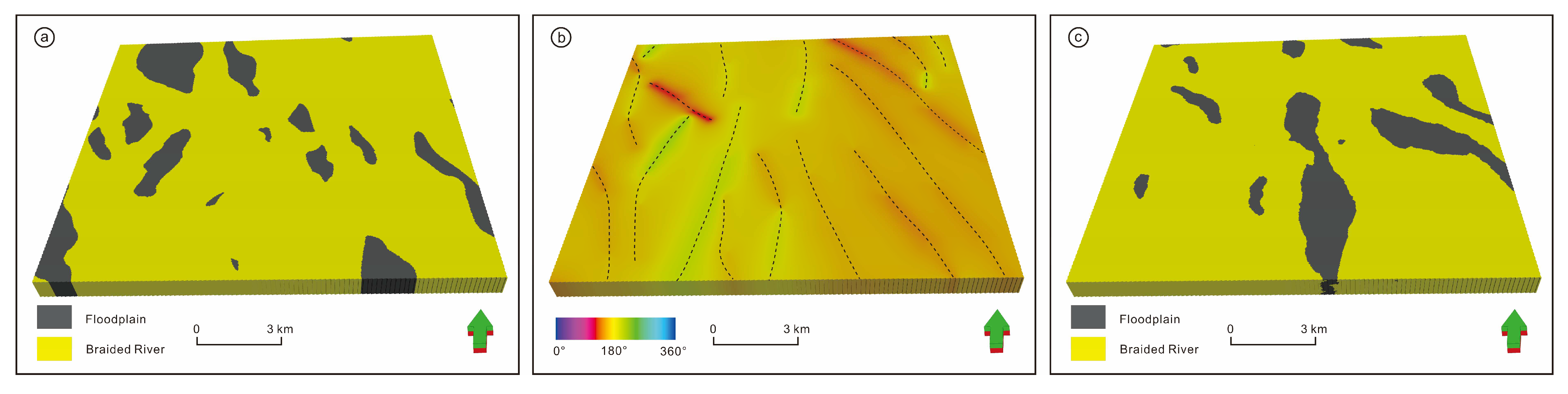
5.1. First Hierarchy 5-Level Architecture Modeling
The well data were initially divided into two facies types before constructing the first hierarchical of the 5-level architecture model: floodplain mudstone facies (code 0) and braided river sandstone facies (code 1), as conditional data 1 (
Figure 6). The braided river sand body was bounded by a 20% net-to-gross ratio to construct a single-stage sedimentary facies map, and it was built as the first hierarchical TI 1-1 using a deterministic modeling method (
Figure 7a).
The location of the braided channel and preliminary morphology were determined by comparing the continuous well profiles of adjacent wells, combining the thickness difference method and the contour method, and analyzing the lithology, interlayer distribution, and logging curve morphology for similarity. Secondly, the single wells representing the box curve of the sand body in the center of the river channel were counted using the method of projecting the GR curve logging onto the well map. The sand bodies in the center of the river channel were connected, in turn, and their extension trajectories indicated the extension direction of the river channel to obtain the main streamline in each stage. Finally, the directional attribute body for each stage of the braided river was established (
Figure 7b). The training image was used to simulate the first hierarchical of the model MPS-1 using a multiple-point geostatistical modeling method through directional attribute body restrictions based on the conditional data 1 (
Figure 7c).
5.2. Second Hierarchy 5–4 Level Architecture Modeling
The single sand body scale of the 4-level architecture unit mainly refers to the scale of the channel bar and braided channel located inside the same braided river. According to the statistics of single well division, architecture interface identification, and profile comparison results, the single-stage braided channel depth of H1 in the research area is 1–22 m, width is 7–320 m, single small channel bar depth is 3–9 m, width is 80–330 m, length is 240–1000 m, large composite channel bar depth is 9–30m, width is 330–1500 m, length is 1000–4200 m, and the overall characteristics were of wide bar and narrow channel [
41]. Based on condition data 1, the division of the sandstone facies (code 1) based on the comparison of logging curves and core photos is added to the channel bar architecture unit (code 2) as condition data 2 (
Figure 6).
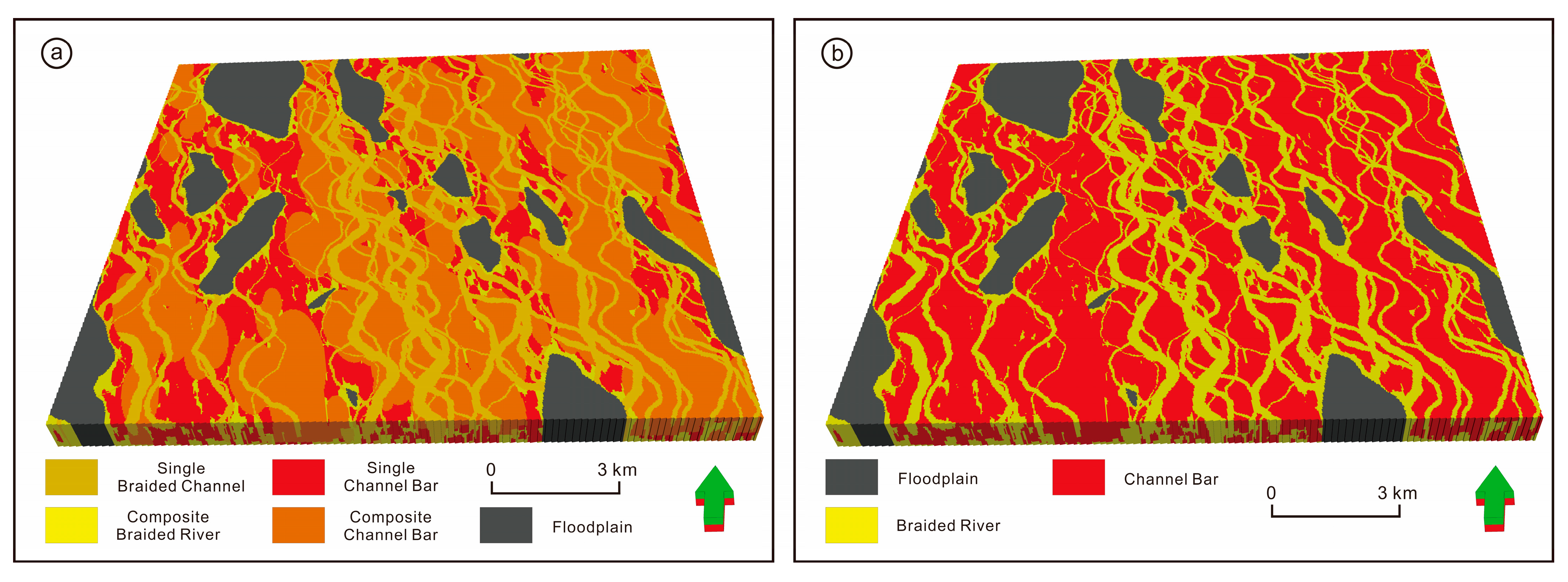
The sandstone facies in the first hierarchical is used as the background for the second hierarchical model. The braided channel (code 3) and channel bar (code 2 for a single small channel bar and code 5 for a large composite channel bar) microfacies are inscribed inside the sandstone facies. The TI 2-1 of the second hierarchical 5–4 level architecture unit is built using the object-based method combined with the size of the architecture unit from the research data (
Figure 8a).
To match the facies codes in the training image with the condition data, the TI 2-1 was processed using the following strategy: merging the braided channel (code 3) with the braided river sand body (code 1) and merging the large composite channel bar (code 4) with the single small channel bar (code 2) to obtain the TI 2-2 matched with the 5–4 level architecture unit (
Figure 8b).
The second hierarchical of microfacies modeling MPS-2 was simulated using a multiple-point geostatistical modeling method (
Figure 9), based on the microfacies divided by 5–4 levels of architecture units, paired with TI 2-2.
5.3. Third Hierarchy 5–3 Level Architecture Modeling
The interlayer of the 3-level architecture unit is a muddy or silty deposit that develops in layers inside the tail of the channel bar. The interlayer (code 5) division is added to the channel bar microfacies (code 2), as the condition data 3 (
Figure 6), before the third hierarchical modeling by combining the logging curve characteristics and core analysis. In constructing the third hierarchical model based on the 5–3 level architecture, a cube with a width of 1000 m, a length of 3000 m, and a depth of 21 m are inscribed as a composite channel bar. The background is the second hierarchical channel bar microfacies (code 2), and three interlayers are quantitatively inserted inside it as the TI 3-1 (
Figure 10).
Based on the results of the second hierarchical model, a multiple-point geostatistical modeling method was used to establish a reservoir architecture model MPS-3 for the study area using the conditional data 3 and TI 3-1 (
Figure 11).
5.4. Comparison of Simulation Results of Different Hierarchies of Methods
The simulation results of the architecture models at different hierarchies were counted and found (
Table 2): 14.5% of developing floodplains and 85.5% of growing braided river belts in the 5-level architecture model. The outcomes of the 5-level architecture model serve as the foundation for the 5–4 level architecture model. Within the braided river belt, two kinds of architectural elements—braided channels (29.4%) and channel bars (56.1%)—are simulated, while the position, shape, and proportion of floodplain development are kept constant. A 5–3 level architectural model was established using the 5–4 level architectural model as a foundation. At this point, it is vital to ensure that the floodplain and braided channels remain unchanged, and that the interlayer is quantitatively and randomly inserted within the channel bar. In comparison to the 5–4 level architectural model, the channel bar develops 0.8% of the interlayer, and the proportion of the remaining channel bar is 55.3%. The results of the first hierarchy of simulation determined the extent and morphology of the braided river belt (
Figure 12a). The results of the second hierarchy of simulation not only identified the position and morphological characteristics of the channel bar, but also modeled the interactions between the channel bar and braided channel (
Figure 12b). The interlayer spread was quantitatively and arbitrarily inserted inside the channel bar at the third hierarchy of simulation, using the interlayer scale data [
41] (
Figure 12c). This is one of the reasons we opted to construct the training images for several hierarchies, and then simulate them one at a time using multiple-point geostatistical. For instance, if a training image is built in a hierarchical way using the floodplain as the background facies, the braided river belt would be simulated first, followed by the braided channel, channel bar, and interlayer injected into the channel bar. All architectural elements are developed in a single training image, and some issues appear in the simulations’ results when the SINSIM algorithm is used. For example, the contact connections of the various architectural elements will not be well represented, and the channel bar may develop in the floodplain, disobeying our geological knowledge.
5.5. Comparison of Simulation Results of Different Methods
Comparisons between the results of traditional two-point geostatistical simulation on the profile and simulation results from a hierarchical multiple-point geostatistical modeling method based on the braided river reservoir architecture are made. The results of the architecture model profiles simulated by the hierarchical multiple-point geostatistical method show that the morphological characteristics of the braided channel and the channel bar are well-reproduced, with a clear facies interface between the two and a good representation of the contact relationships between the architecture units (
Figure 13a). The channel bar has a flat-bottom and convex-top, and the braided channel has a convex-bottom and flat-top morphology in profile, consistent with geological understanding. The model profile, as shown in
Figure 13b, was simulated using the sequential indication simulation method in traditional two-point geostatistical, based on the size of each architecture unit obtained from the architectural feature analysis and the calculated variogram suitable for different architecture units. While the simulation results based on the sequential indicative simulation method fully match the condition data, they do not accurately replicate the morphological characteristics of each architecture, and the position and size of the interlayer are rather random.
5.6. Comparison of Pattern Similarity
As an example, the training image TI-2 of the second hierarchy’s 5–3 level architecture and the simulation result MPS-2 were tested for the similarity of the two patterns. Obviously, the degree of braided channel curvature, density of channel bar distribution, and contact relationships between architecture units in the model maintain a high degree of consistency with the training images, successfully reproducing the priori geological structure and statistical features present in the training images (
Figure 8b and
Figure 9). The braided channel and channel bar morphology, as well as the inter-cutting and superimposition relationships, are better reproduced in the results of the profile in
Figure 12b.
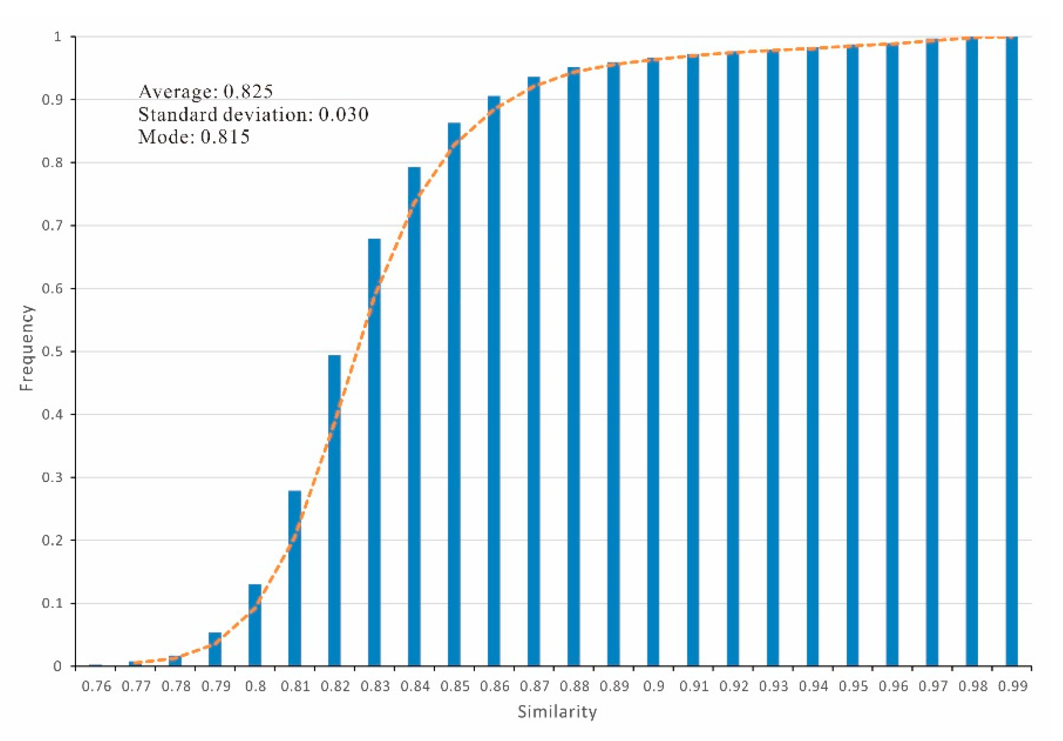
Figure 14 shows a histogram of similarity statistics for the simulated realization of the data patterns corresponding to the most similar data patterns in the training images. The ability of MPS-2 to reproduce the TI-2 a priori geological pattern of the training image is compared. The MPS-2 model has a minor deviation from the pattern reproduction rate, which indicates that MPS-2 is better able to reproduce the a priori geological patterns of the training images, according to the mean, standard deviation, and mode of the histograms (
Figure 14).
6. Conclusions
- (1)
To divide the 5–3 level architecture units in the Daniudi gas field, a fine-grained dissection of the interior of the sandy braided river reservoir was performed. In addition, a progressive modeling method based on hierarchical, level-by-level embedding was proposed to establish a sedimentary microfacies model of the sandy braided river reservoir based on different level architecture.
- (2)
A multiple-point geostatistical modeling method is used to build 5-level, 5–4-level, and 5–3-level architecture models through a hierarchical modeling strategy, with the model results of the next level being embedded into the model results of the previous level, resulting in a set of modeling methods suitable for the Daniudi gas field.
- (3)
An established method based on the combination of qualitative architecture anatomy and quantitative scale of the architecture unit was used to create a 3D fine architecture model for H1 of the Daniudi, which reproduces the morphology and scale of the braided river reservoir and improves the accuracy of the internal architecture modeling of the braided river sand body reservoir.
Author Contributions
Data curation, T.L.; Methodology, M.D., S.L. and W.F.; Project administration, G.R.; Software, X.Z.; Validation, X.L. and Y.G.; Writing—original draft, M.D. All authors have read and agreed to the published version of the manuscript.
Funding
This work was supported by The National Natural Science Foundation of China (No. 42172172 and No. 42002147), and China Petroleum Science & Technology Innovation Fund (2021DQ02-0106).
Data Availability Statement
All data can be obtained from the corresponding author.
Conflicts of Interest
We declare that we have no financial or personal relationships with other people or organizations that could have an inappropriate effect on our work.
References
- Jia, A.L.; Tang, J.W.; He, D.B.; Ji, Y.C.; Cheng, L.H. Geological Modeling for Sandstone Reservoirs with Low Permeability and Strong Heterogeneity in Sulige Gasfield. China Pet. Explor. 2007, 12, 12–16. [Google Scholar]
- Chen, S.Z.; Lin, C.Y.; Ren, L.H.; Liu, W.J.; Chen, H.P.; Huang, W.S. Establishment of the Depositional Model of Sandy Braided River: A Case from the H Block in Orinoco Heavy Oil Belt, Venezuela. Acta Sedimentol. Sin. 2015, 33, 965–971. [Google Scholar]
- Miall, A.D. The Gology of Fluvial Deposits; Springer: Berlin/Heidelberg, Germany, 1996; pp. 75–178. [Google Scholar]
- Qiao, Y.P.; Qiu, L.W.; Shao, X.J.; Wang, J.; Song, F.; Wang, Y.L.; Tang, L.L.; Zhang, Y.G. Research progress on characterization of braided river reservoir architecture. Pet. Geol. Recovery Effic. 2017, 24, 34–42. [Google Scholar]
- Zhang, C.M. Hierarchy analysis in reservoir researches. Oil Gas Geol. 1992, 13, 344–350. [Google Scholar]
- Wang, M.; Mu, L.X.; Zhao, G.L.; Wang, Y.X. Architecture analysis of reservoirs in branching and wandering based braided rivers: Taking FN field, Sudan as an example. Earth Sci. Front. 2017, 24, 246–256. [Google Scholar]
- Zhou, L.; Lv, C.B.; Ji, Y.L.; Li, T.L.; Ran, A.H.; Lu, Y.L.; Liu, T.Y.; Xie, L.L.; Wei, W. Reservoir architecture pattern analysis of distal shallow water braided delta front: A case study of L18 fault block, Liuxi Oilfield, Raoyang sag, Jizhong Depression. J. Palaeogeogr. 2019, 21, 959–970. [Google Scholar]
- Zhu, W.H.; Wu, S.H.; Yin, Z.J.; Han, T.; Wu, Y.M.; Liu, Y.; Feng, W.J.; Luo, Y.N.; Cao, C. Braided river delta outcrop architecture: A case study of Triassic Huangshanjie Formation in Kuche depression, Tarim Basin, NW China. Pet. Explor. Dev. 2016, 43, 482–489. [Google Scholar] [CrossRef]
- Sun, T.J.; Mu, L.X.; Wu, X.H.; Zhao, G.L.; Xu, F.; Wang, Z.J.; Qin, Z.; Fang, Z.Q. A quantitative method for architectural characterization of sandy braided-river reservoirs:taking Hegli oilfield of Muglad Basin in Sudan as an example. Acta Pet. Sin. 2014, 35, 715–724. [Google Scholar]
- Duan, Z.Q.; Li, J.B.; Bai, Y.Q.; Li, F.P.; Xue, W.; Sun, Y.H.; Li, D.Y. Configuration characterization of the braided river reservoirs and its controls on the spatial distribution of the gas saturation: Taking SX infill well block in Sulige Gas Field as an example. Pet. Geol. Oilfield Dev. Daqing 2020, 39, 1–9. [Google Scholar]
- Qin, X.F.; Qi, R.; Li, W.; Chen, X.M. Braided channel architecture analysis and semi-quantitative seismic prediction for channel bars in P1x1 of the Hangjinqi area, Ordos basin, China. Geophys. Prospect. Pet. 2019, 58, 572–579. [Google Scholar]
- Labourdette, R.; Jones, R.R. Characterization of fluvial architectural elements using a three-dimensional outcrop data set: Escanilla braided system, South-Central Pyrenees, Spain. Geosphere 2007, 3, 422–434. [Google Scholar] [CrossRef]
- Wu, X.J.; Su, H.B.; Zhang, S.J.; Feng, L.J.; Wang, J.; Yin, S.L. Architecture Anatomy and Hierarchical Modeling of Sand-Gravel Braided River Reservoirs: A Case study of Zhong32 wells area, Qigu Formation reservoir, Fengceng oilfield. Acta Sedimentol. Sin. 2020, 38, 933–945. [Google Scholar]
- Bai, Z.Q. Study on the 3D Architecture geological modeling of braided fluvial sandbody. J. Southwest Pet. Univ. Sci. Technol. Ed. 2011, 32, 21–24. [Google Scholar]
- Yin, Y.S.; Zhang, C.M.; Yin, T.J.; Zhao, L. 3D Hierarchical Modeling of the Braided Channel Reservoir of Saertu Oilfield. J. Southwest Pet. Univ. Sci. Technol. Ed. 2012, 34, 13–18. [Google Scholar]
- Ma, Z.X.; Wu, Z.; Zhang, J.; Bai, Y.Q.; Li, F.P.; Fu, B.; Bai, H. Static and dynamic information fusion based reservoir architecture characterization and 3D geological modeling technology for braided river reservoirs. Nat. Gas Ind. 2022, 42, 146–158. [Google Scholar]
- Ma, Z.X.; Fu, B.; Wang, W.S.; Luo, C.Y.; Zhang, J.; Zhang, C.Y.; Wei, Q.S. Horizontal well geosteering strategies in braided river reservoir based on hierarchical analysis. Nat. Gas Geosci. 2016, 27, 1380–1387. [Google Scholar]
- Chen, D.Y. Characterization of Braided River Reservoir Architecture in Northeastern Ordos Basin—Based on the Study of He 8 Member on Fugu Tianshengqiao Outcrop. Master Thesis, Chengdu University of Technology, Chengdu, China, 2019. [Google Scholar]
- Xu, Z.B.; Shen, C.S.; Chen, Y.K.; Kang, K.; Luo, X.B.; He, X.R.; Li, L.; Zhang, B.W. Architecture Characterization for Sandy Braided River Reservoir and Controlling Factors of Remaining Oil Distribution—A case study of Poilfield (Neogene), Bohai offshore, China. Acta Sedimentol. Sin. 2016, 34, 375–385. [Google Scholar]
- Guo, Z.; Sun, L.D.; Jia, A.L.; Lu, T. 3D geological modeling for tight sand gas reservoir of braided river facies. Pet. Explor. Dev. 2015, 42, 76–83. [Google Scholar] [CrossRef]
- Li, Z.D.; Pang, H.; Xu, J.Z.; Li, Z.; Zhang, H.X.; Liu, Y.K. Case study of sandbody architecture and quantitative parameters of the far-source sandy braided river: Saertu Oilfield, Daqing, China. J. Pet. Sci. Eng. 2019, 181, 106249. [Google Scholar] [CrossRef]
- Li, S.L.; Yu, X.H.; Jin, J.L. Sedimentary Microfacies and Porosity Modeling of Deep-Water Sandy Debris Flows by Combinging Sedimentary Patterns with Seismic Data: An Example from Unit I of Gas Field A, South China Sea. Acta Geol. Sin. Engl. Ed. 2016, 90, 182–194. [Google Scholar]
- Li, S.H.; Dou, M.J.; Yu, J.B.; Shi, J.H.; Yu, S.Y. Multiple trend integration method based on depositional model and its application in glutenite reservoir modeling. Interpretation 2022, 11, SA77. [Google Scholar] [CrossRef]
- Klise, K.A.; Weissmann, G.S.; McKenna, S.A.; Nichols, E.M.; Frechette, J.D.; Wawrzyniec, T.F.; Tidwell, V.C. Exploring solute transport and streamline connectivity using lidar-based outcrop images and geostatistical representations of heterogeneity. Water Resour. Res. 2009, 45, W05413. [Google Scholar] [CrossRef] [Green Version]
- Niu, B.; Gao, X.J.; Zhao, Y.C.; Song, B.Q.; Zhang, D.F.; Deng, X.J. Architecture characterization and modeling of channel bar in paleo-braided river: A case study of dense well pattern area of Sazhong in Daqing oilfield. Acta Pet. Sin. 2015, 36, 89–100. [Google Scholar]
- Seifert, D.; Jensen, J.L. Object and Pixel-Based Reservoir Modeling of a Braided Fluvial Reservoir. Math. Geol. 2000, 32, 581–603. [Google Scholar] [CrossRef]
- Ramanathan, R.; Guin, A.; Ritzi, R.W.; Dominic, D.F.; Freedman, V.L.; Scheibe, T.D.; Lunt, I.A. Simulating the heterogeneity in braided channel belt deposits: 1. A geometric-based methodology and code. Water Resour. 2010, 46, W04515. [Google Scholar]
- Huber, E.; Caers, J.; Huggenberger, P. A 3D object-based model to simulate highly-heterogeneous, coarse, braided river deposits. In Proceedings of the AGU 2016 Fall Meeting, San Francisco, CA, USA, 12–16 December 2017. [Google Scholar]
- Liu, Y.M.; Hou, J.G.; Song, B.Q.; Zhou, X.M.; Chen, H.K.; Zhang, L.M. Characterization of interlayers within braided-river thick sandstones: A case study on the Lamadian Oilfield in Daqing. Acta Pet. Sin. 2011, 32, 836–841. [Google Scholar]
- Pirot, G.; Straubhaar, J.; Renard, P. A pseudo genetic model of coarse braided-river deposits. Water Resour. Res. 2015, 51, 9595–9611. [Google Scholar] [CrossRef] [Green Version]
- Xun, X.Q. Geological Model of D66 Area Daniudi Gas Field in Ordos Basin. Master Thesis, China University of Geosciences, Beijing, China, 2014. [Google Scholar]
- Li, L.L.; He, S.; Ma, W.J. Application of stochastic modeling in early description of gas reservoir in new area of Daniudi Gas Field. Fault-Block Oil Gas Field 2010, 17, 280–284. [Google Scholar]
- Fu, J.H.; Wei, X.S.; Ren, J.F. Distribution and genesis of large-scale Upper Palaeozoic lithologic gas reservoirs on Yi Shaan Slope. Pet. Explor. Dev. 2008, 35, 664–667. [Google Scholar] [CrossRef]
- Xu, N.N.; Zhang, S.P.; Wang, Y.S.; Qiu, L.W. Diagenesis and Pore Formation of the Upper Paleozoic Tight Sandstone in the Northern Area of the Ordos Basin. Acta Sedimentol. Sin. 2022, 40, 422–434. [Google Scholar]
- Anees, A.; Zhang, H.; Ashraf, U.; Wang, R.; Liu, K.; Abbas, A.; Ullah, Z.; Zhang, X.; Duan, L.; Liu, F.; et al. Sedimentary Facies Controls for Reservoir Quality Prediction of Lower Shihezi Member-1 of the Hangjinqi Area, Ordos Basin. Minerals 2022, 12, 126. [Google Scholar] [CrossRef]
- Wu, J.J. Gas Reservoir Evaluation of Tight Sandstone in He-1 Member of Daniudi Gas Field in Ordos Basin. Master Thesis, Chengdu University of Technology, Chengdu, China, 2013. [Google Scholar]
- Xu, Q.H.; Shi, W.Z.; Xie, X.Y.; Zhang, C.M.; Manger, W.L.; Wang, J.; Rao, S. Multichannel systems in an ancient river-dominated delta: Case study of the lower Yanchang Formation, southwest Ordos Basin, China. Can. J. Earth Sci. 2019, 56, 1027–1040. [Google Scholar] [CrossRef]
- Xu, Y.H.; He, D.F. Triassic provenance shifts and tectonic evolution of southeast Ordos Basin, Central China. Palaeogeogr. Palaeoclimatol. Palaeoecol. 2022, 598, 111002. [Google Scholar] [CrossRef]
- Miall, D. Architectural-element analysis: A new method of facies analysis applied to fluvial deposits. Earth-Sci. Rev. 1985, 22, 261–308. [Google Scholar] [CrossRef]
- Wu, S.H. Reservoir Characterization and Modeling; Petroleum Industry Press: Beijing, China, 2010. [Google Scholar]
- Dou, M.J.; Li, S.H.; Lei, T.; Ren, G.L.; Li, X.H.; Guo, Y.; Feng, W.J. Reservoir Modeling of Braided River Reservoirs Based on Geological Knowledge Database: A Case Study of P1x Formation of the Daniudi Gas Field, Ordos Basin, China. Lithosphere Spec. 2022, 13, 6913641. [Google Scholar] [CrossRef]
Figure 1.
Location of study area. (
a) The location of Ordos Basin (after Xu et al., 2019 [
37]). (
b) The location of Daniudi gas field in the research area (after Wu., 2013 [
36]).
Figure 1.
Location of study area. (
a) The location of Ordos Basin (after Xu et al., 2019 [
37]). (
b) The location of Daniudi gas field in the research area (after Wu., 2013 [
36]).
Figure 2.
Stratigraphic column of the Shihezi formation in study area (modified from Xu et al., 2022 [
38] and Anees et al., 2022 [
35]).
Figure 2.
Stratigraphic column of the Shihezi formation in study area (modified from Xu et al., 2022 [
38] and Anees et al., 2022 [
35]).
Figure 3.
Flow chart of hierarchical multiple-point geostatistical modeling based on braided river reservoir architecture.
Figure 3.
Flow chart of hierarchical multiple-point geostatistical modeling based on braided river reservoir architecture.
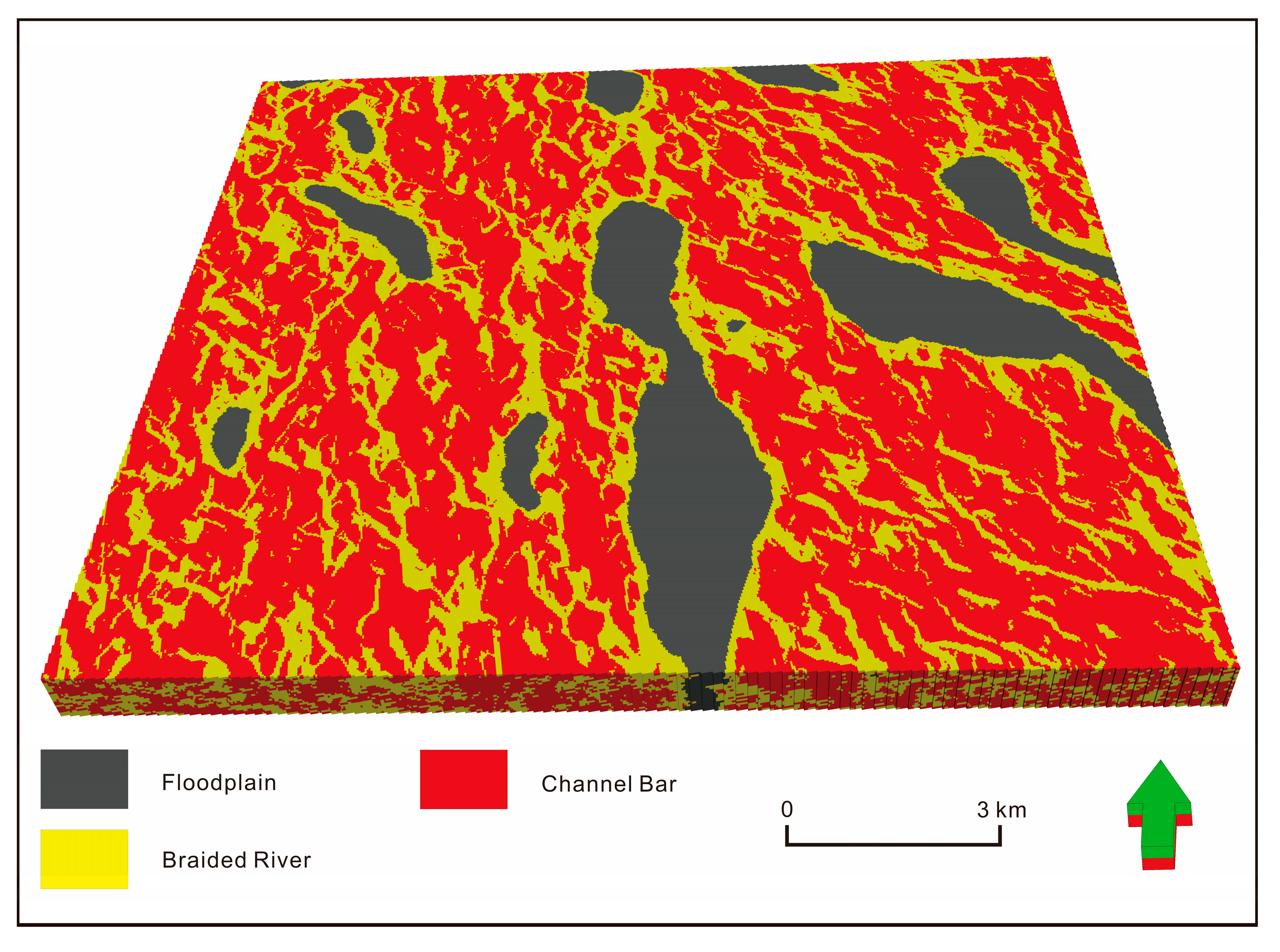
Figure 4.
Distribution of braided river deposits in H1 member of Lower Shihezi Formation.
Figure 4.
Distribution of braided river deposits in H1 member of Lower Shihezi Formation.
Figure 5.
Section structure of braided river sedimentary facies in member H1. (a) Braided river, (b) channel bar, (c) braided channel, (d) interlayer.
Figure 5.
Section structure of braided river sedimentary facies in member H1. (a) Braided river, (b) channel bar, (c) braided channel, (d) interlayer.
Figure 6.
Division of 3 sets of conditional data based on logging curves data and core analysis.
Figure 6.
Division of 3 sets of conditional data based on logging curves data and core analysis.
Figure 7.
First hierarchical modeling. (a) First hierarchical TI 1-1 based on 5-level architecture units, (b) direction attribute body based on main streamline of river, (c) first hierarchical multiple-point geostatistical simulation results MPS-1 based on 5-level architecture units.
Figure 7.
First hierarchical modeling. (a) First hierarchical TI 1-1 based on 5-level architecture units, (b) direction attribute body based on main streamline of river, (c) first hierarchical multiple-point geostatistical simulation results MPS-1 based on 5-level architecture units.
Figure 8.
Second hierarchical TI based on 5–4 level architecture units. (a) Results of differential microfacies simulation TI 2-1, (b) combining microfacies to match conditional data 2 of the TI 2-2.
Figure 8.
Second hierarchical TI based on 5–4 level architecture units. (a) Results of differential microfacies simulation TI 2-1, (b) combining microfacies to match conditional data 2 of the TI 2-2.
Figure 9.
Second hierarchical multiple-point geostatistical simulation results in MPS-2 based on 5–4 level architecture units.
Figure 9.
Second hierarchical multiple-point geostatistical simulation results in MPS-2 based on 5–4 level architecture units.
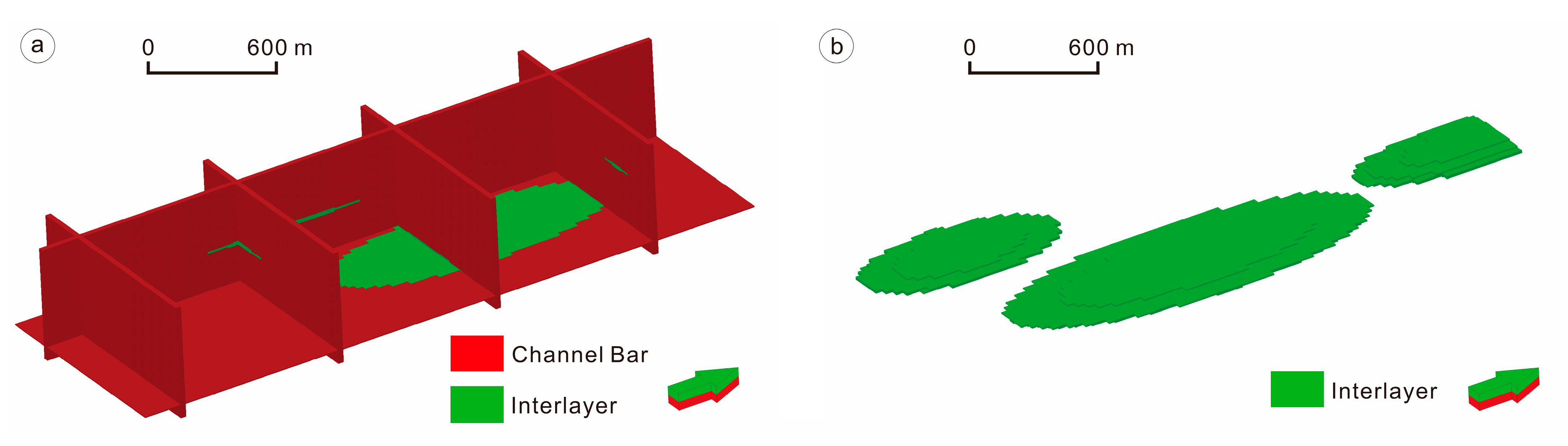
Figure 10.
Third hierarchical TI 3-1 based on 5–3 level architecture units. (a) Fence diagram, (b) interlayer hollowing diagram.
Figure 10.
Third hierarchical TI 3-1 based on 5–3 level architecture units. (a) Fence diagram, (b) interlayer hollowing diagram.
Figure 11.
Third hierarchical simulation results. (a) Third hierarchical multiple-point geostatistical simulation results in MPS-3 based on 5–3 level architecture units. (b) Filter display of interlayer in MPS-3.
Figure 11.
Third hierarchical simulation results. (a) Third hierarchical multiple-point geostatistical simulation results in MPS-3 based on 5–3 level architecture units. (b) Filter display of interlayer in MPS-3.
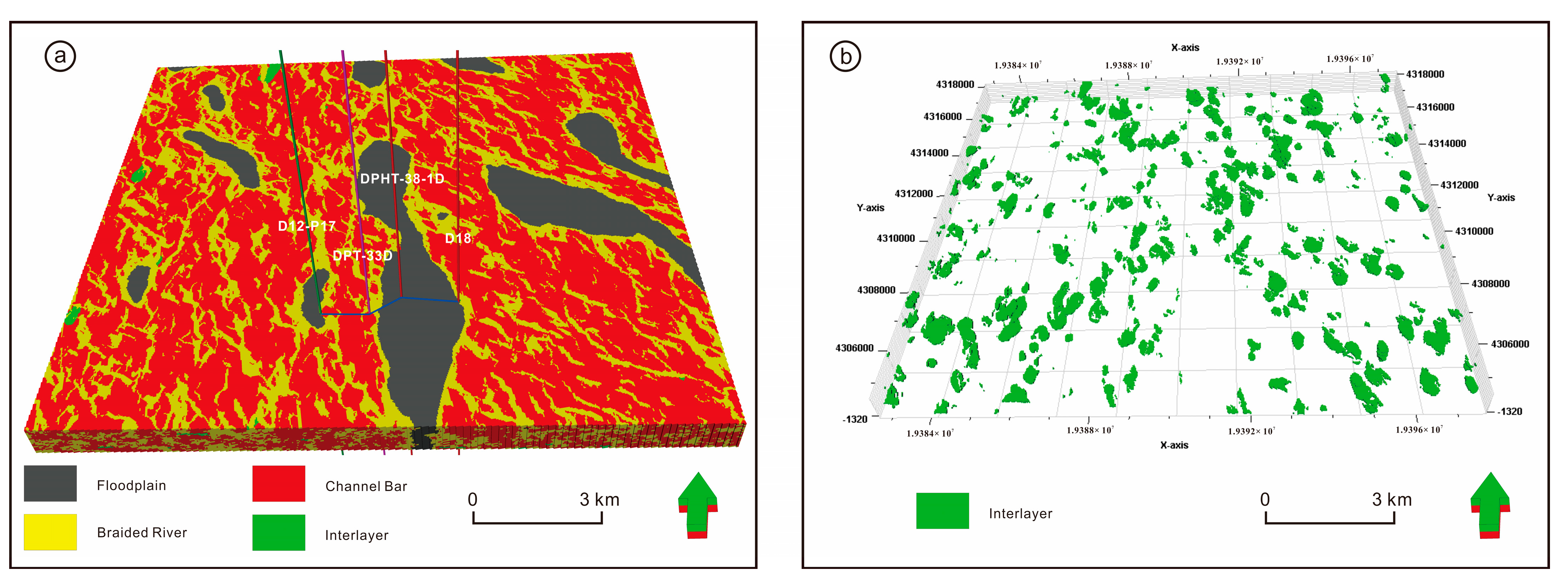
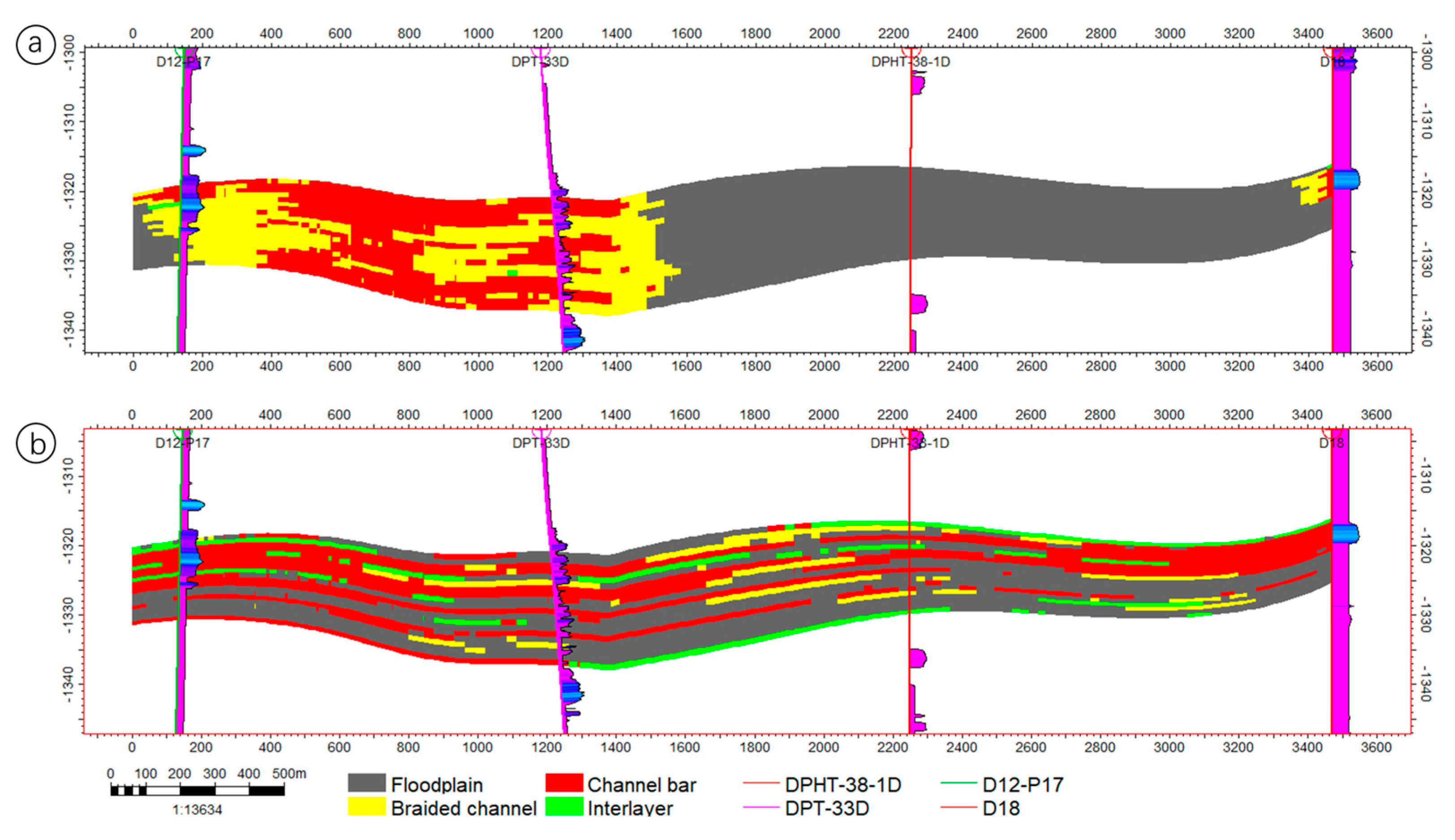
Figure 12.
Results of different hierarchies of architectural model profiles (J = 423): (a) the first hierarchy 5-level architectural model profile results, (b) the second hierarchy 5–4 level architectural model profile results, (c) the third hierarchy 5–3 level architectural model profile results.
Figure 12.
Results of different hierarchies of architectural model profiles (J = 423): (a) the first hierarchy 5-level architectural model profile results, (b) the second hierarchy 5–4 level architectural model profile results, (c) the third hierarchy 5–3 level architectural model profile results.
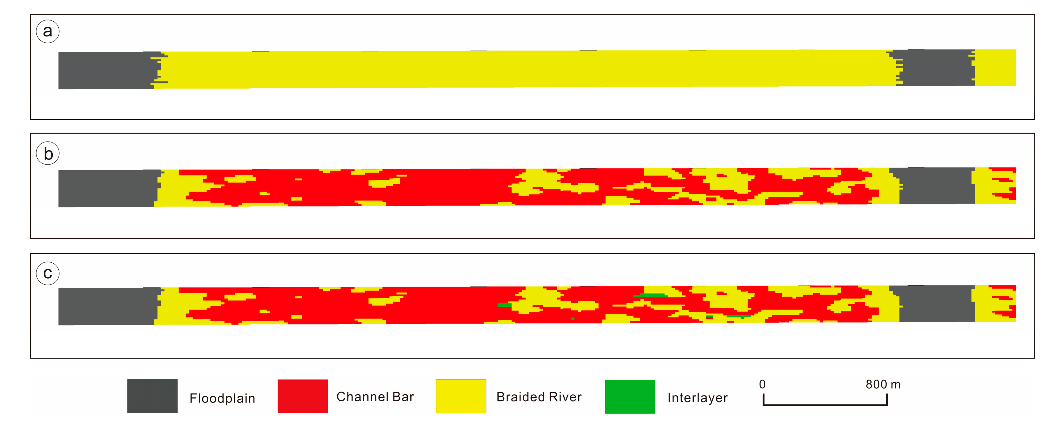
Figure 13.
Cross-sectional view of simulation results of different methods (see
Figure 11a for cross-sectional), (
a) result of multiple point geostatistical simulation profile, (
b) result of sequential indication simulation profile.
Figure 13.
Cross-sectional view of simulation results of different methods (see
Figure 11a for cross-sectional), (
a) result of multiple point geostatistical simulation profile, (
b) result of sequential indication simulation profile.
Figure 14.
MPS-2 reproduces the cumulative frequency of similarity of similar geological patterns in training image TI-2.
Figure 14.
MPS-2 reproduces the cumulative frequency of similarity of similar geological patterns in training image TI-2.
Table 1.
Classification scheme for the H1 Section 5–3 architecture of the Daniudi gas field.
Table 1.
Classification scheme for the H1 Section 5–3 architecture of the Daniudi gas field.
| Type | Fifth-Order Architectural Element | Fourth-Order Architectural Element | Third-Order Architectural Element |
|---|
| Braided river sedimentary | Floodplain | | |
| Braided river belt | Braided channel | |
| Channel bar | Interlayer |
| Accreting bodies |
Table 2.
Proportion of each architectural element in different hierarchies of the model.
Table 2.
Proportion of each architectural element in different hierarchies of the model.
| Architecture Modeling | Floodplain | Braided River Belt |
|---|
| Braided Channel | Channel Bar |
|---|
| | Interlayer |
|---|
| 5-order architecture modeling | 14.5 | 85.5 |
| 5–4 order architecture modeling | 14.5 | 29.4 | 56.1 |
| 5–3 order architecture modeling | 14.5 | 29.4 | 55.3 | 0.8 |
| Publisher’s Note: MDPI stays neutral with regard to jurisdictional claims in published maps and institutional affiliations. |
© 2022 by the authors. Licensee MDPI, Basel, Switzerland. This article is an open access article distributed under the terms and conditions of the Creative Commons Attribution (CC BY) license (https://creativecommons.org/licenses/by/4.0/).

 ,
, 


