Review

Development of Hydraulic Lifting System of Deep-Sea Mineral Resources

1
College of Mechanical and Electrical Engineering, Central South University, Changsha 410083, China
2
National Key Laboratory of Deep Sea Mineral Researches Development and Utilization Technology, Changsha 410012, China
*
Author to whom correspondence should be addressed.
Minerals 2022, 12(10), 1319; https://doi.org/10.3390/min12101319
Submission received: 2 August 2022 / Revised: 1 October 2022 / Accepted: 17 October 2022 / Published: 19 October 2022

Abstract

:
Lifting coarse mineral particles from thousands of meters of seabed to the supportive vessSel is a crucial part of exploitation of deep-sea mineral resources, and the vertical transportation part is a key component of the deep-sea mining system. Three typical vertical transportation schemes are discussed and compared from the aspects of working mechanism, structural scheme, transportation capacity, system efficiency and implementation feasibility in the context of commercial exploitation of deep-sea polymetallic nodules. The conclusion is that the hydraulic pipeline lifting system with a centrifugal pump is a comprehensive scheme. Furthermore, the basic composition and function of the hydraulic lifting system are introduced, and the transportation performance indicators and technical requirements under commercial mining conditions are analyzed. As the key equipment of the lifting system, the structural characteristics, design theory, transportation performance analysis methods and research progress of the lifting pump are described. A 1000 m sea trial was carried out. The lifting system, the tests of the centrifugal pump and the sea trial are introduced.

1. Introduction

The mineral resources in the deep sea are rich in nickel, cobalt, copper, manganese, and other metals, which are the core elements of aerospace, special alloys, lithium batteries, superconductors, and fuel cells, and will become a major direction in solving the resource problem in the future. In the early 1970s, Western developed countries began to carry out research and development of mining technology and equipment for deep-sea polymetallic nodules. At present, some developed countries have enough technical reserves in deep-sea mining technology and are waiting for the arrival of commercial mining opportunity.
Polymetallic nodules, polymetallic sulfides, and cobalt-rich crusts are the most promising deep-sea solid mineral resources. These three mineral resources are different in the depth of water and seabed occurrence states. The proposed mining system is basically similar, consisting of mining vehicles, mining vessels, and lifting systems (also known as “conveying systems”) that transport minerals from the mining vehicles to the mining vessels. The mining vehicles and mineral lifting systems used to collect these minerals are basically the same, except that the collection methods and the design of mining vehicles are quite different due to the different occurrence states. At present, a variety of mineral-lifting schemes have been proposed, and various lifting systems have been introduced [1,2,3,4,5], but most of them only briefly describe the basic composition of these technical schemes, without analyzing the various lifting systems from the perspective of technical principles. A simple mechanical mineral lifting system is the first generation of deep-sea mining mineral lifting systems, mainly including a line bucket lifting system and carrier lifting system.
In the 1960s, a continuous line bucket (CLB) system for collecting and lifting deep-sea polymetallic nodules was proposed by Japanese researchers [5]. Subsequently, an improved double vessel continuous cable hopper scheme was proposed by French researchers [6] to solve the cable entanglement problem. In 1979, French engineers proposed a shuttle mining system [7].
After the end of the line bucket lifting trials in the 1970s, there was no further research on line bucket lifting systems for four decades. In 2016, a new line bucket mineral lifting system was proposed by Australia’s Nautilus Mining Company [8]. However, it was difficult to solve the problem that thousands of meters of cable may become entangled under the action of the ocean current and mining vehicle movement, which made it difficult to apply the cable-bucket lifting system in practice.
Firstly, the research status of the deep-sea mining lifting system is summarized, and the requirements of the deep-sea mining lifting system are analyzed. Further, the comprehensive analysis and comparison of various deep-sea mining lifting systems are made from the perspectives of their lifting performance, system efficiency and feasibility. On the premise of considering the transport capacity requirements of the system, the research progress of the hydraulic lifting system is analyzed, and the structural characteristics, design requirements, solid–liquid two-phase flow simulation research, prototype development, and test progress of the key components of the lifting pump are comprehensively analyzed.

2. Mineral Lifting System Requirements for Deep Sea Mining

To transport these mineral resources at the depth of thousands of meters to a mining vessel, a deep-sea mining mineral lifting system needs to meet the following basic requirements.

2.1. Vertical Transportation of Large Particles

The polymetallic sulfides on the sea floor originate from the mixing of the hydrothermal solution erupted from the sea floor and the cold sea water, and the ore bodies formed are distributed in large blocks at 500–3700 m of the sea floor. Polymetallic nodules occur on the surface of seabed sediments at a depth of 4000~6000 m, usually in a semi-buried state [9,10]. Thus, the mineral resources in the ocean are mostly distributed in the depth of thousands of meters, and these resources need to be transported almost vertically from the bottom to the surface.
According to the exploration experience, to collect polymetallic sulfides and cobalt-rich crust, it is necessary to cut and strip them, forming mineral particles up to tens of centimeters, while the diameter of deep-sea polymetallic nodules is generally between 2 and 10 cm [11,12]. Although the minerals are preliminarily crushed before collecting and transporting, the crushing size should not be too small in order to reduce the crushing energy consumption and the loss caused by excessive ore pulverization. Therefore, the transportation of large particles is a necessary requirement for the transportation of deep-sea mineral resources.

2.2. High Efficiency Delivery

According to the recommendations of the United Nations Expert Group on Deep-sea Mining [13], the commercial production scale of deep-sea polymetallic nodules should not be less than 3 million tons of dry nodules per year (according to the exploration results, the ratio of dry nodules to wet nodules is about 70%, and 3 million tons of dry nodules should correspond to 4.3 million tons of wet nodules). For this scale of production, it is recommended that two sets of mining systems should be employed [14]. The annual production of each system is 1.5 million tons of dry nodules. Each system has a capacity of 6000 t/d and 250 t/h (or 358 tons wet nodules per hour) for 250 working days per year.
On the one hand, due to the long distance of vertical transportation of seabed minerals and high productivity requirements, no matter what kind of mineral transportation method is adopted, the energy consumption in the transportation process will be huge. On the other hand, deep-sea mineral resources are mostly located in the ocean far from the mainland, and energy supply during mining is also a big problem. Therefore, the deep-sea mining mineral lifting system should adopt as low an energy consumption scheme as possible to achieve low energy consumption and high efficiency mining [15].

2.3. Green Mining

To date, the exploitation of deep-sea mineral resources is only experimental and has not yet been commercialized, but the industry has faced challenges in obtaining development support and approvals [16]. According to relevant case studies [1], deep-sea mining activities will cause certain disturbances to the seabed, including artificial waste pollution, light pollution, noise pollution, and plume problems, which will inevitably have negative impacts on the seabed ecosystem environment and biodiversity [2,3]. The United Nations Convention on the Law of the Sea (UNCLOS) sets clear requirements that deep-sea mining needs to meet stringent environmental impact standards for Marine environmental protection. Therefore, environmental protection is an inevitable requirement of deep-sea mining.
In addition to the above requirements, safety, reliability, and service life are also the basic requirements for the design and selection of a deep-sea mining mineral lifting system.

3. Mineral Lifting System Analysis for Deep Sea Mining

The research on mining technology of deep-sea mineral resources began in the 1950s [13]. In this process, there had been a variety of technical prototypes and model machines. Up to now, deep-sea mining mineral lifting systems can be divided into two main categories [4]. One is a simple mechanical lifting system, which mainly includes line bucket lifting and carrier lifting. The other is the pipe lifting system; according to its different lifting power source, it can be divided into an airlifting system and hydraulic pipeline lifting system.

3.1. Pipe Lifting System

After the failure of simple mechanical deep-sea mineral lifting systems, deep-sea mineral pipe lifting systems were inspired by the horizontal long-distance pipeline transport of mineral particles in land-based mining projects. In the late 1970s, a deep-sea mineral pipeline lifting system was proposed by Ocean Management Inc. (OMI), a consortium of countries including the U.S., Japan, Canada, and Germany [17,18]. The system generally consisted of three parts: a subsea mining vehicle that collected nodules on the sea floor, a lifting system for transporting minerals from the seabed to the surface by hydraulic or pneumatic means through pumps and pipes, and a surface support system that provided power and operational support for subsea mining vehicles, lifting systems, performed preliminary dewatering and sorting systems. Figure 1a,b are schematic diagrams of pneumatic pipe lifting and hydraulic pipe lifting in a deep-sea mining system, respectively.
In 1978, a deep-sea mining trial in the Pacific Ocean using an air lifting system was carried out by OMA [19,20]. In 18 h, 550 t of ores were collected from the seabed and transported to the mining vessel, achieving a maximum yield of 50 t/h. In the same period, OMI also carried out deep-sea mining tests in the Pacific Ocean. Two transportation modes, hydraulic lifting and air lifting, were adopted, respectively, to realize vertical transportation of underwater minerals at a depth of 5200 m, in which the air lifting system transported 150 t minerals and the hydraulic lifting system transported 650 t minerals, collecting 800 t minerals in total. The hydraulic lifting system had a maximum capacity of more than 40 t/h, demonstrating the principle of the system and the technical feasibility of deep-sea mining. The power equipment used in the system was a centrifugal pump with diffusers developed by the KSB Pump company of Germany.
In the following decades, the hydraulic lifting system became the mainstream scheme of deep-sea mining lifting system research in various countries. In 1986, Japan carried out eight-stage deep-sea mine pump test research [21], and the pump structure was composed of two symmetrically arranged four-stage pumps. After 1990, deep-sea mining technology received a new round of development. In 1997, India adopted a full hose lifting system [22], and in 2000, the system was tested and verified at 410 m of water depth in the Indian sea jointly with the Engineering Design Institute of the University of Siegen, Germany. It was found that the project was cost-effective and the pipe lifting system was considered to have the most commercial prospects. In 2002, a deep-sea two-stage mixed-flow lifting pump was developed in China [23]. In the 30 m high lifting system, the performance tests of water and slurry were carried out with artificial nodules, and satisfactory results were obtained. In 2005, the basic research on the four-stage deep-sea mining lifting pump was carried out by the Korea Institute of Geoscience and Mineral Resources (KIGAM). Air lifting was one of the pipe lifting systems of minerals [24]; Numerical simulations of a 20 mm maximum particle size through the pump and the performance prediction of the pump under different working conditions were carried out. In 2010, a lifting trial in the Arabian Sea in the depth of 521 m using a full hose mining system was conducted by India [25]. The pump of the system was a duplex positive displacement pump, similar to the land concrete convey pump. The inner diameter of the lifting hose was 75 mm, the maximum particle size was 25 mm, and the maximum flow rate of the pump was 45 m3/h. In 2016, the “Deep-sea Polymetallic nodules Mining Pilot Project” was officially launched in China. By 2021, the project had successfully completed the whole-system linkage test of deep-sea polymetallic nodules exploitation [26,27]. The hydraulic lifting system was adopted, and the reliability and feasibility of the deep-sea mineral hydraulic lifting system was fully verified.
The following is a comparative analysis of two pipe lifting systems from the aspects of principle, productivity, and efficiency.

3.1.1. Air Lifting System

Air lifting is one of the pipe lifting systems of minerals. It makes use of the mining vessel air compressor, high pressure gas injection mineral ascending pipe, high pressure gas in sea water expansion to promote the rising seas, when the water rises faster than the bottom of the sea polymetallic nodules settling velocity in the water will promote the nodules’ rise. Seawater and nodules will be eventually piped to the mining vessel and its basic principle is shown in Figure 2. From the working principle of the air lifting system, it is not difficult to see that the main factors affecting the capacity and energy consumption of an air lifting system are pipe diameter, inlet depth of compressed air, and mineral particle size.
Enlarging the pipe diameter can improve the production capacity, but at the same time, the gas flow rate in the pipeline will also increase. In the case of a mineral particle size of 20 mm and lifting height of 6000 m, in order to meet the lifting system’s capacity of 358 tons of wet nodule per hour, if the pipe diameter is less than 1 m, the gas flow rate will exceed 15 m/s, which will result in the sea water flow state changing into an annular flow state and loss of the ability to lift solid particles [28]. This means that for a mining system with an annual production of 3 million tons of dry nodules, if air lifting is used for mineral lifting, large diameter lifting pipes of more than 1 m must be used. The large diameter pipe will cause many problems, such as increased cost and difficulty in system operation.
The influence of the inlet depth of the compressed air and the particle size of the mineral on the productivity of the pneumatic pipeline lifting system is related to energy consumption [4]. Figure 3 shows the net energy power required for transportation of 3 million tons of nodules per year at a mining water depth of 6000 m with different air inlet depths and different particle diameters (10 mm and 20 mm). As can be seen from the figure, when the compressed air inlet depth is greater than a certain critical value, the system energy consumption value will remain unchanged. On the other hand, the effect of reducing the mineral particle size on energy consumption is not obvious. Considering that excessive reduction of mineral particle size will lead to the reduction of mineral recovery, it is not feasible to improve productivity by reducing the mineral particle size.
According to the above analysis, the productivity and energy efficiency of the pneumatic pipeline lifting system will be restricted by some factors in practical application. According to the calculation and analysis, at the above capacity and system parameter levels, the volume concentration of the solid phase in the solid–liquid two phases in the lifting pipeline is only 3%~4%, far lower than the volume concentration of the solid phase in the hydraulic lifting system, which is more than 12%. Pneumatic conveying is generally less than 15% efficiency [29], so more water must be pumped from the bottom to the surface to achieve the same mineral productivity. For environmental protection purposes, the water pumped to the surface cannot be discharged directly to the surface, but must be injected back below a certain depth. Under the same capacity requirement, the air lifting method will have more water injection than the hydraulic lifting method, which is also a disadvantage of the air lifting method.

3.1.2. Hydraulic Lifting System

The hydraulic lifting way is to install the pump in the underwater pipeline, powered by a pump; the pressure can convert mechanical energy into slurry; the pump needs to overcome the frictional resistance of slurry flow, and the work of slurry density increases the form of the potential energy difference; under the pump installation position, outside pressure, the pressure is lower than the pipe in the pipeline potentials to improve slurry by the sea; the pressure inside the pipeline above the installation position of the pump is higher than the pressure outside the pipe, and the slurry is promoted by the pump. The pressure difference outside the pipeline is generated by the power of the pump, and the up-flow of seawater in the pipeline is formed to lift the nodules to the mining vessel [30].
From the working principle of the hydraulic lifting system, it is not difficult to see that the pressure loss to be overcome in the process of mineral transportation mainly includes tube wall friction loss, local pressure loss, and gravity pressure loss. The main parameters involved in these pressure losses include mineral particle size, slurry concentration, and slurry velocity and flow in the pipeline.
The smaller the mineral particle size is, the smaller the sedimentation velocity is; the smaller the collision energy loss is in the flow process, the higher the fluid transmission efficiency is, and the higher the system energy efficiency is [31]. However, too small a mineral particle size will increase the energy consumption of seabed mineral crushing and reduce mineral recovery. For the exploitation of deep-sea polymetallic nodules, the exploration results show that the particle size of nodules is generally 20~100 mm. Considering the flow capacity of pipelines, especially centrifugal pumps, and the requirements of backflow blocking of pumps in vertical transportation, the maximum particle size of nodules is usually not more than 35 mm [26].
Slurry concentration affects the productivity and efficiency of the lifting system. Equation (1) represents the functional relation vessel between the lifting system efficiency and the conveying volume concentration in hydraulic lifting [4]:
η = C V [   ρ s / ρ s w 1 J m   ]
where η is the lifting system efficiency; C V is the volume concentration of transported particles; ρ s is the density of the wet nodule; ρ s w is the density of the slurry; J m is the total hydraulic gradient of the lifting system.
The lower the concentration of minerals, the more seawater needed to transport the same volume of minerals, resulting in more energy consumption; so the higher the concentration of minerals, the more efficient the system. However, it can be seen from Equation (1) that when the conveying concentration C V increases, the total hydraulic slope J m also increases. When the concentration increases to a certain extent, the lifting efficiency η does not increase greatly, but has a great influence on the lifting resistance. Taking a commercial mining system with a water depth of 5200 m as an example, the lifting capacity of wet nodule per hour is 358 t/h. The calculated lifting system parameters are shown in Table 1 [4]. From the table we can see that, when conveying volume concentration C V ≥ 12%, the efficiency does not increase significantly with the increase of concentration, while the lifting flow is small and the required head is also large. Therefore, it is suggested that the lifting concentration of slurry in commercial mining be selected as 12%, and the calculated system efficiency can reach nearly 70% at this time.
After the system capacity and slurry volume concentration are determined, the slurry flow rate in the riser pipe is determined. At the same slurry flow rate, the slurry flow rate depends on the inner diameter of the lifting pipe. In order to ensure that the polymetallic nodules can be successfully promoted, the slurry flow rate in the hard pipe and the lifting pump should be guaranteed to be 3~5 times the settlement speed of nodules. According to relevant test results and empirical formula, the settling velocity of 30 mm-size mineral nodules in seawater is about 0.7 m/s, and the velocity of slurry should be controlled at 2.1~3.5 m/s. According to the flow and flow rate, the required pipe diameter can be calculated. For a capacity of 358 tons per hour wet nodules, if the flow rate is 3.5 m/s, considering the overall design of the mining system, the pipe diameter should be around 370 mm, which is acceptable for the mining system.
From the above analysis, it is known that the selection of mineral particle size, slurry concentration, slurry velocity and flow in the pipeline, and the diameter of the conveying pipeline are restricted by many factors. Under specific mineral and productivity requirements, the basic parameters of the lifting system are basically fixed. According to the above analysis, for the centrifugal pumping system, its slurry lifting concentration is 12%, and the efficiency can reach nearly 70%.
Considering the transport performance, system efficiency and feasibility of various lifting systems, the centrifugal pump hydraulic lifting system is the most promising deep-sea mining lifting system at present.

4. Research Progress of Hydraulic Lifting Technology

4.1. Basic Composition of Hydraulic Mining System

Based on the latest commercial mining system schemes for deep-sea polymetallic nodules proposed by various countries, the hydraulic lifting system is determined as the most promising deep-sea mining technology [32,33,34,35]. The hydraulic mining system is mainly composed of three parts: an overwater support subsystem and lifting subsystem [13]. Figure 4 shows the overall layout of the mining system.

4.1.1. Overwater Support Subsystem

The overwater support subsystem is the activity center of the hydraulic mining system. In the early stage, it was refitted from an operating vessel with similar performance in the offshore drilling industry [36]. The overwater support subsystem is an important part of the whole hydraulic mining system, which covers the overall system control, positioning control of the vessel, electrical system for kinetic energy supply of lifting equipment, underwater visual monitoring, mineral pretreatment and storage, and the layout and recovery of the whole hydraulic mining system [37]. The overwater support subsystem is responsible for the safe operation of the entire hydraulic mining system and ensures that the operation objectives of the lifting system are completed on schedule.

4.1.2. Lifting Subsystem

The lifting subsystem is mainly responsible for transporting the nodule particles collected by the underwater ore collection subsystem to the surface support subsystem for mineral pretreatment and storage. The underwater layout structure of the subsystem is, from top to bottom: mineral transmission pipeline, deep-sea lifting pump, underwater relay measurement and control station, power measurement and control system and transmission hose connected with the ore collection subsystem. The lifting subsystem is also the critical subsystem of the whole hydraulic mining system. Among them, the deep-sea lifting pump is the most important component of the whole system. For nearly 30 years since the 8th Five-Year Plan period in China, various researchers have continuously carried out relevant technical research on deep-sea lifting pumps [38,39,40,41,42]. During the 13th Five-Year Plan period, the 702 Institute of the China Shipbuilding Corporation further optimized and innovated the underwater relay station system, and further improved the independent design ability of the lifting subsystem in China’s hydraulic mining system.

4.2. Transportation Performance Index and Technical Requirements of Hydraulic Lifting System under Commercial Mining Conditions

Due to the different distribution of mining areas, the enrichment of deep-sea mineral resources of different countries are different. Correspondingly, under the commercial mining conditions, the relevant transportability and technical requirements of the underwater lifting system also are different.
According to the nodule situation in India’s deep-sea mining area and the transportation situation of the hydraulic lifting system, India has preliminarily proposed the transportation performance indicators for resource mining in its deep-sea mining area as follows: the current mining depth of the mining area is 500 m, the maximum particle size of the nodule particles is 25 mm, the maximum slurry concentration transported during lifting is 30%, and the mining volume of nodule particles is 288 t/day [43]. The performance index of mineral nodule transportation for the commercial exploitation of deep-sea mining resources in Japan is a planned annual production of 128,400 t/year. According to the weather conditions of the mining area in Japan, the mining system is planned to work 268 days a year, that is, an average of 4972 t/day [26].
According to the recommendations of the United Nations Expert Group, the commercial mining production of deep-sea polymetallic nodules in China’s mining areas should not be less than 3 million tons of dry nodules, that is, the corresponding wet nodules are 4.3 million tons. In view of this production scale, the international deep-sea mining community generally recommends one to adopt two sets of mining systems. At the same time, considering the variability of offshore weather, it is calculated as 250 days per year, that is, the capacity of each system should be 6000 t/day. The particle size of polymetallic nodules in the corresponding sea area of China is mostly between 2 and 8 cm, while a few particles are a full 20 cm. Therefore, the nodule particles transported in the lifting subsystem should be preliminarily crushed. In the mineral pretreatment in the overwater support subsystem, too fine nodules cannot be screened. Therefore, the crushing requirements for nodule particles in the underwater ore collection system are that the particle size after crushing is between 20 and 50 mm. In order to ensure the safety of China’s hydraulic lifting system and prevent blockage in the deep-sea lifting pump, China requires that the maximum particle size of commercially mined polymetallic nodules is 35 mm. With reference to the transportation experience of land pipelines, it is recommended that the transportation concentration of the transportation pump in commercial exploitation should be between 10 and 12%.
For the self-designed hydraulic lifting system in China, the core component of the whole system to transport nodule particles is the deep-sea lifting pump. From the perspective of structure design, the requirements of the whole conveying system are realized by designing multiple pumps in series. The opening depth of the commercial exploitation pump is planned to be 5200 m. Considering that the total length of the deep-sea hard pipe is 5100 m and the safety factor is taken as 1.05, the corresponding required pump lift is 855 m. According to the lift, 4 pumps are connected in series to meet the requirements. Thus, the basic technical parameters of commercial mining pumps for polymetallic nodules suitable for mining areas in China can be obtained, as shown in Table 2.

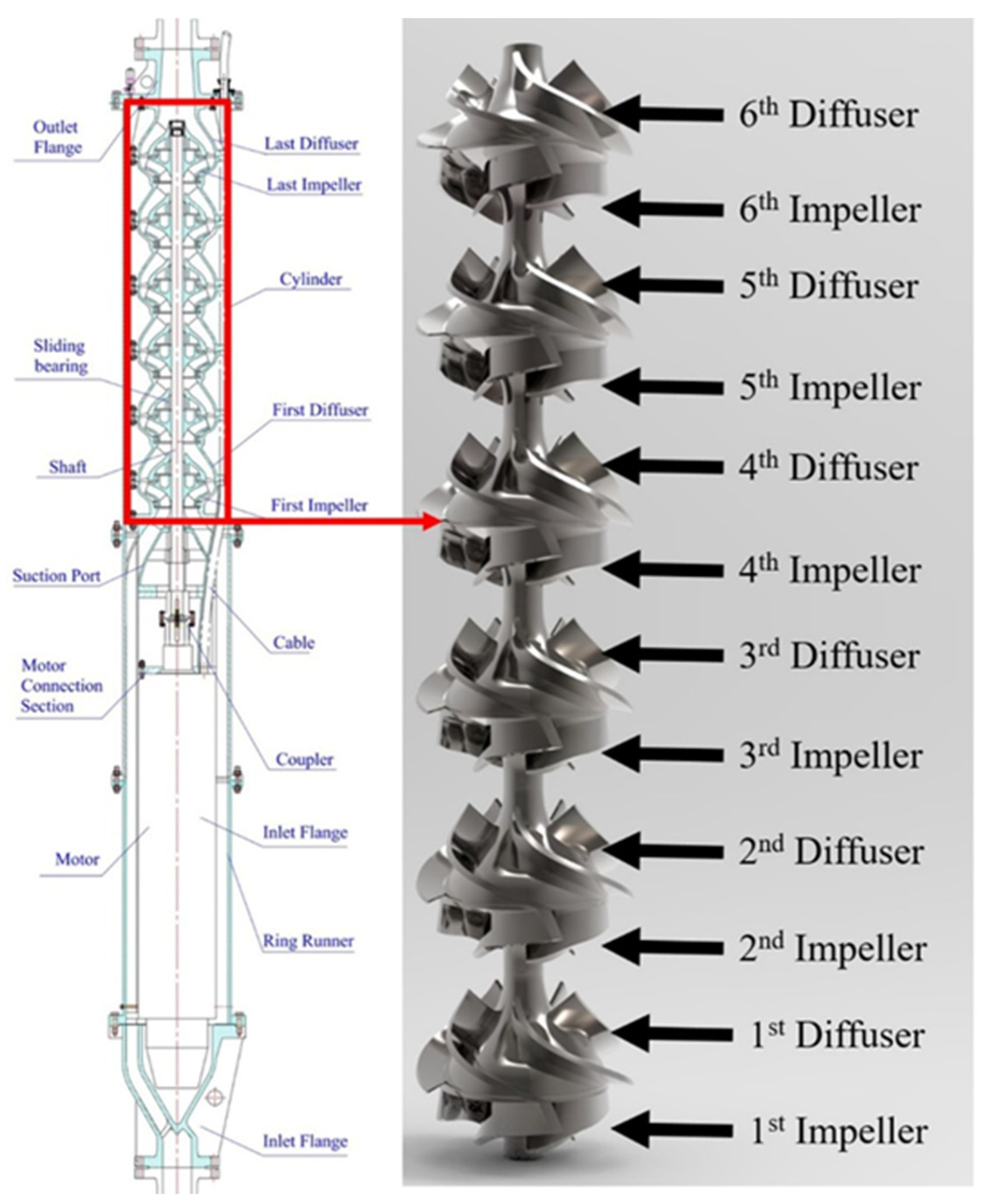
5. The Key Component of the Hydraulic Lifting System—Lifting Pump

5.1. Structural Features and Design Requirements

The hydraulic lifting system includes lifting pipes, lifting pumps, underwater relay stations, conveying hoses, and other components. The lifting pump is required to pressurize the ore slurry in the bottom section of the pipe and convey it to the surface deck system. It has the characteristics of high lift, coarse particles, axial flow, and returnable flow.
Deep-sea mining often requires transporting ore slurry thousands of meters from the seabed to the surface. High lifting pumps are usually composed of multi-stage pumps in series. Larger impeller outlet placement angles, forward impeller blades, and outlet inclination designs can be selected within an appropriate range to improve hydraulic performance [27]. In order to balance the axial forces, some pumps are designed with the motor in the middle and the pump body arranged symmetrically, but such designs usually have backflow problems. A better way to reduce the axial force is to use a balance hole. The initial ore collected by the mining vehicle can reach more than 100 mm, and the maximum is about 20 mm after being crushed by the hydraulic crusher. The slurry contains a large amount of coarse particles of more than 5 mm. When the crushing fails randomly, there may even be some extremely large particles. Therefore, it is necessary for the pump to have a wider flow channel and strong particle flow capacity. To this end, the lifting pump can be designed with a widened flow channel and a smaller number of blades. As shown by the installation form, the central axis of the lifting pump and the motor must be arranged to coincide. The suction inlet and outlet of the centrifugal pump are usually coincident with the central axis of the pipeline. The axial force is balanced by the pulling force of the pipeline, and the kinetic energy of the inlet and outlet can be used to the maximum extent to reduce the hydraulic loss. In order to ensure safety, the lifting system needs to have reflux capacity under emergency conditions, and the ore needs to flow back when the lifting pump is stopped to ensure that it will not be stuck when it is restarted next time [44]. To meet the above requirements, the specific design parameters of the six-stage lifting pump proposed by China‘s 13th Five-Year National Key R & D Program are shown in Table 3 [45], and the design schematic diagram is shown in Figure 5. The enlarged flow design method is adopted to widen the flow channel, and the hydraulic components are designed in combination with the “equal power” and velocity coefficient method.
The working conditions of seabed mining are complex and the flow rate fluctuates greatly, so the pump needs to be designed with “equal power”. When the flow rate deviates from the rated flow point by 50%, the pump power load fluctuation generally does not exceed 10%. The fluctuation of the lift also avoids a large steep drop and prevents the pipeline transportation from being blocked due to insufficient kinetic energy of pipeline transportation [27].

5.2. Current Status of Simulation Research on Solid–Liquid Two-Phase Flow of Lifting Pump

The lifting pump lifts lots of broken nodules and seawater to the surface support system, which is a complex two-phase turbulent flow. At present, there are mainly three types of models in the simulation research of solid–liquid two-phase flow, the Lattice Boltzmann model, the Euler–Euler model, and the Euler–Lagrange model. The Lattice Boltzmann model is suitable for ultrafine particle dynamics simulation and is mainly used in theoretical physics research [46]. The Euler–Euler model makes discrete particles continuous and is suitable for the simulation of fine particles with high concentration and uniform particle size distribution [47]. The Euler–Lagrange model is the mainstream solid–liquid two-phase flow simulation method currently used in engineering research, which can track the force, trajectory, and other parameters of any particle [48].
The solid–liquid two-phase flow simulation based on the Euler–Lagrange model currently mainly includes two simulation methods, CFD–DPM and CFD–DEM, both of which use the Lagrange particle tracking method to simulate nodule particles. The difference is that DPM ignores the particle volume, while DEM considers the impact factors such as particle volume collision and volume fraction through the soft sphere model, which improves the accuracy and reliability of large particle motion and particle dynamics simulations, especially suitable for simulating particle dynamics research of low concentration (volume concentration less than 10%) and coarse particle slurry transportation. In the CFD–DEM coupling simulation of the lifting pump, the particles with a particle size below 3 mm are usually ignored or regarded as a homogeneous slurry mixed with seawater to improve the calculation speed. It was found by Wang [49] et al. that the particle size mainly affects the vortex strength in the pump, and has a limited impact on the hydraulic performance after the calculation and analysis of the solid–liquid two-phase unsteady flow of a single-stage deep-sea mining lifting pump based on CFD–DEM. Ning [50] analyzed and compared the CFD–DEM calculation results with the particle velocity test results (Particle Image Velocimetry (PIV)), and when the grid was dense enough, the simulation results were very close to the experiments, which fully verified that CFD–DEM was effective in simulating particles Accuracy and reliability of kinetics. Deng [27] artificial particle distribution, particle dynamics, and slurry hydraulic performance through CFD–DEM, and compared the experiment, and found that the error of CFD–DEM coupling simulation of slurry hydraulic performance can be controlled within 2%. Huang [51] artificial the volute centrifugal pump under different flow rates based on the EDEM-Fluent coupling platform. When using the Archard wear model, the wear of volute was the largest, accounting for 70% of the total wear. Hu [46] analyzed the particles with different particle sizes in the multistage centrifugal pump by CFD–DEM. The introduction of particle bonding made the simulation more realistic, and the results were highly consistent with the experiment. The result of lifting pump CFD–DEM particle dynamics simulation is shown in Figure 6.
DPM and the DDPM model optimized based on DPM are suitable for simulation scenarios such as high-concentration small particles and pump wear, and can simulate the lifting pump to transport high-concentration slurry containing small particles with a particle size of less than 1 mm. The local slurry velocity in the lifting pump is as high as 20 m/s, and the wear of the overcurrent components is a problem that needs to be considered in the design [52]. Using the DPM model, R. Tarodiya [53,54,55] et al. simulated the delivery of fine particles (<1 mm) by a volute mud pump, and combined it with SEM scanning electron microscopy to analyze the different failure modes of the worn surface. It was found that the wear in the pump was affected by the particle distribution and the impact angle. Using the Finnie wear model, it was predicted by Liu [56] et al. that the wear rate of the over-flow components of the diffusers deep-sea lifting pump under different flow rates, rotational speeds, and different particle concentrations. It was found that the wear rate of the impeller of the diffusers centrifugal pump with the increase of flow rate, the impeller casing wear, and vane working face are the most serious, while the wear rate of the guide vane does not increase significantly, and the wear caused by conveying 10 mm particles is the least.

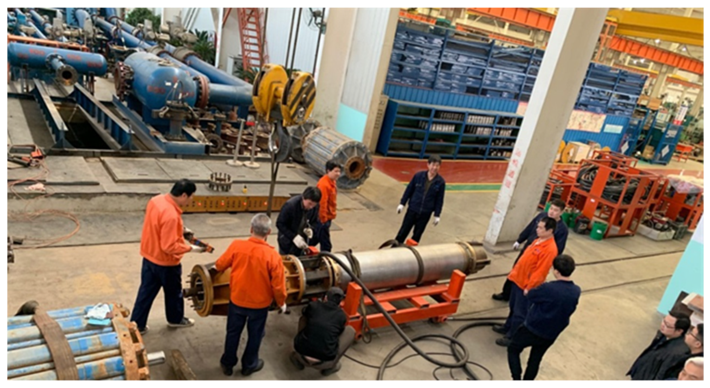
5.3. Progress in Development and Test Research of Lifting Pump Prototype

Lifting pumps in deep-sea mining operations need to transport large particle size distributions in vertical pipelines over a thousand meters, including micron-sized particles to particles with a possible maximum directional size close to 100 mm. The working environment is harsh, and the collision and wear of the overflowing mud on the pump are different from those of ordinary land pumps. The lifting pump needs to consider various complex working conditions such as flow fluctuation, load balance, and emergency return flow.
In the 1970s, German KSB launched a preliminary study, combining the advantages of centrifugal pumps and axial flow pumps with a compromise design, designed three six-stage mixed-flow pumps as shown in Figure 7 [57], and proposed a double suction port. The series 12-stage pump design can deliver a maximum particle size of 25 mm and a rated flow of 500 m3/h. In 1978, the OMI and OMA Group carried out deep-sea polymetallic nodule sea trials of 5200 m and 4570 m, respectively. Fifty tons of minerals were collected by OMI using a six-stage centrifugal pump designed and developed by the KSB Group. During the test, the problem of wear and failure of the lifting pump was found. In 1986, an eight-stage lifting pump of the same type based on the successfully tested two-stage pump was manufactured by Japan’s Ebara Company. The pump design flow was 450 m3/h and the total hydraulic lift was 376 m. During the test, it was found that the pump had a problem of backflow blockage [58].
From 2001 to 2005, the China Changsha Research Institute of mining and metallurgy successfully developed a two-stage lifting pump [59], as shown in Figure 8, with the support of the “Tenth Five-Year Plan” national marine special research program. The pump is 4.6 m long, the maximum outer diameter is 0.93 m, the specific speed is 198, the lift of each stage is 45 m when the flow is 400 m3/h, and the internal efficiency of the clean water pump reaches 60%. The 30 m high lifting comprehensive test system developed in the “Eighth Five-Year Plan of China” has carried out the slurry conveying test, and the maximum lifting particle reaches 50 mm, but the pump still has the problem of blockage. However, it is determined that the future slurry lifting pump in China will take the high specific speed mixed flow pump as the basic development direction.
In 2012, a diaphragm positive displacement pump was developed by Nautilus Mining Company and GE Hydil [60], but the pump was not actually put into sea trial production due to the problem of diaphragm life in subsequent tests. In June 2016, a five-stage slurry pump with high specific speed was developed by China’s Changsha Institute of Mining and Metallurgy, and a 300-m lifting pump pipe test in the South China Sea was successfully carried out [61]. The volume flow rate of conveying slurry reached 500 m3/h, and the amount of tuberculosis was 50 t/h. In general, the hydraulic pipeline lifting system driven by multi-stage centrifugal pumps is still the mainstream technical solution for vertical transportation of deep-sea polymetallic nodules mining. In 2018, a two-stage centrifugal deep-sea mining pump (as shown in Figure 9) was developed by Central South University under the funding of the National Key R&D Program. After testing, the design was improved and a six-stage centrifugal pump of the same type was developed in 2019 (as shown in the Figure 10). The pump successfully carried out the slurry transportation experiment in the land test site. The conveying slurry flow rate is 425 m3/h, the test slurry concentration is 8.6%, and the wet nodules are transported at 73 tons per hour, and the maximum conveying particle size is 23 mm.
Deep-sea mining engineering requires a collection vehicle to collect and crush deep-sea manganese nodules or cobalt rich crusts, mix them with a certain concentration, and then transport them to the surface support system by a lifting pump. Since the 1970s, many countries all over the world have begun to test the development of deep-sea resources and accumulated rich development experience. In 1990, a 79 m sea trial of the hydraulic lifting system was conducted by the Moscow Institute of geological exploration, Russia. In 2009, a 100 m sea trial of the transmission system was conducted by the Korea Institute of Geoscience and Mineral Resources (KIGAM). In 2015, the performances of the lifting pump and buffer station were tested with a truncated lifting pipe of 500 m by the Korea Research Institute of Ships and Ocean Engineering (KRISO). In 2017, a 1600 m lifting system sea trial was conducted by the Japan Oil, Gas, and Metals National Corporation (JOGMEC) [37].
After a lot of preliminary exploration, China proposed the “13th Five-Year Plan” in 2016, and established the “Deep Sea Polymetallic Nodule Mining Test Project” as a key R&D plan. The project focuses on efficient, non-clogging long-distance transportation, green and safe transportation research of ore collection and crushing, deployment, and recovery in complex sea conditions, and intelligent monitoring and analysis in complex environments. Led by the China Oceanic Association, it brings together the research forces of more than ten institutions including the Changsha Research Institute of Mining & Metallurgy, Central South University, China Shipbuilding Industry Group, and Shanghai Jiao Tong University. During the period, Central South University and the Changsha Research Institute of Mining & Metallurgy successfully developed two sets of two-stage slurry lifting pumps, respectively, and obtained two sets of six-stage centrifugal pumps after improving the design after the test. Among them, the six-stage lifting pump of Central South University has a rated hydraulic lift of 270 m, a flow of 420 m3/h, and a rated slurry volume concentration of 5%. The project comprehensively developed China’s independent innovation of a deep-sea polymetallic nodule mining test system, and from June to July 2021, a system-wide comprehensive test was carried out in the South China Sea, collecting 1166 kg of polymetallic nodules at a depth of 1306 m. It is also the world’s first offshore test of deep-sea polymetallic nodule mining connected by a tracked self-collecting vehicle-hydraulic pipe lift-deck support system.

6. Conclusions

(1) The lifting system is a critical part in the mining of deep-sea mineral resources, and commercial mining puts forward requirements for large particles, long distance, vertical transportation, high production capacity, low energy consumption, and environmental protection.
(2) The capacity and energy efficiency of the pneumatic pipeline lifting system can be restricted in practical applications, and its efficiency is only 15%, which is far lower than that of the hydraulic lifting system, and the large amount of water reinjection is also an unfavorable factor. Therefore, considering the conveying performance, system efficiency, and implementation feasibility of various lifting systems, the centrifugal pump hydraulic lifting system is the most promising deep-sea mining lifting system.
(3) Under the condition of commercial mining, the hydraulic lifting system is supposed to have a conveying capacity of 250 t/h and a conveying concentration of between 10% and 12%. The design requirements of its key component lifting pump are a high head, coarse particles, axial flow, and reflux. It can be designed by using the “amplified flow” design method, “equal power” design method, and velocity coefficient design method, and the simulation analysis of solid–liquid two-phase flow based on the Euler–Lagrange model. From June to July 2021, the deep-sea polymetallic nodule mining sea trial was conducted in the South China Sea using the six-stage electric lifting pump independently developed by China. A total of 1166 kg polymetallic nodules were collected at 1306 m of water depth. Considering the transport performance, system efficiency, and feasibility of various lifting systems, the centrifugal pump hydraulic lifting system is the most promising deep-sea mining lifting system at present.
At present, there is no mature exploitation model for global marine mineral resources, and large-scale commercial mining has not been realized, because of complex seafloor topography, extremely high pressure, and the existence of waves, currents, internal waves, and other complex marine environmental conditions, which put forward extremely high safety requirements for the operating equipment and the mining process of multi-system cooperative control, and joint operation is more difficult. However, countries around the world are accelerating the research on key technologies of deep-sea mineral mining. The technical scheme of centrifugal pump hydraulic lifting transportation proposed by China’s polymetallic nodule mining pilot project has been verified by sea trials, and there are no insurmountable technical obstacles in general. It is of great significance to promote the process of commercial mining to realize the safety, economy, and environmental protection of deep-sea mining operations.

Author Contributions

Conceptualization, Q.H. and Z.L.; methodology, X.Z.; software, H.Z.; validation, Q.H., Z.L. and H.Z.; formal analysis, Z.L.; investigation, X.Z.; resources, X.Z.; data curation, H.Z.; writing—original draft preparation, Z.L.; writing—review and editing, Q.H.; visualization, Z.L.; supervision, X.Z.; project administration, H.Z.; funding acquisition, H.Z. All authors have read and agreed to the published version of the manuscript.

Funding

This research was funded by the National Key Research Development Program of China (2019YFC0312405, 2021YFC2801701), the Natural Science Foundation of Hunan Province (2021JJ30824), and the Major Science and Technology Program of Hunan Province (2020GK1020).

Conflicts of Interest

The authors declare no conflict of interest.

References

  1. Leal, F.W.; Abubakar, I.R.; Nunes, C. Deep Seabed Mining: A Note on Some Potentials and Risks to the Sustainable Mineral Extraction from the Oceans. J. Mar. Sci. Eng. 2021, 9, 521. [Google Scholar] [CrossRef]
  2. Jones, D.O.; Simon-lledó, E.; Amon, D.J. Environment, Ecology, and Potential Effectiveness of an Area Protected from Deep-sea Mining (clarion Clipperton Zone, Abyssal Pacific). Prog. Oceanogr. 2021, 197, 102653. [Google Scholar] [CrossRef]
  3. Christiansen, B.; Denda, A.; Christiansen, S. Potential Effects of Deep Seabed Mining on Pelagic and Benthopelagic Biota. Mar. Policy 2020, 114, 103442. [Google Scholar] [CrossRef]
  4. Kang, Y.J.; Liu, S.J. A Review of Research on Deep Sea Mining Hoisting System. J. Mech. Eng. 2021, 57, 232–243. [Google Scholar]
  5. Ma, W.; Schott, D.; Lodewijks, G. Continuous Line Bucket Lifting versus Pipe Lifting. J. Offshore Mech. Arct. Eng. 2017, 139, 51704. [Google Scholar] [CrossRef]
  6. Nishi, Y. Static Analysis of Axially Moving Cables Applied for Mining Nodules on the Deep-Sea Floor. Appl. Ocean Res. 2012, 34, 45–51. [Google Scholar] [CrossRef]
  7. Sparenberg, O.A. Historical Perspective on Deep-sea Mining for Manganese Nodules, 1965–2019. Extr. Ind. Soc. 2019, 6, 842–854. [Google Scholar] [CrossRef]
  8. Filer, C.; Gabriel, J. How Could Nautilus Minerals Get a Social License to Operate the World’s First Deep Sea Mine? Mar. Policy 2018, 95, 394–400. [Google Scholar] [CrossRef]
  9. Liu, S.J.; Liu, C.; Dai, Y. Present Situation and Progress of Research and Development of Deep-sea Mining Equipment. J. Mech. Eng. 2014, 50, 8–18. [Google Scholar] [CrossRef]
  10. Balaram, V. Rare Earth Elements: A Review of Applications, Occurrence, Exploration, Analysis, Recycling, and Environmental Impact. Geosci. Front. 2019, 10, 1285–1303. [Google Scholar] [CrossRef]
  11. Glasby, G.P.; Li, J.; Sun, Z. Deep-sea Nodules and Co-rich Mn Crusts. Mar. Georesources Geotechnol. 2015, 33, 72–78. [Google Scholar] [CrossRef]
  12. Ochromowicz, K.; Aasly, K.; Kowalczuk, P.B. Recent Advancements in Metallurgical Processing of Marine Minerals. Minerals 2021, 11, 1437. [Google Scholar] [CrossRef]
  13. Kang, Y.J.; Liu, S. The Development History and Latest Progress of Deep-sea Polymetallic Nodule Mining Technology. Minerals 2021, 11, 1132. [Google Scholar] [CrossRef]
  14. Abramowski, T.; Urbanek, M.; Baláž, P. Structural Economic Assessment of Polymetallic Nodules Mining Project with Updates to Present Market Conditions. Minerals 2021, 11, 311. [Google Scholar] [CrossRef]
  15. Li, Y.; Liu, C.; Su, S. Analysis of the Effect of Payment Mechanism on Exploitation of Polymetallic Nodules in the Area. Minerals 2021, 11, 221. [Google Scholar] [CrossRef]
  16. Jones, D.O.; Durden, J.M.; Murphy, K. Existing Environmental Management Approaches Relevant to Deep-sea Mining. Mar. Policy 2019, 103, 172–181. [Google Scholar] [CrossRef]
  17. Brocktt, F.H.; Huizingh, J.P.; Mcfarlane, J.A.R. Updated analysis of the capital and operating costs of a polymetallic nodule deep ocean mining system developed in the 1970s. In Proceedings of the ISA Workshop on Polymetallic Nodule Mining Technology-Current Status and Challenges Ahead, Chennai, India, 18–22 February 2008; pp. 54–80. [Google Scholar]
  18. International Seabed Authority. Analysis of Mining Technologies Developed in the 1970’s and 1980’s; International Seabed Authority: Kingston, UK, 2008. [Google Scholar]
  19. Chung, J.S. An articulated pipe-miner system with thrust control for deep-ocean crust mining. Mar. Georesources Geotechnol. 1998, 16, 253–271. [Google Scholar] [CrossRef]
  20. Trotman, G. Analysis of Exploration and Mining Technology for Manganese Nodules; Springer: Berlin, Germany, 1984. [Google Scholar]
  21. Slurry Transport Association. Tram. R & D of Manganese Nodule Mining System; Slurry Transport Association: Tokyo, Japan, 1991. [Google Scholar]
  22. Valsangkar, A.; Valsangkar, A. Deep-sea Polymetallic Nodule Mining: Challenges Ahead for Technologists and Environmentalists. Mar. Georesources Geotechnol. 2003, 21, 81–91. [Google Scholar] [CrossRef]
  23. Zou, W.; Chen, A.; Li, Z. China’s Research on Lifting Motor Pump for Deep Sea Mining; Fac Environmental Eng & Geodesy, Wroclaw Univ Environmental & Life Sciences: Wroclaw, Poland, 2011; pp. 27–33. [Google Scholar]
  24. Choi, J.; Hong, S.; Chi, S. Probability Distribution for the Shear Strength of Seafloor Sediment in the Kr5 Area for the Development of Manganese Nodule Miner. Ocean Eng. 2011, 38, 2033–2041. [Google Scholar] [CrossRef]
  25. Ramesh, N.; Thirumurugan, K.; Raphael, D. Development and Subsea Testing of Polymetallic Nodule Crusher for Underwater Mining Machine. Mar. Technol. Soc. J. 2021, 55, 65–72. [Google Scholar] [CrossRef]
  26. Hu, Q.; Chen, J.; Deng, L.W. CFD-DEM Simulation of Backflow Blockage of Deep-Sea Multistage Pump. J. Mar. Sci. Eng. 2021, 9, 987. [Google Scholar] [CrossRef]
  27. Deng, L.W.; Hu, Q.; Chen, J. Particle Distribution and Motion in Six-Stage Centrifugal Pump by Means of Slurry Experiment and CFD-DEM Simulation. J. Mar. Sci. Eng. 2021, 9, 716. [Google Scholar] [CrossRef]
  28. De, H.E.; Van, W.J.; Wijnands, J. Degradation of Polymetallic Nodules during Hydraulic Transport under Influence of Particle-Wall and Particle-Particle Interaction. Miner. Eng. 2020, 155, 106415. [Google Scholar]
  29. Ma, W.; Van, R.C.; Schott, D. Technological and Profitable Analysis of Airlifting in Deep Sea Mining Systems. Minerals 2017, 7, 143. [Google Scholar] [CrossRef] [Green Version]
  30. Hai, L.X. Research on the Pump–vessel Combined Ore Lifting Equipment for Deep-sea Rigid Pipe Mining System. J. Offshore Mech. Arct. Eng. 2008, 130, 11010. [Google Scholar]
  31. Zhou, J.; Du, C.; Liu, S. Comparison of Three Types of Swirling Generators in Coarse Particle Pneumatic Conveying Using CFD-DEM Simulation. Powder Technol. 2016, 301, 1309–1320. [Google Scholar] [CrossRef]
  32. Yamazaki, T. Economic validation analyses of Japan’s proposed nodule, crust, and Kuroko-type SMS mining in 2006. In Proceedings of the OCEANS 2007, Vancouver, BC, Canada, 29 September–4 October 2007. [Google Scholar]
  33. Hong, S.; Kim, H.W.; Yeu, T. Technologies for safe and sustainable mining of deep-seabed minerals. In Environmental Issues of Deep-Sea Mining; Springer: Berlin/Heidelberg, Germany, 2019; pp. 95–143. [Google Scholar]
  34. Kotlinski, R.; Stoyanova, V.; Hamrak, H. An overview of the interocean metal deep-sea technology development (Mining and Processing) programme. In Proceedings of the Workshop Held by ISA, Szczccin, Poland, 27–29 June 2008. [Google Scholar]
  35. Xiao, Y.X.; Yan, L.B.; Cao, L. Research Progress on distribution of marine mineral resources and deep-sea lifting. J. Drain. Irrig. Mech. Eng. 2014, 32, 319–326. [Google Scholar]
  36. Knodt, S.; Kleinen, T.; Dornieden, C. Development and engineering of offshore mining systems—State of the art and future perspectives. In Proceedings of the Offshore Technology Conference, Houston, TX, USA, 2–5 May 2016. [Google Scholar]
  37. Yang, J.M.; Liu, L. Present situation and Prospect of research and development of deep-sea mineral resources development equipment in China. Annu. Rev. Fluid Mech. 2020, 29, 123–160. [Google Scholar]
  38. Zou, W.S.; Lu, Y.; Li, Z.H. Numerical simulation analysis of deep-sea mining lift pump. J. Hunan Univ. (Nat. Sci.) 2013, 40, 59–63. [Google Scholar]
  39. Kang, Y.J.; Liu, S.J.; Zou, W.S. Design and analysis of an innovative deep-sea lifting motor pump. Appl. Ocean Res. 2019, 82, 22–31. [Google Scholar] [CrossRef]
  40. Yang, H.; Liu, S. A new lifting pump for deep-sea mining. J. Mar. Eng. Technol. 2020, 19, 102–108. [Google Scholar] [CrossRef]
  41. Li, Y.W.; Liu, S.J.; Hu, X.Z. Research on rotating speed’s influence on performance of deep-sea lifting motor pump based on DEM-CFD. Mar. Georesources Geotechnol. 2019, 37, 979–988. [Google Scholar] [CrossRef]
  42. Kang, Y.J.; Liu, S.J.; Hu, X.Z. Numerical and Experimental Investigation of a Multistage Electric Lifting Pump for Deep-Sea Mining. In Proceedings of the 2018 3rd International Conference on Smart City and Systems Engineering (ICSCSE), Xiamen, China, 29–30 December 2018. [Google Scholar]
  43. Atmanand, M.; Ramadass, G. Concepts of deep-sea mining technologies. In Deep-Sea Mining; Springer: Berlin/Heidelberg, Germany, 2017; pp. 305–343. [Google Scholar]
  44. Okamoto, N.; Shiokawa, S.; Kawano, S. Current status of Japan’s activities for deep-sea commercial mining campaign. In Proceedings of the 2018 OCEANS-MTS/IEEE Kobe Techno-Oceans (OTO), Kobe, Japan, 28–31 May 2018. [Google Scholar]
  45. Kang, Y.J. Study on Internal Flow Characteristics and Hydraulic Load of Deep-Sea Electric Pump for Mine Lifting. Ph.D. Thesis, The Central South University, Changsha, China, 2020. [Google Scholar]
  46. Hu, Q.; Chen, J.; Deng, L.; Liu, S.J. CFD-DEM coupling simulation and experimental study of deep-sea lifting pump under extreme conditions. Chin. J. Nonferrous Met. 2021, 31, 1–16. [Google Scholar]
  47. Derksen, J.J. The lattice-Boltzmann method for multiphase fluid flow simulations and Euler-Lagrange large-eddy simulations. In Multiphase Reacting Flows: Modelling and Simulation; Springer: Berlin/Heidelberg, Germany, 2007; pp. 181–228. [Google Scholar]
  48. Mackenzie, A.; Stickland, M.T.; Dempster, W.M. Development of a combined Euler-Euler Euler-Lagrange slurry model. In OpenFOAM; Springer: Berlin/Heidelberg, Germany, 2019; pp. 77–91. [Google Scholar]
  49. Wang, R.K.; Guan, Y.J.; Jin, X.; Tang, Z.J.; Zhu, Z.C.; Su, X.H. Impact of particle sizes on flow characteristics of slurry pump for deep-sea mining. Shock Vib. 2021, 2021, 6684944. [Google Scholar] [CrossRef]
  50. Ning, C.; Li, Y.L.; Huang, P.; Shi, H.B.; Sun, H.C. Numerical Analysis of Single-Particle Motion Using CFD-DEM in Varying-Curvature Elbows. J. Mar. Sci. Eng. 2022, 10, 62. [Google Scholar] [CrossRef]
  51. Huang, S.; Huang, J.X.; Guo, J.W.; Mo, Y.S. Study on Wear Properties of the Flow Parts in a Centrifugal Pump Based on EDEM–Fluent Coupling. Processes 2019, 7, 431. [Google Scholar] [CrossRef] [Green Version]
  52. Liu, S.J.; Wen, H.; Zou, W.S.; Hu, X.Z.; Dong, Z. Deep-Sea Mining Pump Wear Prediction Using Numerical Two-Phase Flow Simulation. In Proceedings of the 2019 International Conference on Intelligent Transportation, Big Data & Smart City (ICITBS), Changsha, China, 12–13 January 2019; pp. 630–636. [Google Scholar]
  53. Tarodiya, R.; Gandhi, B.K. Numerical investigation of erosive wear of a centrifugal slurry pump due to solid–liquid flow. J. Tribol. 2021, 143, 101702. [Google Scholar] [CrossRef]
  54. Tarodiya, R.; Gandhi, B.K. Hydraulic performance and erosive wear of centrifugal slurry pump. Powder Technol. 2017, 305, 27–38. [Google Scholar] [CrossRef]
  55. Tarodiya, R.; Gandhi, B.K. Experimental investigation of centrifugal slurry pump casing wear handling solid-liquid mixtures. Wear 2019, 434, 202972. [Google Scholar] [CrossRef]
  56. Wen, H.; Liu, S.J.; Zou, W.S.; Hu, X.Z.; Dong, Z. Effects of Particle Diameter on Erosion Wear Characteristic of Deep-Sea Mining Pump. In Proceedings of the 2019 International Conference on Intelligent Transportation, Big Data & Smart City (ICITBS), Changsha, China, 12–13 January 2019. [Google Scholar]
  57. Kuntz, G. The technical advantages of submersible motor pumps in deep sea technology and the delivery of manganese nodules. In Proceedings of the Offshore Technology Conference, Houston, TX, USA, 30 April–3 May 1979. [Google Scholar]
  58. Chung, J.S.; Tsurusaki, K. Advance in deep-ocean mining systems research. In Proceedings of the Fourth International Offshore and Polar Engineering Conference, Osaka, Japan, 10–15 April 1994. [Google Scholar]
  59. Zou, W.S. COMRA’s research on lifting motor pump. In Proceedings of the Seventh ISOPE Ocean Mining Symposium, Lisbon, Portugal, 1–6 July 2007. [Google Scholar]
  60. Leach, S.; Smith, G.; Berndt, R. SME special session: Subsea slurry lift pump technology-SMS development. In Proceedings of the Offshore Technology Conference, Houston, TX, USA, 30 April–3 May 2012. [Google Scholar]
  61. Zou, W.S.; Liu, R.X.; Liu, S.J. Study on coarse-grained marine ore slurry lifting electric pump. China Mech. Eng. 2019, 30, 2939–2944. [Google Scholar]
Figure 1. Schematic diagram of two deep-sea mining systems: (a) Pneumatic pipe lifting of deep-sea mining system; (b) Hydraulic pipe lifting deep-sea mining system.
Minerals 12 01319 g001
Figure 2. Schematic diagram of air lifting system.
Minerals 12 01319 g002
Figure 3. Net power diagram required for conveying different air inlet depths and different ore particle diameters (10 mm and 20 mm).
Minerals 12 01319 g003
Figure 4. The overall layout of deep-sea hydraulic mining system.
Minerals 12 01319 g004
Figure 5. Design schematic of China’s “13th Five-Year” six-stage lifting pump.
Minerals 12 01319 g005
Figure 6. Lifting pump CFD–DEM particle dynamics simulation.
Minerals 12 01319 g006
Figure 7. Submersible motor pump of KSB.
Minerals 12 01319 g007
Figure 8. A two-stage lifting pump of China.
Minerals 12 01319 g008
Figure 9. A two-stage centrifugal deep-sea mining pump of Central South University.
Minerals 12 01319 g009
Figure 10. A six-stage centrifugal deep-sea mining pump of Central South University: (a) Slurry test site; (b) Clear water test site.
Minerals 12 01319 g010
Table 1. Relation between process parameters and volume concentration of 5200 m lifting system.
Volume Concentration CVFlow Rate Qm (m3/h) Pipe Diameter D (mm)Hydraulic Gradient Jm (mH2O/m)Total Head H (mH2O)Efficiency η (%)
0.1017904200.136169468.23
0.1116273990.148375668.88
0.1214903830.159781469.78
0.1313963680.172388370.07
0.1412783540.184293970.58
0.1511933420.1961100071.03
Table 2. Basic technical parameters of commercial production pump.
ParameterValue
Flow rate1490 m3/h
Head240 m
Rotational speed1450 r/min
Designed efficiency70%
Working Point efficiency60%
Maximum passing particle diameter35 mm
Transport concentration12%
Dry nodule yield250 t/h
Table 3. Design parameters of China’s “13th Five-Year Plan” lifting pump.
ParameterValueParameterValue
Designed flow rate720 m3/hRated flow rate420 m3/h
Designed head237 mRated head270 m
Designed efficiency70%Rated efficiency52%
Designed shaft power680 kWRated shaft power640 kW
Rotational speed1450 r/minspecific speed150
Maximum particle
diameter
20 mmRated slurry
concentration
5% C v
C v is the volume concentration of transported particles.
Publisher’s Note: MDPI stays neutral with regard to jurisdictional claims in published maps and institutional affiliations.

