
The Roof Safety under Large Mining Height Working Face: A Numerical and Theoretical Study
 , ,
, ,
Abstract
:1. Introduction
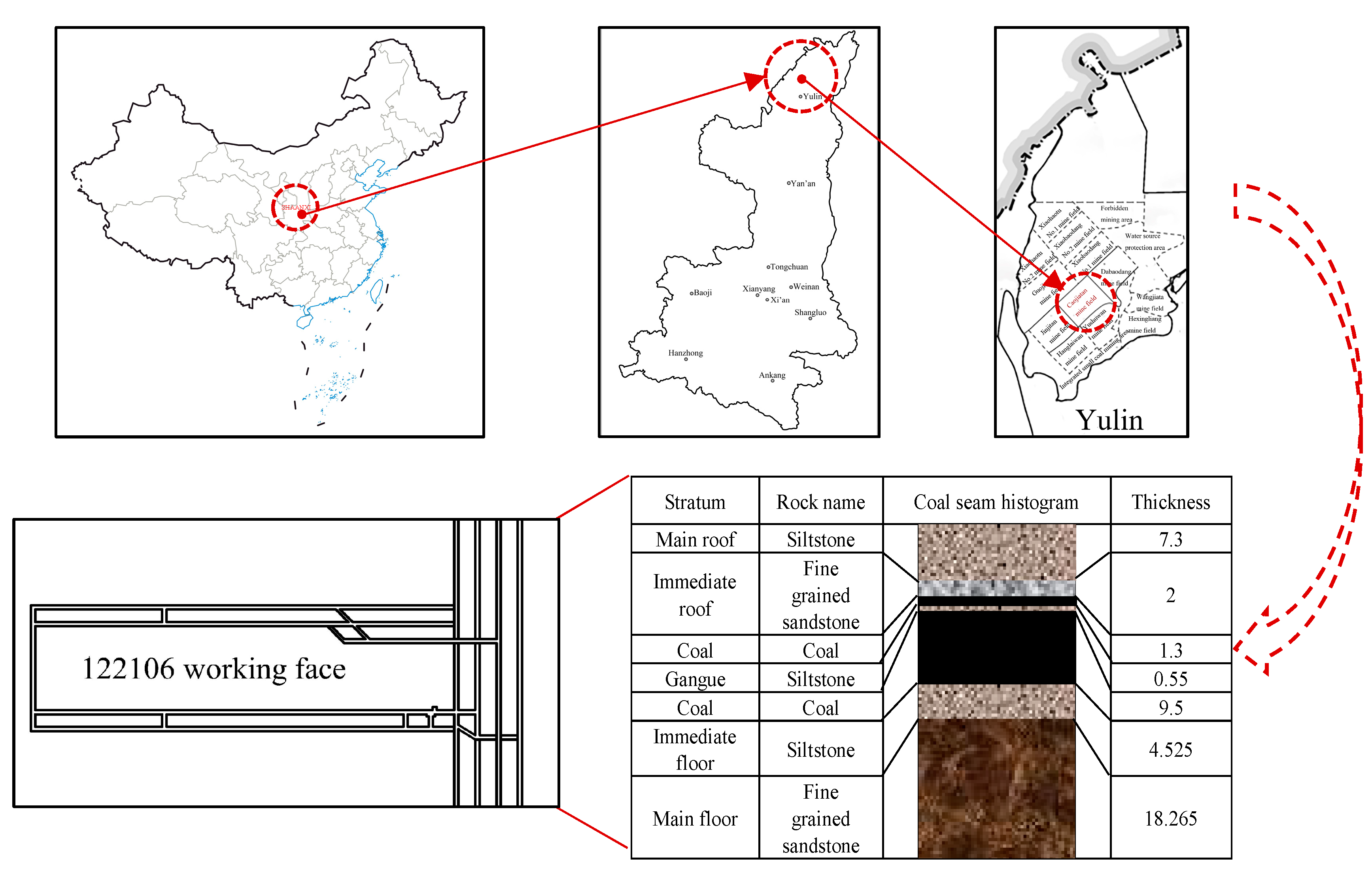
2. Project Overview
3. Model Establishment
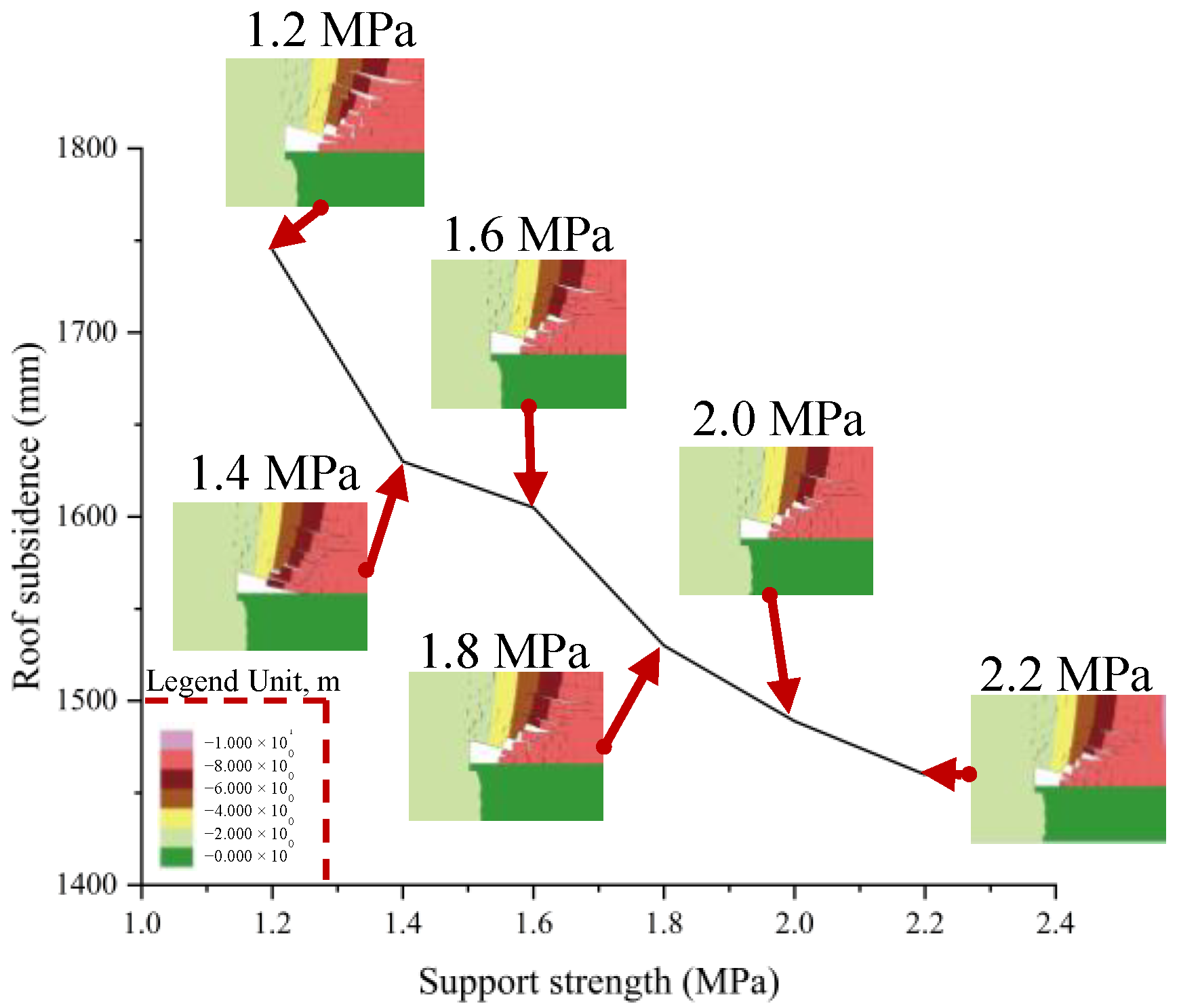
4. Study on Control of Roof Subsidence by Different Support Strengths
5. Study on the Control of Roof Subsidence and Surface Subsidence of Working Face under Different Filling Rates
5.1. Mechanical Model of Support and Surrounding Rock under Filling Conditions
5.2. Study on Control of Roof Subsidence and Surface Subsidence of Working Face under Different Filling Rates
6. Conclusions
- (1)
- With the increase of support strength, the maximum roof subsidence of the working face gradually decreases. When the support strength is 2.0 MPa, the roof subsidence of the working face is 1489 mm. When the support strength increases to 2.2 MPa, the roof subsidence is 1460 mm, and the reduction range of roof subsidence is very small. Therefore, we select the support strength of 2.0 MPa.
- (2)
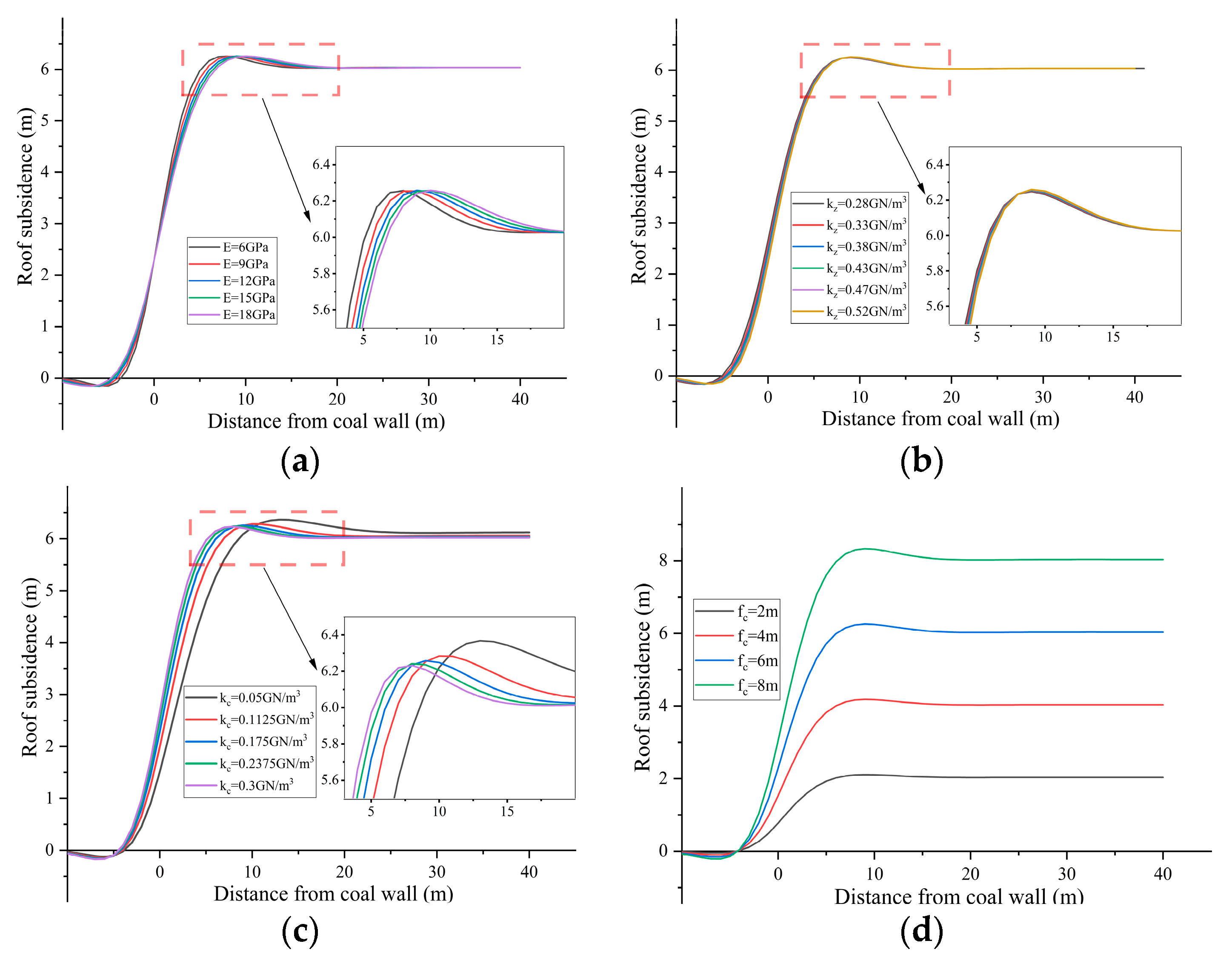
- By establishing the mechanical model of support and surrounding rock, the effects of direct roof elastic modulus , support elastic foundation coefficient , filling elastic foundation coefficient , and height of the gap between filling body and roof on roof subsidence are analyzed. The changes of and have little effect on the roof subsidence. When it is close to the working face, the greater the value of , the greater the roof subsidence. When it is far from the working face, the roof subsidence is almost only affected by the filling rate. When is 2 m, 4 m, 6 m, and 8 m, the maximum subsidence of the gob roof is 2.1 m, 4.2 m, 6.25 m, and 8.3 m, respectively. This indicates that with an increase of the thickness of the filling body, the deflection of the support control area will decrease, which achieves the purpose of roof safety control.
- (3)
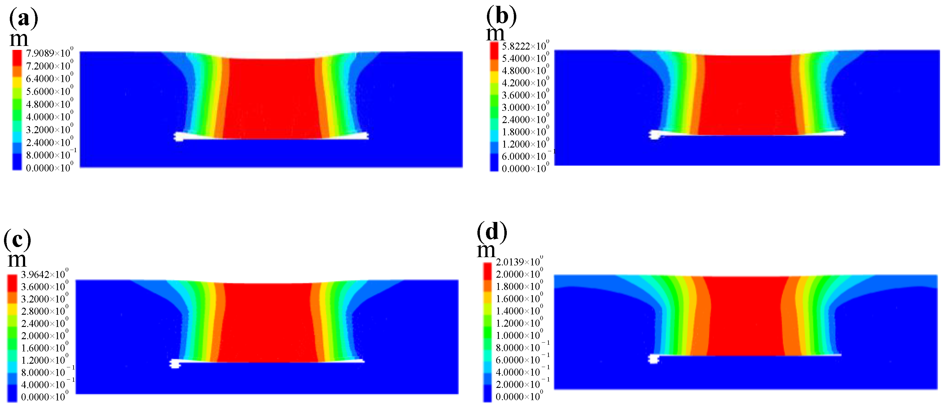
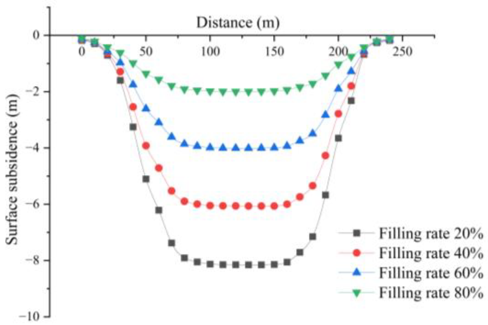
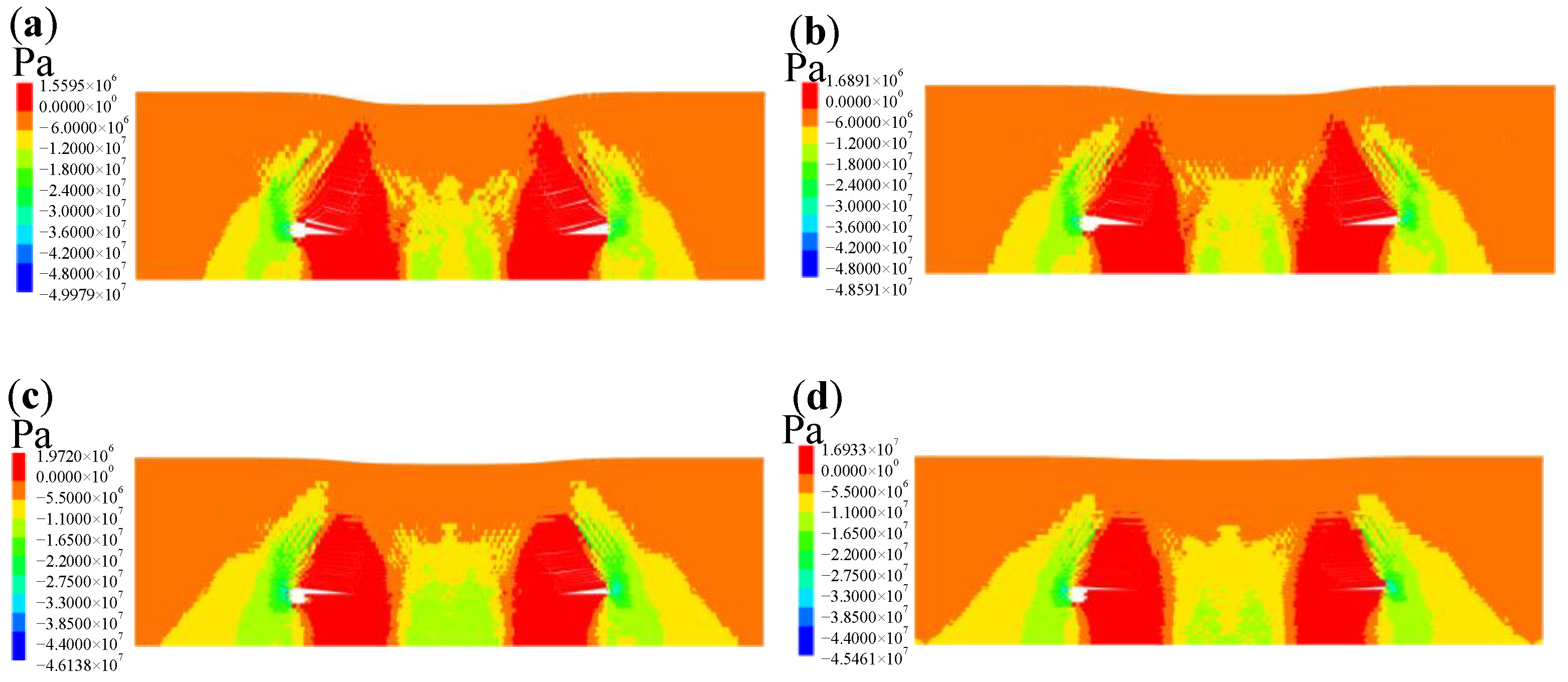
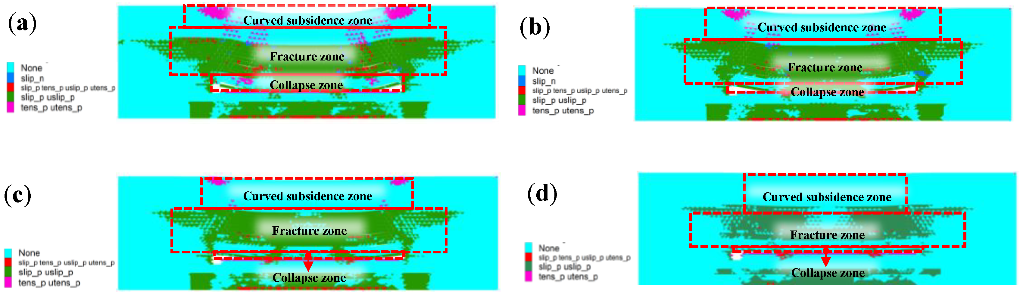
- When filling the goaf, the method adopted is immediate filling after model excavation. Through the analysis of displacement nephogram, stress nephogram and plastic zone diagram under different filling rates, and the monitoring of roof subsidence, determine the appropriate filling rate. Measuring points are positioned on the roof of the working face and upper boundary of the model to monitor the roof subsidence and surface subsidence of the model. By analyzing the surface subsidence curves under the conditions of different filling rates, it is found that the surface control effect is best when the filling rate is 80%.
Author Contributions
Funding
Conflicts of Interest
References
- Kong, D.Z.; Cheng, Z.B.; Zheng, S.S. Study on the failure mechanism and stability control measures in a large-cutting-height coal mining face with a deep-buried seam. Bull. Eng. Geol. Environ. 2019, 78, 6143–6157. [Google Scholar] [CrossRef]
- Le, T.D.; Zhang, C.G.; Oh, J.; Mitra, R.; Hebblewhite, B. A new cavability assessment for Longwall Top Coal Caving from discontinuum numerical analysis. Int. J. Rock Mech. Min. Sci. 2019, 115, 11–20. [Google Scholar] [CrossRef]
- Huang, P.; Ju, F.; Jessu, K.V.; Xiao, M.; Guo, S. Optimization and Practice of Support Working Resistance in Fully-Mechanized Top Coal Caving in Shallow Thick Seam. Energies 2017, 10, 1406. [Google Scholar] [CrossRef]
- Zhang, Q.Y.; Du, T. Research on and Application of Roof Management Technology in 8.8m Ultra-high Fully Mechanized Mining Face. In Proceedings of the Iop 5th International Conference on Materials Science, Energy Technology and Environmental Engineering (MSETEE), Electr Network, Shanghai, China, 7–9 August 2020; Iop Publishing Ltd.: Shanghai, China, 2020. [Google Scholar]
- Li, Z.L.; He, X.Q.; Dou, L.M.; Song, D.Z. Comparison of rockburst occurrence during extraction of thick coal seams using top-coal caving versus slicing mining methods. Can. Geotech. J. 2018, 55, 1433–1450. [Google Scholar] [CrossRef]
- Fu, J.H.; Wen, G.C.; Sun, H.T.; Yang, X.L. Study on the shear movement law of overlying strata by slice mining. Energy Sci. Eng. 2020, 8, 2335–2351. [Google Scholar] [CrossRef]
- Baryshnikov, V.D.; Gakhova, L.N. Stress-strain state of adjacent rock mass under slice mining of steeply dipping ore bodies. In Proceedings of the Conference on Geodynamics and Stress State of the Earth’s Interior (GSSEI), Russian Acad Sci, Siberian Branch, Inst Mining, Novosibirsk, Russia, 2–4 October 2017; Iop Publishing Ltd.: Novosibirsk, Russia, 2017. [Google Scholar]
- Li, Z.L.; He, X.Q.; Dou, L.M.; Song, D.Z.; Wang, G.F. Numerical investigation of load shedding and rockburst reduction effects of top-coal caving mining in thick coal seams. Int. J. Rock Mech. Min. Sci. 2018, 110, 266–278. [Google Scholar] [CrossRef]
- Song, Z.Y.; Konietzky, H.; Herbst, M. Drawing mechanism of fractured top coal in longwall top coal caving. Int. J. Rock Mech. Min. Sci. 2020, 130, 13. [Google Scholar] [CrossRef]
- Zhang, B.S.; Yang, Z.P.; Ji, C.X.; Guo, Z.F.; Li, H.Y. Research on the Influence of the Key Stratum Position on the Support Working Resistance during Large Mining Height Top-Coal Caving Mining. Adv. Civ. Eng. 2021, 2021, 6690280. [Google Scholar] [CrossRef]
- Yang, L.; Li, L.H.; Wei, W.J. Optimization of Caving Technology in an Extrathick Seam with Longwall Top Coal Caving Mining. Adv. Mater. Sci. Eng. 2021, 2021, 7725159. [Google Scholar] [CrossRef]
- Wen, Z.J.; Xing, E.R.; Shi, S.S.; Jiang, Y.J. Overlying strata structural modeling and support applicability analysis for large mining-height stopes. J. Loss Prev. Process Ind. 2019, 57, 94–100. [Google Scholar] [CrossRef]
- Yuan, H.H.; Shan, R.L.; Su, X.G. Deformation characteristics and stability control of a gateroad in fully mechanized mining with large mining height. Arab. J. Geosci. 2018, 11, 15. [Google Scholar] [CrossRef]
- Wu, F.F.; Yue, X.; Yang, J.X.; Du, B.J.; Zhang, J.; Lv, B. Model of Overlying Strata Structure in Large Mining Height Excavating Condition and Calculation of Support Working Resistance. Geofluids 2022, 2022, 5894735. [Google Scholar] [CrossRef]
- Cheng, F.; Chen, A.J.; Wu, D.; Tang, X.Y.; Su, C.H. Numerical Simulation of Cracking Failure and Weakening Law of Roadway Surrounding Rock under High Stress. Shock Vib. 2021, 2021, 7236077. [Google Scholar] [CrossRef]
- Gao, M.S.; He, Y.L.; Xu, D.; Yu, X. A New Theoretical Model of Rock Burst-Prone Roadway Support and Its Application. Geofluids 2021, 2021, 5549875. [Google Scholar] [CrossRef]
- Zhang, K.; Li, Y.X.; Feng, L.; Meng, X.J.; Zhong, D.H.; Huang, L.S. Roof deformation characteristics and experimental verification of advanced coupling support system supporting roadway. Energy Sci. Eng. 2022, 10, 2397–2419. [Google Scholar] [CrossRef]
- Sun, Y.T.; Li, G.C.; Zhang, J.F.; Yao, B.C.; Qian, D.Y.; Huang, J.D. Numerical Investigation on Time-Dependent Deformation in Roadway. Adv. Civ. Eng. 2021, 2021, 4280139. [Google Scholar] [CrossRef]
- Li, G.; Ma, F.S.; Guo, J.; Zhao, H.J.; Liu, G. Study on deformation failure mechanism and support technology of deep soft rock roadway. Eng. Geol. 2020, 264, 15. [Google Scholar] [CrossRef]
- Wang, Q.; Jiang, B.; Pan, R.; Li, S.C.; He, M.C.; Sun, H.B.; Qin, Q.; Yu, H.C.; Luan, Y.C. Failure mechanism of surrounding rock with high stress and confined concrete support system. Int. J. Rock Mech. Min. Sci. 2018, 102, 89–100. [Google Scholar] [CrossRef]
- Liu, W.T.; Pang, L.F.; Xu, B.C.; Sun, X. Study on overburden failure characteristics in deep thick loose seam and thick coal seam mining. Geomat. Nat. Hazards Risk 2020, 11, 632–653. [Google Scholar] [CrossRef]
- Wang, J.C.; Wang, Z.H. Systematic principles of surrounding rock control in longwall mining within thick coal seams. Int. J. Min. Sci. Technol. 2019, 29, 65–71. [Google Scholar] [CrossRef]
- Chen, Y.; Li, D.; Jiang, F.X.; Zhang, L.L.; Wang, C.W.; Zhu, S.T. Use of the Equivalent Mining Height Method for Understanding Overlying Strata Movement and Stress Distribution in an Isolated Coal Pillar. Shock Vib. 2020, 2020, 8820886. [Google Scholar] [CrossRef]
- Wang, H.W.; Wu, Y.P.; Liu, M.F.; Jiao, J.Q.; Luo, S.H. Roof-breaking mechanism and stress-evolution characteristics in partial backfill mining of steeply inclined seams. Geomat. Nat. Hazards Risk 2020, 11, 2006–2035. [Google Scholar] [CrossRef]
- Lin, H.; Yang, R.S.; Lu, B.; Li, Y.L.; Fang, S.Z.; Fan, Z.Y.; Li, Z.Z. Overlying strata movement law of continuous mining and continuous backfilling cemented-fill mining. Environ. Earth Sci. 2021, 80, 15. [Google Scholar] [CrossRef]
- Yu, H.X.; Li, S.; Wang, X.M. The Recent Progress China Has Made in the Backfill Mining Method, Part III: Practical Engineering Problems in Stope and Goaf Backfill. Minerals 2022, 12, 88. [Google Scholar] [CrossRef]
- Chang, Q.L.; Sun, Y.F.; Leng, Q.; Liu, Z.X.; Zhou, H.Q.; Sun, Y.T. Stability Analysis of Paste Filling Roof by Cut and Fill Mining. Sustainability 2021, 13, 10899. [Google Scholar] [CrossRef]
- Tan, L.H.; Zhou, Z.L.; Cai, X.; Rui, Y.C. Analysis of mechanical behaviour and fracture interaction of multi-hole rock mass with DIC measurement. Measurement 2022, 191, 18. [Google Scholar] [CrossRef]
- Sang, P.D. Research and Application of Green Filling Mining Technology for Short Wall Mining in Aging Mine. In Proceedings of the Iop 4th International Workshop on Renewable Energy and Development (IWRED), Electr Network, Sanya, China, 24–26 April 2020; Iop Publishing Ltd.: Sanya, China, 2020. [Google Scholar]
- Chen, D.D.; Wu, X.Y.; Xie, S.R.; Sun, Y.D.; Zhang, Q.; Wang, E.; Sun, Y.H.; Wang, L.; Li, H.; Jiang, Z.S.; et al. Study on the Thin Plate Model with Elastic Foundation Boundary of Overlying Strata for Backfill Mining. Math. Probl. Eng. 2020, 2020, 8906091. [Google Scholar] [CrossRef]
- Zhu, X.J.; Guo, G.L.; Liu, H.; Yang, X.Y. Surface subsidence prediction method of backfill-strip mining in coal mining. Bull. Eng. Geol. Environ. 2019, 78, 6235–6248. [Google Scholar] [CrossRef]
- Sun, Y.T.; Bi, R.Y.; Sun, J.B.; Zhang, J.F.; Taherdangkoo, R.; Huang, J.D.; Li, G.C. Stability of roadway along hard roof goaf by stress relief technique in deep mines: A theoretical, numerical and field study. Geomech. Geophys. Geo-Energy Geo-Resour. 2022, 8, 16. [Google Scholar] [CrossRef]
- Cai, W.Y.; Chang, Z.C.; Zhang, D.S.; Wang, X.F.; Cao, W.H.; Zhou, Y.Z. Roof filling control technology and application to mine roadway damage in small pit goaf. Int. J. Min. Sci. Technol. 2019, 29, 477–482. [Google Scholar] [CrossRef]
- Sun, Y.T.; Bi, R.Y.; Chang, Q.L.; Taherdangkoo, R.; Zhang, J.F.; Sun, J.B.; Huang, J.D.; Li, G.C. Stability Analysis of Roadway Groups under Multi-Mining Disturbances. Appl. Sci. 2021, 11, 7953. [Google Scholar] [CrossRef]
- Li, G.C.; Sun, Y.T.; Qi, C.C. Machine learning-based constitutive models for cement-grouted coal specimens under shearing. Int. J. Min. Sci. Technol. 2021, 31, 813–823. [Google Scholar] [CrossRef]


| Number | Rock Lithology | Thickness/m | Density/kg∙m−3 | Bulk Modu-lus/GPa | Shear Mod-ulus/GPa | Friction Angle/° | Cohesion/MPa | Tensile Strength/MPa |
|---|---|---|---|---|---|---|---|---|
| 1 | Loess | 34 | 1960 | 0.25 | 0.09 | 25 | 5.5 | 0.35 |
| 2 | Medium-grained sandstone | 24 | 2987 | 23.4 | 13 | 40 | 3.6 | 4.07 |
| 3 | Fine-grained sandstone | 12 | 2610 | 2.23 | 1.67 | 38 | 3 | 3.15 |
| 4 | Siltstone | 8 | 2558 | 6.32 | 3.61 | 33 | 4.7 | 3.07 |
| 5 | Fine-grained sandstone | 2 | 2610 | 2.23 | 1.67 | 38 | 3 | 3.15 |
| 6 | Siltstone | 3 | 2603 | 7 | 4 | 43 | 4.3 | 6.99 |
| 7 | Filling body | 2~8 | 1900 | 5.5 | 2.1 | 36 | 0.4 | 0.5 |
| 8 | Coal | 10 | 1445 | 7.1 | 4.9 | 22 | 1.44 | 2.4 |
| 9 | Siltstone | 9 | 2558 | 6.32 | 3.61 | 33 | 4.7 | 3.07 |
| 10 | Fine-grained sandstone | 18 | 2690 | 2.23 | 16.7 | 32 | 2.8 | 3.17 |
| Support strength/MPa | 1.2 | 1.4 | 1.6 | 1.8 | 2.0 | 2.2 |
| Roof subsidence/mm | 1745 | 1630 | 1605 | 1530 | 1489 | 1460 |
| Average Volume Force of Overburden γ/(kN/m3) | Elastic Foundation Coefficient of Coal km/(GN/m3) | Elastic Foundation Coefficient of Hydraulic Support kz/(GN/m3) | Elastic Foundation Coefficient of Backfill kc/(GN/m3) | Elastic Modulus of Direct Roof Rock Beam E/GPa | Height of Gap between Filling Body and Roof fc/m |
|---|---|---|---|---|---|
| 25 | 0.2~0.6 | 0.28~0.52 | 0.05~0.3 | 5~20 | 2~10 |
Publisher’s Note: MDPI stays neutral with regard to jurisdictional claims in published maps and institutional affiliations. |
© 2022 by the authors. Licensee MDPI, Basel, Switzerland. This article is an open access article distributed under the terms and conditions of the Creative Commons Attribution (CC BY) license (https://creativecommons.org/licenses/by/4.0/).
Share and Cite
Wo, X.; Li, G.; Li, J.; Yang, S.; Lu, Z.; Hao, H.; Sun, Y. The Roof Safety under Large Mining Height Working Face: A Numerical and Theoretical Study. Minerals 2022, 12, 1217. https://doi.org/10.3390/min12101217
Wo X, Li G, Li J, Yang S, Lu Z, Hao H, Sun Y. The Roof Safety under Large Mining Height Working Face: A Numerical and Theoretical Study. Minerals. 2022; 12(10):1217. https://doi.org/10.3390/min12101217
Chicago/Turabian StyleWo, Xiaofang, Guichen Li, Jinghua Li, Sen Yang, Zhongcheng Lu, Haoran Hao, and Yuantian Sun. 2022. "The Roof Safety under Large Mining Height Working Face: A Numerical and Theoretical Study" Minerals 12, no. 10: 1217. https://doi.org/10.3390/min12101217