Article

The Recent Progress China Has Made in the Backfill Mining Method, Part III: Practical Engineering Problems in Stope and Goaf Backfill

School of Resources and Safety Engineering, Central South University, Changsha 410083, China
*
Author to whom correspondence should be addressed.
Minerals 2022, 12(1), 88; https://doi.org/10.3390/min12010088
Submission received: 15 December 2021 / Revised: 7 January 2022 / Accepted: 9 January 2022 / Published: 13 January 2022
(This article belongs to the Special Issue Backfilling Materials for Underground Mining, Volume II)

Abstract

:
With the continuous innovation and development of science and technology, the mining industry has also benefited greatly and improved over time, especially in the field of backfill mining. Mining researchers are increasingly working on cutting-edge technologies, such as applying artificial intelligence to mining production. However, in addition, some problems in the actual engineering are worth people’s attention, and especially in China, such a big mining country, the actual engineering faces many problems. In recent years, Chinese mining researchers have conducted a lot of studies on practical engineering problems in the stope and goaf of backfill mining method in China, among which the three most important points are (1) Calculation problems of backfill slurry transportation; (2) Reliability analysis of backfill pipeline system; (3) Stope backfill process and technology. Therefore, this final part (Part III) will launch the research progress of China’s practical engineering problems from the above two points. Finally, we claim that Part III serves just as a guide to starting a conversation, and hope that many more experts and scholars will be interested and engage in the research of this field.

1. Introduction

With the continuous development of mining technology, mining efficiency is greatly improved, mining safety is also improved, mining industry prosperously develops, and mining industry prospects are bright. China, as a big mining country, although the development of mining technology started slowly, has made rapid progress. In the recent 5 years, more and more mining researchers in China have begun to engage in the research of intelligent mines: Yu et al. [1,2,3] have been trying to build an intelligent integrated underground ventilation and transportation system since the end of 2020; Li [4,5] also tried to use a communication-based train control system (CBTC) to realize unmanned rail transportation in underground mines; and Zhao [6] tried to use smart scrapers (LHD) as basic equipment in underground mines. Intelligent mines in China develop rapidly, and the development of intelligent mines also drives the development and progress of backfill mining method. For example, Qi Chong et al. [7,8] applied artificial intelligence to the backfill mining method (predicting the strength of the filling slurry).
Since the 21st century, China has focused on the development of the backfill (filling) mining method, in order to improve the efficiency and safety of mining production. For China at present, the biggest problems are from the actual engineering: Because China is a mining power, there are many mines in China, the development of each mine is very different, and the engineering and geological situation is complicated. Therefore, the study of stope backfill in practical engineering is particularly important.
In China, mining researchers define the whole backfill (or filling) process in stope (or goaf) as follows [9]: After the qualified filling slurry is prepared on the surface, it is generally entered into the roadway of the main and auxiliary production system by the surface or filling borehole, and then transferred to the filling patio at the top of the stope by a hose for filling of the goaf. Stope filling is not only the end of the whole filling system, but also the fault node of the whole filling system, which is most prone to pipe wear, cavitation, pipe blocking, pipe bursting, stratification and segregation, and slurry leakage. Therefore, the study of stope filling technology is of great significance to ensure the stability of the filling system and improve the quality and effect of filling.
It can be seen that in practical engineering, there are often many problems in the filling process. As China is a mining power with many mines in different engineering situations, many Chinese researchers have made a lot of effort and research on the practical problems in stope filling [10,11].
Thus, as the last part of our series (Part I introduced the research on backfill pipeline transportation in China, Part II introduced the backfill systems and examples in China), this paper, Part III, still as a medium to lead readers to China’s mining industry, focusing on the practical engineering problems, mainly introduces three aspects:
(1)
Calculation problems of backfill slurry transportation.
(2)
Reliability analysis of backfill pipeline system.
(3)
Stope backfill process and technology.

2. Calculation Problems of Backfill Slurry Transportation

2.1. Interference Settlement of Tailings Particles

In the process of pipeline transportation of filling slurry, tailings particles are free to settle under the action of gravity in still water, and the velocity of uniform particle subsidence is called settlement velocity [12]. The sedimentation velocity directly reflects the difficulty of hydraulic transportation of solid particles: the higher the sedimentation velocity is, the more difficult the particles are to suspend, and the more difficult the hydraulic transportation is. The settling velocity (vg) of fine particle size can be expressed by simplified Stokes formula, ignoring the effect of medium viscosity on settling velocity:
V g = 5450 d c p 2 ( γ g 1 )
where dcp is the diameter of solid particles; γg is the density of solid particles.
The surface of the whole tailings is irregular, and it is easy to rotate and flow around due to uneven force in the settlement of still water, which leads to the increase of settlement resistance and decrease of settlement velocity. In the process of pipeline transportation, due to mechanical collision and friction between solid particles and between particles and pipe wall, the resistance of solid particles sinking increases and the settlement velocity decreases. The higher the slurry concentration is, the finer the particle size of the solid particle is, the more irregular the shape is, the coarser the surface is, the greater the resistance of the fluid to the particle is, the lower the settlement velocity is, and vice versa. Interference settlement velocity of nonspherical particles (vgg) can be expressed as
v g g = C s v g ( 1 C v ) n
where Cs is the correction coefficient; Cv is slurry volume concentration; n is the interference index.
As can be seen from the above Equation (2), the smaller the diameter of the whole tailings particles is, the smaller the settlement velocity in still water is, and the rotation and flow around the particles are more frequent, leading to the increase of the settlement resistance of the whole tailings particles and the decrease of the interference settlement velocity. The particle size of the whole tailings in many mines is very fine, the interference settlement velocity is low, the aggregate particles are easy to suspend, and the slurry pipeline transportation performance is better [13].

2.2. Settlement and Plugging of Coarse Tailings

It is of positive significance for the smooth transportation and the normal operation of the system whether the ultrafine total tailing aggregate particles with constant velocity can be suspended uniformly and flow stably in the pipeline transportation process [14]. In the process of solid–liquid two-phase fluid pipeline transportation, eddy scour of slurry caused by uneven velocity distribution and fluid flow around slurry are only auxiliary factors to enhance the irregular movement of aggregate particles, and the pulsation velocity of the turbulent flow is the decisive factor of solid particles suspension. The vertical component of turbulent velocity Sv is greater than the settling velocity (vgg) of solid particles, and the aggregate particles can be suspended uniformly and stably. If the vertical pulsation velocity component is less than the settling velocity of solid particles, pipe blockage may occur [15]. The vertical pulsation velocity component Sv is calculated by the following formula:
S v = 0.13 v ( 2 g D i k C u , v V 2 ) 1 / 2 [ 1 + 1.72 ( y r ) 1.8 ]
where g represents gravity; v is the conveying speed of slurry; k is the test constant, and its value is 1.5–2; Cu,v is the relationship between horizontal velocity component and vertical velocity component, which is 0.18; y is the distance between solid particles and the center of the pipe; r is the radius of the conveying pipeline; we take y = r; i as the hydraulic gradient of slurry, which is calculated by Jinchuan formula as follows:
i = λ v 2 2 g D { 1 + 108 C v 3.96 [ g D ( γ j 1 ) v 2 C x ] 1.12 }
where g represents gravity; γj is the slurry weight, unit: t·m−3; Cv is slurry volume concentration; D is the pipe inner diameter, unit: m; λ is the friction resistance coefficient of clean water, which can be calculated by the following formula:
λ = K 1 K 2 ( 2 l g D 0.00024 + 1.74 ) 2
where K1 is the laying coefficient of pipeline, generally K1 = 1.1; K2 is the pipe connection quality coefficient, generally K2 = 1.1.
The calculation formula of settlement resistance coefficient Cx is as follows:
C x = 1308 ( γ j 1 ) d c p ω 2
where dcp is the average particle size of filling material, unit: cm; ω is the average settling velocity of particles, unit: cm·s−1.

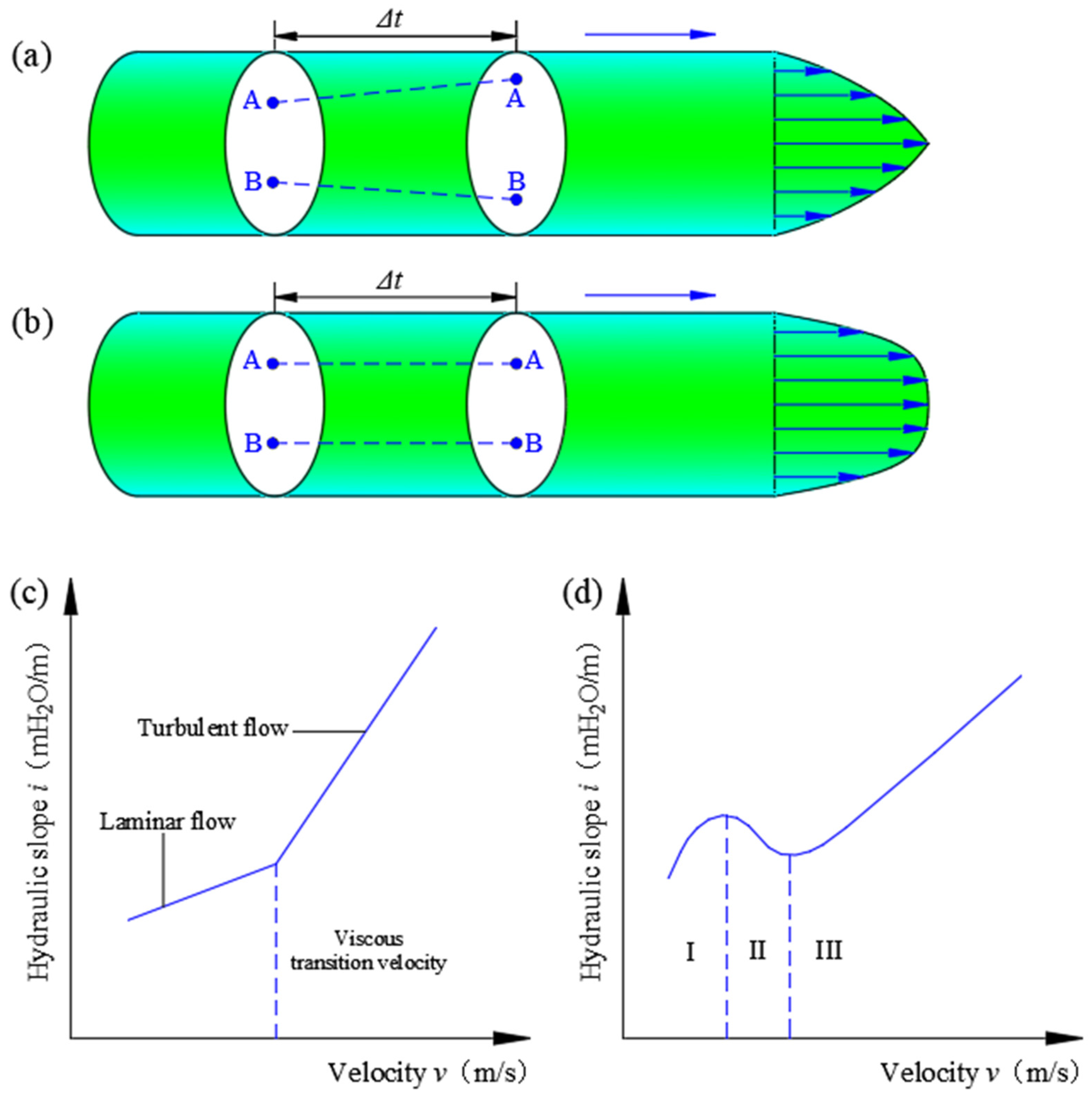
2.3. Transport Flow Pattern of Backfill Slurry

As the filling slurry concentration increases from low to high, the viscosity increases correspondingly, and has a tendency to prevent the settlement of solid particles. When the filling concentration passes a critical point, the slurry transport characteristics will change from two-phase flow to structural flow. Unlike two-phase flow, there is no measurable concentration gradient in the slurry along the vertical direction of the pipe. After flowing, the material moves as a whole similar to a solid, flowing in the pipe in the form of a “plunger” separated from the pipe wall by a very thin layer of lubrication. The velocity distribution of structural flow on the cross section of the pipeline is relatively uniform, and there is no relative movement between particles. After Δt time (as shown in Figure 1a,b), the relative position of point A and point B of any cross section remains unchanged, showing a nonsedimentation state [16].
As shown in Figure 1c, the relationship between the resistance and flow velocity of the filling body with solid–liquid two-phase flow is similar to that of clean water and clay. At the initial stage of increasing flow velocity, the filling body shows the characteristics of laminar flow, and its resistance along the flow increases with the increase of slurry flow velocity. However, with the continuous increase of flow velocity, the degree of vortex and turbulence intensity resulting from the interaction between slurry flow and the side wall will increase, thus showing the characteristics of turbulent flow, and the resulting energy loss will increase correspondingly, thus making the resistance loss increase. As shown in Figure 1d, the relationship between resistance and flow velocity of backfill with structural flow pattern includes three stages: stage I is the stage where initial resistance increases with the increase of slurry flow velocity; in stage II, the thixotropic effect occurs under the shear action of the pipe wall, which reduces the viscosity of the slurry, and the resistance decreases with the increase of the flow rate of the slurry. In stage III, the shear thixotropic effect of slurry reaches equilibrium state, the viscosity of slurry no longer decreases, and the resistance along the process begins to increase with the increase of slurry flow rate [17].

2.4. Selection of Filling Industrial Pump

The pumping pressure is calculated according to the pumping pressure formula for conveying paste and fine stone concrete [18,19]:
P b = P 0 + ( 1 + k ) L i m + γ j g Δ H / 100
where P0 represents the starting pressure of the pump, unit: MPa, P0 = 2 MPa if there is no measured data; L represents total pipeline length, m, including horizontal section and vertical short; k represents local resistance coefficient, 0.1~0.3; im represents hydraulic slope, calculated according to empirical formula; Δ H represents the height difference of the transportation starting point.
When selecting equipment according to conveying capacity Qc, the maximum theoretical displacement of the pump should be slightly greater than actual conveying capacity Qs, that is,
Q c = ( 1.05   ~ 1.1 ) Q s
According to the above calculation results, a filling industrial pump was selected for filling slurry pumping and filling. At the same time, a spare filling pump can be added during the maintenance of pumping equipment or in the case of damage [20].

2.5. Selection of Filling Pipeline

Filling pipe wall thickness δ is calculated as follows:
δ = P D 1 2 [ σ ] + K
where P is the maximum pressure of the pipeline; σ represents allowable tensile stress of steel, σ = 80 MPa; K represents wear corrosion, generally K = 3 mm.
Generally, the calculation results are rounded, seamless steel pipes are selected, and quick joints are used to connect horizontal pipes [18,21].

3. Reliability Analysis of Backfill Pipeline System

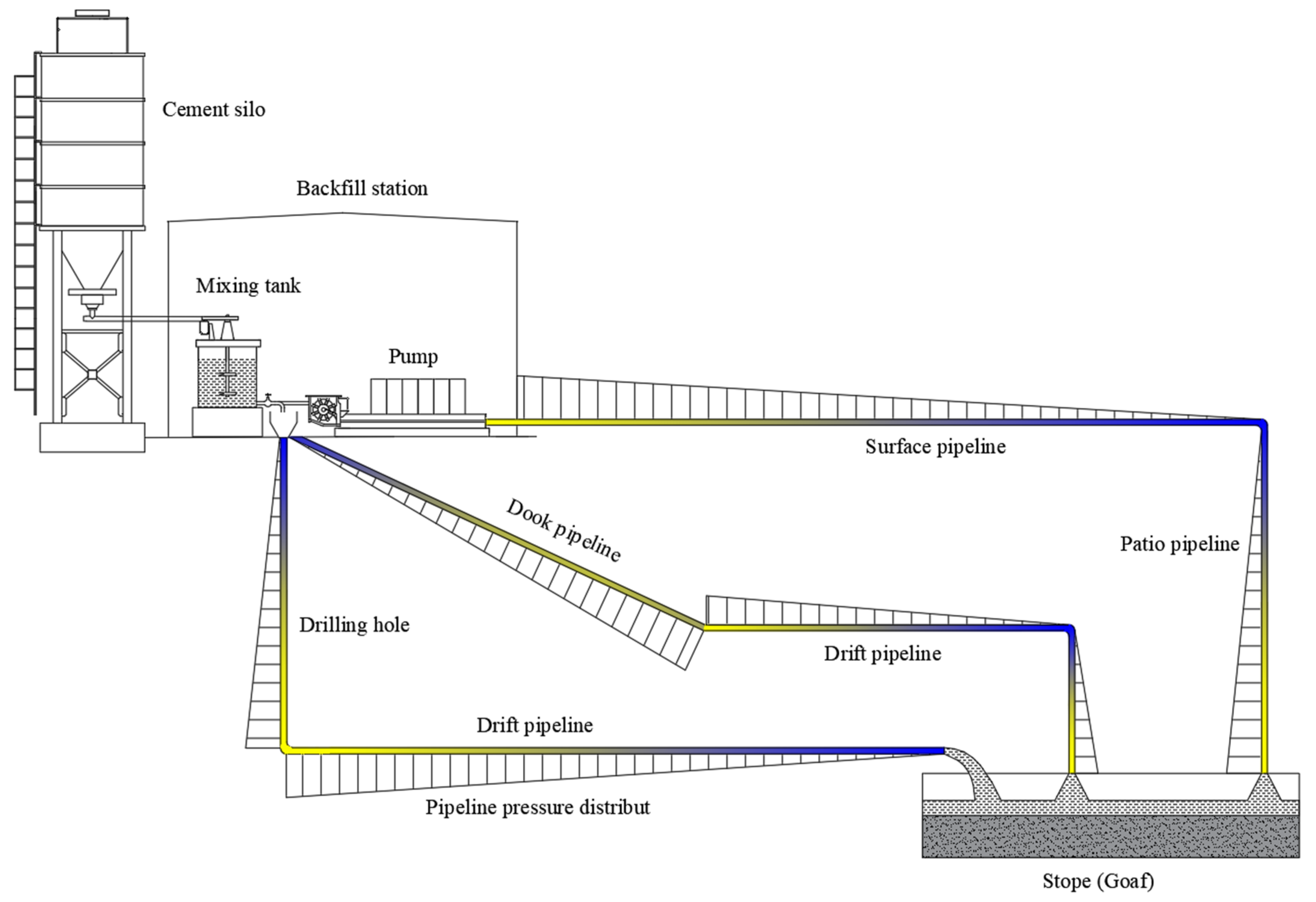
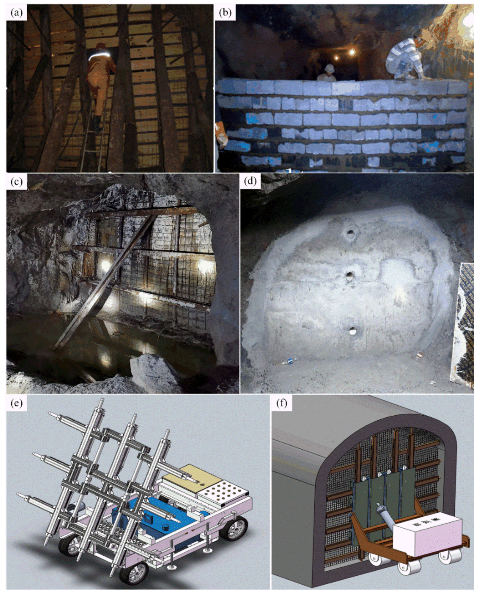
3.1. Filling Pipe Layout

After the qualified filling slurry is prepared on the surface, it is generally entered into the roadway of the main and auxiliary production system by the surface or filling borehole, and then the hose is transferred to the filling patio at the top of the mined-out area to fill the mined-out area. Considering that during the operation of the filling system, it is necessary to inspect the filling pipeline and replace it in time when the filling pipeline is seriously worn, the filling pipeline should not be arranged in the shaft, which will lead to inconvenient maintenance. It is not allowed to be placed in the main hoisting shaft, because pipe blocking and pipe bursting will affect the hoisting system. It is forbidden to arrange in the return air shaft, which will affect the safety of inspection workers [22].
As shown in Figure 2, according to the main production system roadway experienced by filling pipeline layout, the filling pipeline layout mainly includes the following three schemes.

3.1.1. Borehole and Roadway Layout

Borehole and roadway layout is the simplest and most commonly used filling pipe layout in mines.
Qualified filling slurry is prepared after high-speed activation and stirring in the mixing tank in the surface filling station, which can be self-flowing or pumped into the filling hole below the mixing tank. The filling contact drift is constructed in the position close to the filling station, and the main production roadway is connected with the filling borehole. Then, the filling slurry can enter the main production drift through the filling borehole from the surface filling preparation station, and then the hose is transferred to the filling patio at the top of the mined-out area to fill the mined-out area. If the dead weight of the vertical slurry in the filling drilling section can be the resistance of the whole pipeline transportation, the method of self-flow transportation can be adopted. On the contrary, it is necessary to increase the filling pump to provide additional conveying power to transport the filling slurry to the goaf.

3.1.2. Ground Surface and Borehole Layout

Unlike borehole and roadway layout, ground surface and borehole layout are used to lay filling pipes on the surface above the goaf to be filled. This kind of filling layout is suitable for an ore body with relatively concentrated distribution, surface topography, and simple, easy to land, expropriation laying pipelines.
As land acquisition is often required to lay filling pipes on the ground surface, and environmental accidents are easily caused when pipes are blocked and burst, the ground surface and borehole layout scheme is seldom applied in domestic mines. At the same time, the filling pump must be configured to provide additional power for the transportation along the surface before the filling slurry enters the drilling hole (borehole). Therefore, the whole process artware transportation cannot be realized, which is another main reason why the application of the ground surface and borehole layout is relatively rare.

3.1.3. Adit and Inclined Shaft Layout Scheme

In many small and medium-sized mines in China, quite a few of them adopt adit and inclined shaft joint development. In order to make full use of the surface topography and reduce the engineering amount of underground filling contact roadway, the pipeline layout scheme that directly lays filling pipes in adits and inclined shafts and directly fills the goaf along the main underground roadway will be selected. Similarly, as the filling slurry must be equipped with a filling pump to provide additional conveying power in the adit conveying section before entering the hole, the scheme cannot realize the whole flow artesian conveying.

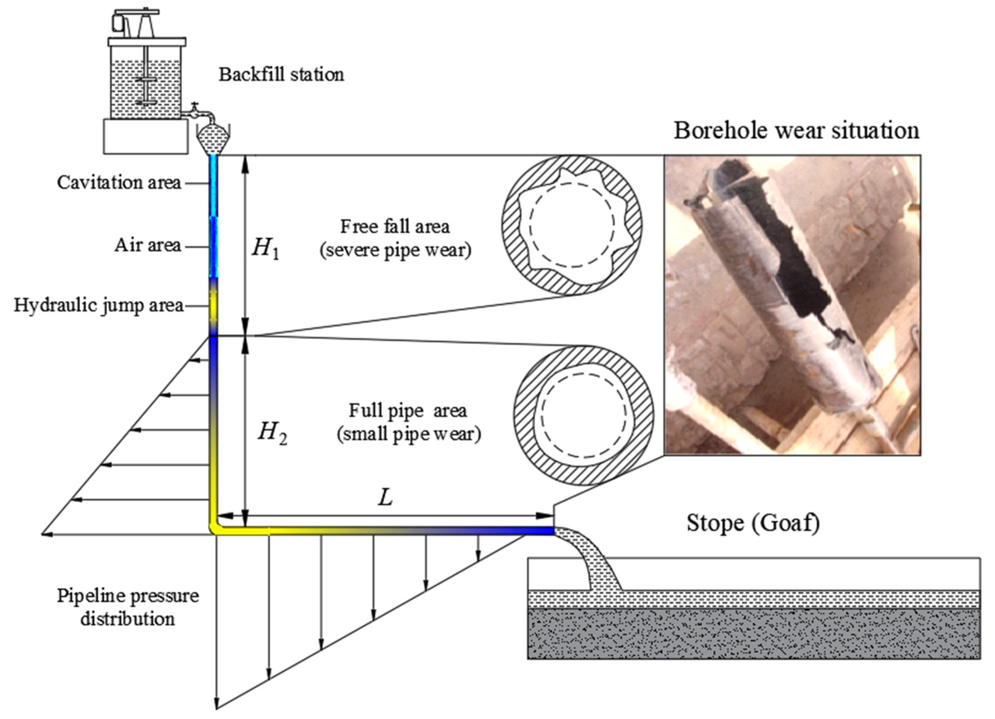
3.2. Artesian Transportation and Pipe Wear

Pipeline transportation of filling slurry has many advantages such as good continuity, large conveying capacity, low energy consumption, and high degree of automation. Most mines are connected with the main shaft and roadway through vertical filling drilling in filling station, and a small number of mines are connected directly with the main development shaft and roadway by laying filling pipes on the surface. According to the different filling power, the transportation mode of cemented slurry can be divided into two forms: pipe self-flow (gravity) backfill transportation and pressure pumping.
Gravity filling is to transport the filling slurry to the filling site by using the slurry column pressure in the vertical pipe to overcome the resistance of the horizontal pipe. This conveying method has simple process, no artificial power, and less investment. However, because its power is slurry column pressure, it has higher requirements for filling doubling line. According to the experience of filling mines at home and abroad, the general requirement of pipe self-flow transportation is that the geometric filling multiples of pipeline system are less than 5–6. Geometric filling pipeline doubling N is calculated according to the following formula:
N =   L   H
where ΣH represents the height difference between the starting and ending point of the pipeline; ΣL represents the total length of the pipe, including the converted length of pipe fittings such as elbows and joints.
In the case of insufficient height difference and too-large filling doubling line, the filling industrial pump is used to provide extra power and pressurize the filling slurry to the filling site. This transportation mode is not limited by the filling doubling line, has a wide range of use, and can transport high concentration of filling slurry, which can significantly improve the filling quality, reduce the filling cost, shorten the curing time of the filling body, and reduce the dehydration rate of the filling body. However, it requires the filling pumping equipment and requires a large investment.
As shown in Figure 3, most mines carry out stope filling by constructing vertical filling boreholes near the surface of filling stations to connect with the main underground wells and lanes and adopt the method of self-flow filling. In the vertical borehole, the filling slurry first moves in free fall, forming cavitation zone, air zone, and water jump zone successively. In the cavitation zone, the liquid flow will vaporize, undergo cavitation, or form a cavity, or the formation of discontinuous flow; the air zone is a mixture of water vapor and air. The fluid breaks away from the pipe boundary and moves faster and faster under gravity. The water jump zone is the phenomenon of rolling and strong vibration in the pipe when the free fall velocity of the slurry reaches the maximum. As the filling slurry conveying speed and pressure are large, it is inevitable to produce normal and oblique impact force on the inner wall of the conveying pipe, resulting in wall wear. Filling of drill wear is a more serious reason, in addition to the borehole construction quality, casing material, composition, filling pulp filling factors such as working parameters, free fall area because of the filling pulp in a state of dissatisfaction pipe conveying, high-speed flow of the filling pulp causing strong erosion, cavitation, and tumbling, making the pipeline of wear very serious. The pipe in the full pipe conveying area is in a relatively stable flow state, the wear of the inner wall of the pipe is more uniform, and the wear rate is lower [23].

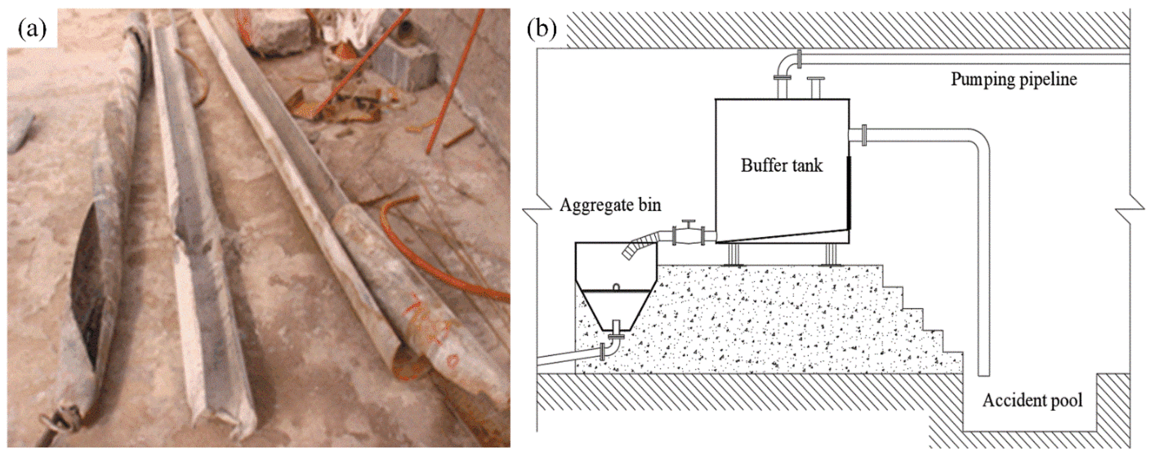
3.3. Pumping System and Pressure Relief Device

In the case of insufficient height difference and too-large filling doubling line, the filling industrial pump is used to provide extra power and pressurize the filling slurry to the filling site. This conveying method can be used in a wide range without the restriction of filling doubling line. For the surface pipeline + patio pipeline pressurized pumping scheme, as the filling slurry is transported along the surface before entering the borehole (pumping velocity is generally about 1.5 m/s), it must be equipped with a filling pump to provide additional conveying power. However, after entering the patio in the second half, the slurry can rely on its own gravitational potential energy to overcome the resistance of pipeline transportation and self-flow into the goaf (gravity self-flow velocity up to 3 m/s or more). If you still use the common to the closed pumping transportation mode, then entering the patio will cause filling pulp to accelerate under the influence of the potential energy in itself, and then by the low-speed full pipe flow to accelerate the full flow, flow cavitation, and negative pressure. The phenomena such as cavitation and erosion will not only dramatically accelerate the abrasion rate of the pipeline, it will also cause problems such as vacuum water strike and pipeline strong vibration, which will endanger the safety and stability of the whole filling pipeline transportation [18,24].
As shown in Figure 4, through setting between pump and the pipeline pressure relief devices, all the closed pumping pipe will be opened and perform relatively independent pumping, and their two casings can effectively solve the closed pipeline system for pumping high-energy consumption, flow cavitation phenomenon, severe cavitation and vibration, local area wear speed and poor stability of the system as a whole.

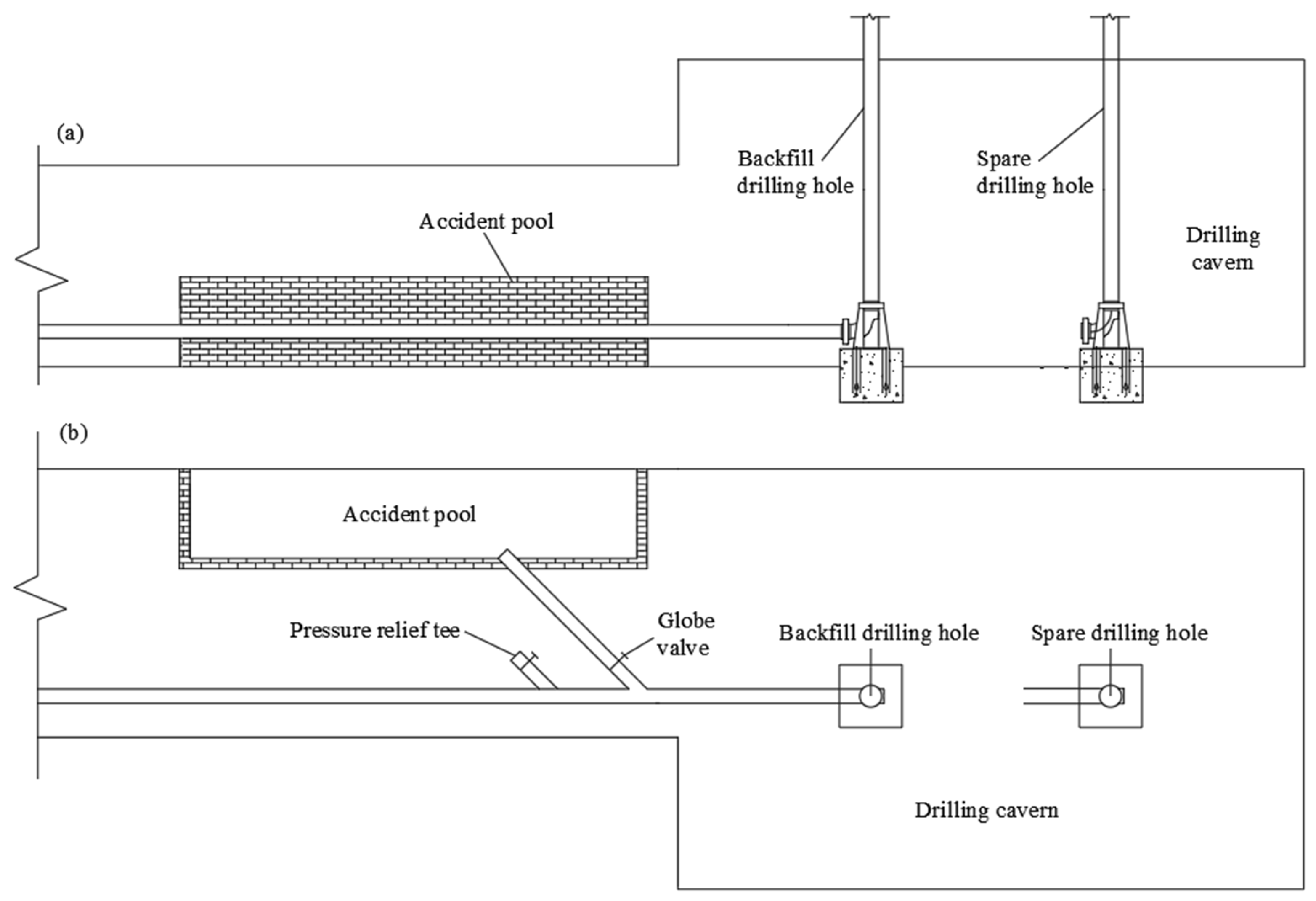
3.4. Emergency Treatment of Underground Filling Pipeline Accident

In order to reduce the consumption of filling drainage water and pipe-washing water, reduce the drainage pressure of underground filling slurry, and provide treatment measures for pipe blocking, a three-way pipe is added at the connection between vertical pipe and horizontal pipe to introduce high-pressure wind and high-pressure water during the installation and layout of underground filling pipe. Under normal circumstances, the pipeline layout in the horizontal roadway should have a certain downward slope, not reverse conveying filling. Bends and joints should be reduced as much as possible to avoid local resistance increase and pipe blocking accidents caused by slowing flow rate. Straight pipe connections should be avoided, as well as the existence of sharp corners [25].
As shown in Figure 5, as the connection between vertical pipe and horizontal pipe is an easily blocked pipe, an accident treatment valve and an accident pool should be set up. At the same time, the fluctuation of the pipeline should be strictly controlled to reduce the wear and blockage of the pipeline and prolong the service life of the pipeline [26].

4. Stope Backfill Process and Technology

4.1. Backfill Retaining Wall Construction

One of the key processes of goaf filling is to construct a closed channel between the goaf to be filled and the outside world. The filling retaining wall is required not only to bear the pressure of the filling slurry in the goaf, but also to have good defiltration performance. Compared with the horizontal slicing filling, the goaf with subsequent filling has higher requirements for the construction of the filling retaining wall because of the large volume and high height of the primary filling, and the manual filling cannot be carried out in the goaf. According to the different construction materials of filling retaining walls, filling retaining walls commonly used in mines at present include wooden filling retaining wall, brick retaining wall, steel mesh flexible filling retaining wall, concrete retaining wall, hydraulic filling retaining wall, etc. (as shown in Figure 6) [27].
Steel mesh flexible filling retaining wall is the most commonly used construction method for filling retaining walls at present, and mainly adopts a three-layer structure of round steel or I-steel, steel wire mesh, and double-layer geotextile. I-steel is welded longitudinally and longitudinally with round steel to form a well-shaped structure, and round steel is buried through the flanged geotextile into the surrounding rock mass in advance of the hole and sealed with cement mortar, as the core bearing structure of the whole filling retaining wall. Steel wire mesh and geotextile is the secondary bearing structure, and also has the role of defiltration water, geotextile double layer, sandwiched in the middle of two layers of wire mesh, the geotextile flanging, through the round steel through the anchor, the use of shotcrete machine shotcrete fixed in the roadway, and the outside of the filling retaining wall with wood diagonal support.
The traditional backfill retaining wall has many problems, such as complicated construction process, high labor-intensity of workers, limited bearing capacity of retaining wall, easy leakage of slurry, and large consumption of disposable consumables such as wood, brick, and concrete structure and steel wire mesh, low recovery and utilization rate, resulting in low construction efficiency, high comprehensive cost and difficulty in recycling. At present, the new type of hydraulic filling retaining wall, including walking devices, driving devices and stent, the hydraulic control system, automatic telescopic build retaining wall, has high efficiency, high speed, and low labor-intensity of workers, The telescopic bracket with four-wheel traveling gear facilitates transport within stope and is recycled repeatedly, and then reduces the comprehensive construction cost of the filling of the retaining wall greatly. In addition, the expansion bracket, a new filling retaining wall construction method, has a large drainage area and fast dehydration of the filling slurry, which is conducive to the rapid solidification of the filling slurry and prevents the pollution of the underground environment caused by the leakage of the filling slurry.

4.2. Stope Drainage Water

As shown in Figure 7, the drainage modes of stope mainly include geotextile drainage, drainage hole drainage, drainage well drainage, drainage rope drainage, etc. The traditional stope drainage technology is to add a filter cloth in the filling retaining wall at the bottom of the stope, so that the water from the filling slurry can permeate out naturally from the filling retaining wall. However, due to that the filling of the retaining wall area is smaller, often with filling pulp, the filling contact area of the retaining wall is limited, making filling pulp secrete water out at a very slow speed. The efficiency is extremely low, it leads to the initial filling body setting speed being low, and the early strength and cement consumption increases, thus making the filling body maintenance cycle long; the filling effect is poor, and filling costs are high [28].

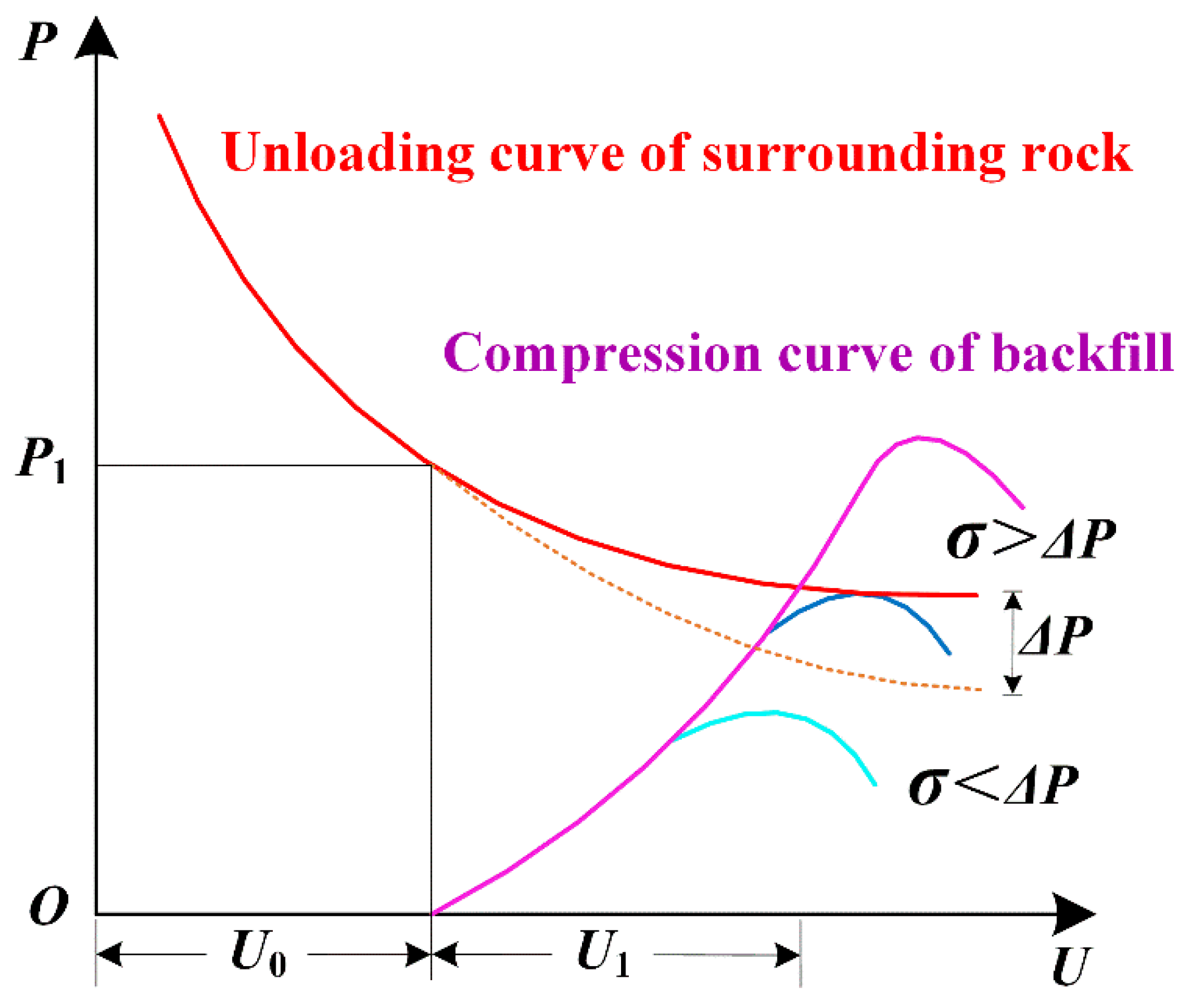
4.3. Damage and Failure Characteristics and Bearing Mechanism of Backfill Body

After entering the goaf, the filling slurry interacts with surrounding rock through flow settlement, osmotic dehydration, and consolidation hardening, including providing lateral pressure to the sliding trend of unloading rock block, supporting broken rock mass and primary cataclastic rock mass, and resisting the closure of surrounding rock in the stope. As a kind of multiphase composite medium, backfill will have different damage modes and failure modes under different confining pressure environments and loading conditions, and show obvious randomness and timeliness, especially under the action of complex stress state and multidirection strong disturbance.
As shown in Figure 8, after the ore body is excavated and unloaded, the surrounding rock begins to show pressure relief deformation, resulting in elastic deformation, plastic deformation, or rheology, which is manifested by the gradual reduction of stress, gradual increase of strain, and eventually stability. After entering the goaf, the filling slurry interacts with the surrounding rock through osmotic dehydration and consolidation hardening, including providing lateral pressure for the sliding trend of unloading rock block, supporting the broken rock mass and the original cataclasted rock mass, and resisting the closure of the surrounding rock of the stope. Considering the lag of filling operation and the consolidation and hardening process of the filling body, the deformation of the surrounding rock has begun and displacement U0 has been generated before the filling body plays a supporting role. After consolidation and hardening, the filling body begins to contact the surrounding rock and produces interaction force. Although it cannot prevent further deformation and pressure relief of the surrounding rock, it can slow down the pressure relief deformation curve of the original surrounding rock, reduce the amount of deformation, and reduce the pressure relief value ΔP. However, because the uniaxial compressive strength of backfill is generally less than 3–5 MPa (i.e., σ < ΔP), the backfill cannot provide rigid support for surrounding rock pressure relief deformation. Creep damage and plastic failure occur successively in the backfill, and even large-scale instability collapse [29,30] occurs.
Although low compressive strength of the filling body under the condition of stress concentration easily generates creep damage and plastic damage, the structure damage after the filling body can still occur under high ground pressure load. In the process of long-term bearing, it can also show that the creep strength is greater than the strain hardening characteristics of uniaxial compressive strength, which can effectively resist the deformation and failure of surrounding rock, maintain long-term stability. Therefore, different from the traditional rigid support with “small deformation” to absorb and store energy, the backfill absorbs the elastic deformation potential energy accumulated in rock mass through “large deformation”, delays its release rate, controls its action intensity and destruction effect, and achieves the support effect of “softness to overcome stiffness” [31].

4.4. Evaluation of Stope Backfill Effect

After filling the backfill slurry into the goaf, it is in a relatively closed state, so it is impossible to accurately evaluate the filling effect of the filling body. Therefore, it is often necessary to evaluate the filling effect of the stope by means of indoor proportioning test, numerical simulation, and field industrial test, as shown in Figure 9 [32].
(1)
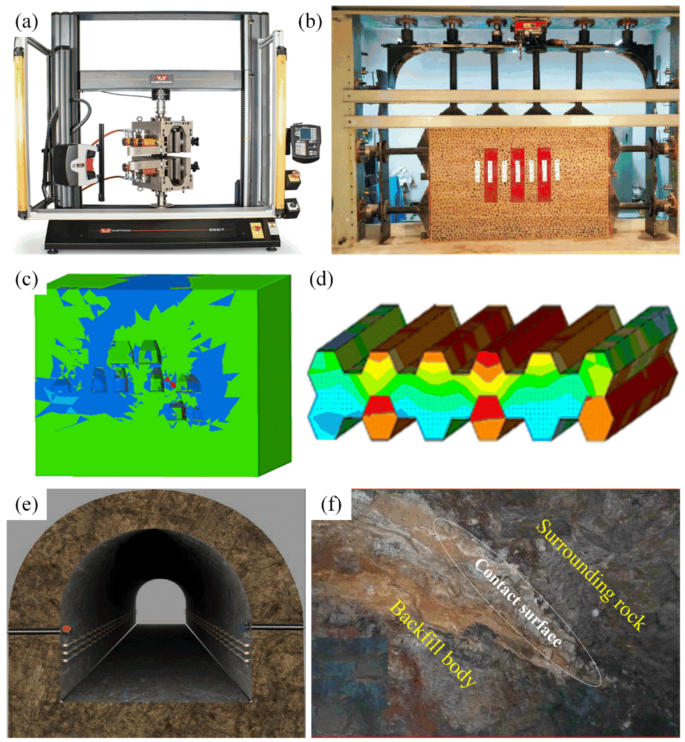
The indoor filling ratio test is one of the most effective means to objectively evaluate the stope filling effect. Uniaxial/triaxial compression tests were carried out to analyze the damage modes and failure modes of backfill under different confining pressures and loading conditions by focusing on the particle size composition, particle size grading, chemical composition, mass concentration, cement–sand ratio, internal friction angle, cohesion, etc., which affect the damage and failure characteristics of backfill. Impact load test was carried out to analyze the energy consumption threshold of filling under different loading rates and to construct the corresponding damage evolution equation. Acoustic emission tests were carried out to analyze the proportional relationship of strain energy released during crack propagation in the backfill. Transient information capture tools such as high-speed camera, ultra-dynamic strain gauge, and infrared imaging were used to analyze and analyze the microstructure changes and mesoscopic damage evolution of backfill.
(2)
Numerical simulation. Under the dynamic response of stope excavation and unloading, the rigid surrounding rock deforms and compresses the filling body to release elastic potential energy, while the soft plastic filling body absorbs and accumulates deformation energy continuously, forming a complex system involving stress field, displacement field, and energy field. Combined with the random damage model of cemented backfill and the compression deformation equation of uncemented backfill, numerical simulation software was used to conduct multiphysical field numerical simulation under the coupling action of surrounding rock and backfill, in order to reveal the release, absorption, and dissipation law of strain energy under the coupling action of rigid and flexible media.
(3)
Field industrial test. By selecting the typical standard of ore block and stope, according to the specification of two-step mining stope mining process, excavation unloading stope ground pressure monitoring network and real-time monitoring of stope roof and two displacement is established. Through field observation and contrast filling stope stability, real-time deformation monitoring and analysis is carried out, and soft surrounding rock-filling body medium interaction, bearing, and the coupling effect of regional support together are determined.

5. Discussion and Conclusions

With the development of science and technology, many research experts in China have begun to engage in the research of intelligent mine construction, but it is undeniable that the research and solution of practical engineering problems also greatly affects the development of China’s mining industry. Due to the different progress of mine development and different engineering and geological conditions, there are many potential engineering problems in China’s mines. Therefore, Chinese researchers have made great progress in practical engineering problems in the last 20 years, especially in the field of backfill mining method. In the next 10 years, and even 20 years, solving practical engineering problems is still the main keynote of the development of China’s mining industry and backfill mining method.
For example, Zhang et al. [33] proposed that safety should be considered in mining production, and numerical modeling methods such as Flac3D should be used for practical engineering and mining method optimization; again, for example, Zhang et al. [34] proposed that environmental concerns be incorporated into the evaluation and consideration of practical mining production and backfill processes, as China has introduced the concept of green mining since 2015.
Overall, as the last part of our series, Part III, also serving as a medium to lead readers to China’s mining industry, especially the practical engineering problems, can be roughly divided into three sections:
(1)
Calculation problems of backfill slurry transportation.
(2)
Reliability analysis of backfill pipeline system.
(3)
Stope backfill process and technology.
As a medium to guide readers to understand the development of China’s mining industry, this paper systematically reviews the research progress of the practical engineering problems in the stope (and goaf) backfill, which plays a role in the future development of backfill mining. At the same time, we also call on relevant researchers to actively invest in the research of backfill mining and promote the rapid development of the backfill mining method, which will undoubtedly bring good news to people all over the world.
Finally, we claim that the case report serves merely as a guide to starting a conversation, and we hope many more experts and scholars will be interested and engage in the research of this field.

Author Contributions

Conceptualization, S.L.; validation, H.Y.; investigation, H.Y.; resources, S.L.; writing—original draft preparation, S.L.; writing—review and editing, H.Y. and S.L.; visualization, H.Y.; supervision, H.Y.; project administration, X.W.; funding acquisition, S.L. All authors have read and agreed to the published version of the manuscript.

Funding

This research was funded by the National Natural Science Foundation of China (Grant No. 51804337) and the Natural Science Foundation of Hunan Province (Grant No. 2021JJ40745).

Acknowledgments

First of all, authors thank the financial support from the Natural Science Foundation of China (Grant No. 51804337) and the Natural Science Foundation of Hunan Province (Grant No. 2021JJ40745); Secondly, authors express the gratitude to the Chinese experts in the research field of backfill mining method for their effort in the development of China’s mining industry; Finally, authors express sincere thanks to Central South University.

Conflicts of Interest

The authors declare no conflict of interest.

References

  1. Yu, H.; Li, S. The Function Design for the Communication-Based Train Control (CBTC) System: How to Solve the Problems in the Underground Mine Rail Transportation? Appl. Syst. Innov. 2021, 4, 31. [Google Scholar] [CrossRef]
  2. Nardo, M.D.; Yu, H. Intelligent Ventilation Systems in Mining Engineering: Is ZigBee WSN Technology the Best Choice? Appl. Syst. Innov. 2021, 4, 42. [Google Scholar] [CrossRef]
  3. Yu, H. Application of traffic signal control and Internet of things technology in Urban Rail Transit. In Proceedings of the 2021 IEEE 2nd International Conference on Big Data, Artificial Intelligence and Internet of Things Engineering (ICBAIE), New York, NY, USA, 26–28 March 2021; pp. 974–977. [Google Scholar]
  4. Li, S.; Wang, G.; Yu, H.; Wang, X. Engineering Project: The Method to Solve Practical Problems for the Monitoring and Control of Driver-Less Electric Transport Vehicles in the Underground Mines. World Electr. Veh. J. 2021, 12, 64. [Google Scholar] [CrossRef]
  5. Yu, H.; Li, S.; Yu, J. Intelligent Monitoring and Control System for underground mine rail transportation based on communication-based train control (CBTC) system and AI computing. In Proceedings of the 2021 IEEE 2nd International Conference on Big Data, Artificial Intelligence and Internet of Things Engineering (ICBAIE), New York, NY, USA, 26–28 March 2021; pp. 704–707. [Google Scholar]
  6. Yu, H.; Zhao, C.; Li, S.; Wang, Z.; Zhang, Y. Pre-Work for the Birth of Driver-Less Scraper (LHD) in the Underground Mine: The Path Tracking Control Based on an LQR Controller and Algorithms Comparison. Sensors 2021, 21, 7839. [Google Scholar] [CrossRef] [PubMed]
  7. Qi, C.; Ly, H.B.; Le, L.M.; Yang, X.; Guo, L.; Pham, B.T. Improved strength prediction of cemented paste backfill using a novel model based on adaptive neuro fuzzy inference system and artificial bee colony. Constr. Build. Mater. 2021, 284, 122857. [Google Scholar] [CrossRef]
  8. Qi, C.; Guo, L.; Ly, H.B.; Van Le, H.; Pham, B.T. Improving pressure drops estimation of fresh cemented paste backfill slurry using a hybrid machine learning method. Miner. Eng. 2021, 163, 106790. [Google Scholar] [CrossRef]
  9. Zhao, X.; Liu, C.; Zuo, L.; Wang, L.; Zhu, Q.; Liu, Y.; Zhou, B. Synthesis and characterization of fly ash geopolymer paste for goaf backfill: Reuse of soda residue. J. Clean. Prod. 2020, 260, 121045. [Google Scholar] [CrossRef]
  10. Li, M.; Li, A.; Zhang, J.; Huang, Y.; Li, J. Effects of particle sizes on compressive deformation and particle breakage of gangue used for coal mine goaf backfill. Powder Technol. 2020, 360, 493–502. [Google Scholar] [CrossRef]
  11. Feng, X.; Zhang, Q. The effect of backfilling materials on the deformation of coal and rock strata containing multiple goaf: A numerical study. Minerals 2018, 8, 224. [Google Scholar] [CrossRef] [Green Version]
  12. Wang, C.; Gan, D. Study and Analysis on the Influence Degree of Particle Settlement Factors in Pipe Transportation of Backfill Slurry. Metals 2021, 11, 1780. [Google Scholar] [CrossRef]
  13. Cao, S.; Xue, G.; Yilmaz, E.; Yin, Z. Assessment of rheological and sedimentation characteristics of fresh cemented tailings backfill slurry. Int. J. Min. Reclam. Environ. 2021, 35, 319–335. [Google Scholar] [CrossRef]
  14. Wu, J.; Feng, M.; Mao, X.; Xu, J.; Zhang, W.; Ni, X.; Han, G. Particle size distribution of aggregate effects on mechanical and structural properties of cemented rockfill: Experiments and modeling. Constr. Build. Mater. 2018, 193, 295–311. [Google Scholar]
  15. Yang, L.; Qiu, J.; Jiang, H.; Hu, S.; Li, H.; Li, S. Use of cemented super-fine unclassified tailings backfill for control of subsidence. Minerals 2017, 7, 216. [Google Scholar] [CrossRef] [Green Version]
  16. Liu, L.; Fang, Z.; Qi, C.; Zhang, B.; Guo, L.; Song, K.I. Numerical study on the pipe flow characteristics of the cemented paste backfill slurry considering hydration effects. Powder Technol. 2019, 343, 454–464. [Google Scholar] [CrossRef]
  17. Chen, Q.; Zhang, Q.; Wang, X.; Xiao, C.; Hu, Q. A hydraulic gradient model of paste-like crude tailings backfill slurry transported by a pipeline system. Environ. Earth Sci. 2016, 75, 1–9. [Google Scholar] [CrossRef]
  18. Yu, H.; Li, S.; Wang, X. The Recent Progress China Has Made in the Backfill Mining Method, Part I: The Theory and Equipment of Backfill Pipeline Transportation. Minerals 2021, 11, 1274. [Google Scholar] [CrossRef]
  19. Shu, C.; Zhang, J.; Liu, C.; Ma, Q.; Han, Y.; Jiang, J. Paste-like pumping backfilling technique with high stowing gradient and long distance. DEStech Trans. Eng. Technol. Res. 2017. [Google Scholar] [CrossRef]
  20. Li, S.; Zhao, Z.; Yu, H.; Wang, X. The Recent Progress China Has Made in the Backfill Mining Method, Part II: The Composition and Typical Examples of Backfill Systems. Minerals 2021, 11, 1362. [Google Scholar] [CrossRef]
  21. Luan, H.; Jiang, Y.; Lin, H.; Wang, Y. A new thin seam backfill mining technology and its application. Energies 2017, 10, 2023. [Google Scholar] [CrossRef] [Green Version]
  22. Wu, D. Case Study of Cemented Coal Gangue-Fly Ash Backfill. In Mine Waste Management in China: Recent Development; Springer: Singapore, 2020; pp. 195–204. [Google Scholar]
  23. He, R.; Jin, H. Permafrost and cold-region environmental problems of the oil product pipeline from Golmud to Lhasa on the Qinghai–Tibet Plateau and their mitigation. Cold Reg. Sci. Technol. 2010, 64, 279–288. [Google Scholar] [CrossRef]
  24. Chang, Q.; Chen, J.; Zhou, H.; Bai, J. Implementation of paste backfill mining technology in Chinese coal mines. Sci. World J. 2014, 2014, 821025. [Google Scholar] [CrossRef]
  25. Cheng, W.C.; Li, G.; Liu, N.; Xu, J.; Horpibulsuk, S. Recent massive incidents for subway construction in soft alluvial deposits of Taiwan: A review. Tunn. Undergr. Space Technol. 2020, 96, 103178. [Google Scholar] [CrossRef]
  26. Yu, H. Special mechanical component applied to erection of horizontal filling pipe in collapse roadway of the underground mine. Mining 2021. [Google Scholar] [CrossRef]
  27. Wang, L.; Chen, G.; Chen, S. Experimental study on seismic response of geogrid reinforced rigid retaining walls with saturated backfill sand. Geotext. Geomembr. 2015, 43, 35–45. [Google Scholar] [CrossRef]
  28. Lu, H.; Qi, C.; Chen, Q.; Gan, D.; Xue, Z.; Hu, Y. A new procedure for recycling waste tailings as cemented paste backfill to underground stopes and open pits. J. Clean. Prod. 2018, 188, 601–612. [Google Scholar] [CrossRef]
  29. Zhao, Y.; Taheri, A.; Karakus, M.; Chen, Z.; Deng, A. Effects of water content, water type and temperature on the rheological behaviour of slag-cement and fly ash-cement paste backfill. Int. J. Min. Sci. Technol. 2020, 30, 271–278. [Google Scholar] [CrossRef]
  30. Zhang, J.; Li, M.; Taheri, A.; Zhang, W.; Wu, Z.; Song, W. Properties and application of backfill materials in coal mines in China. Minerals 2019, 9, 53. [Google Scholar] [CrossRef] [Green Version]
  31. Zhang, J.; Deng, H.; Taheri, A.; Deng, J.; Ke, B. Effects of superplasticizer on the hydration, consistency, and strength development of cemented paste backfill. Minerals 2018, 8, 381. [Google Scholar] [CrossRef] [Green Version]
  32. Zhao, X.; Fourie, A.; Qi, C.C. An analytical solution for evaluating the safety of an exposed face in a paste backfill stope incorporating the arching phenomenon. Int. J. Miner. Metall. Mater. 2019, 26, 1206–1216. [Google Scholar] [CrossRef]
  33. Li, S.; Zhang, R.; Feng, R.; Hu, B.; Wang, G.; Yu, H. Feasibility of Recycling Bayer Process Red Mud for the Safety Backfill Mining of Layered Soft Bauxite under Coal Seams. Minerals 2021, 11, 722. [Google Scholar] [CrossRef]
  34. Li, S.; Zhang, Y.; Feng, R.; Yu, H.; Pan, J.; Bian, J. Environmental Safety Analysis of Red Mud-Based Cemented Backfill on Groundwater. Int. J. Environ. Res. Public Health 2021, 18, 8094. [Google Scholar] [CrossRef]
Figure 1. The relationship between velocity distribution of two-phase flow and structural flow and hydraulic slope: (a) the motion state and structure of two-phase flow; (b) the motion state and structure of the structural flow; (c) two-phase flow slope law; (d) slope law of structural flow.
Minerals 12 00088 g001
Figure 2. Common layout scheme of filling pipeline.
Minerals 12 00088 g002
Figure 3. Analysis of self-flow transportation mode and wear of backfill slurry pipeline.
Minerals 12 00088 g003
Figure 4. Pumping system: (a) cavitation and erosion; (b) pressure relief device configuration drawing.
Minerals 12 00088 g004
Figure 5. Layout of filling borehole and horizontal pipeline connecting accident treatment valve and accident pool: (a) Main view; (b) Top view.
Minerals 12 00088 g005
Figure 6. Schematic diagram of common filling retaining wall: (a) Wooden filling retaining wall; (b) Brick retaining walls; (c) Steel mesh flexible filling retaining wall; (d) Concrete retaining walls; (e) Hydraulic filling retaining wall trolley; (f) Hydraulic filling retaining wall.
Minerals 12 00088 g006
Figure 7. Commonly used filling slurry filtration device: (a) Geotextile drainage; (b) Drainage hole drainage; (c) Drainage of drainage wells; (d) New pumping, drainage, and filtration units.
Minerals 12 00088 g007
Figure 8. Compressive deformation curves of surrounding rock and filling body.
Minerals 12 00088 g008
Figure 9. Backfill effect evaluation: (a) Filling body compression test; (b) Similarity model test; (c) Numerical simulation analysis of goaf; (d) Stope stability analysis; (e) Ground pressure detection; (f) Field industrial tests.
Minerals 12 00088 g009
Publisher’s Note: MDPI stays neutral with regard to jurisdictional claims in published maps and institutional affiliations.

