Article

Interpreting the Chemical Variability of Iron Smelting Slag: A Case Study from Northeastern Madagascar

Department of Geoscience, University of Fribourg, 1700 Fribourg, Switzerland
*
Author to whom correspondence should be addressed.
Minerals 2021, 11(8), 900; https://doi.org/10.3390/min11080900
Submission received: 13 July 2021 / Revised: 7 August 2021 / Accepted: 16 August 2021 / Published: 19 August 2021
(This article belongs to the Special Issue Mineralogy, Trace Elements and Isotopic Tracers in Archaeometallurgy)

Abstract

:
The archaeological remains of a metallurgical workshop were excavated at Amboronala (northeast of Madagascar/1000–1200 CE). The bulk mineralogical (X-ray Diffraction) and chemical (X-ray Fluorescence) data on ores, building materials, and slag are used to carry out a mass balance calculation. The results show an important variability from one smelt to the other, reflecting a poorly controlled process. During each smelt, a given amount of building material contributes to the formation of the slag, and the conditions of reduction allow the extraction of a given amount of metal. These two main factors influence the composition of the slag independently and variably. This finding allows to make some inference on the origin of the technique and the organization of the production can be made.

1. Introduction

The northeastern coast of Madagascar was settled around the 9th century CE by seafaring people, the so-called Rasikajy [1,2]. More than 600 graves were excavated at Vohémar, revealing a funeral tradition of Muslim origin and a spectacular range of imported goods from the Persian Gulf, India and China [3,4,5]. Since 2017, the project “Pots, Stones and Iron by the Rasikajy” aims to investigate the ancient exploitation of mineral resources through field and laboratory work [6]. In this paper, we will present the bulk chemical analyses of materials from a single slag heap. The recipe used is always the same, processing the same raw materials and using the same furnace. Unexpectedly, the composition of the slag is highly variable. This leads us to discuss hypotheses about the social organization of the production.
The presence of iron smelting slag in northeastern Madagascar was formerly reported by several authors [1,7,8]. During our recent surveys, around 150 small slag heaps were identified [9]. The total amount of slag can be estimated in the range of 500 to 1000 tons. They occur along the coast, mainly between Vohémar in the north and Antalaha in the south (Figure 1). At Benavony, Matavy and Amboronala, smelting workshops were excavated and test pits were made at two other sites. The remains are typical for a kind of bloomery process [10,11,12,13].
The excavations revealed vanishing remains of simple bowls dug at a depth of 10 to 20 cm into the sandy substratum (Figure 2). The internal diameter of the structures ranges from 50 to 70 cm. There is a reddish halo resulting from the heat impact and a dark filling sediment rich in charcoal. No clay lining is used. The few and very fragile wall fragments are made of poorly sintered sand. The presence of a surrounding wall, probably no more than 30 cm high, can be assumed. A single short cylindrical tuyere, made of bored stone or ceramic, went through the wall at the ground level. The small diameter of the single, funnel-shaped duct indicates the use of bellows. Slag accumulates at the bottom of the bowl but, if needed, it could flow outside through an opening made in the sand wall. The smelting technique based on this very simple bowl furnace was in use throughout the entire district. This metallurgical production was dated between 1000 and 1400 CE from 26 radiocarbon dates sampled from 16 different slag heaps [14].

2. Materials and Methods

At Amboronala, we extensively excavated the small workshop MBR140 [14]. Representative samples of the various materials involved in the process of iron smelting were collected and registered. At the Department of Geosciences of the University of Fribourg, the samples were processed for geochemical, mineralogical and petrographic investigations. In this paper, we present the results of the bulk chemical analyses by X-ray fluorescence spectrometry (XRF) and bulk mineralogical identification by X-ray diffraction (XRD).
After cutting and cleaning, an amount of 50 to 100 g of material was powdered with oscillating grinder in a tungsten carbide vessel to obtain a homogeneous powder with a grain size of 75 μm.
XRF measurements were performed with a Zetium X-ray wavelength dispersive spectrometer (Malvern-PANalytical, Malvern, UK). Major components (Si, Ti, Al, Fe, Mg, Ca, Na, K and P) are measured using the routine program on fused glass beads made of 0.7 g of calcinated powder, 0.35 g of lithium fluoride (LiF) and 6.65 g of lithium tetraborate (Li2B4O7). The analytical error is below 1% relative. The program is calibrated using 40 international reference materials [17]. Trace elements are measured on pressed powder pellets (12 g) using the Pro-Trace analytical software of Malvern-PANalytical (version 6.1., Malvern-PANalytical, Malvern, UK). Out of 40 trace elements measured, we present only the 13 ones with significant results (Ba, Ce, Co, Cr, Cu, La, Mn, Ni, Rb, Sr, V, Y, Zr). The analytical error is below 10% relative. Measurements below 2 ppm are not considered.
XRD measurements were made using an Ultima IV diffractometer (Rigaku, Tokyo, Japan) and the identification software X’Pert Highscore Plus (Malvern-PANalytical, Malvern, UK). Components below 5% are difficult to detect especially since the presence of a glassy phase increase the background effect.

3. Mineralogy and Chemical Composition of the Metallurgical Waste of the Iron Smelting Workshop MBR140

Amboronala is a small village located to the south of the Lokoho River estuary. Nearby, smelting remains are scattered along large dunes made up of Quaternary sandy sediments. Ten slag heaps arranged in three clusters spread over two kilometers. The workshop MBR140 was thoroughly excavated, and test pits were dug on other heaps (Figure 3 and Figure 4).

3.1. The Sandy Substratum and the Building Materials of the Furnace

Along the northeastern coast, between the seashore and the hills of the hinterland, a continuous strip of land, 1 to 5 km wide, is made up of Quaternary loose sands. The topography is quite flat with longitudinal dunes and many shallow marshy depressions. These deposits are the result of the sea and the wind reworking the detrital sediments transported by the numerous rivers draining the mountainous hinterland. The sea level fluctuations caused by successive glaciations during the Quaternary are responsible for the reworking and deposition of the sand and the topographic features. The old Proterozoic crystalline basement is the main source of the sand grains [18,19].
At MBR140, the substratum is made of loose whitish sand. In the test pit, sinked one meter below the archaeological level, no variation was observed. One sample of the substratum has been collected during the excavation (MBR14901, Table 1). The X-ray diffraction spectrum shows dominant quartz alongside significant plagioclase and alkali feldspar. The peaks of the muscovite-illite are visible, probably formed as alteration products on the feldspars. The bulk chemical composition shows a high silica content: 78 wt.% SiO2 (Table 1). Alumina and potassium, sodium and calcium oxides are the other important contributors and reflect the presence of the feldspars. The trace element concentrations are quite low. The most abundant are barium (Ba), rubidium (Rb) and strontium (Sr), typical for feldspars. Titanium (Ti), manganese (Mn), chromium (Cr), vanadium (V) and zirconium (Zr) are low, attesting the absence of heavy minerals in the sand.

3.2. The Iron Ores

At MBR140, several concentrations of small ferruginous pisolitic concretions were located close to the slag heaps (Figure 3). These concretions cannot be formed naturally in the Quaternary sand dunes and must have been brought by the metallurgists to be smelted. Similar pisolites were observed, partially melted, inside bottom furnace slag. Additionally, a big flat stone was also brought to the workshop and used as an anvil to crush the ore [14].
Cretaceous basaltic lava flows, related to the separation between Madagascar and the Indian Plate, are cropping out at the eastern fringe of the Proterozoic basement, forming the first range of hills inland from Amboronala (Figure 1) [20]. These are ideal source rocks for the formation of an iron-rich lateritic cover containing pisolitic concretions. When walking into the hills, we could indeed collect similar concretions on the surface of the red soil.
The ore samples presented in this paper were collected nearby the slag heaps at MBR140. Each sample consists of a batch of 50 g of pisolites. Samples a and b are from the same large batch separated randomly using a splitter. In this case, the aim of the analysis is to produce a representative mean composition.
The concretions show red to brown shiny surfaces. XRD spectra show peaks of iron oxides, hematite and goethite, as the main components, together with small amounts of kaolinite and quartz. The samples have a particularly high iron oxides grade, with an average of 81.3 wt.% Fe2O3tot (Table 1). The ratio of SiO2:Al2O3 is close to 1:1, which is consistent with the presence of kaolinite. There is a significant amount of titanium oxide, averaging at 1.2 wt.% TiO2. Magnesium, calcium, potassium and sodium oxides are almost absent, as expected in a laterite. Chromium (Cr) and vanadium (V) are the most abundant trace elements, probably replacing iron in the lattice of the iron-rich minerals. Their concentrations are in the range of 1000 ppm and the ratio Cr:V is close to 1:1. Manganese (Mn: 250 ppm), copper (Cu: 100 ppm) and zirconium (Zr: 100 ppm) are noticeable. In contrast to the sand, barium (Ba), rubidium (Rb) and strontium (Sr) concentrations are very low.

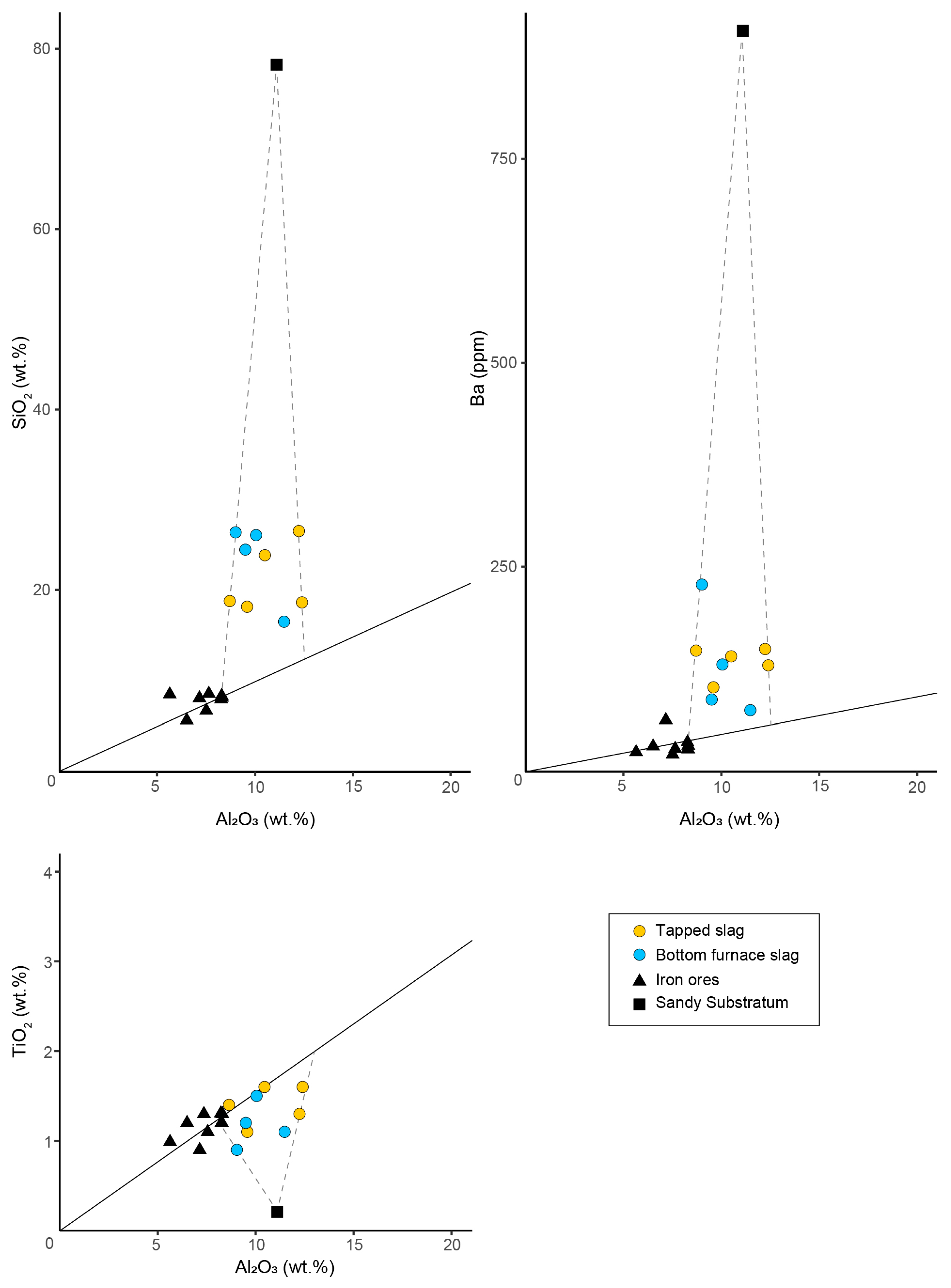
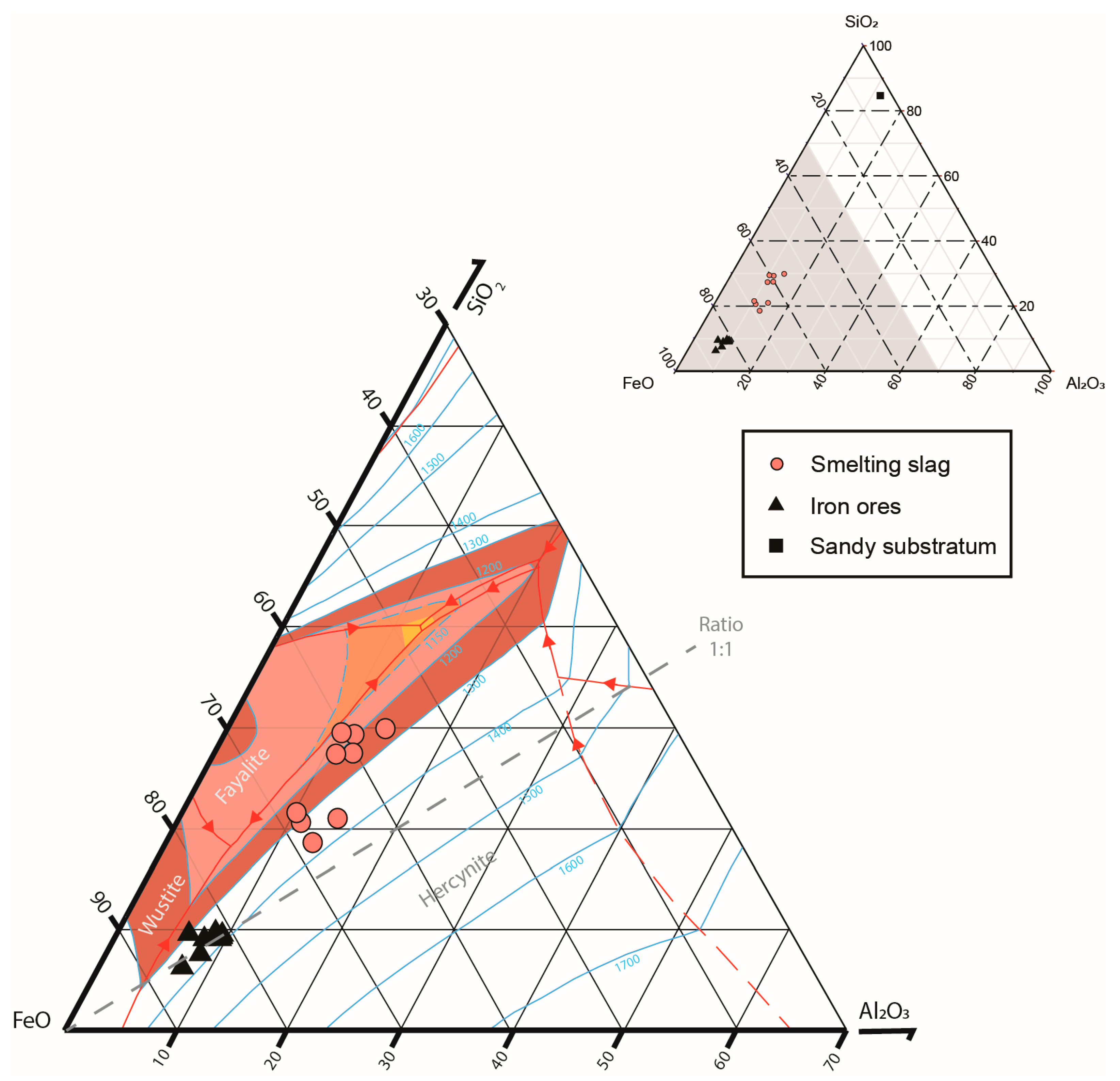
3.3. The Smelting Slag

The slag formed during smelting is either accumulated at the bottom of the internal pit or tapped outside of the furnace. At MBR140, the two small heaps consist almost entirely of small fragments of cord-like tapped slag. The bottom slag blocks were found inside the working pit excavated in the sandy substratum (Figure 3, feature 143). They were used to stabilize the floor and the walls of the pit.
Bottom furnace slag blocks are roughly hemispherical with a slight depression on the upper surface which reflects the position of the air flow of the tuyere (Figure 2). The lower surface often consists of a sandy crust, 1 to 3 mm thick. In addition, unmelted sand grains are frequently bonded to the upper surface. Cross-sections also show very siliceous zones in the upper part of the blocks. During the process, the smelters dug a channel directly into the sand to evacuate the excess of slag. Elongated tapped slag fragments frequently present a characteristic V-section indicating the shape of the small draining channel. Sand grains are also frequently observed on the lower surface of the tapped slag pieces. In a few cases, we observed the last flow of tapped slag still attached to the hemispherical internal block.
A representative selection of slags was collected according to morphology. They were sawed to remove all sand rich external surfaces, and internal cavities were cleaned. On the X-ray spectra, fayalite and a titanium rich spinel are always present. Wuestite is occasionally detected. The slag is always rich in iron oxide, but the amount is quite variable, ranging from 55 to 67 wt.% Fe2O3tot (Table 2). The ratio between Alumina (8.7–12.4 wt.% Al2O3) and silica (16.5–26.5 wt.% SiO2) is highly variable from one sample to another (Figure 5). Titanium oxide contents are remarkably high, around 1.3% in average. Oxides of calcium (0.4–2.1 wt.% CaO) and potassium (0.2–1.1 wt.% K2O) are also important components. No correlation can be seen between these two elements. The most abundant trace elements are vanadium (V: 750–1500 ppm) and chromium (Cr: 400–1000 ppm). The grades are variable, but the ratios are similar. Manganese shows a strong variability (Mn: 120–1200 ppm). There are small quantities of barium, rubidium and strontium.
The slag of MBR140 present a strong variability, but there is no systematic chemical difference between the two morphological groups. Both the five tapped and the four bottom furnace slags show a similar range of compositions.

4. Mass Balance and Study of the Variability of the Smelting Process

The archaeological and compositional data available from the MBR140 smelting workshop allow to perform a mass balance calculation [21,22,23,24,25].

4.1. Principle of the Mass Balance Calculation

The mass balance approach is based on the principle of the conservation of mass. The mass of the materials introduced into the furnace must be equal to the mass of the materials coming out of it. In a simplified approach, only four components will be considered to make the calculation:
Principle            Ore + Contamination = Slag + Iron,
Air and fuel are also introduced in the furnace and participate in the reaction to produce the combustion gases. The combustion gases will evacuate the volatile substances liberated by the different materials at high temperature. Water from hydrated minerals like clays is lost. There is also always a significant quantity of oxygen lost from the reduction of the iron oxides of the ore. For this reason, if the calculation is made including oxygen, then the two sides of the equation will not be of equal mass. To avoid this bias, it is recommended to recalculate the compositions as elements, without oxygen.
The aim of the calculation is to estimate the quantities of the different components in the system, relatively to one of them.
System   (M × Ore) + (W × Contamination) = (S × Slag) + (F × Iron),
The factors M, W, S and F are the relative quantities of the respective components. As the fieldwork data often allow to estimate the total mass of slag found at a workshop, it makes sense to calculate the factor M, W and F relatively to one unit of slag (S = 1) to evaluate the global production of iron. The same calculation could be made for M, W or F equal to 1. When M is equal to 1, the factor F reflects the yield directly.
Theoretically, for one given system, the 4 factors should be fixed for the system as a whole and for each element separately. Using 3 equations, for 3 different elements including iron, it is possible to find a unique solution for the 3 unknown factors. It is recommended to use the chemical composition data obtained for the more abundant elements, because they will show less relative variability than minor components. In most cases, the calculations must be based on Fe, Si and Al. The measured or averaged grade in wt.% of a material can be presented as g per 100 g of this material.
Si    (M × g of Si in 100 g of Ore) + (W × g of Si in 100 g of Contamination) = (1 × g of Si in 100 g of Slag)                
Al   (M × g of Al in 100 g of Ore) + (W × g of Al in 100 g of Contamination) = (1 × g of Al in 100 g of Slag)              
Fe   (M × g of Fe in 100 g of Ore) + (W × g of Fe in 100 g of Contamination) = (1 × g of Fe in 100 g of Slag) + (F × g of Fe in 100 g of Iron)
Silicon and aluminum are assumed to be absent from the metallic phase of the bloom, because they are not reduced in the conditions reached during the bloomery process, and their oxides cannot be dissolved in the solid metallic phase. For this reason, the iron component is omitted in Equations (3) and (4), and the F factor is calculated following Equation (5).
The potential contamination must be investigated as it can be a complex parameter. There is always a contamination from the ashes of the fuel [26,27,28,29]. The most common fuel is charcoal, and it contains about 5 wt.% of ashes, mainly calcium and potassium oxides (CaO, K2O). The contamination always affects Ca and K, even though Mg, Na and P can be impacted. In special cases, other elements can be affected, including trace elements. In general, not all the ashes are incorporated in the slag. The ore fed into the furnace is the result of a more or less complex process of beneficiation [12]. It is frequent that some materials from the gangue or from the host rock are still present in the final concentrate. The building materials of the furnace walls undergo partial melting during the process. Such partially melted building materials are found during excavation, and their composition can be measured experimentally [21,30]. Finally, the deliberate addition of another substance can be considered. It is expected that this addition aims to lower the melting point of the slag, and in this case, the substance can be termed a flux. In the archaeological record, there is only limited material evidence supporting the proper use of a flux for the production of iron by the bloomery process [12]. Instead, this practice is well documented for the production of cast iron in blast furnaces during the late Middle Ages in Europe.
Theoretically, the factors M, W and F calculated from 3 elemental equations should apply to all other elements. In practice, it is never the case, for several reasons.
First, during the smelting process at high temperature, several elements will fractionate between the combustion gas, the solid metallic product and the melted slag [22,31,32,33]. It is not possible to measure the composition of the gas and the composition of the metallic product can hardly be evaluated from archaeological remains. Hence, the measured values for the fractionating elements will not fit the calculated results. Several substances can be partially or totally volatilized, such as elemental sodium (Na), potassium (K) and zinc (Zn) or oxides of sulfur (SO3) and arsenic (As2O3) [34,35,36]. Several other elements can be reduced to the metallic state in the conditions of the bloomery process [37]. Copper (Cu), nickel (Ni) and cobalt (Co) will enter easily in the metallic phase. Other precious (Ag, Au, Pt, Os) and base metals (Pb, Sn) should behave similarly but are very rarely present at a significant level in iron ores [38]. Other elements can be partly affected because they are difficult to reduce in the conditions of the bloomery process. Phosphorus (P) is reduced under conditions very close to the ones of iron [39]. Chromium (Cr), manganese (Mn) and vanadium (V) demand stronger conditions, but these are not impossible to reach during the bloomery process [40,41]. At very high conditions, silica (SiO2) begins to react, and a few percent silicon (Si) are a common feature in cast irons.
On the other hand, the knowledge about the archaeological materials involved in the process is not always satisfactory. In general, the slag and the furnace building materials can be well studied, but the ore and the metallic product are more difficult to characterize. Finally, it is more or less impossible to chemically define the ashes.
In the end, only a small number of elements can eventually provide valuable information for the calculation of the mass balance. On the other hand, the behavior of the fractionating elements can provide useful evidence to understand the efficiency of the smelting process. The understanding of the contamination is also essential for the characterization of the smelting process.
The ideal components for the calculation would not be affected by any of the problems presented above, which are contamination and fractionating. In practice, no element is ideal, but many can be used to produce satisfactory calculations for a given system. The suitable elements will be the ones with a significant contrast in the ore and the other materials involved in the system.
For lateritic iron ores, the low Si:Al ratio allows to use aluminum. In marine oolithic ores, very high calcium is expected, sometimes with magnesium. Other elements are typical for specific types of iron ores and rare in most other natural materials, like manganese (Mn), chromium (Cr) and titanium (Ti).

4.2. Mass Balance Calculation for the Smelting Process at MBR140

At Amboronala MBR140, the contamination by the sand of the substrate is obvious through several lines of evidence. First, sand grains, partially or non-melted, can be observed directly on the surface and inside the slag. Moreover, the absence of solid wall fragments could indicate that the walls are weakly indurated by the firing process and the loose sand can mix easily with the slag. One sample of sand was taken and analyzed (Table 1, MBR14901). The compositions of the iron ore samples are very homogeneous. The mean values can be used in the calculation (Table 1, Average ore).
On the contrary, the analyses of the slag pieces show a very strong variability (Table 2). The number of samples (only 9) is much too small to statistically demonstrate the representativity of the mean values. In this case, a single calculation based on the mean values is not significant. In contrast, the calculation can be performed for each piece, and the results reflect the variability from one smelt to another, both in terms of the efficiency of the reduction reaction and of the proportion of contamination by the sand (Table 3). At Amboronala MBR140, the variability within a single operation cannot be investigated because it is impossible to identify the different fragments of a single smelting operation. In other case studies, this internal variability has been shown to be limited [21,26,42].
Silicon and aluminum are present both in the ore and in the sand, at measurable grades and with highly contrasted ratios (Figure 5). These allow the calculation of M, W and F using Si, Al and Fe equations (Table 3, lines 1.1, 1.2 and 1.4). One must keep in mind that in such a system of equations, with any defined ore, sand and slag, there is always one single mathematical solution, but the significance of the calculated numbers is given only if the materials are identified correctly. To demonstrate that the ore and the sand are really the ones involved in the formation of the slag, at least one other element should give results in agreement with the calculated M and W. At Amboronala, titanium can be used to confirm the correct identification of the materials (Figure 5). The grades of Ti are high enough in all materials, and the ratios Si:Ti and Al:Ti are different in the ores and the sand. For 8 pieces of slag out of 9, the measured and calculated grades for Ti are quite similar, within 10% relative uncertainty (Table 3, lines 1.5 and 1.6). Only for the sample MBR14010, there is no good agreement. This particular case can be explained by the use of raw materials with a small difference in composition, possibly pisolites collected in another area.

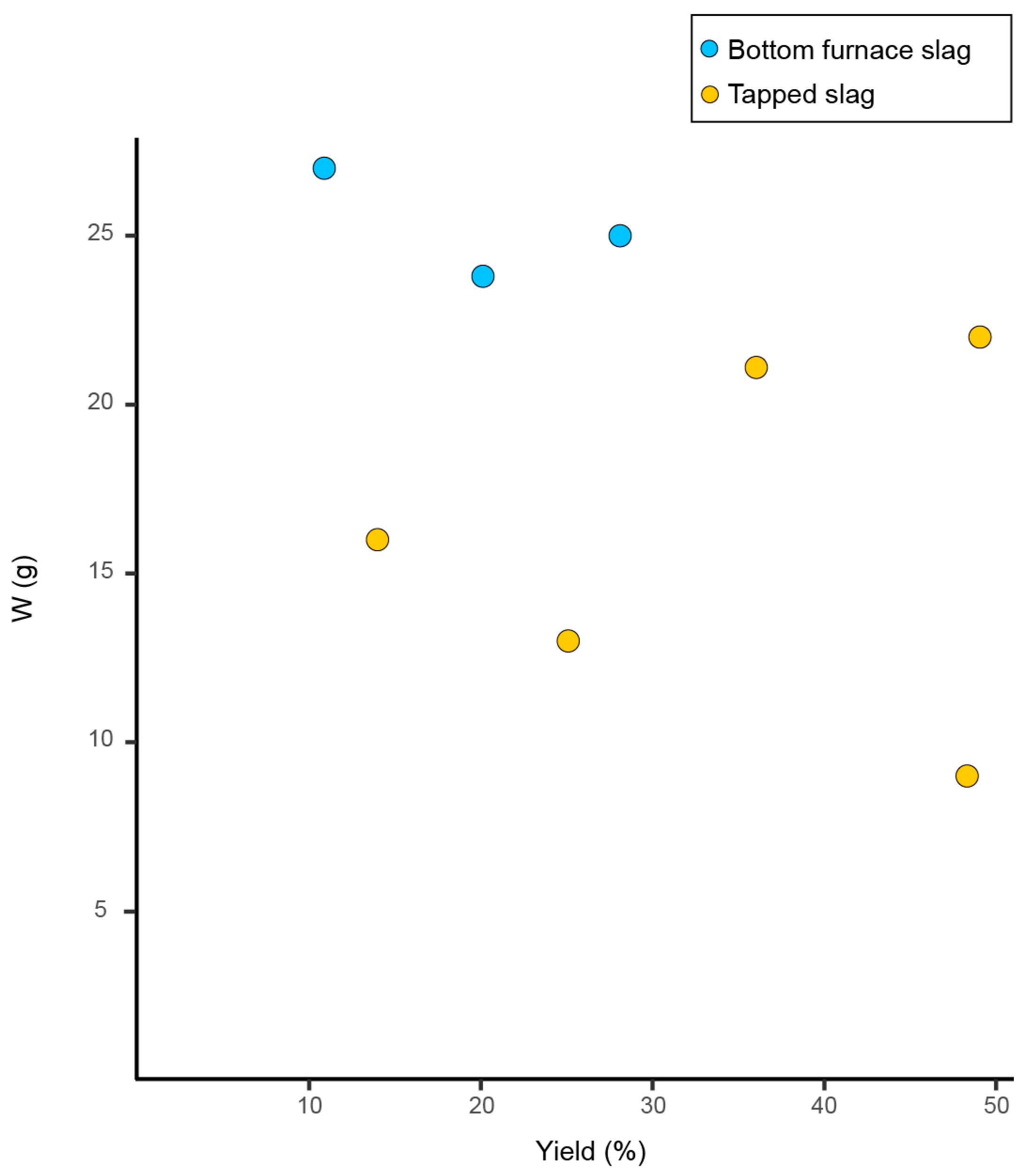
4.3. Variability of the Iron Production

The amount of iron produced per unit of ore varies significantly from one sample to the other: the calculated values range from 6 g to 28 g for 100 g of ore (Table 3, line 2.4). With the lower values, below 10 g, the product was really small. The smelters were close to failure, especially since the metal remained dispersed, and no bloom is produced. On the contrary, the highest values, near 30 g, were a nice success. This variation in the amount of iron produced reflects the variability of the efficiency of the reaction of reduction. Three main physico-chemical parameters, linked one to another, are responsible for the efficiency of the reaction: temperature, time and the partial pressure of carbon monoxide. These parameters are related to the technical gestures of the smelters and the way they drive their furnace. At Amboronala, the smelters used small and simple bowl furnaces. Compared to other bloomery furnaces of the same period, the architecture is not very efficient for saving heat and concentrating the reducing gases [43,44,45]. The use of bellows can be inferred from the shape and size of the tuyere (Figure 2). Apparently, the smelters were not able to control the reduction process systematically. Fortunately, because the ore is high grade, it is not too difficult to produce a minimum amount of iron under poor conditions.
There are not many arguments to estimate the quantity of ore processed during one single smelt. Considering the size of the furnace, maybe a batch of 10 L, about 20 kg, is a reasonable estimate. The worst smelt (MBR14009) would have given only 1.2 kg of metal, which would have been a porous block of the size of a small fist. The best bloom (MBR14003) reached more than 5 kg, an uncompacted block of about 1 L.

4.4. Variability of the Contamination

At Amborolana, the sand always contributes to the formation of the slag. The contamination is highly variable: between 6 g and 32 g per 100 g of ore (Table 3, line 2.2). The amount of slag always raises with increasing contamination (Table 3, line 2.3). The bottom furnace slags show a slightly more contamination than the tapped slag, which is consistent with the macroscopic observations.
As the pisolitic ore containing kaolinite is rich in aluminum with a low Si:Al ratio, the effect of the contamination with a silica-rich sand is a lower melting temperature of the slag. On the ternary phase diagram for the system FeOn-SiO2-Al2O3, it can be seen that a slag with a Si:Al ratio of 1:1 will melt above 1400 °C (Figure 6). This thermal range is rather high and difficult to reach in a small and open bowl furnace. In all cases, the addition of silica will decrease the melting point of the slag. At Amboronala, most of the slag compositions plot above the 1200 °C isotherm, and a few pieces are close to 1400 °C. Apparently, it has been difficult for the smelters to melt the slag, and this is reflected by the irregular shape of many of the fragments.
However, the contamination by the sand is not correlated to the yield (Figure 7). A similar yield is calculated for MBR14003 and MBR14004, but the amount of sand incorporated is about three times higher for MBR14003 than for MBR14004. On the other hand, the level of contamination is similar for MBR14003 and MBR14007, but the production of iron is 28 g and 8 g, respectively. The efficiency of the reduction reaction is not directly linked to the proportion of contamination.

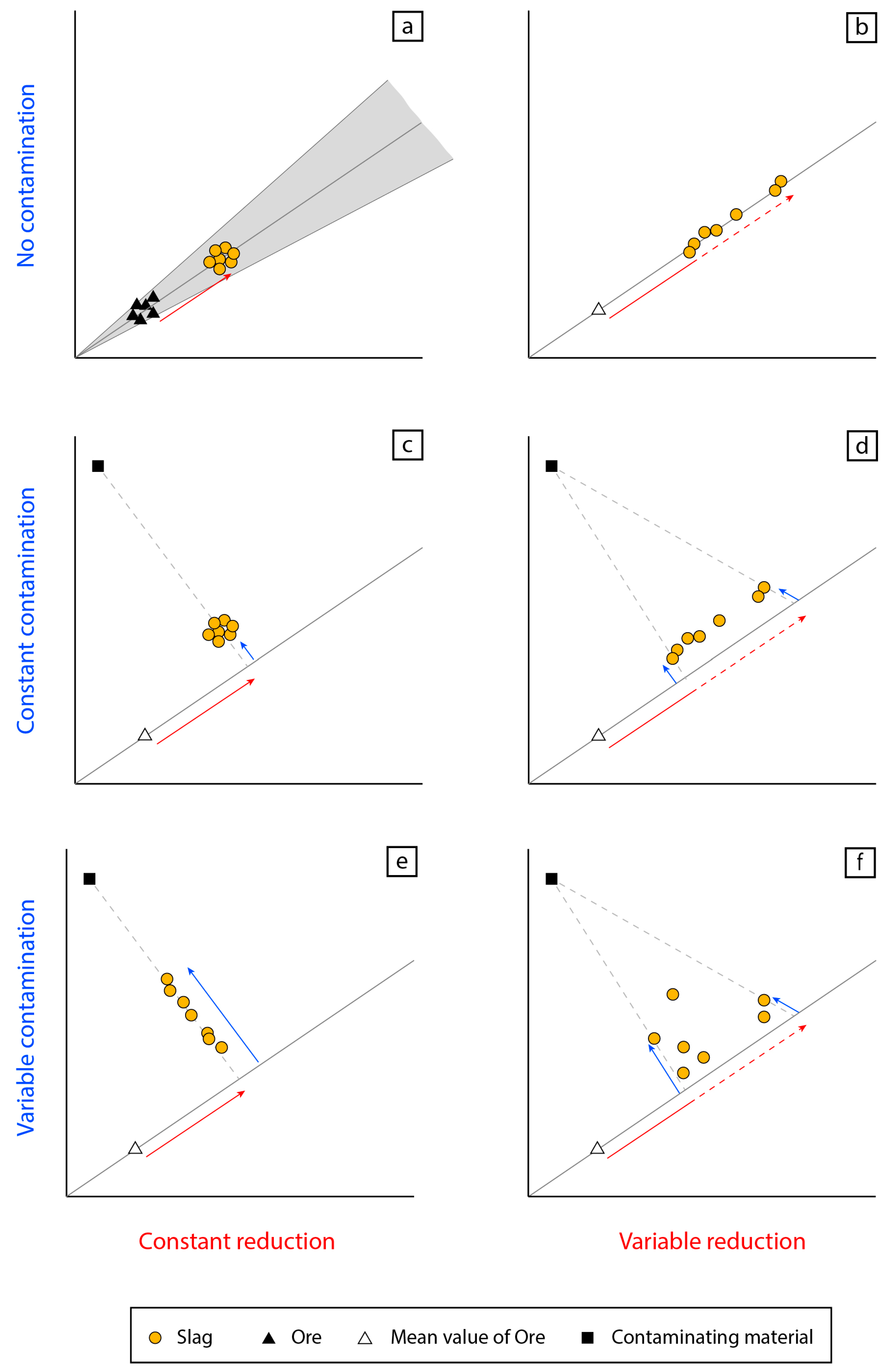
5. General Approach of the Variability Inside a Single Technology

The data from Amboronala led us to a more general approach of the variability in slag composition. Smelting slag is the result of repetitive smelting operations following a given technique. A technique is characterized by the raw materials used as well as the way the smelt is carried out [47]. The composition of the slag reflects both aspects. Both must be investigated at the level of a single sample but also within an assemblage. The ore is the first contributor to the slag. There is a huge range of natural ores. Some of them are homogeneous with a very constant composition; others are highly variable. The beneficiation process modifies the composition of the ore. The building materials of the furnace interact frequently during the process and provide a contribution to the formation of the slag. Other forms of contamination are possible, including the voluntary addition of a flux, for example. Together, the ore and the contaminating materials provide the chemical stock to the slag. If the two components present a chemical contrast, it is possible to identify their contribution and decipher the slag composition.
An important point related to the management of the furnace is the efficiency of the reaction of reduction. If the conditions are strong (high temperature, long duration, high availability of reducing agent), a greater proportion of the metallic oxide will be reduced to the metallic state. In the bloomery process, the conditions are not very strong, and a variable proportion of the iron oxide is not reduced and enters the slag.
When good archaeological and chemical data are available, the mass balance calculation is an interesting tool to understand the variabilities. One very critical point is the correct characterization of the ore. It is also possible to approach the question using simple graphical representation. Several bivariate diagrams using two non-reducible elements present at a measurable grade in the different materials, but with contrasted ratios, they can be used. Frequently, the diagram SiO2-Al2O3 is very useful. Figure 8 illustrates schematically the behavior of a set of data, ore, slag and contaminant regarding the two main types of variability encountered in smelting systems.
If there is no contamination, the ratio between the two elements in the ore will be the same in the slag (Figure 8a,b). As it is expected that the ore shows a certain variability, one can observe a similar variability in the slag (Figure 8a—shaded zone). The distance between the point representative of the ore and the position of a slag will be proportional to the efficiency of the reduction (Figure 8—red arrows). If all the slag samples cluster on a single point, the reduction is very homogeneous throughout the smelting activity (Figure 8a). The process is in this case very stable and very well mastered. If the slag points are aligned along the line of the ore ratio, this is the evidence of a variability in the efficiency of the reduction (Figure 8b). The effect of the contamination will be to shift the points away from the line of the ore ratio (Figure 8c–f—blue arrows). The shift will take place on a mixing line joining the point of the contaminant material, passing through the point of the slag and reaching the line of the ratio of the ore. Using the lever rule, it is possible to estimate the proportion between the two components in the mix.
One can read the diagram to evaluate the variability of the efficiency of the reduction and the proportion of the contamination. A very well mastered process will show a fixed reduction rate and a fixed proportion of contaminant. A poorly mastered process is characterized by variable reduction and contamination. One expects a high rate of reduction for an efficient process. The role of the contamination is trickier to evaluate. In many cases, the contaminating material will contribute to flux the slag.

6. A Poorly Controlled Technology?

The metallurgical wastes from Amboronala show an unexpected pattern. On one hand, the smelters are more or less always using the same raw materials in the frame of a single technique based on simple bowl furnaces. Moreover, the technique is shared at the scale of the whole district. By contrast, the chemical composition of the slag is highly variable due to the combined effects of a strong variability in the efficiency of the reduction and the changing proportion of the contamination by the sandy wall. From this variability, one can conclude that the smelters did not reproduce systematically the same operation. The gestures were not replicated properly. Each smelt was different, from quasi-failure up to very successful operations. The people at work were apparently poorly mastering the metallurgical process. This is rather surprising and raises questions about the identity of the smelters and the organization of the activity.
For an experienced smelter, a professional, it is expected that after a few trials with the same type of furnace and the same raw materials, he will master the process and be able to reproduce it within a narrow range of variability. Unexperienced people working intensively will probably need a few tens of trials to reach a constant level of practice.
The number of operations carried out at the site must have been above 250. This estimate is based on the presence of 4500 kg of slag including at least 250 bottom furnace blocks. The amount of work can be roughly estimated. Each smelt probably lasted less than a day. The procurement of the raw materials, ore and charcoal, may require double that time but can be shared between several people. A total of 250 smelts could thus be the output of a single year of intensive work for a small team of three to five people. Regarding the local climatic conditions, it is more probable that the smelting activity is seasonal, and the two heaps of slag could reflect two successive seasons of activity, but such an intensive activity is unlikely because it would have led to the homogenization of the technique, which is not observed. The site is dated between 1000 and 1200 CE, based on six radiocarbon samples [14]. Unfortunately, these dates set a time frame but cannot help to evaluate the duration and the frequency of the activity.
It is then also possible to assume less intensive work, longer than annual intervals between the campaigns and the involvement of poorly experienced people. If the period of activity lasts for 100 years or more, then the number of smelts per year falls to two or three. The site can also be the result of several short campaigns, of a few tens of smelts, repeated at interval of several years. In this case, the process will not homogenize. The basic knowledge of smelting is shared by the successive workers, but none of them can be considered as highly experienced. No one is a professional. As the ores are quite rich, even this low level of expertise is sufficient to provide the small amount of iron requested for the local community. This situation can be generalized along the coast in the area where good iron ores are available. In this area, everybody can make the iron he needs for himself. Elsewhere, the supply is provided by the maritime trade network. There is no economic pressure for an increasing and more efficient production.
This socio-economic approach can be challenged by a more technical approach. The bowl furnace as it is reconstructed seems to be a very simple structure. It must indeed be difficult to control the contamination of the crumbling walls made of loose sand. The very simple shape does not allow the strict control of the conditions of reduction. Maybe, such a crude technology cannot be efficiently mastered. But in this case, it is difficult to understand why such a poor technique was maintained for several centuries.

7. Conclusions

The metallurgical remains found in the northeast of Madagascar are dated 1000–1200 CE. At that time, the island was settled for several centuries by the seafaring Rasikajy, involved in the Indian Ocean trade network [48]. These remains are clearly related to the smelting of iron ore by the bloomery process. This technique is well developed in many parts of Africa and around the Indian Ocean.
The Rasikajy metallurgists smelt lateritic iron ore in very simple bowl furnaces built with the sand of the local substratum. Despite the ore and sand being homogeneous, unexpectedly, the slag shows a strong chemical variability. Using the mass balance calculation, the contamination by the building material and the amount of iron produced can be quantified for each piece of slag. The internal variability of the assemblage reflects the poor control of the process, each smelt being different from the others.
This finding raises questions. The important and variable contamination is probably related to the nature of the building materials and the construction method of the furnace. Loose sand was used, and consequently, the wall must have been unstable leading to high and variable level of contamination. The effect of this silica addition is positive by lowering the melting point of the slag. The variability of the amount of iron produced is controlled by the physico-chemical conditions inside the furnace (temperature, time, concentration of CO). The extremely simple design of the furnace makes it difficult to control these conditions. Nevertheless, to explain this high variability, the human factor must be considered. The poor control of the technique must be the result of the work of unexperienced people. This contrasts with the more complex technical traditions of iron smelting known in the other areas in Africa [43,49,50,51,52] and around the Indian Ocean [44,45]. In this respect the hypothesis of a technological transfer from another area where a more advanced technique was already established is not convincing. On the contrary, the very simple smelting technique of the Rasikajy can be interpreted as the result of a process of re-invention. The knowledge involved seems to be closer to the practice of iron smithing than to advanced smelting. The low level of iron consumption can explain the small scale of the activity and its apparently discontinuous practice.

Supplementary Materials

The following are available online at https://www.mdpi.com/article/10.3390/min11080900/s1, Table S1: Bulk chemical compositions of the iron ores, of the iron smelting slag and of the sandy substratum collected at the MBR140 workshop.

Author Contributions

Conceptualization, M.M. and V.S.; methodology, M.M. and V.S.; validation, M.M. and V.S.; investigation, M.M. and V.S.; writing—original draft preparation, M.M.; writing—review and editing, and editing, V.S.; supervision, V.S.; project administration, V.S.; funding acquisition, V.S. Both authors have read and agreed to the published version of the manuscript.

Funding

This research was funded by the Swiss National Science Foundation, grant number 105211_172794 and the Swiss-Liechtenstein Foundation for Archaeology. The Department of Geosciences of the University of Fribourg provides the basic infrastructures and analytical facilities.

Data Availability Statement

The data presented in this study are available in the article and in the Supplementary Data.

Acknowledgments

We would like to thank Alexandre Salzmann, Patrick Dietsche, Christoph Neururer, Afifé El Kohr, Christoph Nitsche and Ildiko Katona-Serneels for technical or scientific support for the laboratory work. We would also like to thank Chantal Radimilahy, Bako Rasoarifetra and Jean-Aimé Rakotoarisoa for their scientific support. This project could not be completed without the active participation of the fieldwork team. We are especially grateful to Magany Hervé Totobemahefa and Walker Chrisoël Jaony, students from the University of Antsiranana, for their survey work. The project and fieldwork have been approved by the Ministère de la Culture, de la Promotion de l’Artisanat et de la Sauvegarde du Patrimoine of Republic of Madagascar (authorization 218/2017/MCPASP). We are grateful to the national and local authorities for their support and to the local population for their warm welcome. We would also like to thank the anonymous reviewers for their helpful comments on the manuscript.

Conflicts of Interest

The authors declare no conflict of interest. The funders had no role in the design of the study; in the collection, analyses, or interpretation of data; in the writing of the manuscript; or in the decision to publish the results.

References

  1. Vérin, P. The History of Civilisation in North Madagascar; A.A. Balkema: Rotterdam, The Netherlands, 1986. [Google Scholar]
  2. Dewar, R.E.; Wright, H.T. The culture history of Madagascar. J. World Prehistory 1993, 7, 417–466. [Google Scholar] [CrossRef] [Green Version]
  3. Rakotoarisoa, J.-A.; Allibert, C. Vohémar, cité-Etat Malgache, Etude Océan Indien (46–47); Institut National des Langues et Civi-Lisations Orientales: Paris, France, 2011. [Google Scholar]
  4. Gaudebout, P.; Vernier, E. Notes sur une campagne de fouille à Vohémar MissionRasikajy 1941. Bull. l’Académie Mal-Gache 1941, 24, 100–114. [Google Scholar]
  5. Vernier, E.; Millot, L. Archéologie Malgache—Comptoirs musulmans, Catalogue du Musée de l’Homme; Museum National d’Histoire Naturelle: Paris, France, 1971. [Google Scholar]
  6. Serneels, V.; Morel, M.; Nitsche, C.; Radimilahy, C.; Rakotoarisoa, J.-A.; Rasoarifetra, B.; Schreurs, G. Pierre et Fer à Madagas-car (1)-Vestiges sidérurgiques de Benavony et de la rivière Matavy. SLSA Jahresber. 2018, 313–366. [Google Scholar]
  7. Radimilahy, C. Mahilaka, An Archaeological Investigation of an Early Town in Northwestern Madagascar, Studies in African Archaeology 15. Ph.D. Thesis, Department of Archaeology and Ancient History, University of Uppsala, Uppsala, Sweden, 1998. [Google Scholar]
  8. Clist, B. New field data on the ancient iron metallurgy of Madagascar. Nyame Akuma 1995, 43, 23–27. [Google Scholar]
  9. Serneels, V.; Jaony, W.C.; Morel, M.; Nitsche, C.; Radimilahy, C.; Rakotoarisoa, J.-A.; Rasoarifetra, B.; Schreurs, G.; Velomora, S. Pierre et Fer à Madagascar (4)—Nouvelles données sur l’exploitation du territoire. SLSA Jahresber. 2021, in press. [Google Scholar]
  10. Tylecote, R.F.; Austin, J.N.; Wraight, A.E. The Mechanism of the bloomery Process in Shaft Furnace. J. Iron Steel Inst. Jpn. 1971, 209, 342–363. [Google Scholar]
  11. Rostocker, W.; Bronson, B. Pre-Industrial iron–Its Technology and Ethnology. Archaeomaterials Monograph, N°1; Univ. Museum Pubns.: Philadelphia, PA, USA, 1990. [Google Scholar]
  12. Pleiner, R. Iron in Archaeology: The European Bloomery Smelter; Archeologický Ústav AV ČR: Praha, Czech Republic, 2000. [Google Scholar]
  13. Mangin, M.; Dabosi, F.; Domergue, C.; Fluzin, P. Le Fer; Errance: Paris, France, 2004. [Google Scholar]
  14. Serneels, V.; Morel, M.; Nitsche, C.; Radimilahy, C.; Rakotoarisoa, J.-A.; Rasoarifetra, B.; Schreurs, G.; Velomora, S. Pierre et Fer à Madagascar (2)—Les scories d’Amboronala et les carrières de Milanoa. SLSA Jahresber. 2019, 313–366. [Google Scholar]
  15. Pouliquen, G.; Rakotoson, R.L.; Ralison, V.; Randriamananajara, T.; Scheib, A.; Schofield, D.I.; Smith, R.A.; Styles, M.; Taylor, C.D.; Tucker, R.D.; et al. BGS-USGS-GLW. Révision de la cartographie géologique et minière des zones Nord et Centre de Madagascar (Zones A, B et D), République de Madagascar Ministère de l’Energie et des Mines (MEM/SG/DG/UCP/PGRM). In British Geological Survey Research Report 2008; British Geological Survey: Nottingham, UK, 2008; p. 1049. [Google Scholar]
  16. U.S. Geological Survey. Global Multi-Resolution Terrain Elevation Data 2010 (GMTED2010). Available online: https://earthexplorer.usgs.gov (accessed on 16 June 2021).
  17. Pfeifer, H.-R.; Lavanchy, J.-C.; Serneels, V. Bulk Chemical analyses of geochemical and industrial materials by X-ray fluores-cence, recent developments and application to materials rich in iron oxides. J. Trace Microprobe Tech. 1992, 9, 127–147. [Google Scholar]
  18. Tucker, R.; Roig, J.; Moine, B.; Delor, C.; Peters, S. A geological synthesis of the Precambrian shield in Madagascar. J. Afr. Earth Sci. 2014, 94, 9–30. [Google Scholar] [CrossRef]
  19. Battistini, R. Le Quaternaire littoral de l’extrême Nord de Madagascar. Bull. l’Association Française Pour l’Etude Qua-Ternaire 1965, 2, 133–144. [Google Scholar] [CrossRef]
  20. Melluso, L.; Morra, V.; Brotzu, P.; Franciosi, L.; Lieberknecht, A.; Bennio, L. Geochemical provinciality in the Cretaceous basaltic magmatism of Northern Madagascar: Mantle source implications. J. Geol. Soc. 2003, 160, 477–488. [Google Scholar] [CrossRef]
  21. Eschenlohr, L.; Serneels, V. Les bas Fourneaux Mérovingiens de Boécourt, Les Boulies (JU, Suisse), Cahier D’archéologie Juras-Sienne; Office du Patrimoine Historique et Société Jurassienne d’émulation: Porrentruy, Switzerland, 1991. [Google Scholar]
  22. Serneels, V. Archéométrie des scories de fer: Recherche sur la sidérurgie ancienne en Suisse Romande. Cahier D’archéologie Romande 1993, 61, 240. [Google Scholar]
  23. Kronz, A. Ancient iron production compared to medieval techniques in Germany: Fayalitic slag and elemental mass balance. In Proceedings of the Conference Archaeometallurgy in Europe, Milano, Italy, 24–26 September 2003; Associazione Italiana di Metallurgia: Milano, Italy, 2003; pp. 555–564. [Google Scholar]
  24. Charlton, M.F.; Crew, P.; Rehren, T.; Shennan, S.J. Explaining the evolution of ironmaking recipes—An example from north-west Wales. J. Anthropol. Archaeol. 2010, 29, 352–367. [Google Scholar] [CrossRef]
  25. Leroy, M.; Merluzzo, P.; Le Carlier, C. Archéologie du fer en Lorraine, Minette et Production du fer en Bas fourneau dans l’Antiquité et au Moyen Age; Fensch Vallée Éditions: Thionville, France, 2015. [Google Scholar]
  26. Crew, P. The influence of clay and charcoal ash on bloomery slags. In Proceedings of the Conference Il Ferro Nelle Alpi. Giacimenti, Miniere e Metallurgia dall’ Antichità al XVI Secolo, Bienno, Italy, 2–4 October 1998; Tizzoni, C.C., Tizzoni, M., Eds.; Comune di Bienno: Bienno, Italy, 2000; pp. 38–48. [Google Scholar]
  27. Serneels, V. Analyses chimiques des matières premières et des produits de l’opération de réduction dans le four basque de Agorregi. In La ferrería y los Molinos de Agorregi; Crew, P., Crew, S., Dillmann, P., Fluzin, P., Herbach, R., Serneels, V., Simon, J., Urteaga, M.M., Eds.; Arkeologia 3, Gipuzkoako Foru Aldundia: Donostia-San Sebastián, Spain, 2002; pp. 93–122. [Google Scholar]
  28. Jackson, C.; Booth, C.A.; Smedley, J.W. Glass by Design? Raw Materials, Recipes and Compositional Data. Archaeometry 2005, 47, 781–795. [Google Scholar] [CrossRef]
  29. Ben-Yosef, E.; Yagel, O. Calcium content in metallurgical slag as a proxy for fuel efficiency of ancient copper smelting tech-nologies. J. Int. Union Prehist. Protohistoric Sci. 2019, 2, 66–76. [Google Scholar]
  30. Veldhuijzen, H.A.; Rehren, T. Slag and the city: Early iron production at Tell Hammeh, Jordan, and Tel Beth-Shemesh, Israel. In Metals and Mines-Studies in Archaeometallurgy; La Niece, S., Hook, D., Craddock, P., Eds.; Archetype/British Museum: London, UK, 2007; pp. 189–201. [Google Scholar]
  31. Tylecote, R.; Ghaznavi, H.; Boydell, P. Partitioning of trace elements between the ores, fluxes, slags and metal during the smelting of copper. J. Archaeol. Sci. 1977, 4, 305–333. [Google Scholar] [CrossRef]
  32. Coustures, M.P.; Beziat, D.; Tollon, F.; Domergue, C.; Long, L.; Rebiscoul, A. The Use of Trace Element Analysis of Entrapped Slag Inclusions to Establish Ore-Bar Iron Links: Examples from Two Gallo-Roman Iron-Making Sites in France (Les Martys, Montagne Noire, and Les Ferrys, Loiret). Archaeometry 2003, 45, 599–613. [Google Scholar] [CrossRef]
  33. Desaulty, A.-M.; Mariet, C.; Dillmann, P.; Joron, J.-L.; Fluzin, P. A provenance study of iron archaeological artefacts by In-ductively Coupled Plasma-Mass Spectrometry multi-elemental analysis. Spectrochim. Acta 2008, 63, 1253–1262. [Google Scholar] [CrossRef]
  34. Craddock, P.T. A History of the Distillation of Metals. Bull. Met. Mus. Jpn. Inst. Met. 1985, 10, 3–25. [Google Scholar]
  35. Misra, M.K.; Ragland, K.W.; Baker, A.J. Wood ash composition as a function of furnace temperature. Biomass-Bioenergy 1993, 4, 103–116. [Google Scholar] [CrossRef]
  36. Craddock, P.T. Early Metal Mining and Production; Edinburgh University Press: Edinburgh, UK, 1995. [Google Scholar]
  37. Ellingham, H.J.T. Reducibility of oxides and sulphides in metallurgical processes. J. Soc. Chem. Ind. Trans. Commun. 1944, 63, 127–133. [Google Scholar]
  38. Zitzmann, A.; Neumann-Redlin, C. The genetic Types of Iron Ore Deposits in Europe and adjacent Areas. In The Iron Ore Deposits of Europe and Adjacent Areas; Zitzmann, A., Ed.; Bundesanstalt für Geowissenschaften und Rohstoffe: Hannover, Germany, 1977; Volume 1. [Google Scholar]
  39. Vega, E.; Dillmann, P.; Fluzin, P. Contribution à l’étude de fers phosphoreux en sidérurgie ancienne. Rev. d’Archéométrie 2002, 26, 197–208. [Google Scholar] [CrossRef]
  40. Truffaut, E. Steelmaking in a bloomery furnace: Behavior of Manganese. Research on the Ferrum Noricum process. In Early Iron in Europe; Cech, B., Rehren, T., Monographies Instrumentum, Eds.; Monique Mergoil: Montagnac, France, 2014; pp. 285–298. [Google Scholar]
  41. Alipour, R.; Rehren, T.; Martinón-Torres, M. Chromium crucible steel was first made in Persia. J. Archaeol. Sci. 2021, 127, 105224. [Google Scholar] [CrossRef]
  42. Humphris, J.; Martinon-Torres, M.; Rehren, T.; Reid, A. Variability in single smelting episodes–a pilot study using iron slag from Uganda. J. Archaeol. Sci. 2009, 36, 359–369. [Google Scholar] [CrossRef]
  43. Chirikure, S.; Rehren, T. Ores, Furnaces, Slags, and Prehistoric Societies: Aspects of Iron Working in the Nyanga Agricultural Complex, AD 1300–1900. Afr. Archaeol. Rev. 2004, 21, 135–152. [Google Scholar] [CrossRef]
  44. Juleff, G. Technology and evolution: A root and branch view of Asian iron from first-millennium bc Sri Lanka to Japanese steel. World Archaeol. 2009, 41, 557–577. [Google Scholar] [CrossRef]
  45. Leroy, S.; Bauvais, S.; Delqué-Količ, E.; Hendrickson, M.; Josso, N.; Dumoulin, J.-P.; Soutif, D. First experimental reconstruc-tion of an Angkorian iron furnace (13th–14th centuries CE): Archaeological and archaeometric implications. J. Archaeol. Sci. Rep. 2020, 34, 102592. [Google Scholar]
  46. Kowalski, M.; Spencer, P.J.; Neuschütz, D. Phase diagrams. In Slag Atlas, 2nd ed.; Verein Deutscher Eisenhüttenleute (VDEh), Ed.; Verlag Stahleisen GmbH: Düsseldorf, Germany, 2000. [Google Scholar]
  47. Rehren, T.; Charlton, M.; Chirikure, S.; Humphris, J.; Ige, A.; Veldhuijzen, H.A. Decisions set in slag: The human factor in African iron smelting. In Metals and Mines–Studies in Archaeometallurgy; La Niece, S., Hook, D.R., Craddock, P.T., Eds.; Archetype/British Museum: London, UK, 2007; pp. 211–218. [Google Scholar]
  48. Beaujard, P. The World of the Indian Ocean—A Global History; Cambridge University Press: Cambridge, UK, 2019. [Google Scholar]
  49. Schmidt, P.R. Iron Technology in East Africa–Symbolism, Science, and Archaeology; Indiana University Press: Blooming-ton, IN, USA; Indianapolis, IN, USA, 1997. [Google Scholar]
  50. Barndon, R. An Ethnoarchaeological Study of Iron-Smelting Practices among the Pangwa and Fipa in Tanzania. Cambridge Mono-Graph in African Archaeology; Alexander, J., Smith, L., Eds.; BAR International Series 1308; Archaeopress: Oxford, UK, 2004. [Google Scholar]
  51. Killick, D.; Miller, D. Smelting of magnetite and magnetite–ilmenite iron ores in the northern Lowveld, South Africa, ca. 1000 CE to ca. 1880 CE. J. Archaeol. Sci. 2014, 43, 239–255. [Google Scholar] [CrossRef]
  52. Lyalya, E.C. An Identification Guide for metallurgical Site in Tanzania. Afr. Archaeol. Rev. 2019, 36, 193–209. [Google Scholar] [CrossRef]
Figure 1. Geological and Topographical map of the studied area with the locations of the iron smelting slag heaps [9,15,16]. The black rectangle in the subfigure is the studied area.
Minerals 11 00900 g001
Figure 2. The main features of the Rasikajy iron smelting technique. (Top) Schemes representing the typical morphologies of tuyere, slag and reconstructed furnace. (Bottom) Pictures of a typical tuyere (Benavony), slag (Matavy) and excavated furnace (Benavony). AA′ is the frontal section of the furnace and BB′ is the sagittal section of the furnace.
Minerals 11 00900 g002
Figure 3. Map of the excavated area of the workshop MBR140. Features 141 and 142 are two heaps of tapped slag fragments, and 143 is a working pit filled with bottom furnace slag blocks.
Minerals 11 00900 g003
Figure 4. General view towards the north-west of the excavated area at MBR140.
Minerals 11 00900 g004
Figure 5. Bivariate diagrams Al2O3-SiO2, Al2O3-Ba and Al2O3-TiO2 for the bulk compositions of iron ores, sandy substratum and slags from MBR140. The solid black line represents the mean ratio of the ore samples. The dotted lines are the mixing line joining the point of the sandy substratum, passing through the point of the slag and reaching the line of the ratio of the ore.
Minerals 11 00900 g005
Figure 6. FeOn-SiO2-Al2O3 ternary phase diagram for the bulk compositions of iron ores, sandy substratum and slags from MBR140 [46].
Minerals 11 00900 g006
Figure 7. Bivariate diagrams of the mass of sandy substratum involved in the formation of 100 g of slag (W) as a function of the yield.
Minerals 11 00900 g007
Figure 8. Schematic representations of the variability of the contamination and of the efficiency of the reduction reaction on bivariate diagrams for unreducible elements in a smelting system (ore-contaminant-slag). (a) Bivariate diagram for no contamination and a constant reduction, (b) Bivariate diagram for no contamination and a variable reduction, (c) Bivariate diagram for a constant contamination and a constant reduction, (d) Bivariate diagram for a constant contamination and a variable reduction, (e) Bivariate diagram for a variable contamination and a constant reduction, (f) Bivariate diagram for a variable contamination and a variable reduction.
Minerals 11 00900 g008
Table 1. Bulk chemical compositions of the iron ores and of the sandy substratum collected at the MBR140 workshop (see Supplementary Materials, Table S1 for full chemical analysis).
SampleMBR
14503
MBR
14501
MBR
14502
MBR
14504
MBR
14511b
MBR
14510b
MBR
14512b
MBR
14511a
MBR
14512a
Average
Ore
MBR
14901
PisolitesPisolitesPisolitesPisolitesPisolitesPisolitesPisolitesPisolitesPisolitesPisolitesSandy
Substratum
SiO2 (wt.%)5.556.688.428.028.108.498.157.888.307.7378.22
TiO2 (wt.%)1.201.301.000.901.301.101.201.301.201.170.20
Al2O3 (wt.%)6.507.505.637.158.307.638.288.268.287.5011.10
Fe2O3 (wt.%)84.8083.5082.8082.4079.9079.8079.7079.5079.5081.323.10
MgO (wt.%)0.060.040.040.080.090.070.080.100.090.070.19
CaO (wt.%)0.000.000.000.100.100.000.200.100.100.070.70
Na2O (wt.%)0.050.040.050.050.080.030.100.090.080.061.92
K2O (wt.%)0.010.020.020.040.080.030.050.080.040.044.12
P2O5 (wt.%)0.230.210.300.320.180.250.250.180.250.240.04
SUM (wt.%)98.7099.5398.4999.3998.3697.6498.2697.7298.0898.4699.78
Ba (ppm)30202362312727352731907
Ce (ppm)00101920140410
Co (ppm)16810912161814211420
Cr (ppm)109976887178678068488677484583347
Cu (ppm)12088911221121151171131171112
La (ppm)91210111913815151211
Mn (ppm)412199208929260260250260260338175
Ni (ppm)263033242745392739326
Rb (ppm)000011111199
Sr (ppm)1111517674162
V (ppm)95989884495995289976376673785254
Y (ppm)7547381011975
Zr (ppm)11814110011881135156129104121100
SiO2:Al2O30.850.91.50.91.11.11.01.01.01.17.0
SiO2:TiO24.625.18.44.68.97.76.16.26.96.7391.1
V:Cr0.871.21.00.91.21.31.01.00.91.11.2
Table 2. Bulk chemical compositions of the smelting slags from MBR140 (see Supplementary Materials, Table S1 for full chemical analysis).
SampleMBR
14010
MBR
14006
MBR
14007
MBR
14004
MBR
14012
MBR
14009
MBR
14002
MBR
14005
MBR
14003
Bottom SlagTapped SlagTapped SlagTapped SlagBottom SlagBottom SlagBottom SlagTapped SlagTapped Slag
SiO2 (wt.%)16.4718.1318.7618.6124.4626.3826.0723.8426.52
TiO2 (wt.%)1.101.101.401.601.200.901.501.601.30
Al2O3 (wt.%)11.489.598.7012.409.509.0010.0510.5012.24
Fe2O3 (wt.%)67.4067.0066.1064.0061.4059.9058.5058.1055.30
MgO (wt.%)0.220.190.340.340.150.330.270.330.33
CaO (wt.%)0.501.101.500.700.400.800.702.100.80
Na2O (wt.%)0.200.290.280.170.261.690.350.580.39
K2O (wt.%)0.370.290.350.200.421.050.630.400.94
P2O5 (wt.%)0.200.340.390.330.220.240.250.360.37
SUM (wt.%)98.2798.3898.1998.7398.23100.5298.6098.2198.54
Ba (ppm)7410214712987228130140149
Ce (ppm)2443121416116
Co (ppm)262123162028263028
Cr (ppm)8531043552732449423447849740
Cu (ppm)849185885652614177
La (ppm)13151161511141214
Mn (ppm)13244312321042120129680863439
Ni (ppm)16127795946
Rb (ppm)857492513817
Sr (ppm)3456974329957113588
V (ppm)149814061072110984779876712721426
Y (ppm)5558661067
Zr (ppm)121150166177194108224199186
SiO2:Al2O31.431.892.161.502.572.932.602.272.17
SiO2:TiO214.9716.4813.4011.6320.3929.3117.3814.9020.40
V:Cr1.761.351.941.521.891.891.721.501.93
Table 3. Table of results of the mass balance calculations for the smelting process at MBR140. Slag cannot be averaged.
SampleMean Value
Ore
MBR
14901
MBR
14010
MBR
14006
MBR
14007
MBR
14004
MBR
14012
MBR
14009
MBR
14002
MBR
14005
MBR
14003
PisolithesSandy
Substratum
Bottom
Slag
Tapped
Slag
Tapped
Slag
Tapped
Slag
Bottom
Slag
Bottom
Slag
Bottom
Slag
Tapped
Slag
Tapped
Slag
Si (wt.%)4.9836.708.449.279.609.4512.4413.0713.1712.1013.37
Al (wt.%)4.045.906.665.565.047.135.475.055.756.036.99
Fe (wt.%)57.892.1851.6851.3050.6248.6246.7444.4244.2244.1341.72
1.Calculated Amount of Material for 100 g of Slag
1.1.OreM (g)--15411810116210085105118140
1.2.WallW (g)--8131692427252122
1.3.SlagS (g)--100100100100100100100100100
1.4.IronF (g)--3717845125172540
1.5.Measured Ti (%)0.710.120.720.720.921.040.780.570.971.040.84
1.6.Calculated Ti (%)--1.100.850.741.170.740.640.780.871.03
2.Calculated Amount of Materials for 100 g of Ore
2.1.OreM (g)--100100100100100100100100100
2.2.WallW (g)--5111662432241816
2.3.SlagS (g)--65859962100118958571
2.4.IronF (g)--2415828126162128
2.5.Yield (%)--412614482110283648
Publisher’s Note: MDPI stays neutral with regard to jurisdictional claims in published maps and institutional affiliations.

