Article

Leaching of Ca-Rich Slags Produced from Reductive Smelting of Bauxite Residue with Na2CO3 Solutions for Alumina Extraction: Lab and Pilot Scale Experiments

1
School of Mining and Metallurgical Engineering, National Technical University of Athens, 9 Iroon Polytechneiou Street, 15780 Athens, Greece
2
MYTILINEOS S.A., Metallurgy Business Unit, Ag. Nikolaos, 32100 Viotia, Greece
*
Author to whom correspondence should be addressed.
Minerals 2021, 11(8), 896; https://doi.org/10.3390/min11080896
Submission received: 15 June 2021 / Revised: 9 August 2021 / Accepted: 13 August 2021 / Published: 19 August 2021
(This article belongs to the Special Issue Valorization of Metallurgical and Mining Residues and Wastes)

Abstract

:
Sustainable utilization of Bauxite Residue (BR) is currently one of the greatest challenges being tackled by the alumina industry, due to its high production rates and limited reuse options. The present work is concerned with the use of BR as a candidate metallurgical raw material for iron (Fe) production and aluminum (Al) extraction. In more detail, at first, BR undergoes reductive smelting to extract its Fe content and produce a slag of mainly calcium aluminate composition. In a second step, Al contained in the calcium aluminate phases is extracted hydrometallurgically by leaching with a Na2CO3 aqueous solution. The focus of the current study is the optimization of this leaching process, and it was performed in two stages. The first was a laboratory scale investigation on the main parameters affecting the extraction rate of Al. The second stage was performed in pilot scale and incorporated observations and suggestions based on the laboratory scale investigation. Laboratory work showed that more than 50% of aluminum could be easily extracted in less than 1 h, in 5% S/L, at 70 °C and with an 20% excess of Na2CO3. Pilot scale work, by successfully applying the suggestions derived from laboratory scale work, achieved an average Al extraction of 68% from a 10% S/L pulp, with a slag of optimized composition in relation to the one used in the laboratory scale.

1. Introduction

Bauxite Residue (BR) is the term used to describe the solid residue produced from the alkaline digestion of bauxite in the Bayer Process for the production of aluminum oxide (alumina, Al2O3). BR is produced in large amounts in alumina refineries: about 0.9–1.5 tons of BR per ton of Al2O3, depending on bauxite quality and plant operating conditions. This by-product is currently one of the greatest sustainability challenges faced by the alumina industry [1]. Storage of the wet or dry residue in disposal sites is not a viable option in the long term, especially when one considers the global stock of BR, which was estimated at 2.7 billion tons in the beginning of the previous decade [2]. Given the lack of large-scale BR reuse options [3], this amount is expanding with increasing rates, due to the raise in demand of primary aluminum. Global production of alumina was estimated at 134 million metric tons for 2020, the majority of which was produced by Bayer plants [4]. On the road to sustainability and a zero-waste production process, the alumina industry is orienting its efforts on possible utilization processes for BR, among which are processes for the extraction of metal values from BR.
The main feature of BR as a candidate metallurgical raw material is its chemical and mineralogical heterogeneity. Major metal values contained in BR are Fe, Al, Na and Ti. Other metals of economic interest that are commonly found in BR are Ga, V, Sc and the REEs. The latter are found in minor amounts. As the concentrations of the major metals in BR are lower compared to their respective concentrations in metallurgical grade ores used for their extraction, the only viable economic option for its processing is the production of several metals by single integrated process [5].
The Laboratory of Metallurgy of the National Technical University of Athens (NTUA) and MYTILINEOS Aluminium of Greece plant are participating in the H2020 Removal Project [6], a collaborative research project which evaluates different process routes for the valorization of Greek BR. Among other alternatives, a two-stage process for the extraction of the Fe and Al content of Greek BR is studied. The main goal of the first stage of the process under consideration is the extraction of the Fe content of BR, in the form of metallic iron. This is achieved by a reductive smelting operation. A second goal is the production of a slag of suitable phase composition, which will be further treated for the extraction of Al. The second stage of the process is the alkaline extraction of Al from the slag produced in the reductive smelting step, by leaching with an aqueous Na2CO3 solution. In Figure 1, a conceptual flowsheet of the process is shown.
Processes for the extraction of Fe usually comprise the first stage in most integrated process flowsheets studied for the metallurgical treatment of BR. This is logical, considering that Fe is the most concentrated metal value found in BR and the one causing the most difficulties downstream in process flowsheets that aim at the extraction of other valuable metals. Process alternatives for the extraction of Fe from BR have been reviewed by X. Liu et al. [7]. Reductive smelting of BR is a process option that usually aims at the production of a marketable iron alloy. D. Valeev et al. used neutralized (Na-free) BR from the Ural Aluminum Plant in a reductive smelting process [8]. At 1750 °C, they produced pig iron, low in sulfur (S) and high in Ti (~1.12 wt.%), V (~0.49 wt.%) and P(~0.96 wt.%). Reductive smelting of Greek BR has been studied by various research groups, in relation to process flowsheets that aim at the extraction of Sc and REEs. It is estimated that Greek BR produced at the MYTILINEOS Aluminium of Greece plant contains on average ~1 kg of REEs per ton of BR (dry basis) with Sc averaging ~120 g per ton (0.02% Sc2O3) [9]. C. R. Borra et al. studied a three-stage process to treat Greek BR for the extraction of Al, Fe and REEs [10]. The first stage was an alkali roasting stage with Na2CO3, that aimed at the removal of Al and Na from BR. By this process, about 75% of alumina contained in BR was extracted by water leaching, at 80 °C, in 1 h. The Al-depleted BR was then reductively smelted, with carbon as the reductant, leading to a 98 wt.% extraction of Fe. REEs concentration in the leaching residue was higher by a factor of 3 and was directly leached with mineral acids. Sc extractions were over ~80% for both HCl and H2SO4 leaching of the slag residue. R. M. Rivera et al. studied a reductive smelting–HPAL process for the selective extraction of REEs [11]. The reductive smelting step aimed, firstly, at the extraction of Fe, which poses challenges in the downstream process of acid extraction of the REEs. Secondly, different slag compositions and slag crystallinity (glassy or crystalline) were studied by using different flux mixtures (CaO and SiO2) and cooling rates. After the reductive smelting step, the concentration of Fe in all slags was below ~4 wt.%. Extraction rates for the Sc from the slags were up to 90 wt.% for HPAL with H2SO4 at 150 °C and up to 80 wt.% HPAL with HCl at 120 °C. Moreover, more than 90% wt.% of the Al contained in the slags was recovered.
Processing of BR for the extraction of Al is studied by acid and alkaline routes, due to the amphoteric character of Al. Processing options include, either the direct processing of BR, or processing of intermediate phases produced by prior treatment, as is the case of slags produced after the reductive smelting of BR described earlier. The various process alternatives have been reviewed multiple times [12,13,14]. Relevant to the process under investigation is the work by B. Friedrich and F.M. Kaußen, who studied different alkaline process routes for the extraction of Al from homogenized BR recovered from a closed industrial landfill [15,16]. Among the processes studied was one termed “Pedersen–Bayer Process” which consisted of a reductive smelting step for the extraction of the Fe content of BR and subsequent pressure leaching of the slag with NaOH for the extraction of Al. Different slag compositions were formed by gradually increasing lime additions. The authors identified that most of the phases formed were either insoluble or needed aggressive leaching conditions in all slag compositions produced. It is reported that leaching at 250 °C, with 200 g/L NaOH, led to 50% Al extraction and 200 mg/L Si co-dissolution independent of slag phase composition. Aluminum recovery of 95% was achieved from a slag with CaO/SiO2 equal to 1.4, by leaching with a solution containing 465 g/L NaOH, for 2 h leaching time, at a temperature of 280 °C. The authors conclude that such conditions are of no practical industrial interest.
The process studied in the present work is based on an alternative approach to the leaching of slags that are produced by the reductive smelting of BR. This approach is based on the modelling of the slag composition with respect to the aluminate and silicate phases produced. In more detail, the formation of certain calcium aluminate and calcium silicate phases is desired. Before turning to the specifics of these phases, we present a note on terminology. For the remaining of the present discussion, the common terminology of the cement industry is used to describe various calcium aluminates, silicates and hydrate phases that are encountered. In this terminology, C represents CaO, A represents Al2O3, S represents SiO2 and H denotes H2O. This choice is made because it has been proven more comprehensive for the description of the chemical actions these phases participate in. Diversions from this terminology are encountered only in the description of chemical actions for which the ionic character of the compounds is important.
Calcium aluminates are binary oxides of the CaO–Al2O3 system, mostly known for their use in high alumina cements (HAC) and refractories [17]. Stable phases in the CaO–Al2O3 system are considered tricalcium aluminate (3CaO·Al2O3, C3A), monocalcium aluminate (CaO·Al2O3, CA), calcium dialuminate (CaO·2Al2O3, CA2) and calcium hexaluminate (CaO·6Al2O3, CA6). Dodecacalcium heptaluminate or mayenite (12CaO·7Al2O3, C12A7) is usually included among the calcium aluminates due to its importance and co-formation with C3A and CA, though it is not considered a stable phase in the anhydrous CaO–Al2O3 system [18,19]. A characteristic feature of the calcium aluminates with molar ratio CaO/Al2O3 ≥ 1 (C3A, C12A7 and CA) is that they are chemically attacked by aqueous Na2CO3 solutions to produce CaCO3 and dissolved sodium aluminate (Al(OH)4). This action is described by the generic chemical Equation (1).
xCaO · yAl 2 O 3 +   xNa 2 CO 3   + x + 3 y H 2 O xCaCO 3 + yNaAl OH 4 + 2 x y NaOH
This feature is known for more than a century and various alternative processes for alumina production based on it have been proposed, including the Pedersen Process and the Lime Sinter Process [20,21,22]. These processes share the following common design principles:
(a)
CA and C12A7 are the target calcium aluminate phases as they have proven to give the highest Al extraction rates in Na2CO3 aqueous solutions. C3A is also leachable but to a minor extent. In more detail, R. V. Lidquist and H. Leitch achieved 98 wt.% Al extraction from CA produced by pure reagents. Leaching was performed under atmospheric pressure conditions, at 70 °C, with a solution of Na2CO3, with 10% w/w addition of NaOH (total equivalent Na2O concentration at 85 g/L), for 1.5 h of leaching time and with an S/L ratio ~14% [23]. Similar extraction rates were achieved in a later study by the same authors for C12A7 produced from pure reagents, under the same conditions (atmospheric pressure 70 °C) with an 85 g/L Na2CO3 solution, in 1 h of leaching time and with an S/L ratio ~6%, while pure C3A extractions at approximately the same conditions never exceeded 60% [24]. Similar results were achieved by F. I. Azof et. al, who leached slags containing CA/C3A [25]. Extraction rates for CA and C3A reached 98% and 65%, respectively, for leaching performed under atmospheric pressure conditions, at 70 °C, with a solution of 120 g/L Na2CO3 and 7 g/L NaOH.
(b)
Bounding of all SiO2 in the form of γ-Ca2SiO4 (γ-C2S) is essential in all processes and this is possible by employing slow cooling rates during slag solidification. The transformation of C2S from the β- to the γ- phase leads to the known disintegration or dusting effect of the slag [26]. This effect reduces grinding costs while, at the same time, hindering the formation of gehlenite (Ca2Al2SiO7, C2AS), which is a phase difficult to leach and consequently leads to reduced Al extraction rates [27].
This work focuses mainly on the leaching process of calcium aluminate slags produced by the reductive smelting of Greek BR. The work was performed in two stages: first in laboratory scale and then in pilot scale. Laboratory scale work was initially performed on a calcium aluminate slag that was produced on laboratory scale and served as the starting point for the study. The aim of the laboratory scale work was to assess the leaching process and, according to the observations, assist in the optimization of the pilot scale work. Pilot scale work was performed at a later stage with a slag and under leaching conditions that were optimized according to the suggestions of the laboratory scale work.

2. Materials and Methods

The present research work on the leaching of calcium aluminate slags produced by the reductive smelting of Greek BR consists of two stages. At a first stage, laboratory scale tests were performed by the Laboratory of Metallurgy of the National Technical University of Athens (NTUA), on a calcium aluminate slag, also produced in laboratory scale. This slag was produced using an excess of lime in order to produce the target calcium aluminate phase of C12A7 and avoid the formation of C2AS. This stage of experimental work aimed at assessing this slag’s leaching behavior and judge whether it is a suitable material for the pilot scale tests.
Upon completion of the laboratory scale work and based on the conclusions drawn thereof, pilot scale tests were performed in the facilities of MYTILINEOS Aluminium of Greece plant. The goal of the pilot scale tests was to achieve similar, or better, aluminum extraction results compared to the laboratory scale, by implementing improvements in slag engineering and in the parameters of the leaching process.
According to the aforementioned experimental plan, the materials and methods used in each stage are addressed separately.

2.1. Laboratory Scale Experiments

2.1.1. Methodology

Laboratory scale tests aimed at assessing the effects of the main hydrometallurgical parameters on the extraction degree of Al and Si. These are defined as the mass of each metal dissolved in the leaching solution, divided by its mass contained in the slag (Equations (2) and (3), respectively).
Al   extraction   % = m Al   dissolved m Al   slag × 100
Si   extraction   % = m Si   dissolved m Si   slag × 100
where mAl dissolved and mSi dissolved are the masses of aluminum and silicon dissolved in solution after leaching, respectively, while mAl slag and mSi slag are the mass of aluminum and silicon contained in the amount of slag that underwent leaching, respectively.
The parameters evaluated are temperature, hydrodynamics of agitation, pulp density (or Solid to Liquid ratio, S/L) and the concentration of the leaching agent. Out of these, the hydrodynamics of agitation are the most difficult to investigate as it depends both on physicochemical properties of the raw materials and on equipment design factors, such as the reactor geometry, stirring impeller geometry and speed of agitation. For this work, a single reactor was used and consequently, impeller geometry and stirring speed were optimized in separate tests. Moreover, the mean particle size of the slag remained stable throughout the experimental work. The combined effect of these features resulted in hydrodynamic conditions that could be considered optimized for the specific reactor set up and, thus, are stable experimental design parameters. The remaining parameters of temperature, leaching agent concentration and S/L ratio are those studied in laboratory scale tests.
An experimental plan was devised which consisted of the following tests:
  • Effect of temperature on Al and Si extraction;
  • Effect of Na2CO3 concentration on Al and Si extraction;
  • Effect of S/L ratio on Al and Si extraction;
  • Kinetic approach tests of the leaching mechanism.
For tests (a)–(c), a one-factor-at-a-time (O.F.A.T.) experimental approach was followed in order to reach an optimum combination of these parameters. All experiments were of 60 min duration and repeated twice to ensure a minimum reproducibility of results. The leaching solution was preheated to the temperature selected for each experiment and the start of each experiment was marked as the moment the slag sample was inserted in the reactor. Upon completion of each test, stirring was turned off and the pulp was filtered with a Buchner funnel, without being allowed to cool down. After filtration, the aluminate solution was stored in a sealed volumetric flask and allowed to cool freely to room temperature and kept for wet chemical analysis. The residue was washed with 200 mL of deionized water. The washing solution was also kept for analysis and the residue was allowed to dry for 24 h at 105 °C. After drying, a sample was drawn for crystallographic analysis by XRD and the rest of the residue was stored. Table 1 summarizes the values tested for different parameters.
Concerning the selection of values for Na2CO3 concentration, the selection was chosen according to the theoretical molar amount of Na2CO3 needed for complete reaction of the corresponding carbonate ion content with the Ca content of the slag. The minimum value of 46 g/L corresponds to the theoretical amount, with the following values corresponding to an excess of 20% (55 g/L), 100% (92 g/L) and 200% (138 g/L).
In the case of the kinetic approach tests (d), full scale leaching was conducted according to the procedure described before. All hydrometallurgical parameters remained stable in these tests, besides the parameter of leaching duration. It was selected to perform 5 min, 15 min and 60 min leaching tests. Al and Si extractions were estimated in the aluminate solution and the residues were examined by XRD after being dried according to the procedures described earlier. The only difference between the kinetic approach tests and the O.F.A.T. methodology was that the washing solutions were not stored for analysis afterwards in the former.

2.1.2. Equipment and Materials Used

Leaching work was performed with a custom reactor set up. The body of the reactor, besides the lid, was built from parts of a Parr™ 4563 model. For this work, the reactor lid was replaced by a custom Teflon lid, suitable for leaching tests at atmospheric pressure. In more detail, the reactor set-up consisted of a 600 mL capacity vessel made from Inconel alloy, a heating mantle, and the Teflon lid. The lid was built with openings and sockets which allowed for: (a) attaching a condenser for condensing vapors, (b) the immersion of a thermocouple and mechanical stirrer (c) the insertion of the solid sample, (d) the drawing of pulp samples during leaching and (e) the immersion of electrodes for pH measurement. Heating and stirring were controlled by a PLC unit. All leaching tests were performed under atmospheric pressure conditions.
Elemental chemical analysis of the aqueous solutions produced was performed in a PerkinElmer™ PinAAcle 900T Atomic Adsorption Spectrometer. Crystallographic analysis of the solid samples was performed in a Malvern-PANalytical™ X ‘Pert Pro diffractometer, with CuKa radiation (V = 40 KV και I = 30 mA). Phase identification was performed with Bruker™ Diffrac EVA software and use of ICDD™ Diffraction databases PDF-4+ και PDF-4 Minerals.
The raw material used for the laboratory scale experiments is a slag produced from reductive smelting of Greek BR and was produced into a 100 KVA DC laboratory scale electric arc furnace, operated at about 5 kW, and smelted batch wise in a graphite crucible. Details about the experimental procedure and properties of the slag are discussed in a previous publication [28]. After separation of slag from metal, the former was prepared for subsequent hydrometallurgical treatment. The slag was first mechanically crashed to cm size particles and then milled in a LABTECHNICS LM2 Laboratory Pulverizing Mill with a target size of passing through the 0.3 mm sieve. Sampling of the milled slag was performed using a riffle splitter to ensure homogeneity and samples were drawn for chemical, crystallographic and particle size analysis of the slag.
Particle size analysis was performed by sieving of the dry material. The particle size distribution curve is shown in Figure 2. It can be observed that 100% of the slag passes through the 0.3 mm sieve. Moreover, the mean D50 of the material was calculated graphically from the particle size distribution curve and is also shown in Figure 2.
For the chemical analysis, slag samples were fused with a mixture of borate fluxes and the melt was dissolved in 10% HNO3 solution. The wet samples were analyzed by Atomic Adsorption Spectroscopy (AAS). The chemical analysis for the main elements, calculated in wt.% of their respective oxides is shown in Table 2. The carbon (in the form of graphite) content of the slag was estimated by a LECO elemental analyzer and is also shown in Table 2.
Finally, crystallographic analysis was performed by Powder X-ray Diffraction. The Powder X-ray Diffractogram of the slag is shown in Figure 3. The alumina content of the slag is found on the calcium aluminate phases of C12A7 and C3A. Perovskite is the only Ti-bearing phase, while silicon is found in the form of two modifications of the C2S phase. Finally, graphite and traces of metallic Fe are also observed. The dusting effect related to the γ-C2S (calcio-olivine) was never observed, hence the need for crushing and milling of the slag.

2.2. Pilot Scale Experiments

At the Pyro-pilot facilities of MYTILINEOS, Greek BR was smelted in 1MVA Electric Arc Furnace (EAF) to produce pig iron and calcium aluminate slag. The slag was then treated at the Hydro-pilot facilities of MYTILINEOS. An 800 L Polypropylene leaching reactor, with a Halar coated steel blade agitator and emerged heating and cooling coils for temperature control, was employed. The percent extractions of Al2O3 and SiO2 were estimated based on comparing the chemical analyses of these compounds in the solid residue of the leaching process with their respective amounts before leaching.
All solids were analyzed at MYTILINEOS by fused bead XRF analysis, using an ARL™ PERFORM’X Sequential X-ray Fluorescence Spectrometer. Crystallographic analysis of the slag was performed with the same instrument used for the analysis of the laboratory scale tests (described in Section 2.1.2).
For the pyrometallurgical pilot work, BR was dried in a static bed dryer before feeding and was mixed with 300 kg CaO/t BR and 180 kg metallurgical coke/t BR. Chemical analysis of these raw materials is shown in Table 3. This feed was smelted in 300–500 kg batches in the EAF. Smelting duration was 74 min and the maximum temperature reached was 1700 °C.
The pig iron produced was casted in ingots. The slag was casted in 100 L steel ladles and left to slowly solidify. Subsequently, the slag was crushed and milled using a series of jaw crushers, cylinder crushers and disk mill to attain a −500 μm particle size. The chemical analysis of the slag is shown in Table 4 and its crystallographic analysis in Figure 4.
For the leaching work performed in pilot scale, the reactor was filled with 0.5 m3 of 120 g/L Na2CO3 solution and heated to 70 °C. A total of 50 kg of slag was added to the reactor (10% S/L) and the pulp was retained in the reactor for 30 min. These conditions were suggested after the laboratory scale tests were completed (results described in Section 3.1). Subsequently, the resulting slurry, consisting of the aluminate solution and the leaching residue, was transferred to a holding tank and a new leaching cycle followed. Two runs (termed Run A and Run B), each consisting of 3 leaching cycles (150 kg of slag treated in total at each Run) were performed. The slurry produced after each run was filtered at 6 bar pressure in a filter-press, with filter-clothes of 10 μm pore size, producing an aluminate solution and a filter cake (grey mud).

3. Results

3.1. Results of Laboratory Scale Experiments

3.1.1. Effect of Temperature, Na2CO3 Concentration and S/L Ratio on Al and Si Extraction

Al and Si extraction rates from the laboratory scale tests, calculated as % Al extraction and % Si extraction, according to Equations (1) and (2), respectively, are shown in Figure 5a–f. These extraction rates correspond solely to the Al and Si contained in the aluminate solutions produced. Washing solutions contained about 1.5–3% of the Al extracted and below 1% of the Si extracted, regardless of the leaching conditions employed, as shown in Table 5. In other words, the total extraction rate for any test is the sum of the extraction rates in the aluminate and the washing solution. On the other hand, based on the uniformity of the extraction rates in the washing solutions and due to the design of the Hydro-pilot facilities of MYTILINEOS, where these two streams would not be intermixed, focus will be placed on the results of the aluminate solution stream, which is of the main interest.
The main experimental observations are summarized below:
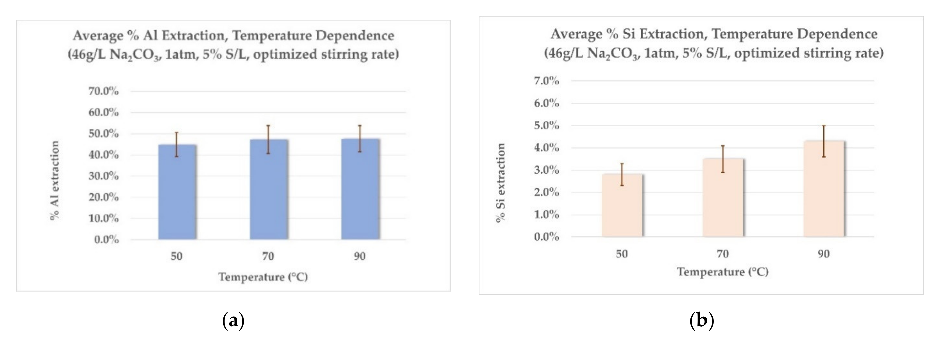
  • Effect of temperature on Al and Si extraction: As seen from Figure 5a, the extraction rate of Al remains virtually unaffected in the range between 70 °C and 90 °C, while the increase observed with a temperature raise from 50 °C to 70 °C is small. Si extraction rates (Figure 5b) increase with an increase in leaching temperature. The choice of high leaching temperatures would make sense only if higher Al extraction could also be achieved to counterbalance this phenomenon. For this reason, a temperature of 70 °C was chosen for the next two series of experiments, as the middle-ground between acceptable Al extraction rates and corresponding low Si co-dissolution rates.
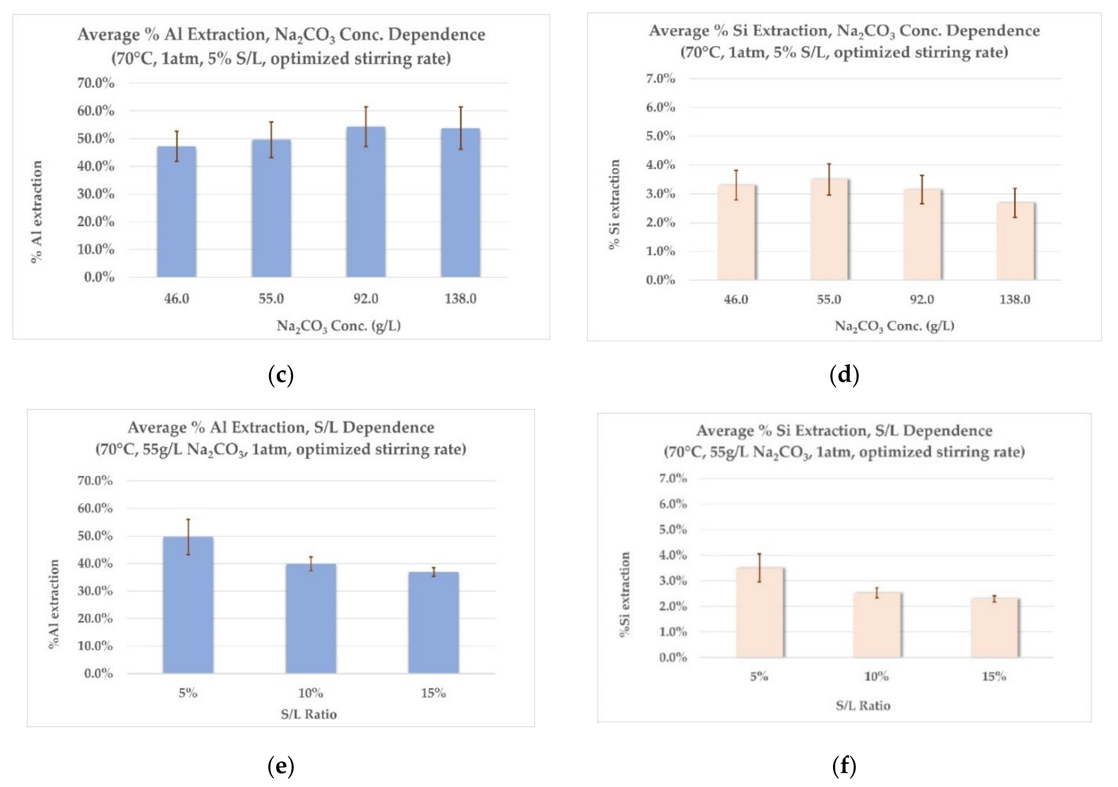
  • Effect of Na2CO3 concentration on Al and Si extraction: Employing a small excess of Na2CO3 (20% excess, 55 g/L) has practically the same effect on the Al extraction rate as employing a bigger excess (100% excess, 92 g/L), as shown in Figure 5c. Moreover, a larger excess of Na2CO3 (200% excess, 138 g/L) shows no further increase in Al extraction rates. As shown on Graph 5d, Si extraction rates remain constant throughout the range of Na2CO3 concentrations tested. This consistency could prove important for further modelling of the process in pilot scale. According to the results mentioned above, an excess of 20% Na2CO3 is selected for the last series of experiments.
  • Effect of S/L ratio on Al and Si extraction: As shown in Figure 5e,f, both Al and Si extraction rates are reduced with the increase in the S/L ratio. This was more or less expected, as with increased S/L ratio, the excess in concentration of the leaching agent is diminished (actually an excess of slag is employed). Consequently, this leads to lower Al and Si extraction rates and to more concentrated aluminate solutions, due to higher absolute amount of metals dissolved. Table 6 presents the concentration of Al and Si in the aluminate solution for each S/L ratio tested, calculated as equivalent Al2O3 and SiO2 concentrations, verifying the above explanations.
The results of the laboratory scale tests indicated overall low extraction rates for Al. Among the hydrometallurgical parameters tested, increasing the concentration of Na2CO3 showed to have a positive effect, but only for a small, controlled excess in relation to the stoichiometric amount needed. Moreover, Si extraction rates appear to be temperature-dependent, with the higher rates observed in 90 °C (Figure 5b) and remaining uniform in the range of 2–3% in 70 °C, regardless of the values of the other leaching parameters (Figure 5d,f). The optimum leaching conditions for 5% S/L ratio were achieved for leaching with a solution containing 55 g/L Na2CO3, at 70 °C, corresponding to ~50% of total extraction for Al and ~3.5% extraction for Si. The chemical analysis of the main components of the leaching residue is shown in Table 7 (dry basis).
In order to better comprehend the leaching mechanism, a final series of experiments was designed. They were termed “kinetic approach” tests and their goal was to monitor the evolution of Al and Si extraction rates during leaching. The corresponding leaching residues would be crystallographically analyzed in order to assess, through the solid products, the reactions taking place at different times. Consequently, the term “kinetic approach” is meant as a description of this experimental design and not a kinetic study of the hydrometallurgical system under investigation.

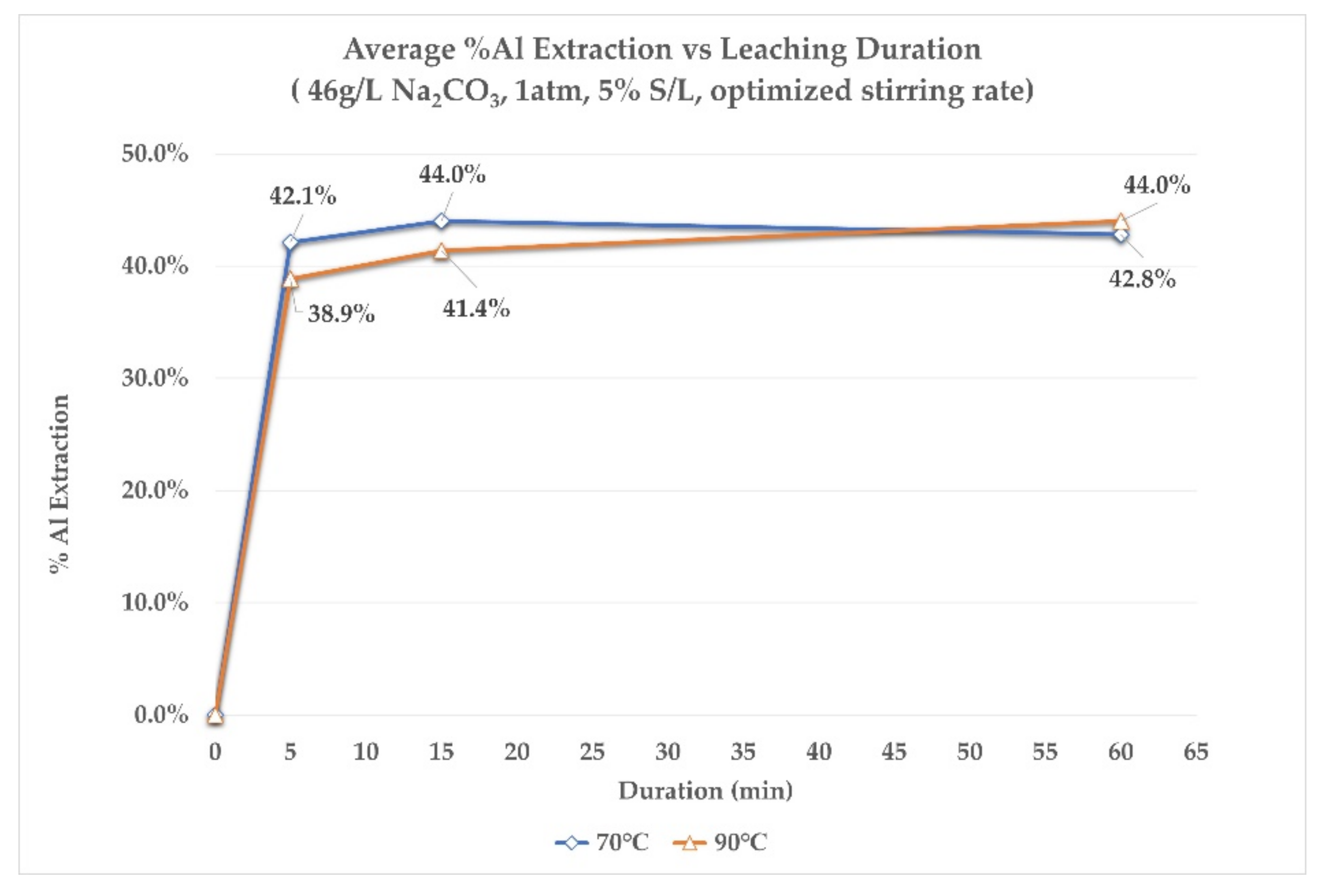
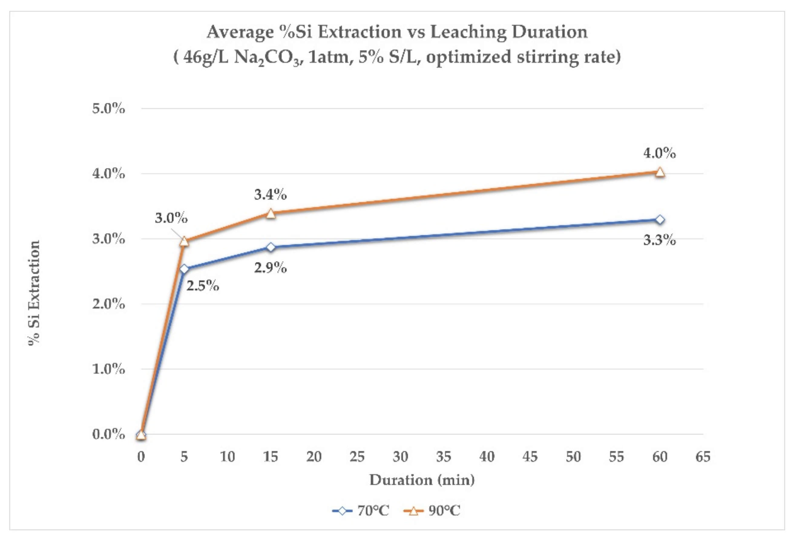
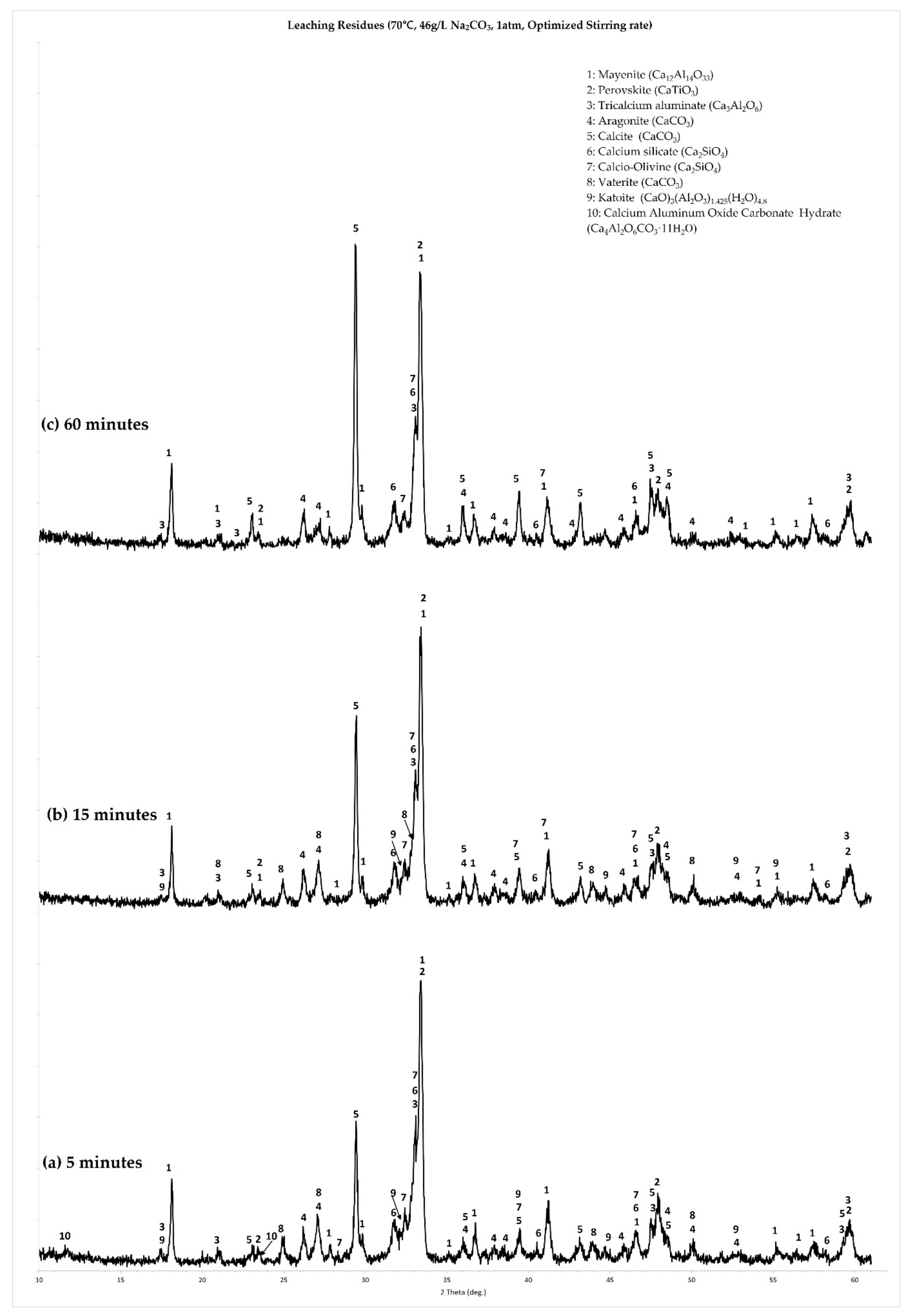
3.1.2. Kinetic Approach Tests

For these tests, the following values were selected for the parameters under investigation:
  • A 5% S/L ratio—this ratio was chosen to avoid excessive variations in the consumption of the leaching agent;
  • Na2CO3 concentration of 46 g/L, which corresponds to the theoretical amount needed for complete reaction between the CaO content of the slag and the carbonate content of the solution (according to Equation (1));
  • Tests were performed at 70 °C and 90 °C, in order to further assess the behavior of Si during leaching, which appears to be temperature-dependent.
First, the extraction rates of Al and Si, in relation to the leaching duration, for both temperatures, are presented, followed by the results of the crystallographic analysis of the leaching residues.
Figure 6 and Figure 7 present the % Al extraction and % Si extraction rates, at different leaching durations, for both temperatures studied. It is observed that no more than 15 min of leaching time is needed for Al and Si to reach their maximum extractions in the aluminate solution. Moreover, Al extraction appears to be slightly greater for the lower leaching temperature of 70 °C for the first 15 min of leaching. Finally, at the end of the leaching process, extraction rates for Al, at both temperatures, are almost equal. On the other hand, by looking at the extraction of Si, it is slightly greater at 90 °C during the whole duration of leaching. The final extraction rate of Si in both cases does not exceed 4%, which was also observed in the previous series of tests.
To summarize the main observations from the extraction rate results, it is shown that in the first 5 min of leaching, regardless of the leaching temperature, the rate of extraction is extremely rapid for aluminum. Practically, leaching comes to a standstill after the first 15 min of leaching. The crystallographic analysis of the residues at the first stages of leaching aims at providing more information about this behavior.
Figure 8a,c show the XRD graphs for the 70 °C tests at different leaching times (5 min, 15 min and 60 min tests, respectively). Figure 8a,b, corresponding to the residues obtained from the 5 min and 15 min tests, show many different reaction products and, consequently, a much more dynamic process during this stage of leaching. Residues of the 5 min leaching tests (Figure 8a) show that the formation of all three polymorphs of CaCO3 (calcite, vaterite and aragonite) has started, besides the presence of the unreacted slag phases (calcium aluminates, calcium silicates and perovskite). Moreover, two minor hydrate phases are present: katoite, with a chemical composition of (CaO)3(Al2O3)1.425(H2O)4.), which is a calcium aluminate hydrate phase, along with a calcium monocarboaluminate (Ca4Al2(OH)12CO3.5H2O).
With the progression of leaching, at 15 min duration (Figure 8b), the calcium monocarbonate aluminate phase is no longer observed, while katoite persists. At the same time the peaks of calcite intensify. Finally, after 60 min of leaching (Figure 8c), all hydrate phases, along with vaterite, are no longer observed. The main reaction products remaining are calcite and aragonite. The same succession of phenomena was observed also at the residues from the 90 °C leaching tests, the only difference being the persistence of the calcium monocarboaluminate phase in the residue of the 15 min leaching test.

3.1.3. Summary of Observations and Suggestions for the Pilot Work Tests

Laboratory scale work showed that significant optimizations were needed in order to increase the alumina yield of leaching. These optimizations were implemented in the design process of the planned pilot scale work. Concerning the issue of slag composition, the main observation, verified by the crystallographic analysis, was that the excess of CaO used to suppress C2AS formation has a negative effect on extraction, due to the formation of C3A. As a result, for the pilot scale pyrometallurgical work, the amount of CaO used as flux was reduced. This is reflected in the chemical (Table 3) and crystallographic composition (Figure 3) of the slag produced in pilot scale. This pilot scale slag contained about 36% CaO (compared to ~50% CaO of the laboratory scale slag). Some C2AS is formed, but the lowered CaO content favored the formation of CA.
Concerning the observations of the leaching tests, it was shown, first of all, that increased leaching temperatures and Na2CO3 concentrations are not needed for leaching calcium aluminate slags. Temperatures of 70 °C and a minor excess of Na2CO3 proved sufficient for extracting about 50% of the Al contained in the laboratory slag. Si co-dissolution is inevitable, though its extent appears to be easily predictable and temperature dependent. Moreover, it appears that maximum Al extraction is achieved fast (<20 min); as a result, depending on the pilot plants operative conditions, a leaching duration of less than 1 h is suggested. A key issue for pilot scale work is the fact that low S/L ratios are not desirable on operating and cost-effective grounds. According to these considerations, the conditions suggested for pilot plant work were as follows:
  • Concentration of leaching agent: 120 g/L Na2CO3 (corresponding to a small excess of Na2CO3 in relation to the CaO content of the slag);
  • S/L ratio: 10%;
  • Leaching temperature: 70 °C;
  • Duration: Less than 1 h (exact value defined by the operating capabilities of the pilot plant).

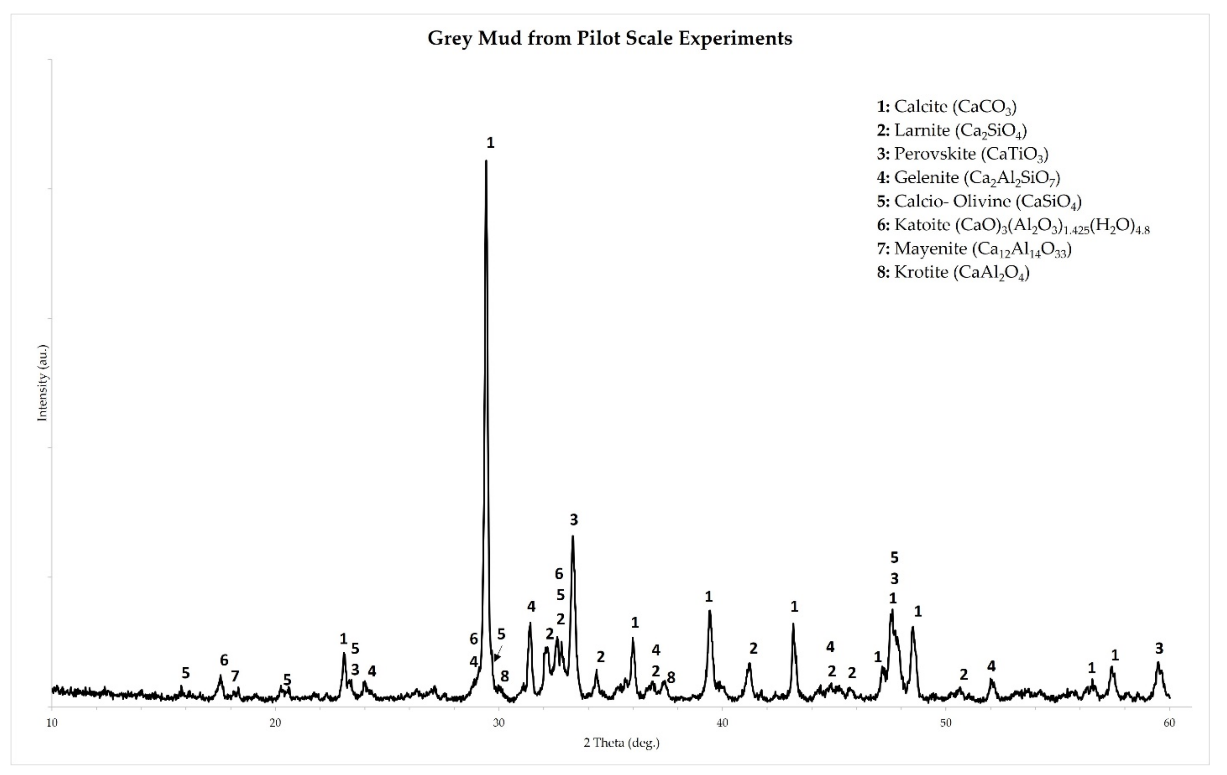
3.2. Results of Pilot Scale Experiments

As described earlier (Section 2.2), two leaching runs were performed, each with 150 kg of the calcium aluminate slag that was produced in the pilot scale EAF. Leaching and solid/liquid separation of a 150 kg of slag produced approximately 1380 L of aluminate solution and 114.9 kg of filtercake (grey mud), on a dry basis, in the first trial (Run A) and 1310 L of aluminate solution and 128.8 kg of grey mud, on a dry basis, in the second trial (Run B). The percent yield of grey mud in each run and the corresponding chemical analysis are shown in Table 8.
According to the data of Table 8, the leaching process achieved 72.08% and 64.56% aluminum extraction rates in the two tests, respectively, or 68.23% on average. Silicon extraction was limited to 1.95% and 1.85%, respectively, or 1.90% on average. The resulting aluminate solutions had 24.56 g/L and 23.65 g/L Al2O3 and will be used for alumina precipitation tests.
The crystallographic analysis of the grey mud produced in the pilot scale leaching runs is shown in Figure 9. The first observation is that C12A7 and CA are present only as minor phases in the residue, a fact that is related to the higher Al extraction rates achieved. Moreover, C2AS is still present in the residue as one of the main components, suggesting that the aluminum bound in this phase was not leached. Finally, a small fraction of the Al content of the slag is precipitated in the form of katoite. Even with the unleached C2AS and the precipitation of katoite, aluminum extraction rates were overall higher due to the incorporation of the suggestions based on the laboratory scale tests.

4. Discussion

Both laboratory and pilot scale work performed in the course of this research highlighted important aspects of the alkaline leaching of calcium aluminate slags. The most significant observations of the present work are discussed further in this section.

4.1. Correlation between Slag Composition and Aluminium Extraction Rates

The first important observation from the laboratory scale experiments was the low extraction rates for aluminum. Though the known effect of coating of the slag particles by CaCO3 is one of the reasons that further extraction is hindered [29], a closer examination to the XRD graphs of the residues elucidated that it was also the crystallographic composition of the slag that played a significant role. The slag used in the laboratory scale experiments was produced with an excess of CaO in order to dilute its SiO2 content and avoid the formation of C2AS. The excess CaO led to the formation of C3A, which proved less soluble under the conditions applied, as shown by its presence in the XRD graph of the leaching residue, even after 60 min of leaching (Figure 8c). This is also in accordance with the findings of previous researchers working with C3A produced by reagent grade raw materials [24,25]. In other words, the soluble alumina observed in the aluminate solutions is attributed mostly to the leaching of C12A7. This observation led to the decision of lowering the amount of CaO in the pilot scale.
As a consequence, the slag produced in pilot scale, was a mixture of C12A7 and CA, which were both easily leachable, even at higher S/L ratio and higher mean particle size, compared to the laboratory scale experiments. This can be observed in the XRD graph of the residue produced at the pilot scale leaching runs (Figure 9), where the intensities of characteristic diffraction peaks of C12A7 and CA have almost completely faded. Alumina extraction rates were on average 68%, compared to approximately 50% in the laboratory scale. Still, not all of the alumina was extracted and that can be attributed to the low leachability of the C2AS phase. This can be observed once more in the XRD graph of the pilot leaching residue (Figure 9), where the characteristic diffraction peaks of C2AS persist.
From the above analysis and the promising results from the pilot scale experiments, derived from the lowering of the CaO addition in the pyrometallurgical step, further optimization of the phase composition of the slag is needed in order to minimize its C2AS content while remaining in the C12A7/CA area of the phase diagram.

4.2. Comments on the Aluminium Extraction Mechanism

The kinetic approach tests further highlighted some important aspects of the leaching mechanism. Firstly, the accelerated leaching rates during the first 5 to 15 min of leaching. Secondly, the formation of calcium monocarboaluminate phase and of tricalcium aluminate hydrate (also referred to in literature as katoite, hydrogarnet, C3AH6, TCA) at the same time period of leaching. These observations need to be evaluated in the context of the leaching mechanism of calcium aluminate slags.

4.2.1. Effect of the Hydraulic Character of Calcium Aluminates

As stated earlier, the leaching of slags consisting of calcium aluminates with molar ratios of CaO/Al2O3 ≥ 1, has been described as a process that has two major outcomes, the production of CaCO3 and the dissolution of Al, according to the generic chemical Equation (1). Moreover, C3AH6 is regularly reported as a by-product and is considered a measure of Al losses, along with any unleached calcium aluminate phases [24,29]. This view of the process is rather simplistic as it considers that the only possible reactions during leaching are between (a) CaO and the CO32− ions, for the production of CaCO3, (b) between the calcium aluminates and water, for the production of C3AH6 and (c) between Na+ and Al(OH)4 ions, leading to the dissolution of the latter. This view does not incorporate the formation of the calcium monocarboaluminate phase observed in this work, nor does it adequately explain the rapid initial extraction rates. Consequently, a more detailed approach to explaining the chemical phenomena taking place is needed. The starting point for the discussion is the inherent physicochemical properties of the calcium aluminates.
A defining feature of the various calcium aluminates that is exploited in their applications as cementitious phases is their hydraulic character and their participation in hydration reactions. The products of these hydration reactions are various calcium aluminate hydrate phases. Since the hydrometallurgical process under examination involves the reaction of calcium aluminates in an aqueous phase, it is certain that their hydraulic character also affects their leaching behavior.
The hydration of any hydraulic phase is an irreversible process driven by the lower solubility of the hydrate phase formed, compared to the solubility of the solid being dissolved. Therefore, in such systems, a competition takes place between two equilibrium states that cannot be attained at the same time. The first one is the equilibrium between the superficially hydroxylated solid and the aqueous phase, which is the driving force for the dissolution ions from the solid phase to the solution. The second one is the equilibrium between the hydrates and the aqueous phase, which is the driving force for the precipitation of the hydrate phases. Put more simply, the competition between these two equilibrium states reflects the competing processes of dissolution of the hydraulic solids and precipitation of the hydrates [30].
The literature of hydration reactions of calcium aluminates and the properties of their solid products has been reviewed by H. Pöllmann [31]. The thermodynamically stable solid phases in the system Al2O3–CaO–H2O are C3AH6 and Al(OH)3 (also referred to as AH3 in the literature of cements). These phases do not crystallize immediately but form through the transformation of metastable hydrate phases, by a process termed as the “conversion reaction”. The formation of the metastable phases is temperature-dependent. Furthermore, the rate of the conversion reaction is accelerated at higher temperatures. These dependencies are shown in Equations (4)–(8), describing the hydration reactions of CA at intermediate and higher temperatures (Equations (4), (5) and (7)) and the corresponding conversion reactions (Equations (6) and (8)):
Intermediate temperatures (15 °C–25 °C)
3 CA +   H 2 O   excess CAH 10 + C 2 AH 8
2 CA + 11 H C 2 AH 8 + AH 3
2 CAH 10 C 2 AH 8 + AH 3 + 9 H
Higher temperatures (>25 °C)
3 CA + 12 H C 3 AH 6 + 2 AH 3
2 C 2 AH 8 2 C 3 AH 6 + AH 3 + 9 H
The hydration of C12A7 is analogous to that of CA, forming similar hydrates, the main difference being the formation of C2AH8 even at low temperatures, due to the higher CaO/Al2O3 in the phase [32,33]. The hydration of C3A, which is a constituent of the slag used in the laboratory scale experiments, follows a different path due to the value of the molar CaO/Al2O3 ratio of this compound [32,34]. The reaction describing the formation of the metastable hydrate phases during C3A hydration is described by Equation (9) and the corresponding conversion reaction is described by Equation (10):
2 C 3 A   +   H 2 O   excess C 2 AH 8 + C 4 AH 19
C 2 AH 8 + C 4 AH 19 2 C 3 AH 6 + 15 H
Most important to the present discussion is the description of the mechanism of hydration of calcium aluminate phases. The mechanism of hydration of all calcium aluminates is a “dissolution–precipitation” mechanism or “through solution” mechanism [32,35]. Though the mechanism applies to all basic calcium aluminate compounds, subtle differences exist between C3A and the other two calcium aluminates of interest to this study. First, the hydration of CA and C12A7 is briefly covered.
The moment CA (or C12A7) comes in contact with water or an aqueous solution, a hydroxylated surface layer forms, composed of Ca[Al(OH)4]2, also termed “superficially hydroxylated” calcium aluminate surface [30,36]. This surface dissolves in solution, exposing a fresh layer of anhydrous material, which in turn will be hydroxylated and dissolved. As a result of this process, relatively high concentrations of Ca2+ and Al(OH)4 ions are observed in the solution for a period of time before the precipitation of the hydrates takes place (induction period). When the solution reaches a supersaturation level, the metastable calcium aluminate hydrate phases will precipitate massively out of the solution. The degree of hydration of calcium aluminates can be increased by increasing the fineness of the anhydrous grains [37]. The conversion reaction of the metastable to stable phases also follows the same mechanism (“through solution”) and it initiates with the nucleation of the first C3AH6 [38]. The solubilities of the metastable hydrates are higher than the solubility of C3AH6 and the driving force of its precipitation is the dissolution of the metastable hydrates. Both metastable phases are more soluble in increased temperatures, which favors the progression of the conversion reaction for the production of C3AH6 and AH3 [31].
In the case of the C3A phase it has been observed that the first hydration products form an amorphous gel-like material, which then converts to the metastable phases according to Equation (9) [39]. Then, follows the conversion reaction as in the case of the other calcium aluminates. It can be observed that reaction (10) does not lead to the release of AH3 as is the case of the conversion reactions of CA and C12A7 (Equations (6) and (8)).
The hydration reactivity of calcium aluminates appears to be playing an important role also in the hydrometallurgical process of aluminum leaching from these phases, which takes place in an aqueous solution of Na2CO3. The dissociation of Na2CO3 in alkaline solutions can be presented according to Equation (11):
Na 2 CO 3 s 2 Na aq + + CO 3 aq 2
In the first minutes of leaching, high aluminum extraction rates are observed, which can be directly related to the dissolution mechanism described above. In more detail, and for the case of C12A7 and CA, the hydroxylated Ca[Al(OH)4]2 layer that forms as soon as the slag particles come in contact with the Na2CO3 aqueous solution will dissolve according to Equation (12).
Ca Al OH 4 2 Ca aq 2 + + 2 Al OH 4   aq
The leaching solution, having a considerable concentration in CO32−, will aid the dissolution process by consuming the Ca2+ ion initially dissolved, according to Equation (13) and consequently push the equilibrium of Equation (12) to the right.
Ca aq 2 + + CO 3   aq 2 CaCO 3 s
According to Equation (13), by continuously reducing the concentration of Ca2+ ions in solution, the solution is not allowed to reach supersaturation with respect to the metastable hydrates, at least in the initial stages of leaching, when the concentration of CO32− ions is at its highest value. At the same time, as CO32− ions are removed by the formation of CaCO3, the amount of free Na+ ions increases, causticizing the solution. A second outcome of this action is that more Al(OH)4 ions are allowed to remain in solution and not precipitate as Al(OH)3. In other words, the increase in free Na+ in solution pushes the equilibrium of the reaction described by Equation (14) to the side of the products.
Al OH 3 s + Na aq + + OH aq Al OH 4 aq + Na aq +
Thus, the high extraction rates at the first minutes of leaching are significantly aided by the inherent hydraulic properties of the leachable calcium aluminates (CA and C12A7). As mentioned earlier, the hydration of C3A is different due to the formation of the amorphous gel-like phase on the surface of C3A particles. It is probable that the lower extraction rates attributed to this phase are correlated to this phenomenon. Further research is needed to verify this suggestion.
The dissolution of the Ca[Al(OH)4]2 surface layer is not the only mechanism contributing to the extraction of aluminum and the causticization of the solution. Another reaction is certain to be taking place between the hydroxylated Ca[Al(OH)4]2 surface of the calcium aluminate phases and the solution. This reaction on the solid/liquid interface is the one leading to the surface precipitation of CaCO3 that has been described repeatedly in the literature. This action could be described by an equation such as (15).
Ca Al OH 4 2 +   CO 3   aq 2 CaCO 3 s + 2 Al OH 4   aq
At this point, Equation (15) must be treated as a conceptual reaction and not the actual description of the CaCO3 precipitation process, which is dealt with in the next section.
Consequently, the high extraction rates during the initial stages of leaching could be attributed to the combined effect of two actions. The first action is the aqueous dissolution of Ca2+ and Al(OH)4 ions from the hydroxylated surface of the calcium aluminates, which is an inherent property of the hydraulic character of these materials. The second action is a reaction on the solid/liquid interface, which leads to the surface precipitation of CaCO3. These two leaching actions are analogous to the competing dissolution and precipitation actions that characterize the CaO–Al2O3–H2O system. The dissolution action is accelerated by the presence of Na+ and CO32− ions of the leaching solution. Supersaturation of the solution in relation to the metastable calcium aluminate hydrates is not reached in the first stages of leaching due to the continuous reaction of the Ca+ and CO32− ions. At the same time, CaCO3 is precipitated, both through solution, according to Equation (13), and on the surface of the slag particles, according to an action resembling the one described by Equation (15). The latter is the one that is progressively hindering further dissolution and is discussed next.

4.2.2. CaCO3 Formation through Causticization of the Aluminate Solution

Equation (15) describes a conceptual action because it isolates the dissolved CO32− ions and does not take into consideration the remaining components of the solution. In reality, as a consequence of the rapid dissolution described earlier, the composition of the aqueous solution changes rapidly from a purely Na2CO3 solution to an Al(OH)4–NaOH–Na2CO3 solution. As a result, additional chemical reactions are possible between the dissolved Al(OH)4, Na+ and CO32− ions and the hydroxylated calcium aluminate surface. This group of reactions and the corresponding chemical system is already of interest to the alumina industry, with respect to the causticization of spent Bayer liquors. Consequently, studies of this system are relevant also to the leaching of calcium aluminates by aqueous Na2CO3 solutions.
Causticization is a process that aims at removing dissolved CO32− ions (expressed as equivalent Na2CO3) from the spent aluminate solution by its reaction with Ca(OH)2, according to the generic Equation (16).
Ca OH 2   s +   CO 3   aq 2 CaCO 3 s + 2 OH aq
The Al(OH)4 ions contained in the spent liquor are also known to react with lime to produce the C3AH6 phase, according to Equation (17):
3 Ca OH 2   s + 2 Al OH 4   aq Ca 3 Al 2 OH 12   s + 2 OH aq
The overall goal of causticization is the effective removal of the CO32− ions while minimizing aluminum precipitation as C3AH6. These are also the goals during the process of Na2CO3 leaching of the calcium aluminate slags, with the removal of the CO32− ions aiding the continuous dissolution of Ca2+ and Al(OH)4 ions from the hydroxylated surface of the calcium aluminate phases, and the resulting causticization allowing for increased concentration of Al(OH)4 ions in solution. On the other hand, reaction of the Al(OH)4 ions with the hydroxylated calcium aluminate surface might lead to a reaction analogous to Equation (17) and partial precipitation of the dissolved Al(OH)4. Therefore, a deeper look into the exact mechanism of causticization of aluminate solutions is needed.
The studies of G. I. D. Roach and S.P. Rosenberg et al. examined the chemical mechanism of Bayer causticization in more detail [40,41]. Both researchers identify quaternary intermediate phases such as the calcium monocarboaluminate (Ca4Al2(OH)12CO3.5H2O) as a critical to effective causticization.
In more detail, an aluminate solution in contact with lime will produce the monocarboaluminate phase according to the reaction described by Equation (18):
4 Ca OH 2   s + 2 Al OH 4   aq +   CO 3   aq 2 + 5 H 2 O Ca 4 Al 2 OH 12 CO 3 · 5 H 2 O s + 4 OH aq
This is an effective causticizing reaction but also removes the aluminum from the solution. In higher temperature (above 80 °C), the monocarboaluminate phase becomes unstable and reacts with CO32− ions to form CaCO3, according to Equation (19).
Ca 4 Al 2 OH 12 CO 3 · 5 H 2 O + 3 CO 3   aq 2   4 CaCO 3 s + 2 Al OH 4   aq + 4 OH aq + 5 H 2 O
This is considered the main causticization reaction leading to the precipitation of CaCO3, while at the same time increasing causticity and aluminum concentration in the solution. The reaction is written in equilibrium form because, upon cooling of a causticized liquor in contact with a pulp containing CaCO3, the so-called “reversion reaction” takes place and the calcium monocarboaluminate can reform [41]. The reversion reaction is obviously a reaction that also reduces the aluminum content in the solution.
In the present work, the identification of calcium monocarboaluminate in the residues of the initial stages of leaching is suggestive of a similar causticization process taking place. It was earlier suggested that the precipitation of CaCO3 on the surface of slag particles indicates that a reaction on the solid/liquid interface also takes place, besides the dissolution of Ca2+ and Al(OH)4. This reaction can now be further understood as a causticization reaction similar to (18), with the calcium sites of the hydroxylated calcium aluminate surface acting as a causticizing agent. As leaching is studied in temperatures over 70 °C, where the Equation (19) is favored, the surface precipitation of CaCO3 indicates efficient causticization and removal of aluminum from the hydroxylated calcium aluminate surface. Subsequently, the leaching/causticization action is gradually hindered and finally terminated when the coating of all slag particles with CaCO3 has been completed.
The formation of C3AH6 can also proceed via the monocarboaluminate according to the reaction described by Equation (20):
3 Ca 4 Al 2 OH 12 CO 3 · 5 H 2 O + 2 Al OH 4   aq + 4 OH aq 4 Ca 3 Al 2 OH 12   s +   3 CO 3   aq 2 + 5 H 2 O
This reaction is indicative of poor causticization and actually removes aluminum from the solution and it is favored by high Al(OH)4 and free NaOH concentration, and also hindered by high carbonate ion concentrations [40,41].
The fact that both the calcium monocarboaluminate phase and the C3AH6 are observed in the residues during the first 15 min of leaching could possibly be explained by the relative concentration of CO32− and Al(OH)4 ions. Specifically, the consumption of CO32− ions is high during the initial stages of leaching. A point is reached, depending on the initial Na2CO3 concentration of the leaching solution, that the relative concentration of CO32− ions, Al(OH)4 ions and free NaOH favors the Equation (20) instead of (19). This would suggest that an equilibrium between CaCO3 and C3AH6 exists and an excess of CO32− ions is always needed to avoid the action described by Equation (20). Further investigation will be performed in order to fully explain this phenomenon.

4.3. Comments the Silicon Co-Dissolution Phenomena

Both the laboratory and pilot scale tests showed that Si co-dissolution is inevitable, regardless of the slag composition, although lower extraction rates for Si were observed in the pilot scale (1.9% extraction rate compared to ~3.5% in laboratory scale). This phenomenon can be attributed to the presence of the difficult to leach C2AS phase. Consequently, in its present form, the leaching process must be followed by a desilication process in order to produce aluminate solutions of acceptable quality for the alumina industry.
Another aspect related to the Si chemistry of the leaching process under investigation is the probable Si removal action of C3AH being produced in the first stages of the leaching process. Pure C3AH is an end member of the hydrogrossular (HG) mineral series. In more detail, the HG series has a general chemical formula of Ca3Al2(SiO4)3-x(OH)4x; 0 ≤ x ≤3. Its structure is made up of AlO6 octahedra and SiO4 tetrahedra linked with oxygen and the hydroxyl component (OH). Si4+ is progressively replaced by 4H+ as x increases which leads to the formation of (OH)4 groups. Katoite is the name designated for HG with an x value in the range 1.5 < x ≤3 [42].
This substitution of 4H+ by Si4+ is what gives katoite a desilication potential. Jiongliang Yuan and Yi Zhang have already studied C3AH as desilication agent and found it to be superior for Si removal compared to lime [43]. The desilication action is described by the generic chemical Equation (21):
3 CaO · Al 2 O 3 · 6 H 2 O + k SiO 2 OH 2 2 3 CaO · Al 2 O 3 · k SiO 2 · 6 2 k H 2 O + 2 k OH + 2 k H 2 O
This action appears once again to be causticizing in nature and could also be contributing to the main causticization action (Equation (19)). Moreover, it is possible that the reduced Si co-dissolution rates observed during the pilot scale extraction tests could be attributed to this phases, which was observed in the crystallographic analysis of the residue (Figure 9). It is probable that further optimizations of the leaching process could incorporate this phenomenon in order to achieve the desired desilication of the solution.

5. Conclusions

Alkaline leaching with Na2CO3 aqueous solutions of calcium aluminate slags produced from the reductive smelting of Greek BR was studied in two interconnecting stages. In the first stage of the work, which was performed in laboratory scale, a slag produced in laboratory scale was tested in a series of hydrometallurgical tests. This material was prepared with excess of CaO as a flux in order to avoid the formation of C2AS which is unreactive in Na2CO3 solutions. The key parameters under investigation were the percent extraction rates of Al and Si from the slag. Analysis of the results of the laboratory scale tests highlighted several issues for further optimizations in the second stage of the work, the pilot scale extraction tests. The most important findings from both stages of this research are summarized below:
  • A calcium aluminate slag containing C12A7 and C3A, produced in laboratory scale, was leached in laboratory scale, under atmospheric pressure conditions. Leaching parameters tested were temperature, Na2CO3 concentration and S/L ratio, for optimized stirring rate. The extraction rates for Al were low under all conditions and at best a 54% Al extraction, in 5% S/L ratio was achieved. Laboratory scale work also highlighted high extraction rates for Al during the first 5 min of leaching, which progressively decelerate in the next 10 min, until no notable change in Al extraction is observed after that point.
  • For the design of the second stage of the work in pilot scale, the observations of the laboratory scale tests were utilized, suggesting a slag with a reduced amount of CaO and preferably containing a mixture of C12A7 and CA as the calcium aluminate phases. Moreover, leaching should be performed in moderate temperature (70 °C), for a short duration (<1 h) and with a Na2CO3 concentration not exceeding 120 g/L for a 10% S/L. The results of the pilot scale work confirmed the validity of the above suggestions, with alumina extraction reaching 68%, in 10% S/L ratio.
  • Si co-dissolution always occurred, both in the laboratory and the pilot scale experiments, at extraction rates of 3% and 1.9%, respectively. Desilication of the aluminate solution is needed.
  • Based on the results of laboratory leaching tests that were performed at 70 °C and 90 °C, for different leaching times (kinetic approach tests) the Al extraction mechanism was further explained. Al extraction rates observed are the net result of two mechanisms. The first is a mechanism of direct dissolution of Al into the solution, due to the hydraulic character of calcium aluminate phases. In an aqueous solution containing no other ions, dissolution would continue until supersaturation in relation to the metastable calcium aluminate hydrates. In the case of the aqueous Na2CO3 solutions, this supersaturation is not reached due to the reaction of CaCO3 formation through solution (Equation (12)). Moreover, the removal of CO32− ions from the solution increases the causticity (causticization) due to the increase in free Na+ ions, which in turn leads to an increase in dissolved Al(OH)4, as is observed in the first 5 min of leaching (Figure 6).
The second mechanism of Al extraction is a causticization mechanism that becomes progressively more dominant, as the concentration of Al(OH)4 in the solution increases. As in the case of spent Bayer liquor causticization, the present leaching solution containing Al(OH)4–NaOH–Na2CO3 reacts with the hydroxylated Ca sites on the slag particles producing calcium monocarboaluminate (Figure 8a), according to Equation (18). Subsequently, calcium monocarboaluminate reacts with the dissolved CO32− ions, further dissolving Al(OH)4 and at the same time precipitating CaCO3 on the surface of slag particles according to Equation (19). This action is responsible for the decelerating extraction rates, and after about 15 min of leaching, further extraction is ceased as the particles are completely coated with CaCO3.

Author Contributions

Conceptualization, M.V., E.B. and D.P.; methodology, E.B., P.D. and M.V.; software, M.V.; validation, M.V., E.B. and D.P.; formal analysis, M.V., E.G. and P.D.; investigation, A.B., E.B., P.D. and M.V.; resources, E.B. and D.P.; writing—original draft preparation, M.V. and E.B.; writing—review and editing, E.B., E.G., D.P.; visualization, M.V., E.B. and A.B.; supervision, E.B. and D.P.; project administration, M.V.; funding acquisition, E.B. and D.P. All authors have read and agreed to the published version of the manuscript.

Funding

Research funded from European Community’s Horizon2020 Programme REMOVAL (H2020/2014-2020/No.77646). This publication reflects only the authors’ view, exempting the Community from any liability.

Data Availability Statement

Data supporting research work can be found from M.V.

Acknowledgments

The authors would like to acknowledge the support of Alexandra Alexandri and Dimitrios Kotsanis, members of the Laboratory of Metallurgy of NTUA, who performed the chemical and crystallographic analyses of the samples presented in this work. All laboratory scale work was performed in the facilities and with the equipment of the Laboratory of Metallurgy of NTUA. The equipment for crystallographic analysis of solid samples was provided by the Hellenic Survey of Geology and Mineral Exploration (https://www.igme.gr/).

Conflicts of Interest

The authors declare no conflict of interest. The funders had no role in the design of the study; in the collection, analyses or interpretation of data; in the writing of the manuscript, or in the decision to publish the results.

References

  1. Ujaczki, E.; Feigl, V.; Molnar, M.; Cusack, P.; Curtin, T.; Courtney, R.; O’Donoghue, L.; Davris, P.; Hugi, C.; Evangelou, M.W.; et al. Re-using bauxite residues: Benefits beyond (critical raw) material recovery. J. Chem. Technol. Biotechnol. 2018, 93, 2498–2510. [Google Scholar] [CrossRef] [Green Version]
  2. Power, G.; Gräfe, M.; Klauber, C. Bauxite residue issues: I. Current management, disposal and storage practices. Hydrometallurgy 2011, 108, 33–45. [Google Scholar] [CrossRef]
  3. Balomenos, E.; Davris, P.; Pontikes, Y.; Panias, D. Mud2Metal: Lessons learned on the path for complete utilization of bauxite residue through industrial symbiosis. J. Sustain. Metall. 2016, 3, 551–560. [Google Scholar] [CrossRef]
  4. Alumina Production Statistics. Available online: https://www.world-aluminium.org/statistics/alumina-production (accessed on 20 June 2021).
  5. Klauber, C.; Gräfe, M.; Power, G. Bauxite residue issues: II. Options for residue utilization. Hydrometallurgy 2011, 108, 11–32. [Google Scholar] [CrossRef]
  6. REMOVAL Project. Available online: https://www.removal-project.com/ (accessed on 21 June 2021).
  7. Liu, X.; Han, Y.; He, F.; Gao, P.; Yuan, S. Characteristic, hazard and iron recovery technology of red mud—A critical review. J. Hazard. Mater. 2021, 420, 126542. [Google Scholar] [CrossRef]
  8. Valeev, D.; Zinoveev, D.; Kondratiev, A.; Lubyanoi, D.; Pankratov, D. Reductive smelting of neutralized red mud for iron recovery and produced pig iron for heat-resistant castings. Metals 2019, 10, 32. [Google Scholar] [CrossRef] [Green Version]
  9. Ochsenkuehn-Petropoulou, M.; Tsakanika, L.-A.; Lymperopoulou, T.; Ochsenkuehn, K.-M.; Hatzilyberis, K.; Georgiou, P.; Stergiopoulos, C.; Serifi, O.; Tsopelas, F. Efficiency of sulfuric acid on selective scandium leachability from bauxite residue. Metals 2018, 8, 915. [Google Scholar] [CrossRef] [Green Version]
  10. Borra, C.R.; Blanpain, B.; Pontikes, Y.; Binnemans, K.; Van Gerven, T. Recovery of rare earths and major metals from bauxite residue (red mud) by alkali roasting, smelting, and leaching. J. Sustain. Metall. 2016, 3, 393–404. [Google Scholar] [CrossRef]
  11. Rivera, R.M.; Xakalashe, B.; Ounoughene, G.; Binnemans, K.; Friedrich, B.; Van Gerven, T. Selective rare earth element extraction using high-pressure acid leaching of slags arising from the smelting of bauxite residue. Hydrometallurgy 2019, 184, 162–174. [Google Scholar] [CrossRef]
  12. Liu, Z.; Li, H. Metallurgical process for valuable elements recovery from red mud—A review. Hydrometallurgy 2015, 155, 29–43. [Google Scholar] [CrossRef]
  13. Zinoveev, D.; Pasechnik, L.; Fedotov, M.; Dyubanov, V.; Grudinsky, P.; Alpatov, A. Extraction of valuable elements from red mud with a focus on using liquid media—A review. Recycling 2021, 6, 38. [Google Scholar] [CrossRef]
  14. Borra, C.R.; Blanpain, B.; Pontikes, Y.; Binnemans, K.; Van Gerven, T. Recovery of rare earths and other valuable metals from bauxite residue (red mud): A review. J. Sustain. Metall. 2016, 2, 365–386. [Google Scholar] [CrossRef]
  15. Kaußen, F.M.; Friedrich, B. Phase characterization and thermochemical simulation of (landfilled) bauxite residue (“red mud”) in different alkaline processes optimized for aluminum recovery. Hydrometallurgy 2018, 176, 49–61. [Google Scholar] [CrossRef]
  16. Kaußen, F.M.; Friedrich, B. Methods for alkaline recovery of aluminum from bauxite residue. J. Sustain. Metall. 2016, 2, 353–364. [Google Scholar] [CrossRef] [Green Version]
  17. Wilding, M.C. Aluminates. In Ceramic and Glass Materials: Structure, Properties and Processing; Shackelford, J.F., Doremus, R.H., Eds.; Springer US: Boston, MA, USA, 2008; pp. 49–70. [Google Scholar]
  18. Hallstedl, B. Assessment of the CaO-Al2O3 system. J. Am. Ceram. Soc. 1990, 73, 15–23. [Google Scholar] [CrossRef]
  19. Jerebtsov, D.A.; Mikhailov, G.G. Phase diagram of CaO-Al2O3 system. Ceram. Int. 2001, 27, 25–28. [Google Scholar] [CrossRef]
  20. Miller, J.; Irgens, A. Alumina production by the pedersen process—History and future. In Essential Readings in Light Metals: Volume 1 Alumina and Bauxite; Donaldson, D., Raahauge, B.E., Eds.; Springer International Publishing: Cham, Germany, 2016; pp. 977–982. [Google Scholar]
  21. Chou, K.S.B.G. Formation of calcium aluminates in the lime-sinter process part II. Kinetic study. Cem. Concr. Res. 1981, 11, 167–174. [Google Scholar] [CrossRef]
  22. Tian, Y.; Pan, X.; Yu, H.; Han, Y.; Tu, G.; Bi, S. An improved lime sinter process to produce Al2O3 from low-grade Al-containing resources. In Light Metals 2016; Williams, E., Ed.; Springer International Publishing: Cham, Germany, 2016; pp. 5–9. [Google Scholar]
  23. Lundquist, R.V.; Leitch, H. Solubility Characteristics of Monocalcium Aluminate, 6294; Bureau of Mines: Washington, DC, USA, 1963.
  24. Lundquist, R.V. Aluminum Extraction Characteristics of Three Calcium Aluminates in Water, Sodium Hydroxide, and Sodium Carbonate Solutions, 6528; Bureau of Mines: Washington, DC, USA, 1964.
  25. Azof, F.I.; Kolbeinsen, L.; Safarian, J. The leachability of calcium aluminate phases in slags for the extraction of alumina. In Proceedings of the 35th International ICSOBA Conference, Hamburg, Germany, 2–5 October 2017; pp. 243–254. [Google Scholar]
  26. Kim, Y.J.; Nettleship, I.; Kriven, W.M. Phase transformations in dicalcium silicate: II, TEM studies of crystallography, microstructure, and mechanisms. J. Am. Ceram. Soc. 1992, 75, 2407–2419. [Google Scholar] [CrossRef]
  27. Nielsen, K. The pedersen process—A old process in a new light. Erzmetall 1978, 31, 523–525. [Google Scholar]
  28. Vafeias, M.; Bagani, M.; Xakalashe, B.; Balomenos, E.; Panias, D.; Friedrich, B. Alkaline alumina recovery from bauxite residue slags. In Proceedings of the 3rd International Bauxite Residue Valorisation and Best Practices Conference, Virtual Conference, Online, 29 September–1 October 2020; pp. 55–62. [Google Scholar]
  29. Azof, F.I.; Vafeias, M.; Panias, D.; Safarian, J. The leachability of a ternary CaO-Al2O3-SiO2 slag produced from smelting-reduction of low-grade bauxite for alumina recovery. Hydrometallurgy 2020, 191, 105184. [Google Scholar] [CrossRef]
  30. Damidot, D.; Sorrentino, D.; Guinot, D. Factors influencing the nucleation and growth of the hydrates in cementitious systems: An experimental approach. In Proceedings of the 2nd International RILEM Symposium on Hydration and Setting, Dijon, France, 11–13 June 1997. [Google Scholar]
  31. Pöllmann, H. Calcium aluminate cements—Raw materials, differences, hydration and properties. Rev. Mineral. Geochem. 2012, 74, 1–82. [Google Scholar] [CrossRef]
  32. Scrivener, K.L.; Capmas, A. 13—Calcium aluminate cements. In Lea’s Chemistry of Cement and Concrete, 4th ed.; Hewlett, P.C., Ed.; Butterworth-Heinemann: Oxford, UK, 1998; pp. 713–782. [Google Scholar]
  33. Edmonds, R.N.; Majumdar, A.J. The hydration of 12CaO·7A12O3 at different temperatures. Cem. Concr. Res. 1988, 18, 473–478. [Google Scholar] [CrossRef]
  34. Christensen, A.N.; Jensen, T.R.; Scarlett, N.V.Y.; Madsen, I.C.; Hanson, J.C. Hydrolysis of pure and sodium substituted calcium aluminates and cement clinker components investigated by in situ synchrotron X-ray powder diffraction. J. Am. Ceram. Soc. 2004, 87, 1488–1493. [Google Scholar] [CrossRef]
  35. Lamour, V.H.R.; Monteiro, P.J.M.; Scrivener, K.L.; Fryda, H. Microscopic studies of the early hydration of calcium aluminate cements mikroskopische untersuchungen von frisch abgebundenem calziumaluminatzement. In Proceedings of the Calcium Aluminate Cements (CAC), International Conference on Calcium Aluminate Cements, London, UK, 16–19 July 2001; pp. 169–180. [Google Scholar]
  36. Adams, M.P. Factors Influencing Conversion and Volume Stability in Calcium Aluminate Cement Systems. Ph.D. Thesis, Oregon State University, Corvallis, OR, USA, 28 May 2015. [Google Scholar]
  37. Klaus, S.R.; Neubauer, J.; Goetz-Neunhoeffer, F. How to increase the hydration degree of CA—The influence of CA particle fineness. Cem. Concr. Res. 2015, 67, 11–20. [Google Scholar] [CrossRef]
  38. Taylor, H.F.W. 10 Calcium aluminate, expansive and other cements. In Cement Chemistry, 2nd ed.; Thomas Telford Publishing: London, UK, 1997; pp. 295–322. [Google Scholar]
  39. Odler, I. 6-Hydration, setting and hardening of portland cement. In Lea’s Chemistry of Cement and Concrete, 4th ed.; Hewlett, P.C., Ed.; Butterworth-Heinemann: Oxford, UK, 1998; pp. 270–326. [Google Scholar]
  40. Roach, G.I.D. The equilibrium approach to causticisation for optimising liquor causticisity. In Essential Readings in Light Metals: Volume 1 Alumina and Bauxite; Donaldson, D., Raahauge, B.E., Eds.; Springer International Publishing: Cham, Germany, 2016; pp. 228–234. [Google Scholar]
  41. Rosenberg, S.P.; Wilson, D.J.; Heath, C.A. Some aspects of calcium chemistry in the bayer process. In Essential Readings in Light Metals: Volume 1 Alumina and Bauxite; Donaldson, D., Raahauge, B.E., Eds.; Springer International Publishing: Cham, Germany, 2016; pp. 210–216. [Google Scholar]
  42. Adhikari, P.; Dharmawardhana, C.C.; Ching, W.-Y. Structure and properties of hydrogrossular mineral series. J. Am. Ceram. Soc. 2017, 100, 4317–4330. [Google Scholar] [CrossRef]
  43. Yuan, J.; Zhang, Y. Desiliconization reaction in sodium aluminate solution by adding tricalcium hydroaluminate. Hydrometallurgy 2009, 95, 166–169. [Google Scholar] [CrossRef]
Figure 1. Conceptual flowsheet of the metallurgical process for the treatment of BR under investigation in the present work.
Minerals 11 00896 g001
Figure 2. Particle size distribution and corresponding graphical estimation of the D50 of the Ca-rich slag used for the laboratory scale experiments of this study.
Minerals 11 00896 g002
Figure 3. Powder X-ray Diffractogram and phase identification of the Ca-rich slag used for the laboratory scale experiments of this study.
Minerals 11 00896 g003
Figure 4. Powder X-ray Diffractogram and phase identification of the Ca-rich slag used for the pilot scale experiments of this study.
Minerals 11 00896 g004
Figure 5. Laboratory scale extraction results: (a) effect of temperature on Al extraction, (b) effect of temperature on Si extraction, (c) effect of Na2CO3 concentration on Al extraction, (d) effect of Na2CO3 concentration on Si extraction, (e) effect of S/L ratio on Al extraction, (f) effect of S/L ratio on Si extraction.
Minerals 11 00896 g005aMinerals 11 00896 g005b
Figure 6. The %Al extraction rate at different leaching times, at 70 °C and 90 °C.
Minerals 11 00896 g006
Figure 7. The %Si extraction rate at different leaching times, at 70 °C and 90 °C.
Minerals 11 00896 g007
Figure 8. Crystallographic characterization of XRD analysis of leaching residues of the kinetic approach experiments at 70 °C: (a) residue of 5 min leaching test, (b) residue of 15 min leaching test and (c) residue of 60 min leaching test.
Minerals 11 00896 g008
Figure 9. Powder X-ray Diffractogram and phase identification of the grey mud produced at the pilot scale leaching experiments of this study.
Minerals 11 00896 g009
Table 1. Parameters tested in the laboratory scale tests, their range, levels and corresponding values selected.
ParameterRangeLevelsParameter Values Tested
Temperature50–90 °C350°, 70°, 90°
Na2CO3 concentration46–138 g/L446 g/L, 55 g/L, 92 g/L, 138 g/L
S/L Ratio5–15%35%, 10%, 15%
Table 2. Chemical analysis of the Ca-rich slag used for the laboratory scale experiments of this study.
ComponentCaOAl2O3SiO2TiO2FeONa2OMgOCr2O3COthers
Content50.8%26.3%10.4%5.7%1.2%2.4%0.8%0.11%1.7%0.7%
Table 3. Chemical analysis of the materials used in pilot scale pyrometallurgical tests.
MaterialAl2O3 %Fe2O3%CaO %SiO2 %TiO2 %Na2O %MgO %CaCO3 %C
%
S
%
P
%
LOI
%
Others
%
BR19.7542.749.426.985.282.92-----9.423.44
Lime--96.37---0.630.93----2.07
Coke3.11-1.283.74----82.620.220.04-8.99
Table 4. Chemical analysis of the Ca-rich slag produced and used for the pilot scale experiments of this study.
ComponentAl2O3 %Fe2O3%CaO %SiO2 %TiO2 %Na2O %V2O5 %SO3 %LOI %Others
Content32.000.8936.3013.104.281.380.080.611.579.79
Table 5. Al and Si extraction rates in the washing solutions of the laboratory scale tests.
Parameter TestedParameter Value% Al Extraction in
Washing Solution
% Si Extraction in
Washing Solution
Temperature50 °C1.6%0.6%
70 °C1.9%0.5%
90 °C2.3%0.4%
Na2CO3 Conc.46 g/L1.9%0.5%
55 g/L1.6%0.4%
92 g/L2.3%0.4%
138 g/L1.7%0.3%
S/L Ratio5%2.3%0.4%
10%2.7%0.3%
15%3.3%0.3%
Table 6. Al and Si extraction rates and concentrations in the aluminate solutions at different S/L ratios.
S/L Ratio% Al Extraction% Si ExtractionAl2O3 (g/L)SiO2 (g/L)
5%49.7%3.5%6.50.18
10%39.9%2.5%10.40.26
15%36.9%2.3%15.60.36
Table 7. Chemical analysis of the grey mud (dry basis) produced under the optimal conditions of the laboratory scale experiments of this study (5% S/L, leaching with 55 g/L Na2CO3, at 70 °C).
ComponentCaOAl2O3SiO2TiO2FeONa2OOthersLOI
Content51.1%13.8%9.3%5.9%1.4%0.8%1.9%15.8%
Table 8. Percent yield and corresponding chemical analysis of the produced filtercakes (grey muds) from the pilot scale tests.
Material
on Dry
Basis
Yield %Al2O3 %Fe2O3 %CaO %SiO2 %TiO2 %Na2O %V2O5 %SO3 %LOI %
Grey Mud (Run A)76.6%10.501.9745.9011.806.155.370.140.2616.70
Grey Mud (Run B) 85.8%9.052.0442.9011.605.185.810.080.2421.90
Publisher’s Note: MDPI stays neutral with regard to jurisdictional claims in published maps and institutional affiliations.

