Article

The Recent Progress China Has Made in the Backfill Mining Method, Part II: The Composition and Typical Examples of Backfill Systems

School of Resources and Safety Engineering, Central South University, Changsha 410083, China
*
Author to whom correspondence should be addressed.
Minerals 2021, 11(12), 1362; https://doi.org/10.3390/min11121362
Submission received: 14 November 2021 / Revised: 28 November 2021 / Accepted: 30 November 2021 / Published: 2 December 2021
(This article belongs to the Special Issue Backfilling Materials for Underground Mining, Volume II)

Abstract

:
The backfill mining method is a widely used mining method in the major mines of China, which can maximize the recovery of mineral resources and protect the environment. Currently, major mines in China are starting to build backfill systems to apply the backfill mining method, therefore, Part II reviews the progress China has made on creating backfill systems, of which the main contents include: (1) Composition of the backfill system common in Chinese mines; (2) Typical examples of the backfill system in China. Finally, Part II serves as a guide to begin a conversation, and to encourage experts and scholars to engage in the research of this field.

1. Introduction

The backfill (filling) mining method is one of the earliest methods adopted by the metal and coal mines, as it can maximize the recovery of underground mineral resources, protect the surface environment, and the surface buildings [1].
In recent years, with the progress in backfill materials, backfill technology, and pipeline conveying technology and equipment, the cost of backfill has been consistently reduced, especially because of national attention to safety and environmental protection. Because of its advantages, the backfill mining method has been widely used in coal mines, iron mines, chemical areas, and others [1,2].
The key to the backfill mining method lies in the backfill technology and backfill systems. The backfill system constructed by the mine not only needs to simultaneously meet the needs of backfill mining, goaf treatment, tailings disposal, and recovery of high-grade residual ore, but it also needs to meet the high standard of “reliable operation, matching capacity, low operating cost and controllable investment” which is China’s requirement for mining production. Moreover, the backfill system construction should move through experimental research and theoretical analysis, scheme comparisons, backfill aggregate for the pipeline, and the backfill ratio of key technical parameters, such as determination of the cost of the backfill process scheme, selection of an appropriate backfill site and its preparation, assurance of the reliability of the backfill system and the control of the backfill cost, in order to reduce investment costs and operating costs [3,4].
Part I of this series interpreted the theory and equipment of filling slurry pipeline transportation and introduced the experience Chinese researchers have accumulated in the exploration of backfill mining, therefore, Part II details for the readers China’s mining industry, with attention to two aspects:
(1)
The common composition of backfill systems in Chinese mines; and
(2)
Typical examples of backfill systems in China.

2. Common Composition of Backfill Systems in Chinese Mines

2.1. General Introduction

At present, the newly built and in-use backfill system in China is generally composed of three relatively independent parts: material preparation and storage system, backfill slurry preparation system, and pipeline conveying system [5].

2.1.1. Material Preparation and Storage System

According to the different sources and properties of the backfill aggregate, the preparation and storage systems of the materials in the early stages are also different.
Grading tailings backfill (filling) generally means that coarse-grained particles in the entire tailings are used as backfill aggregate to fill the goaf, and fine-grained particles are discharged to the tailings reservoir. The main technological process of material preparation and storage system in the early stage is as follows: the cyclone group is used to swirl and classify the whole tail mortar body produced by the dressing plant, the fine particle size overflow is directly discharged to the tailings reservoir, and the coarse particle size bottom flow is further dehydrated to the filter cake state by a ceramic filter and then discharged into the storage yard. In recent years, a new type of graded tailings backfill system has emerged, which uses the fine particle size as backfill aggregate to fill the goaf and coarse particle size as a construction aggregate for secondary use. The main process of material preparation and the storage system in the early stage is as follows: a high frequency vibration dehydration screen is used to classify the whole tail mortar body produced by the dressing plant. The moisture content of the coarse particle size on the screen is generally lower than 18%, which can be directly reused as building materials. Under the sieve, fine particle size tail mortar is added to the thickener to further concentrate the paste/paste state [6].
The material preparation and storage system of the whole tailings backfill system is relatively simple. Usually, the whole tailings mortar body produced by the concentrator is directly transported to the vertical sand bin or deep cone thickener, and the clear overflow water and high concentration of bottom flow can be obtained by adding flocculent. Therefore, tailings flocculation, settlement, and concentration are the foremost technological links of the material preparation and storage system of the full tailings backfill system. The core equipment is a vertical sand silo or deep cone thickener, and the obtained high concentration bottom flow is directly stored temporarily in the vertical sand silo or deep cone thickener [7].

2.1.2. Backfill Slurry Preparation System

The backfill slurry preparation system refers to the preparation of qualified backfill slurry by accurate measurement, stable feeding, and uniform mixing of the backfill aggregate produced by the material preparation and storage system in the early stage and the cementing material and water in accordance with a certain proportion of mixing. Therefore, the main process of backfill slurry preparation system is: measurement, feeding, and mixing [8,9].
(1)
Measurement Device
Coinciding with the different moisture content of the backfill aggregate produced by the material preparation and storage system in the early stage, the metering devices used are also different. The high concentration bottom flow produced by the vertical sand silo or deep cone thickener is primarily measured by a flowmeter and a concentration meter. Dry aggregate and tailings dehydrated to filter cake state are generally unloaded to the bin by a forklift, the vibrating ore drawing machine is set at the bottom of the bin to release the material evenly, and then the belt scale is used for measurement.
(2)
Feeding Device
The high concentration bottom flow produced by the vertical sand silo or deep cone thickener is generally pumped to the mixing drum directly through pipe self-flow or the shear pump. Dry aggregate and tailings dehydrated to filter cake state are generally weighed by the belt and then loaded into the stirring drum. Cementing materials are generally stored in the finished cement warehouse, the screw conveyor has a frequency conversion speed regulation device, in order to adjust the amount of feed according to the need, and the screw weighing feeder feeds, by the metering on the mixing bucket. Backfill water is generally added to adjust the concentration when the concentration of backfill slurry is too high. Usually, clear water in the high tank or the overflow pool is used to control the feed amount by the flow meter.
(3)
Stirring Device
The backfill aggregate and cementitious materials need to be fully stirred and mixed through the mixing system to form qualified backfill slurry, so slurry mixing is one of the key links in the backfill preparation system. Considering that in practical use, the solid particles and water in the backfill easily agglomerate, the core of the fragile agglomeration adheres to the periphery of a layer of cement slurry and is not easy to pound. The pipeline transportation performance and backfill effect of the backfill slurry are closely related to the mixing quality of the slurry, and it is necessary to ensure that all materials are fully mixed and evenly stirred in the mixing system. At present, the commonly used mixing devices for the preparation of mine backfill slurry mainly include a mixing barrel and horizontal double-shaft mixer [10].

2.1.3. Pipeline Delivery System

Modern backfill technology uses hydraulic transport instead of mechanical or pneumatic, the modern backfill technology uses water as the main transport carrier to transport the backfill aggregate and cementing materials to the goaf through pipes. Pipeline transportation of backfill slurry has many advantages such as good continuity, large conveying capacity, low energy consumption, and a high degree of automation. Most mines are connected with the main shaft and roadway through the construction of vertical backfill boreholes in the backfill station (deviation slope controlled within 5‰), and a small number of mines are directly connected with the main development shaft and roadway by laying backfill pipes on the surface [11]. According to the size of backfill line n, the pipeline conveying system can be divided into artesian conveying (n < 6) and pumping (n ≥ 6) types. Among them, self-flow transportation, namely the backfill slurry, can overcome the resistance loss along the pipeline under its own gravity and flow to the goaf; pumping backfill requires towing pump or backfill industrial pump to provide additional pressure to transport the backfill slurry to the goaf. Referring to the experience of backfill mines at home and abroad, taking into account capacity, transportation reliability and slurry outlet pressure, the economic velocity of pumping filled slurry is generally about 1.5–1.8 m/s, and that of self-flow transportation is generally about 2.8–3.5 m/s [12].

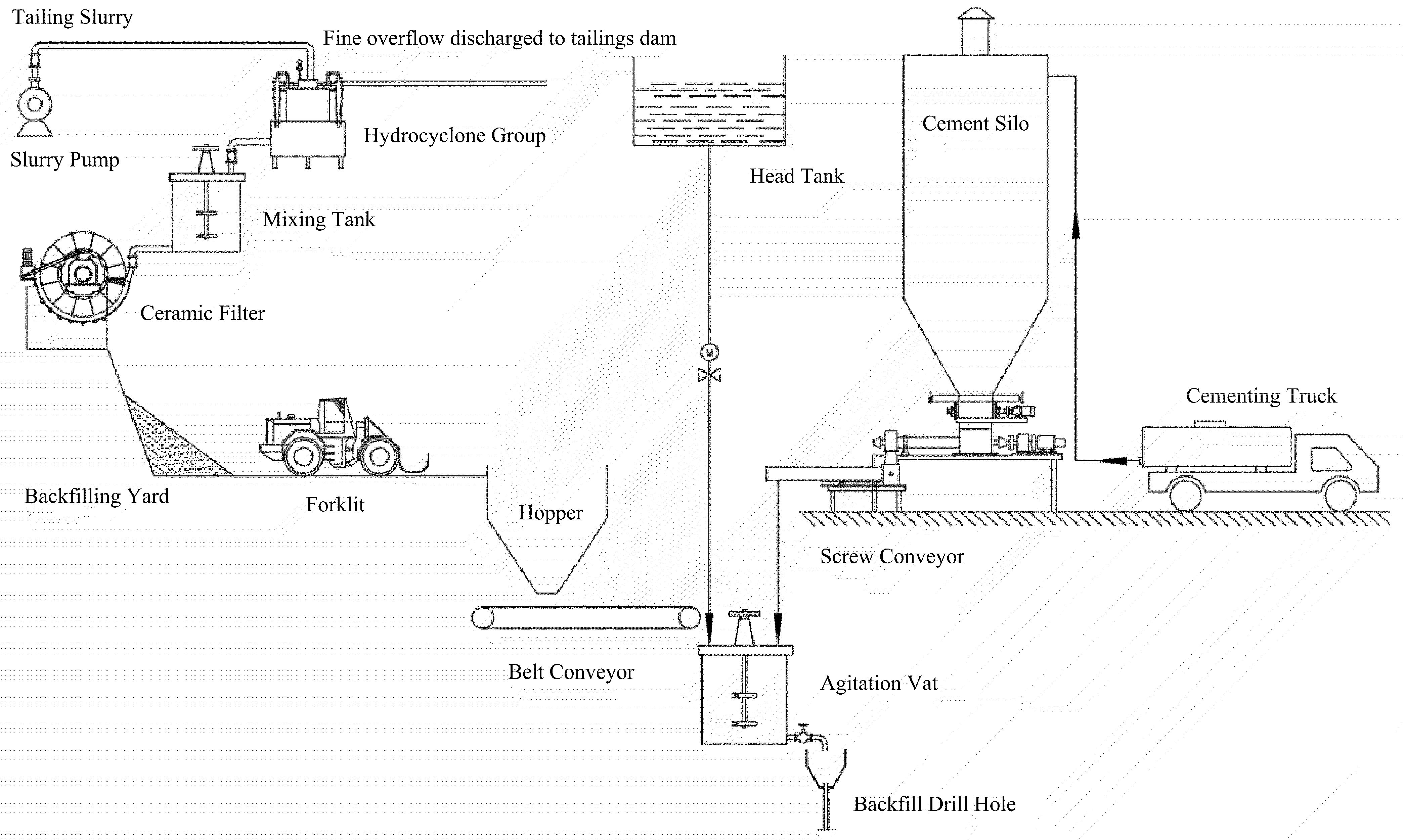
2.2. Graded Tailings Backfill System

Although the earliest water–sand backfill and waste rock backfill were simple, the backfill body strength was low and the backfill effect was poor. With the continuous progress of backfill technology, it has been gradually replaced by the more economical and efficient tailings cemented backfill technology. Since the 1980s, the process and technology of graded tailing backfill have been rapidly popularized and applied in more than 60 non-ferrous, coal, and gold mines, such as the An-qing Copper Mine, the Zhang-ma-tun Iron Mine, and the San-shan-dao gold mine. Grading tailings backfill generally means that coarse-grained particles in the whole tailings are used as backfill aggregate to fill the goaf, and fine-grained particles are discharged to the tailings reservoir [13,14].

2.2.1. Process Flow of Coarse Particle Size Grading Tailings Backfill System

As shown in Figure 1, the full-tail mortar body with a mass concentration of about 20% produced by the concentrator is pumped to the hydrocyclone group at the top of the backfill station through the slurry pump. Under the action of the centrifugal force of the hydrocyclone group, coarse particle size tailings and fine particle size tailings are centrifuged and classified successively by density difference. The fine particle composition (about 30–50%) and water overflow from the upper part of the cyclone and are discharged into the tailings dam through the slurry pump. Coarse particles (about 50–70%) are discharged as the bottom flow.
The mass concentration of the bottom flow can generally reach 40–50%, and the tailing cake with water content below 20% can be used for backfill after further dehydration by the ceramic filter. Coarse particle tailing cake is unloaded from the ceramic filter to the yard for temporary storage (the yard volume should meet the 2–3 days amount of backfill aggregate). During the backfill process, the coarse particle tailing cake is loaded into the unloading hopper by the forklift, and then released by the vibrating ore drawing machine at the bottom of the unloading hopper. After being measured by the belt scale, it is conveyed to the agitation vat by the belt conveyor. The cementing material is generally stored in the finished cement warehouse (the volume of the warehouse body should meet the amount of cementing material of 2–3 days), and the screw conveyor at the bottom of the warehouse (including the screw feeder and spiral electronic scale) measures the feeding to the agitation vat according to the backfill ratio requirements. The backfill water can be defiltered by the head tank or the ceramic filter, and the coarse particle size tailings, cementitious material, and water can be fully stirred in the agitation vat according to a certain backfill ratio, to prepare the qualified backfill slurry, and then transported to each middle section to be filled by backfill drill hole and underground pipeline [14,15].

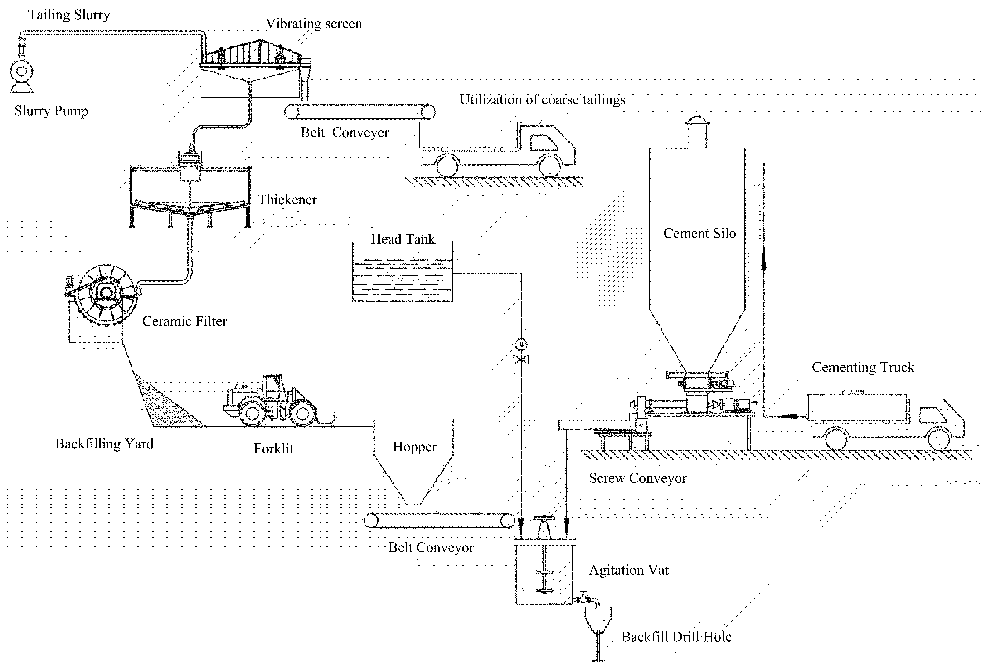
2.2.2. Process Flow of Fine Particle Size Grading Tailings Backfill System

As shown in Figure 2, the full-tail mortar body with a mass concentration of about 20% generated by the concentrator is pumped to the vibration screen at the top of the backfill station through the slurry pump. Under the action of vibration screen, coarse and fine particle size tailings are classified by the difference in particle size. The moisture content of the coarse particle size on the screen is generally less than 20%, which can be slid into the backfilling yard for temporary storage and reused as construction aggregate or aerated concrete bricks [14,15,16].
The rest of the process is the same as in the Section 2.2.1.

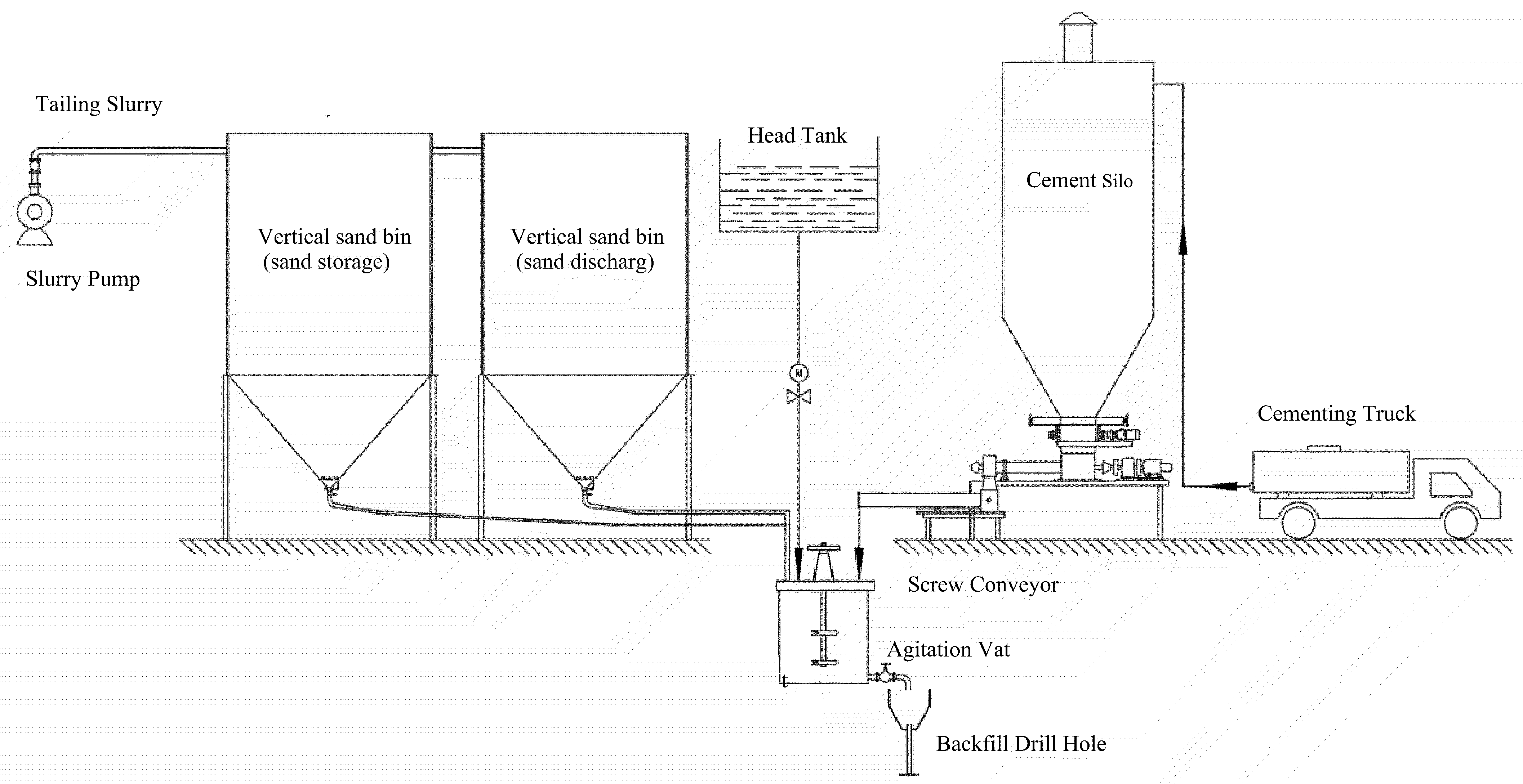
2.3. Full Tailings Backfill System

As early as the 1990s, China carried out key experimental research on the cemented backfill technology of high concentration (weight concentration of 78%) in Jinchuan Company and Fankou Lead-zinc Mines, respectively. After 2000, full tailings backfill completely replaced graded tailings backfill and was widely used in mines. Depending on the key equipment of tailings concentration and dehydration (the vertical sand silo or deep cone thickener), the corresponding full tailings backfill system is slightly different [17].

2.3.1. Process Flow of Vertical Sand Silo Backfill System

Before 2010, the newly built full tailings backfill system mainly took the vertical sand bin as the core tailings concentration and storage equipment. In order to prevent the bottom of the sand silo from hardening and blocking the sand discharge mouth, the pulping method was usually used to ensure the sand discharge effect of the vertical sand silo and reduce the blockage of flow. At the same time, it was generally necessary to build two vertical sand silos, one for material storage and one for discharge to ensure the continuity of backfill. As shown in Figure 3, the full-tail mortar body with a mass concentration of about 20% generated by the concentrator is pumped to the vertical sand bin of the backfill station by the slurry pump. Under the action of the flocculent, the sedimentation rate of fine particle size in the full-tail sand is greatly accelerated, and the high-concentration bottom flow and clarified overflow water with a bottom flow concentration of 50–60% can be obtained.
The high concentration bottom flow of vertical sand silo is fully stirred with water and cementitious materials in the mixing bucket according to a certain backfill ratio, and the qualified backfill slurry is prepared and then transported to the area to be filled in each middle section by the backfill drill hole and the underground pipeline [18,19].

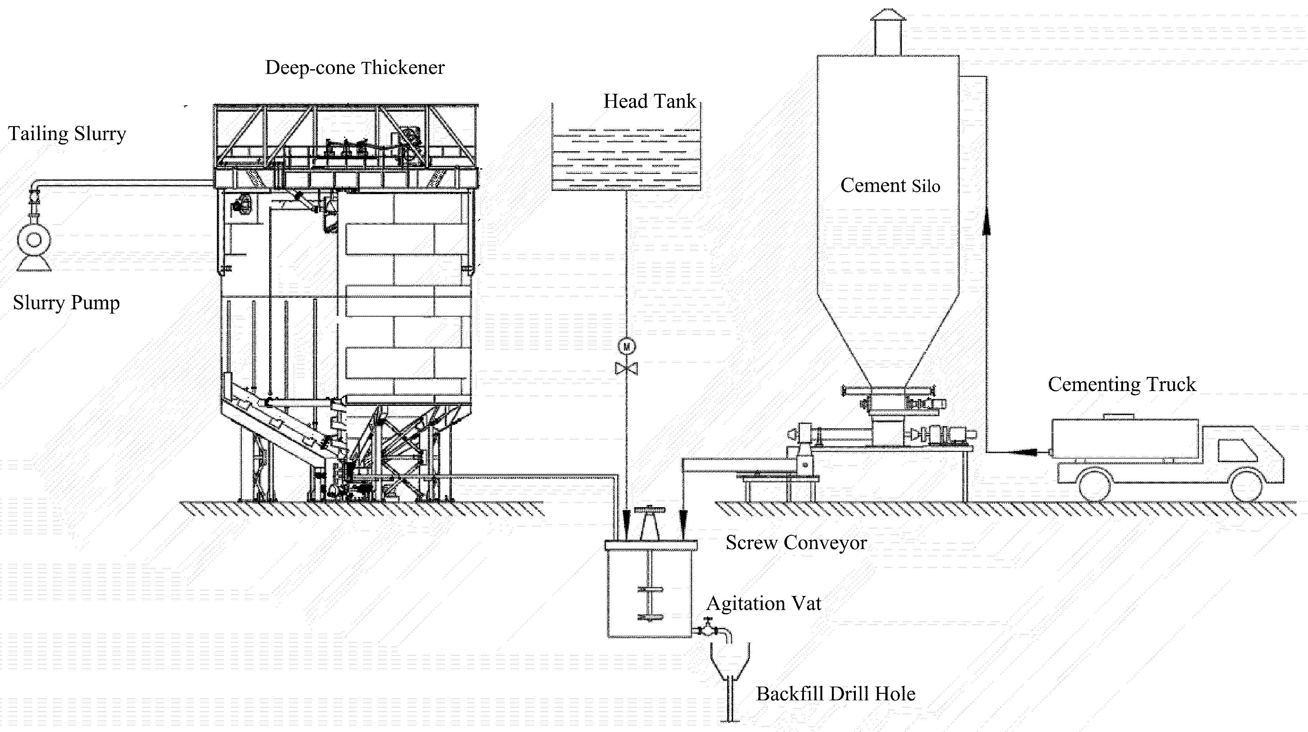
2.3.2. Process Flow of Deep-Cone Thickener Backfill System Process

In comparison with the vertical sand silo, the deep cone thickener has a larger processing capacity, higher efficiency, higher underflow concentration, and more stability. Accordingly, since 2010, the newly built full tailings backfill system of large and medium-sized mines in China mainly uses the deep cone thickener as the core tailings concentration and storage equipment. The deep cone thickener also needs to be equipped with a special flocculent preparation and addition system to speed up the sedimentation rate of fine particles in the total tailings to achieve the highest feasible bottom flow concentration and clear overflow. As shown in Figure 4, the slurry body with a mass concentration of about 20% produced in the concentrator is pumped to the deep-cone thickener in the backfill station by the slurry pump. Under the action of the flocculent, the sedimentation rate of fine particle size of the whole tailings is greatly accelerated, and the high concentration of bottom flow and clear overflow water with a bottom flow concentration of 60–70% can be obtained.
The high concentration bottom flow of the deep-cone thickener is fully stirred with water and cementitious materials in a mixing bucket according to a certain backfill ratio to prepare qualified backfill slurry, which is then transported to the area to be filled in each middle section by a backfill drill hole and underground pipeline [20,21].

3. Application Examples of Backfill Systems in China

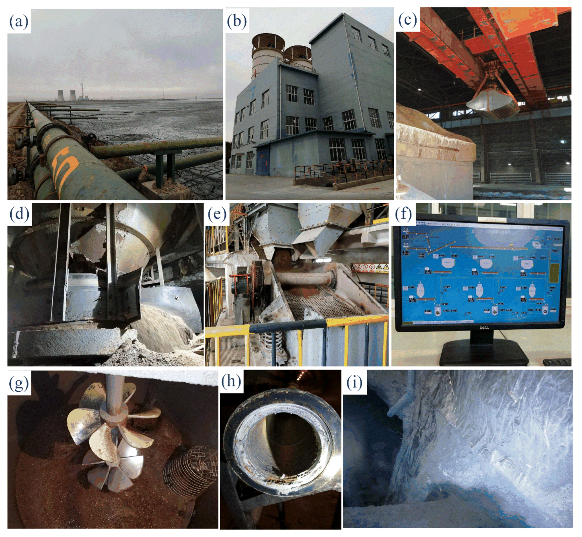
3.1. Rod Grinding Paste Backfill System of Gansu Jinchuan Group Co., LTD, Jinchang, China

3.1.1. Mine Profile and Backfill System Equipment

The Jinchuan Nickel deposit is well known for its polymetallic symbiotic large copper nickel sulfide deposits, which are concentrated in the area of 6.5 km in length and 500 m in width under Longshou Mountain. The proven ore reserves are 520 million tons, the nickel metal reserves are 5.5 million tons, ranking third in the world, and the copper metal reserves are 3.43 million tons, ranking second in China. As a rare high grade and high value ore deposit at home and abroad, the mining technical conditions of the ore body in Jinchuan mine area are extremely complex and it is difficult to mine this ore body. At present, Jinchuan Company has become the leading super large modern green mine in China. Its unique downward hexagonal approach backfill method is equipped with mechanized mining equipment such as the drill trolley, scraper, and patio drill, with a production capacity of up to 4.5 million t/a [22].
Due to the large production capacity of Jinchuan Company, several mining areas under Jinchuan Company have built independent backfill systems, with a single system backfill capacity of 100–120 m3/h and an annual backfill total of 1.7 million m3. About 90% of the backfill slurry can be transported by gravity, and a small number of areas need pressure pumping backfill. The Jinchuan rod grinding backfill system is mainly composed of: backfill aggregate preparation, the feeding system, mixing system, and pipeline conveying system. The elements of the system are presented in Figure 5.

3.1.2. Backfill Ratio Parameters

Due to the restriction of the beneficiation process and the influence of market conditions, there are still many valuable elements in the total tailings produced by Jinchuan Company’s, beneficiation which cannot be recovered. Therefore, they decided to build a reservoir to discharge and store the tailings, and then comprehensively recover and utilize the tailings after the breakthrough of the beneficiation process. Considering that Jinchuan company’s annual backfill volume is as high as 1.7 million m3, it is in urgent need of backfill aggregate with a wide range of sources, low price, and nontoxic to meet the demand of underground backfill mining. Jinchang city, where Jinchuan company is located, is located in the middle of the Hexi Corridor of Gansu Province in northwest China, and the vast Alxa Desert is in the north. Due to the arid climate and barren land in the mining area, the Gobi aggregate on the surface is more than rich. Therefore, the Gobi aggregate around the mining area is collected, which is ground by the rod mill and processed into −3 mm fine sand as backfill aggregate (called rod grinding).
As China attaches great importance to waste recycling, the backfill aggregate of the mine has changed from the traditional Gobi sand to mining mountain sand, and the whole tailings waste gypsum body backfill system is being prepared. By crushing Gobi aggregate to less than 3 mm, controlling the ratio of cement to sand as 1:4, and the mass concentration of backfill slurry as 77–79%, the compressive strength of the artificial false roof backfill after laying steel mesh can reach 4–5 MPa in 28 d [23,24].

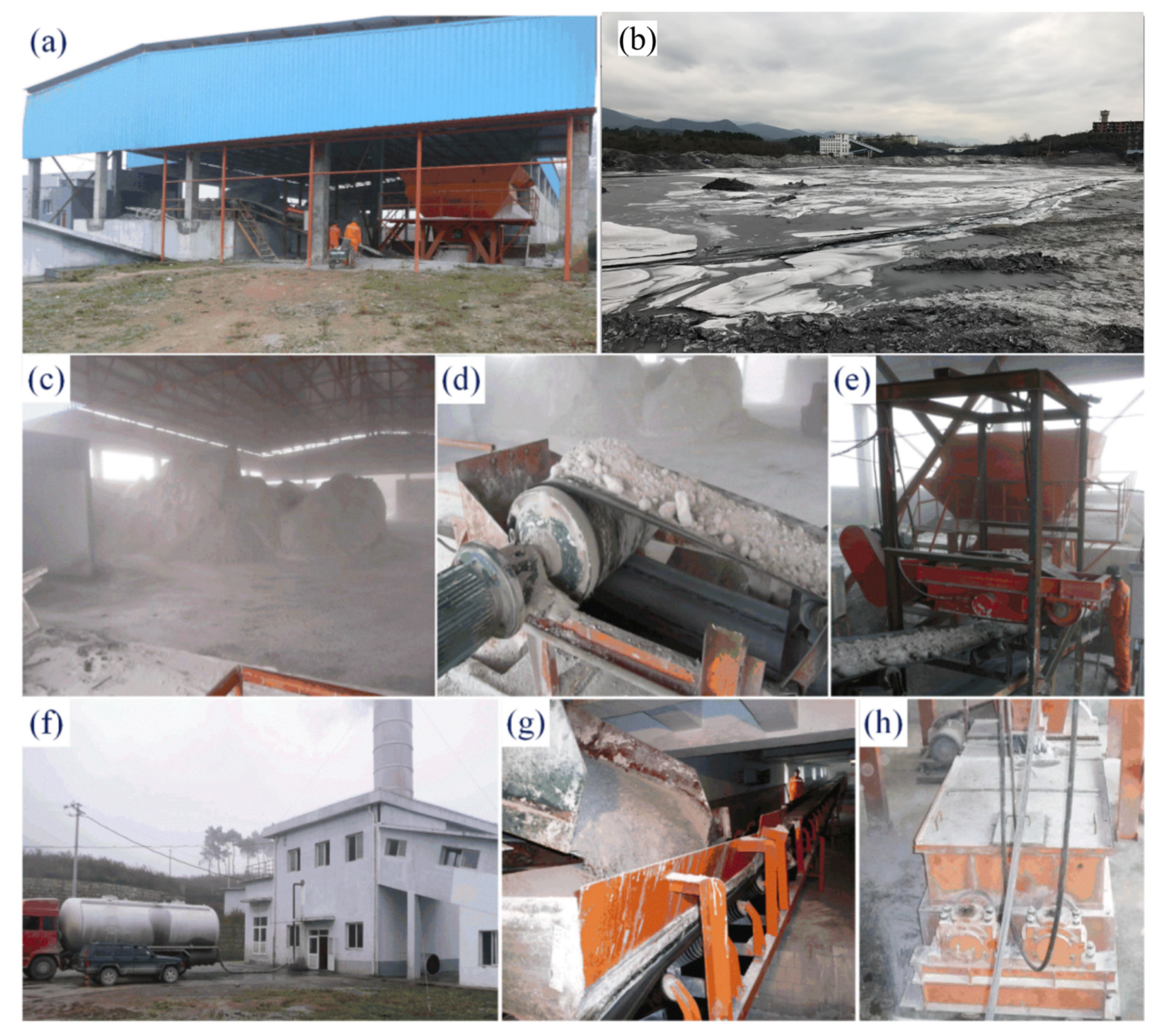
3.2. Phosphogypsum Paste Backfill System of Guizhou Kai-Lin Group Co., LTD, Guiyang, China. (Kaiyang Phosphorus Mine)

3.2.1. Mine Profile and Backfill System Equipment

The Kai-lin Mine (Kaiyang Phosphorus Mine) is located in Jinzhong Town, Kaiyang County, Guiyang city, a mining area of 50 km2, with proved phosphate resource reserves of 413 million tons, an average content of P2O5 33.73%, concentrated in 78% of the country’s high-quality phosphate ore. It is one of the world’s few, the only high-quality raw material without mineral processing, which can directly produce a high concentration of phosphate fertilizer. It is also an ideal wet fertilizer raw material and high quality raw material for producing pollution-free green phosphorus chemical products. The production capacity of phosphorus mining is 5 million t/a. The production technology and equipment have reached a first-class level in China and an advanced level in the world. It has developed into the largest underground chemical mine in China [25,26].
The main function of the backfill preparation station is to make qualified cemented backfill slurry made of yellow phosphorus slag, phosphogypsum, or cement with water, and transport it to the stope to be filled underground through drilling and pipelines. Therefore, the preparation station has facilities to store yellow phosphorus slag, cement, ultrafine powder, phosphogypsum and water, as well as measurement and transportation equipment, mixing equipment, etc., to ensure that the feed water is fed according to the correct ratio and concentration, as well as instruments to detect the slurry concentration and the flow rate.
Phosphogypsum of the mining industry is stacked in the surface yard, scooped and loading by a loader into a stable bin, fed to a self-made vertical breaking machine through a vibrating ore drawing machine and belt conveyor, and then transferred to a double-shaft mixer through the belt conveyor, with water added and mixed after being unloaded into a strong activation mixer. It is mixed with cement and yellow phosphorus slag to make qualified backfill slurry. After removing large impurities through the sieve funnel, the backfill slurry enters the backfill borehole and pipeline and is transported to the stope to be filled by self-flow. Elements of the system are presented in the Figure 6.

3.2.2. Backfill Ratio Parameters

Kai-lin Mine has reached a production capacity of 680,000 t/a phosphoric acid and 13,000 t/a yellow phosphorus, with annual discharge of 3.4 million t of phosphogypsum and 130,000 t of yellow phosphorus slag.
Through a large number of backfill ratio tests, the ratio of subsequent backfill or ordinary backfilling in phosphorus mining is yellow phosphorus slag: phosphogypsum (mass ratio) = 1:4, the addition of lime is 5% of the content of yellow phosphorus slag, and the mass concentration is 57%.
The compressive strength of the backfill ratio for 7 d, 28 d, and 60 d is 0.25 MPa, 0.87 MPa, and 0.85 MPa, respectively. The recommended ratio for pouring surface backfill is cement: yellow phosphorus slag: phosphogypsum (mass ratio) = 1:4:5, the addition of lime is 5% of yellow phosphorus slag, and the mass concentration is 60%. The compressive strength of this ratio is 0.38 MPa, 3.22 MPa, and 3.95 MPa for 7 d, 28 d, and 60 d, respectively.

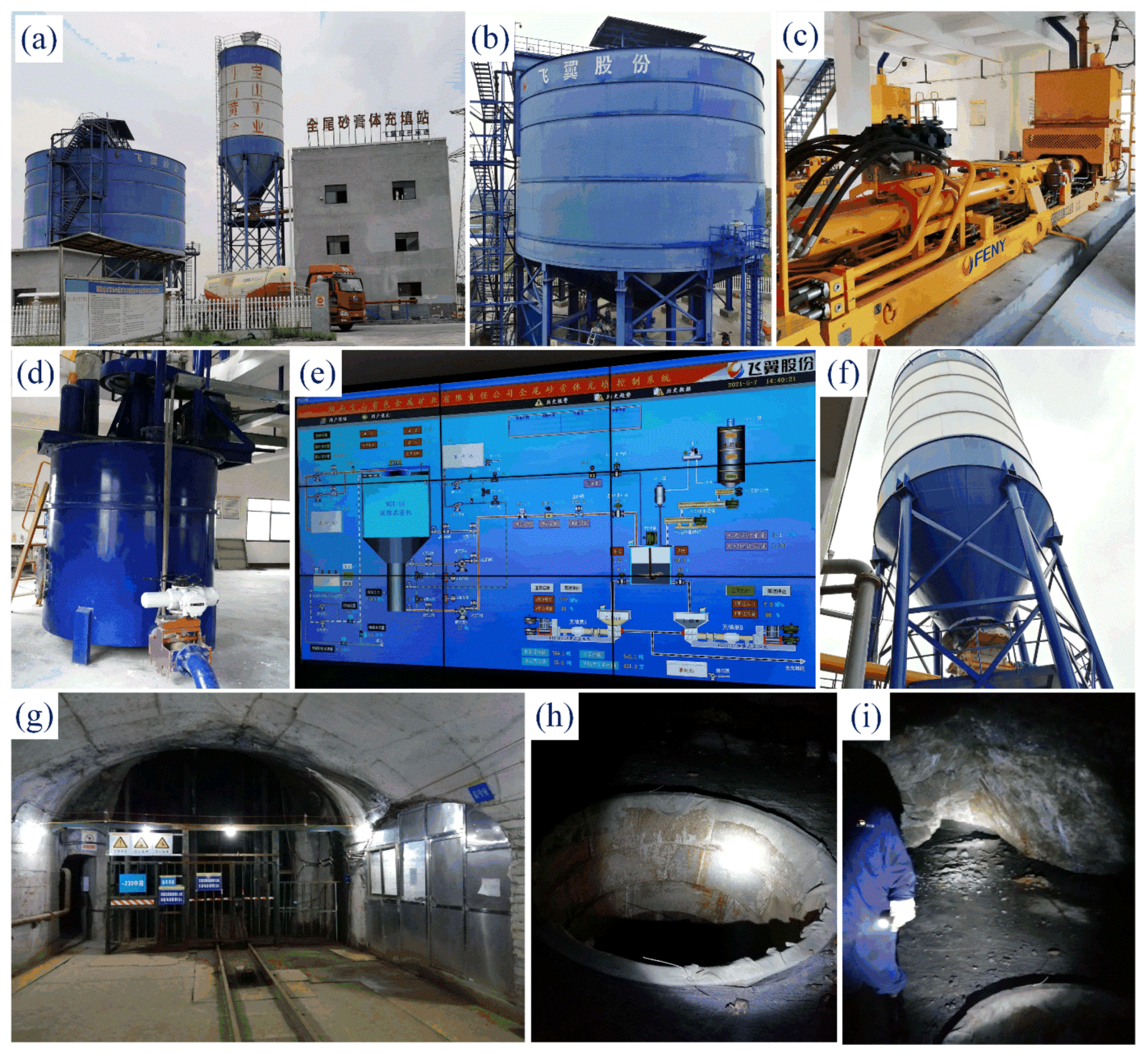
3.3. Full Tailings Paste Backfill System in Hunan Baoshan Mining Co., LTD, Chenzhou, China

3.3.1. Mine Profile and Backfill System Equipment

The Hunan Baoshan Non-ferrous Metal Mining Co., Ltd. has a mining right of 5.21 km2, with a designed production scale of 495,000 t/a. It has rich resource reserves, high ore grade and considerable prospective resource reserves in the deep side [27].
Elements of the system are presented in Figure 7. An Ngt-16 deep cone thickener produced by Feiyi Co., LTD, Changsha, China was selected for the deep cone thickener. The diameter of the deep cone thickener is 16 m, the height of the side wall is 10 m (the upper part is 2 m for water overflow layer), the cone angle of the pool bottom is 30°, and the total volume of mud layer is 1918 m3.
The pipe connecting the bottom of the feeding port of the deep cone thickener and the mixing barrel is a seamless steel pipe of φ168 mm × 12 mm with an inner diameter of 144 mm and a steel pipe wall thickness of 12 mm.
They purchased a 300 t finished cement warehouse, and the bottom of the warehouse is connected with a set of biaxial weighing spiral feeders, a set of primary spiral feeders, and a set of secondary spiral weighingfeed to the mixing drum.
In addition, an single machine dust-collector was installed on the top of the cement bin, and gasification plates were installed around the bottom of the bin.

3.3.2. Backfill Ratio Parameters

The density of the whole tailings in Baoshan Mine is 2.83 g/cm3, and the proportion of particles below −0.075 mm is 69.1%. The median particle size is only 0.049 mm, and the average particle size is 0.076 mm. The mining methods in Baoshan Mine are the upward horizontal slicing and backfill mining method and the upward drift backfill method in mechanized panel. The backfill ratio test results are shown in Table 1. The optimal anionic A110 flocculent was determined by laboratory dynamic flocculation and sedimentation test. The dosage was 50 g/t, the dilution concentration of pulp was about 11%, and the feeding rate was 0.51 t/m2·h.

3.3.3. Backfill System Process

The design capacity of the backfill system is 80 m3/h, and the specific process flow is as follows: the full-tail mortar with a mass concentration of about 20% discharged from the concentrator is pumped to the deep cone thickener with a diameter of 16 m in the backfill preparation station through the slurry pump. When sand is supplied to the deep cone thickener, flocculent is added through the flocculent adding system to improve the sedimentation rate of the total tailings and reduce the solid content of the overflow water. Full settlement of backfilling enrichment backs out of the overflow of the artesian water to the deep cone thickener set of grit chamber, after settling the pit precipitation of fine mud overflow to the clear water reservoirs, used as a backfill production water, part of the excess from the mill plant by pipe to the tailings backfilling emissions, by tailings sewage treatment station after processing used for mineral water and waste water recycling. The cementing material (cement) required for backfill is transported to the backfill preparation station by the cement tanker, and pneumatically conveyed to the cement bin for storage. During backfill, the high-concentration slurry obtained by the deep cone thickener after dynamic settlement is released from the sand outlet at the bottom of the cone after metering control and conveyed to the mixing barrel by pipeline. Cementing materials move through the bottom of the cement warehouse screw conveyor (including the spiral feeder and the spiral electronic scale), according to the ratio of backfill strength requirements, into to the mixing drum metering feed. The backfill material is fully stirred in the mixing barrel to prepare the qualified paste of backfill slurry, which is pumped to the area to be filled in each middle section of the shaft through the 330 main adit and inclined shaft backfill pipe through the backfill industrial pump [28,29].

4. Discussion and Conclusions

With the gradual reduction in mine resources and the continuous improvement of ecological environment protection requirements, more and more attention will be paid to the improvement of ore recovery rate in the mining process. The popularization and application of the backfill mining method can effectively solve a series of technical problems caused by the continuous expansion of the mining scale and the mining depth of underground metal mines. With the development of backfill technology in China, the construction of the backfill system is gradually maturing in China.
In recent years, the rapid development of science and technology in China has promoted the development of the backfill mining method [30,31], the backfill mining method in China has gone through three stages: 1. The first stage (1960 to 1980): Water and sand backfill; 2. The second stage (1980 to 2000): Graded tailings backfill; 3. The third stage (2000 to present): Full tailings backfill.
Since the second stage, China’s backfill system has gradually emerged, especially since 2010. In 2013, to improve ground stability and reduce ore dilution, L. Li [32] redesigned the drainage function of the conventional backfilling system in the stope, and Yang K. et al. [33] completed the same research in 2018. In 2014, on the basis of reviewing the current clean coal mining technology, Chang Q. et al. [34] introduced the technical principle and process flow of coal paste backfill mining, discussed the composition and characteristics of backfill materials, and the composition of backfill system and backfill technology; at the same time, the concrete implementation of the technique and its application in China of a certain mine of paste backfill mining were analyzed, and the application practice showed that the paste backfilling mining rate could improve the safety of coal mining and excavation, such as by using coal gangue solid waste resources, effectively solved the problem of surface subsidence caused by underground mining activities. In 2015, Wu A. et al. [35] identified the cement backfill’s coagulation delay and poor strength performance as the two major challenges facing China’s backfill systems. They conducted many studies and experiments on this issue and presented their views on the development of China’s backfill systems; and recently, Zhang X. et al. [36] began to study the construction of deep mining backfill system and put forward the concept of phase change heat storage backfill.
With the development of science and technology [37,38], the filling system will undoubtedly mature further.
This paper was divided into two parts to introduce the research progress of the backfill system in China in recent years. In the first section, this paper introduced the composition the different backfill systems, namely, the grading tailings backfill system, the full tailings backfill system, and the high water fast setting material backfill system.
In the second section, this paper introduced the application of the backfill system of typical mines in China and conducted a case analysis and discussion. The general situation of each major mine, backfill ratio parameters, backfill system composition, the backfill process and main backfill equipment were introduced in this section.
As a guide for readers to understand the development of China’s mining industry, Part II systematically reviewed the backfill materials and backfill systems, and summarized and evaluated the application of backfill systems in various mines, which play a role in the future development of backfill mining. At the same time, we also call on relevant researchers to actively invest in the research of backfill mining, and promote the rapid development of the backfill mining method, which will undoubtedly bring good results beyond China.
Finally, we claim that the case report serves just as a guide to starting a conversation, and we hope many more experts and scholars will be interested and engage in the research of this field.

Author Contributions

Conceptualization, S.L.; validation, H.Y.; investigation, H.Y.; resources, S.L.; writing—original draft preparation, S.L.; writing—review and editing, H.Y., S.L. and Z.Z.; visualization, H.Y.; supervision, H.Y.; project administration, X.W.; funding acquisition, S.L. All authors have read and agreed to the published version of the manuscript.

Funding

This research was funded by the National Natural Science Foundation of China (Grant No. 51804337) and the Natural Science Foundation of Hunan Province (Grant No. 2021JJ40745).

Data Availability Statement

Not applicable.

Acknowledgments

First of all, the authors thank the Natural Science Foundation of China (Grant No. 51804337) and the Natural Science Foundation of Hunan Province (Grant No. 2021JJ40745) for their financial support; secondly, the authors express their gratitude to the Chinese experts in the research field of backfill mining method for their efforts in the development of China’s mining industry; finally, the authors express sincere thanks to Central South University.

Conflicts of Interest

The authors declare no conflict of interest.

References

  1. Grice, T. Underground mining with backfill. In 2nd Annual Summit Œ Mine Tailings Disposal Systems, Nov; Academia Publisher: Brisbane, Australia, 1998; pp. 24–25. [Google Scholar]
  2. Yao, Y.; Cui, Z.; Wu, R. Development and challenges on mining backfill technology. J. Mater. Sci. Res. 2012, 1, 73. [Google Scholar] [CrossRef]
  3. Zhang, J.; Li, M.; Taheri, A.; Zhang, W.; Wu, Z.; Song, W. Properties and application of backfill materials in coal mines in China. Minerals 2019, 9, 53. [Google Scholar] [CrossRef] [Green Version]
  4. Zhang, J.; Zhang, Q.; Sun, Q.; Gao, R.; Germain, D.; Abro, S. Surface subsidence control theory and application to backfill coal mining technology. Environ. Earth Sci. 2015, 74, 1439–1448. [Google Scholar] [CrossRef]
  5. Zhang, J.; Deng, H.; Taheri, A.; Deng, J.; Ke, B. Effects of superplasticizer on the hydration, consistency, and strength development of cemented paste backfill. Minerals 2018, 8, 381. [Google Scholar] [CrossRef] [Green Version]
  6. Yin, S.; Shao, Y.; Wu, A.; Wang, H.; Liu, X.; Wang, Y. A systematic review of paste technology in metal mines for cleaner production in China. J. Clean. Prod. 2020, 247, 119590. [Google Scholar] [CrossRef]
  7. Ju, F.; Zhang, J.; Zhang, Q. Vertical transportation system of solid material for backfilling coal mining technology. Int. J. Min. Sci. Technol. 2012, 22, 41–45. [Google Scholar] [CrossRef]
  8. Deng, D.Q.; Liu, L.; Yao, Z.L.; Song, K.I.; Lao, D.Z. A practice of ultra-fine tailings disposal as filling material in a gold mine. J. Environ. Manag. 2017, 196, 100–109. [Google Scholar] [CrossRef]
  9. Qin-li, Z.; Hu, G.-Y.; Wang, X.-M. Hydraulic calculation of gravity transportation pipeline system for backfill slurry. J. Cent. South Univ. Technol. 2008, 15, 645–649. [Google Scholar]
  10. Yu, H.; Li, S.; Wang, X. The Recent Progress China Has Made in the Backfill Mining Method, Part I: The Theory and Equipment of Backfill Pipeline Transportation. Minerals 2021, 11, 1274. [Google Scholar] [CrossRef]
  11. Yaping, W. Some Experience Gained in Design of, Long-distance Pipeline Water Delivery System. Hydraul. Coal Min. Pipeline Transp. 2003, 3, 9–12. [Google Scholar]
  12. Hao-yuan, G.O.N.G. A New Technique for the Treatment of Negative Pressure Section of Backfilling Pipeline System. Min. Res. Dev. 2000, 6, 6. [Google Scholar]
  13. Chen, X.; Shi, X.; Zhou, J.; Du, X.; Chen, Q.; Qiu, X. Effect of overflow tailings properties on cemented paste backfill. J. Environ. Manag. 2019, 235, 133–144. [Google Scholar] [CrossRef]
  14. Qi, C.; Fourie, A. Cemented paste backfill for mineral tailings management: Review and future perspectives. Miner. Eng. 2019, 144, 106025. [Google Scholar] [CrossRef]
  15. Cheng, H.Y.; Wu, S.C.; Zhang, X.Q.; Wu, A.X. Effect of particle gradation characteristics on yield stress of cemented paste backfill. Int. J. Miner. Metall. Mater. 2020, 27, 10–17. [Google Scholar] [CrossRef]
  16. Li, J.; Yilmaz, E.; Cao, S. Influence of Solid Content, Cement/Tailings Ratio, and Curing Time on Rheology and Strength of Cemented Tailings Backfill. Minerals 2020, 10, 922. [Google Scholar] [CrossRef]
  17. Chen, Q.; Zhang, Q.; Wang, X.; Xiao, C.; Hu, Q. A hydraulic gradient model of paste-like crude tailings backfill slurry transported by a pipeline system. Environ. Earth Sci. 2016, 75, 1–9. [Google Scholar] [CrossRef]
  18. Xue, G.; Yilmaz, E.; Song, W.; Yilmaz, E. Influence of fiber reinforcement on mechanical behavior and microstructural properties of cemented tailings backfill. Constr. Build. Mater. 2019, 213, 275–285. [Google Scholar] [CrossRef]
  19. Xu, W.; Cao, P.; Tian, M. Strength development and microstructure evolution of cemented tailings backfill containing different binder types and contents. Minerals 2018, 8, 167. [Google Scholar] [CrossRef] [Green Version]
  20. Jiao, H.; Wu, A.; Wang, H.; Zhong, S.; Ruan, R.; Yin, S. The solids concentration distribution in the deep cone thickener: A pilot scale test. Korean J. Chem. Eng. 2013, 30, 262–268. [Google Scholar] [CrossRef]
  21. Cheng, H.; Liu, J.; Wu, S.; Zhang, X. Fluidization Analysis of Thickening in the Deep Cone for Cemented Paste Backfill. Adv. Mater. Sci. Eng. 2020, 6, 2020. [Google Scholar] [CrossRef]
  22. Ding, K.; Ma, F.; Guo, J.; Zhao, H.; Lu, R.; Liu, F. Investigation of the mechanism of roof caving in the Jinchuan nickel mine, China. Rock Mech. Rock Eng. 2018, 51, 1215–1226. [Google Scholar] [CrossRef]
  23. Ma, F.; Zhao, H.; Yuan, R.; Guo, J. Ground movement resulting from underground backfill mining in a nickel mine (Gansu Province, China). Nat. Hazards 2015, 77, 1475–1490. [Google Scholar] [CrossRef]
  24. Ma, F.S.; Deng, Q.H.; Cunningham, D.; Yuan, R.M.; Zhao, H.J. Vertical shaft collapse at the Jinchuan Nickel Mine, Gansu Province, China: Analysis of contributing factors and causal mechanisms. Environ. Earth Sci. 2013, 69, 21–28. [Google Scholar] [CrossRef]
  25. Chen, J.S.; Zhao, B.; Wang, X.M.; Zhang, Q.L.; Wang, L. Cemented backfilling performance of yellow phosphorus slag. Int. J. Miner. Metall. Mater. 2010, 17, 121–126. [Google Scholar] [CrossRef]
  26. Wang, X.M.; Zhao, B.; Zhang, Q.L. Cemented backfill technology based on phosphorous gypsum. J. Cent. South Univ. Technol. 2009, 16, 285–291. [Google Scholar] [CrossRef]
  27. Meifang, Y. Study and Application of Mobile Backfilling System in the Underground Metal Mine. Met. Mine 2011, 9, 9. [Google Scholar]
  28. Yin-Pei, Y.A.O. Study on Pumping and Cementing Backfill Technology of Underground Fractured Rocks in High Water Mine. Met. Mine 2013, 42, 59. [Google Scholar]
  29. Mei-Fang, Y.U.A.N. Application of Rock-clay Cementing Backfill System in Baoshan Mine and its Cost Analysis. Met. Mine 2013, 42, 46. [Google Scholar]
  30. Yu, H.; Li, S. The Function Design for the Communication-Based Train Control (CBTC) System: How to Solve the Problems in the Underground Mine Rail Transportation? Appl. Syst. Innov. 2021, 4, 31. [Google Scholar] [CrossRef]
  31. Nardo, M.D.; Yu, H. Intelligent Ventilation Systems in Mining Engineering: Is ZigBee WSN Technology the Best Choice? Appl. Syst. Innov. 2021, 4, 42. [Google Scholar] [CrossRef]
  32. Li, L. A new concept of backfill design-Application of wick drains in backfilled stopes. Int. J. Min. Sci. Technol. 2013, 23, 763–770. [Google Scholar] [CrossRef]
  33. Yang, K.; Thuo, J.N.; Huynh, V.D.A.; Nguyen, T.S.; Portelinha, F.H.M. Numerical evaluation of reinforced slopes with various backfill-reinforcement-drainage systems subject to rainfall infiltration. Comput. Geotech. 2018, 96, 25–39. [Google Scholar] [CrossRef]
  34. Chang, Q.; Chen, J.; Zhou, H.; Bai, J. Implementation of Paste Backfill Mining Technology in Chinese Coal Mines. Sci. World J. 2014, 2014, 821025–821028. [Google Scholar] [CrossRef]
  35. Wu, A.; Wang, Y.; Wang, H.; Yin, S.; Miao, X. Coupled effects of cement type and water quality on the properties of cemented paste backfill. Int. J. Miner. Process. 2015, 143, 65–71. [Google Scholar] [CrossRef]
  36. Zhang, X.; Xu, M.; Liu, L.; Liu, L.; Wang, M.; Ji, H.; Song, K.I. The Concept, Technical System and Heat Transfer Analysis on Phase-Change Heat Storage Backfill for Exploitation of Geothermal Energy. Energies 2020, 13, 4755. [Google Scholar] [CrossRef]
  37. Li, S.; Zhang, Y.; Feng, R.; Yu, H.; Pan, J.; Bian, J. Environmental Safety Analysis of Red Mud-Based Cemented Backfill on Groundwater. Int. J. Environ. Res. Public Health 2021, 18, 8094. [Google Scholar] [CrossRef]
  38. Li, S.; Zhang, R.; Feng, R.; Hu, B.; Wang, G.; Yu, H. Feasibility of Recycling Bayer Process Red Mud for the Safety Backfill Mining of Layered Soft Bauxite under Coal Seams. Minerals 2021, 11, 722. [Google Scholar] [CrossRef]
Figure 1. (Source elaborated by authors) Process flow of coarse particle size grading tailings backfill system.
Minerals 11 01362 g001
Figure 2. (Source elaborated by authors) Process flow of fine particle size grading tailings backfill system.
Minerals 11 01362 g002
Figure 3. (Source elaborated by authors) Process flow of vertical sand silo backfill system.
Minerals 11 01362 g003
Figure 4. (Source elaborated by authors) Process flow of deep-cone thickener backfill system process.
Minerals 11 01362 g004
Figure 5. (Source: Gansu Jinchuan Group Co., LTD, Jinchang, China) Rod grinding paste backfill system configuration diagram of Jinchuan group company: (a) tailings pond; (b) outdoor view of backfill station; (c) Gobi aggregate yard; (d) disk feeder feeding; (e) shaker; (f) control systems; (g) double spiral blades inside the stirring drum; (h) ceramic lined tubes; and (i) the backfill body in the approach.
Minerals 11 01362 g005
Figure 6. (Source: Kai-lin Group Co., LTD, Guiyang, China) Configuration diagram of the Kai-lin Mine Backfill system in the mining industry: (a) panorama of backfill station; (b) phosphogypsum storage yard (outside); (c) phosphogypsum storage yard (inside); (d) phosphogypsum conveyor; (e) stable hopper; (f) cement silos; (g) belt conveyors; and (h) horizontal double-shaft mixer.
Minerals 11 01362 g006
Figure 7. (Source: Hunan Baoshan Mining Co., LTD, Chenzhou, China) Configuration diagram of paste backfill system of Hunan Baoshan Mining Co., LTD: (a) panorama of backfill station; (b) deep cone thickener; (c) backfill industrial pump; (d) vertical stirring drum; (e) control systems; (f) cement silos; (g) man-material shaft; (h) stope chute; and (i) backfill body exposed in stope.
Minerals 11 01362 g007
Table 1. Design of full tailings backfill ratio and performance parameters in Baoshan Mine.
Use of BackfillCement-Sand RatioMass Concentration (%)28 d Intensity (MPa)Avoirdupois (t/m3)Bleeding Rate (%)Fall Degree (cm)
Rubber surface backfill1:672–742.2–2.361.84–1.932.06–1.9924.0–18.5
One step artificial pillar1:1072–741.02–1.201.81–1.902.55–2.4726.7–20.1
Two step (or subsequent)1:2072–740.30–0.341.70–1.723.51–3.0327.5–20.5
Publisher’s Note: MDPI stays neutral with regard to jurisdictional claims in published maps and institutional affiliations.

