Article

Effective Removal of Barrier Layer on the Surface of Low-Nickel Matte in an FeCl3-HCl-H2O Solution

State Key Laboratory of Advanced Special Steel & Shanghai Key Laboratory of Advanced Ferrometallurgy & School of Materials Science and Engineering, Shanghai University, Shanghai 200444, China
*
Author to whom correspondence should be addressed.
Minerals 2021, 11(11), 1219; https://doi.org/10.3390/min11111219
Submission received: 1 October 2021 / Revised: 25 October 2021 / Accepted: 27 October 2021 / Published: 1 November 2021
(This article belongs to the Section Mineral Processing and Extractive Metallurgy)

Abstract

:
Using ferric chloride as an oxidant, here, we investigated the leaching effect of low-nickel matte in a flow field produced by mechanical agitation. The factors affecting a leaching reaction, such as stirring speed, leaching time, low-nickel matte particle size, and inert abrasive quartz sand, were studied. X-ray diffraction (XRD), X-ray fluorescence spectroscopy (XRF), a laser particle size analyzer, optical microscopy (OM), a scanning electron microscopy (SEM) with an energy dispersive X-ray detector (EDS), and a Raman spectrometer were used to characterize the materials before and after the leaching reaction. The contents of the main metal ions such as Ni, Cu, and Co in the leaching solution were analyzed by inductively coupled plasma atomic emission spectroscopy (ICP-AES). Using the control variable method, the optimal experimental conditions were as follows: 2 mol/L FeCl3—0.5 mol/L HCl-H2O system with low-nickel matte and quartz sand (mass ratio is 1:5) and leaching at 90 °C for 8 h. The results showed that the blocking effect of the solid product sulfur layer was effectively removed and continuous leaching was realized. The leaching efficiencies of Ni, Cu, and Co were 98.9%, 99.3%, and 98.1%, respectively.

1. Introduction

Nickel is an important strategic base material which has been widely used in the fields of superalloys, stainless steel, electroplating, batteries, catalytic materials, and magnetic materials due to its excellent properties [1]. Currently, industrial-scale nickel production is mainly based on the raw material of sulfide ore and has adopted the process route of combining pyrometallurgy and hydrometallurgy [2,3,4]. As an intermediate product of the pyrometallurgical nickel metallurgy process, low-nickel matte is a mixed sulfide system containing nickel, copper, cobalt, and iron, which is obtained by removing most gangue from nickel sulfide concentrate by flash furnace or electric furnace smelting [5]. Usually, low-nickel matte needs further oxygen-enriched blowing in a converter to remove the iron element in low-nickel matte and to obtain high nickel matte [6]. After grinding, flotation, separation, and the electrolytic refining process, finally, metal nickel is obtained [7,8,9]. However, at the same time as iron is removed during the oxygen-enriched blowing in the converter, nearly 50% of the cobalt element enters the converter slag, due to the similar chemical properties of cobalt and iron, which makes it difficult to recycle cobalt, resulting in a huge waste of resources and a reduction in the economic benefits of the nickel metallurgy process [10,11]. Currently, some studies have attempted to take low-nickel matte as the terminal product of nickel pyrometallurgy and have used it directly in the hydrometallurgical process, which can effectively reduce the loss of valuable elements such as cobalt, copper, and nickel caused by oxygen-enriched blowing and can reduce the environmental pollution caused by the emission of SO2 [12,13,14].
The hydrometallurgical process of low-nickel matte is mainly divided into pressure oxidation leaching and atmospheric oxidation leaching. Park et al. conducted an experimental discussion on the oxygen pressure acid leaching and oxygen pressure ammonia leaching of synthetic complex sulfide and found that both ammonia leaching and acid leaching could efficiently recover the relevant valuable metals, but acid leaching had a higher leaching efficiency [15,16,17]. Although oxygen pressure acid leaching can effectively recover valuable metals, its application is limited to a certain extent due to significant equipment requirements, and therefore, high investment costs. E. Muzenda et al. conducted an experimental study on oxidized ammonia leaching of nickel-copper matte under atmospheric pressure, and the leaching efficiencies of nickel and copper were less than 50% [18]. G. Chen et al. carried out FeCl3-HCl leaching experiments on low-nickel matte. The leaching efficiencies of metal elements reached Ni (98.4%), Cu (98.9%), and Co (97.3%) [19]; however, a description of the interface reaction product of the leaching process was lacking. As compared with atmospheric ammonia leaching and atmospheric acid leaching, the FeCl3-HCl-H2O leaching process has attracted more and more attention due to its simple operation and mild reaction conditions, and it is often used in sulfide leaching [20,21]. High efficiency oxidation leaching of copper, nickel, cobalt, and other target metals in metal sulfides (including CuFeS2, FeS2, (Fe,Ni)9S8, Ni3S2, etc.) can be achieved by using the oxidation property of Fe3+ in solution [22,23,24,25,26]. Atmospheric pressure oxidation leaching can transform sulfur elements in sulfide ore into elemental sulfur that enters the leaching residue. After a subsequent separation process, sulfur elements can be recycled synchronously. However, the elemental sulfur exists in a solid form in an atmospheric acid solution, which may form a barrier layer on the surface of unreacted low-nickel matte, resulting in a decrease in metal leaching efficiency and incomplete leaching of valuable metal elements. An experimental study on the mineral interface reaction, the composition, and the microstructure of the interface products during oxidation leaching of low-nickel matte at atmospheric pressure is significant for understanding the dissolution process and influencing factors of low-nickel matte, and for developing the technology to enhance leaching efficiency.
The main components of low-nickel matte include pentlandite (Fe5Ni4S8), bornite (Cu5FeS4), magnetite (Fe3O4), and Ni3Fe alloy. Among them, Fe3O4 and Ni3Fe can easily be dissolved and leached into an acidic medium; the dissolution behaviors of pentlandite and bornite are the main factors affecting the leaching efficiency of low-nickel matte. In this study, we investigated the interfacial reaction products that formed a barrier layer during leaching on the surface of low-nickel matte in an FeCl3-HCl-H2O system. At the same time, the effective removal of the barrier layer on the surface of low-nickel matte with inert abrasive was also studied. The effects of leaching time, particle size of reactants, and the relative movement of the flow field on the composition and microstructure of the interfacial reaction products of low-nickel matte in an FeCl3-HCl-H2O system were carried out by means of optical microscopy (OM), a laser particle size analyzer, scanning electron microscopy (SEM) equipped with an energy dispersive X-ray detector (EDX), and inductively coupled plasma atomic emission spectroscopy (ICP-AES). This study will deepen the understanding of oxidation leaching products of sulfide minerals in low-nickel matte in an FeCl3-HCl-H2O system and provide an alternative path for enhancing oxidation leaching of low-nickel matte under atmospheric pressure.

2. Materials and Methods

2.1. Materials and Chemical Measurements

In this study, the low-nickel matte raw material was from Jinchuan Group Co. Ltd., China (Jinchuan, China). The chemical reagents used in the experiment were all analytical reagent (AR) grade. The low-nickel matte samples were put into a drying oven at 100 °C for 24 h. After drying, the samples were set into a ball mill in batches to grind into different particle sizes (~200 mesh, ~100 mesh, ~50 mesh, and ~10 mesh). The elemental composition of the samples was determined by X-ray fluorescence spectroscopy (XRF), and the phases of the samples were analyzed by X-ray diffraction (XRD). The low-nickel matte samples were embedded in resin and the exposed low-nickel matte surface was polished. FeCl3∙6H2O and 36~38% HCl (mass fraction) hydrochloric acid were used to prepare the 2 mol/L FeCl3—0.5 mol/L HCl-H2O system with an Fe(III) concentration of 2.0 mol/L. The leaching experiment was carried out in a 500 mL flask connected with an electric mechanical stirrer and rubber plug, and the temperature was controlled by a water bath. According to the liquid/solid ratio of 20 mL:1 g, 10 g weight low-nickel matte samples and 200 mL volume of the prepared leaching system solution were taken. When the water bath temperature reached the set value of 90 °C, the low-nickel matte samples and leaching system solution were added into the flask at the same time. The stirring speed was adjusted to 200, 350, and 500 revolutions per minute for full stirring and the timing began. After reaching the predetermined leaching time, 2 mL volume of supernatant solution in the flask was taken and diluted 100 times, and the contents of nickel, copper, and cobalt metal ions in the leaching solution were detected by ICP. In order to reduce experimental errors, the above operations were repeated three times, and then the average value of the data for three times was used to calculate the leaching efficiencies of nickel, copper, and cobalt. Solid-liquid separation was realized by vacuum pump pumping and filtration. The leaching residue was cleaned with deionized water three times, and then put into a 100 °C drying oven for 12 h. The calculation formula of the leaching efficiency was as follows in Formula (1):
η x = M W x m w x M W x   ×   100 %  
where x is a metallic element, such as Ni, Cu, or Co; M and m are the mass of adding low-nickel matte and the mass of leaching residue after drying, g, respectively; Wx and wx are the mass fraction of x in low-nickel matte and leaching residue, %, respectively. The leaching residue was embedded in the resin, and then was sanded to expose the edges and polished. Then, 50 g weight of quartz sand (the main ingredient is SiO2) (25~50 mesh) was added to the leaching system as an inert abrasive; different leaching times (1–8 h) were used for leaching the low-nickel matte with different particle sizes (~200, ~100, ~50, and ~10 mesh). The experimental setup and the assembly of the rotating cylinder and the embedded low-nickel matte samples are shown in Figure 1. The conversion between the stirring rotation speed of the motor and the relative speed of the interface of the rotating cylinder follows as Formula (2):
v = 2πn × r
where v is the relative velocity, n is the revolutions per minute, and r is the radius of the rotating cylinder. The relative movement velocity between the low-nickel matte and the leaching solution is calculated here, and other weak flows of the leaching solution caused by agitation are ignored. The calculation results are shown in Table 1.

2.2. Characterization

The low-nickel matte samples were characterized by X-ray diffraction (XRD, Bruker-AXS D8 Advance, Billerica, MA, USA) using a monochromatic Cu Kα radiation at a scan rate of 6 °/min, target voltage of 40 kV, and tube current of 40 mA; X-ray fluorescence spectroscopy (XRF-1800, Shimadzu, Kyoto, Japan); optical microscopy (OM, Leica, DM4000M, Leica Camera AG, Wizlar, Germany); a laser particle size analyzer (Mastersizer 3000, Malvern Panalytical Ltd, Malvern, UK); a scanning electron microscopy (SEM, FEI Nova Nano 450, FEI, Hillsboro, OR, USA) equipped with an energy dispersive X-ray detector (EDX, Oxford INCA EDS system, Oxford Instruments, Abingdon, UK), and inductively coupled plasma atomic emission spectroscopy (ICP-AES, Perkin-Elmer 7300 DV, PerkinElmer, Waltham, MA, USA). The Raman spectra of the surfaces were recorded using a DILOR XY multichannel spectrometer with Ar+ ion laser excitation in an Olympus microscope (Ar+ laser with 532 nm excitation line and irradiation density of 0.04 mW·cm−2, 20 s × 20 accumulations at ambient temperature) (Olympus, Shinjuku/Tokyo, Japan).

3. Results and Discussion

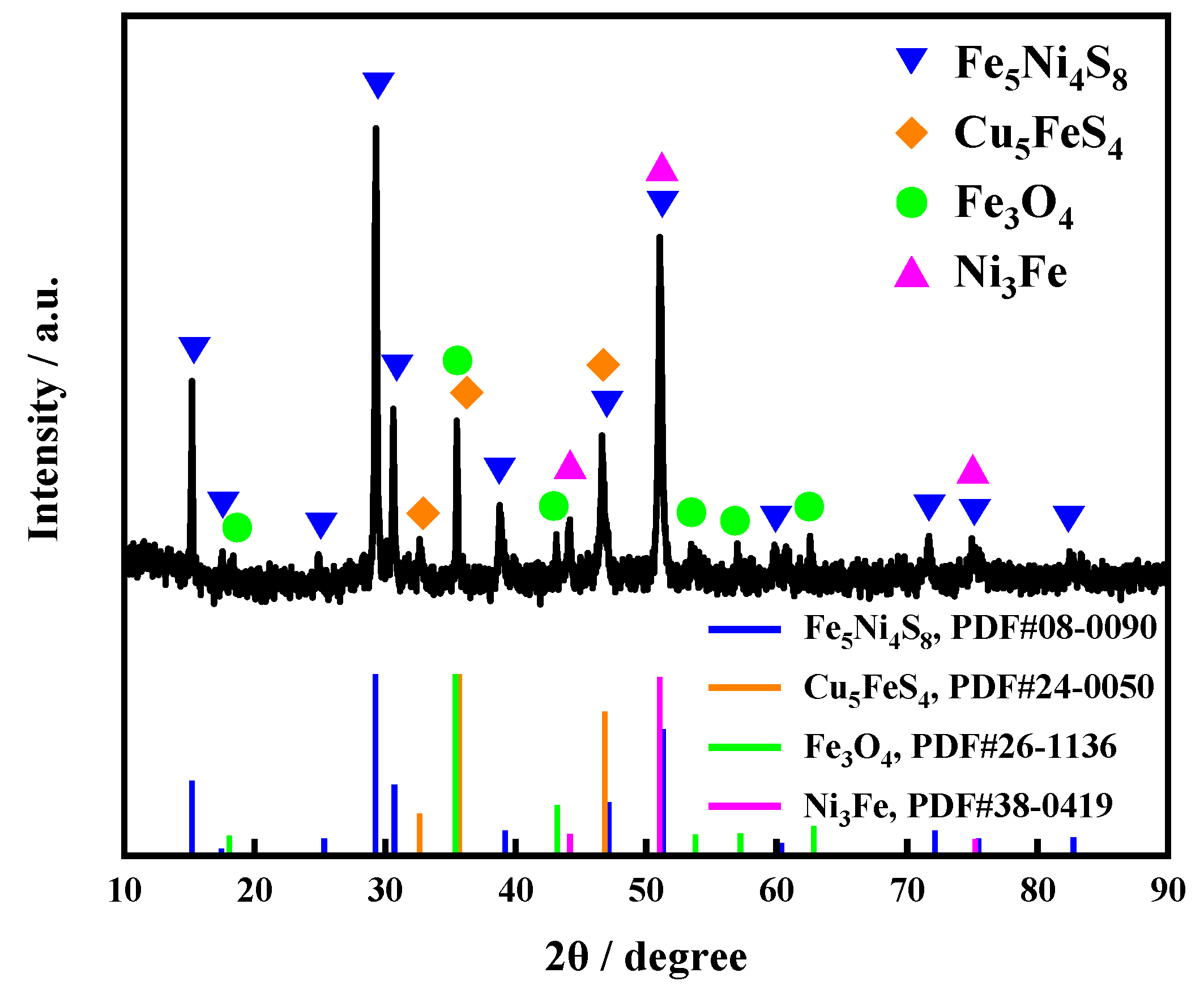
3.1. Characterization of the Low-Nickel Matte

The typical XRD pattern of the low-nickel matte is shown in Figure 2. The elemental composition of the samples was determined by XRF. The results are shown in Table 2.
It is found that the matte is composed of pentlandite (Fe5Ni4S8) and bornite (Cu5FeS4), as the two major phases, and magnetite (Fe3O4) and ferronickel (Ni3Fe) as the minor phases. The four phases can all be detected, as shown in Figure 3a, which is the OM image of the low-nickel matte with EDS analyses and Raman spectroscopies for the chosen sites. According to the iron, nickel, and sulfur atomic ratio from the EDS analysis and typical Raman spectroscopic peak (170, 458, and 531 cm−1) due to bornite [27,28,29,30], the gray island-like particles dispersed within the light-yellow matrix should be bornite. The atomic ratio of Fe, Ni, and S is about 5:4:8, and the typical peaks located at 180, 417, and 533 cm−1 are assigned to pentlandite for the chosen site (Area I) as the matrix. It can be concluded that the matrix is composed of pentlandite (Fe5Ni4S8) [30,31,32,33], which exists as a continuous phase due to its low melting point. The small particles of ferronickel (Ni3Fe) and magnetite (Fe3O4) can also be detected in the matrix according to EDS analyses, which are shown in Figure 3b. According to the chemical compositions in Table 2 and the EDS analysis from Figure 3b, the chemical compositions of the main minerals in the low-nickel matte can be calculated, as shown in Table 3.

3.2. Chemical Feasibility of the Leaching Process

According to the characterization analysis of the low-nickel matte, in order to comprehensively extract Ni, Cu, and Co from the low-nickel matte, the metal sulfide and ferronickel need to be dissolved by oxidation. Fe3+ in an acidic solution has a strong oxidizing property and is often used for oxidation leaching of metal sulfides [34]. In addition, considering the high solubility of metal chloride generated in the leaching of metal sulfide in the chloride system, and the porous and loose form of the elemental S0 generated by the reaction [35], it has little hindrance to the diffusion and mass transfer of the reactant at the initial stage of the reaction, which is conducive to the leaching of metal elements. In summary, FeCl3 was selected as an oxidant in this study, hydrochloric acid solution was added to inhibit the hydrolysis of Fe3+, and valuable metal elements in low-nickel matte were comprehensively leached in an FeCl3-HCl-H2O solution. The main reactions are shown in the following Equations (3)–(7):
Fe5Ni4S8(s) + 18FeCl3(aq) = 23FeCl2(aq) + 4NiCl2(aq) + 8S0(s)
Cu5FeS4(s) + 12FeCl3(aq) = 5CuCl2(aq) + 13FeCl2(aq) + 4S0(s)
FeNi3(s) + 8FeCl3(aq) = 9FeCl2(aq) + 3NiCl2(aq)
FeNi3(s) + 8HCl(aq) = FeCl2(aq) + 3NiCl2(aq) + 4H2(g)
Fe3O4(s) + 8HCl(aq) = FeCl2(aq) + 2FeCl3(aq) + 4H2O(aq)
According to the above equations, the target metals Ni and Cu enter the solution in the form of chloride with the dissolution of Fe5Ni4S8, Cu5FeS4, and FeNi3, and the Co associated with Fe5Ni4S8 and Fe3O4 enter the solution in the form of CoCl2 with their dissolution. Thus, high efficiency leaching of Ni, Cu, and Co can be realized.

3.3. Leaching Results of the Low-Nickel Matte Particles

Figure 4 shows the SEM and EDS images of the low-nickel matte (~10 mesh) after mechanical agitation leaching for 1, 2, and 3 h. It can be seen from Figure 4a,c,e that with an increase in leaching time, more and more interface reaction product S layers are formed on the surface of the low-nickel matte. Figure 4g is a local magnification of Figure 4c. It can be seen from Figure 4g that the main component of the product layer is porous elemental sulfur, and its pore distribution is maze-like. Few through-holes are formed between the solid sulfur product layer and the interface of unreacted low-nickel matte. Generally, solid elemental sulfur is hydrophobic, and the sulfur layer of the product will hinder the diffusion of the leaching solution to the low-nickel matte interface, making it difficult to continue the leaching reaction, resulting in the semi-passivation phenomenon of the reaction interface [36].
In order to further quantify the leaching effect of the low-nickel matte, the interfacial leaching experiments of the low-nickel matte embedded in resin at different rotational speeds were carried out. Figure 5a–i show a cross-section of the low-nickel matte sample without the addition of quartz sand at stirring speeds of 200, 350, and 500 RPM, respectively. It can be seen from Figure 5a–i that with an increase in leaching time, the product layer gradually thickens. Figure 6 is the SEM and EDS images of low-nickel matte without quartz sand leaching at 200 RPM for 3 h. In combination with Figure 5c and Figure 6a, the product layer is mainly elemental sulfur, and its macroscopic morphology does not change significantly in the leaching process. When the rotational speed is set at 350 RPM, it can be seen from Figure 5d–f that the macroscopic flatness of the product layer changes slightly. When the rotational speed is increased to 500 RPM, it can be seen from Figure 5g–i that the sulfur layer of the interface reaction product has some irregular spalling. As compared with the initial position of the interface product layer, the separation of the sulfur layer is not obvious.

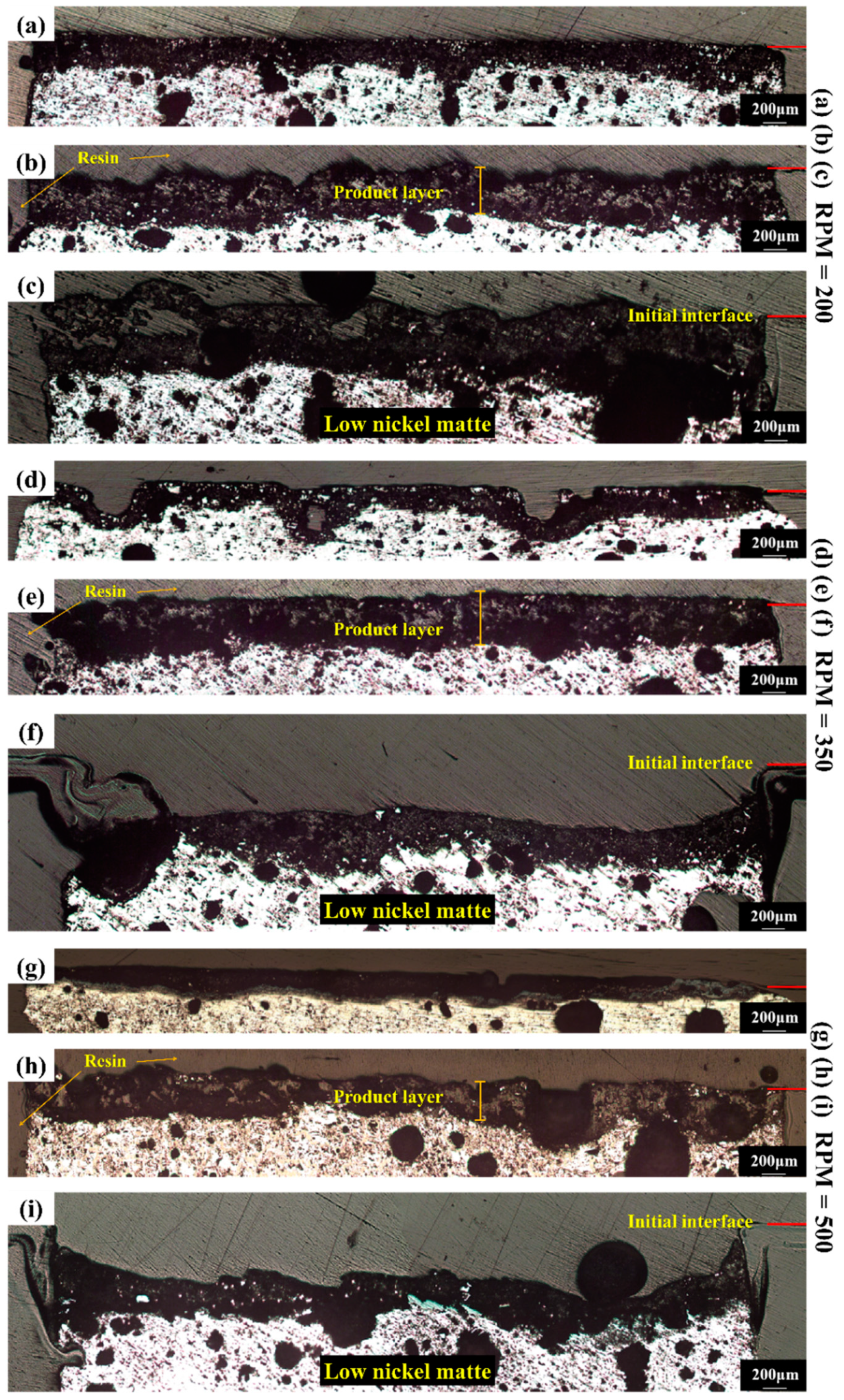
3.4. Leaching Results of the Low-Nickel Matte Interface with Quartz Sand

The leaching effect can be enhanced by reducing the coating effect of the solid product layer produced by the interface reaction. By adding an inert abrasive (quartz sand) to break the coating of the sulfur layer of the product, the fresh surface of the low-nickel matte is continuously in contact with the leaching solution; therefore, leaching can continue. Figure 7a,c are the SEM images of a section of low-nickel matte (about 10 mesh) after leaching for 1 and 2 h after adding quartz sand, respectively. Figure 7b,d are the EDS diagrams corresponding to Figure 7a,c. By comparing Figure 4 and Figure 5, it can be seen that the flow field directly generated by the agitator is difficult to peel off the generated product sulfur layer. After the addition of quartz sand, due to the interaction between quartz sand and small solid particles of low-nickel matte under the action of the agitator, the sulfur layer of the leaching product of low-nickel matte is spalling, exposing the new surface of low-nickel matte to contact with the leaching solution and continuing the interface reaction. Moreover, the longer the leaching time of adding quartz sand, the more obvious the spalling phenomenon of the product layer on the surface of the low-nickel matte. This shows that increasing the agitation leaching time of quartz sand and low-nickel matte particles is more conducive to leaching.
Figure 8a–i show a cross-section of the low-nickel matte samples with the addition of quartz sand at the stirring speeds of 200, 350, and 500 RPM, respectively. It can be seen from Figure 8a,b,d,e,g,h that with an increase in leaching time, the product layer gradually thickens. As can be seen from Figure 8a–c, elemental sulfur is the main product layer of the interface reaction, and its macroscopic morphology changes significantly in the leaching process. When the rotation speed of the motor is adjusted to 350 RPM, it can be seen from Figure 8d–f that the surface flatness of the product sulfur layer changes significantly. Particularly, as shown in Figure 8f, the continuously generated sulfur layer is continuously scoured by the quartz sand and the surface of the product layer is peeled off, which is significantly contrasted with the labeled initial reaction interface. When the stirring speed is further increased to 500 RPM, the sulfur layer produced by the interface reaction is randomly impacted by the quartz sand under the action of the high-speed flow field, making its surface more irregular. Figure 8i shows a deeper pit than Figure 8f, due to an increase in the relative velocity of the low-nickel matte surface to the quartz sand. This shows that increasing the rotational speed is more conducive to stripping sulfur coating and can further promote the leaching of low-nickel matte, thus improving the leaching effect.

3.5. Leaching Efficiency of Low-Nickel Matte with Different Particle Sizes

According to the comparison of experimental results of the three rotating speeds (200, 350, and 500 RPM), the best leaching condition is 500 r/min. Under the condition of 500 RPM, the experiments were carried out on the low-nickel matte with different particle sizes; the ICP test was carried out on the diluted leaching solution, in order to calculate the leaching efficiencies of Ni, Cu, and Co metal ions in the low-nickel matte. Figure 9a–d showed the experimental results of the leaching experiment of the low-nickel matte with particle sizes of 1700 μm (~10 mesh), 270 μm (~50 mesh), 150 μm (~100 mesh), and 75 μm (~200 mesh), respectively. As shown in Figure 9a–d, the larger the particle size of low-nickel matte, the higher the leaching efficiencies of Ni, Cu, and Co with an increase in leaching time. With a decrease in the particle size of the low-nickel matte, the final leaching efficiencies of Ni, Cu, and Co metal ions increase gradually. This is due to the same mass of low-nickel matte sample; if its particle size is larger, the number of particles is less, so its specific surface area is smaller. This will lead to a decrease in the total area of contact with the leaching solution during the leaching process, and it is easier to form the coating of the product sulfur layer; therefore, the fresh surface of the low-nickel matte cannot be exposed in time to react with the leaching solution, thus, reducing the leaching efficiencies of metal ions.

3.6. Characterization of Quartz Sand

In this experiment, a certain proportion of inert abrasive quartz sand was added during the leaching process in order to more easily break the barrier effect of the product elemental sulfur layer and strengthen the leaching of the low nickel matte. As an external additive, it is necessary to consider whether the quartz sand itself will be partially dissolved during the leaching process to introduce impurity ions. Figure 10a shows the dissolution efficiency of quartz sand in the low-nickel matte with particle sizes of 10 mesh and 50 mesh. With an increase in leaching time, the dissolution of silicon ions increases slowly until it is stable. The maximum dissolution efficiency of silicon is less than one-thousandth of the dissolution efficiency of the main leaching elements such as Ni, Cu, and Co; therefore, it shows that the influence of adding quartz sand on the introduction of low-nickel matte to leaching impurity ions is negligible. Metallographic and digital photos of quartz sand before and after leaching reaction are shown in Figure 10b. It can be seen from the digital photos that the quartz sand is slightly yellow after the leaching reaction. This is caused by constant contact with the brown-yellow solution of ferric chloride during the dynamic leaching process. According to the metallographic photos, it can be seen that, after the leaching process, the quartz sand particle morphology has not changed significantly, and its edges and corners are still very clear, indicating that the quartz sand particles have very little impact on the low-nickel matte leaching process and can be reused. Figure 10c,d shows the particle size statistics of quartz sand before and after the leaching process, respectively. According to the comparison between Figure 10c,d, it can be found that the particle size of quartz sand before and after leaching does not change slightly. In combination with Figure 10b, it is shown that quartz sand is a reliable material to promote the leaching of low-nickel matte.

4. Conclusions

The solid product of low-nickel matte oxidation leaching in an FeCl3-HCl-H2O leaching system is elemental sulfur. The solid product layer is porous and loose, and the pores are a labyrinth. The elemental sulfur covered the surface of the unreacted nickel matte, which hindered further oxidation leaching of the low-nickel matte. In the condition of stirring and adding inert abrasive quartz sand, the coating of the solid product layer can be effectively removed. The optimal conditions of the experiment were to add quartz sand to the leaching system of 2 mol/L FeCl3—0.5 mol /L HCl-H2O at 90 °C (the mass ratio of low-nickel matte (~200 mesh) to quartz sand (25~50 mesh) is 1:5), and to carry out the leaching reaction at 500 r/min for 8 h. Under these conditions, it was found that the solid product layer elemental sulfur could be stripped from the surface of the low-nickel matte, which effectively reduced the physical barrier of solid sulfur to the reaction interface of the low-nickel matte and accelerated the oxidation leaching process of the low-nickel matte. The leaching efficiencies of Ni, Cu, and Co reached 98.9%, 99.3%, and 98.1%, respectively. The inert abrasive added to the leaching system hardly dissolved in the leaching process, and the morphology was almost unchanged, therefore, it can be reused to increase economic benefit.

Author Contributions

Validation, data curation, writing—original draft, C.Z.; investigation, formal analysis, Y.L.; formal analysis, X.H.; conceptualization, writing—review and editing, Q.X.; conceptualization, supervision, X.Z.; methodology, H.C. and X.L. All authors have read and agreed to the published version of the manuscript.

Funding

This research was funded by National Natural Science Foundation of China (No. U2002214), Opening Fund of State Key Laboratory of Pressure Leaching, Kunming, China (No. yy2016009), Shanghai Rising-Star Program (19QA1403600), the Program for Professor of Special Appointment (Eastern Scholar) at Shanghai Institutions of Higher learning (TP2019041), and the National Natural Science Foundation of China (No. 52022054).

Acknowledgments

We thank the Instrumental Analysis and Research Center of Shanghai University for materials characterization.

Conflicts of Interest

The authors declare that they have no known competing financial interests or personal relationships that could have appeared to influence the work reported in this paper.

References

  1. Mu, W.; Cui, F.; Xin, H.; Zhai, Y.; Xu, Q. A novel process for simultaneously extracting Ni and Cu from mixed oxide-sulfide copper-nickel ore with highly alkaline gangue via FeCl3∙6H2O chlorination and water leaching. Hydrometallurgy 2020, 191, 105187. [Google Scholar] [CrossRef]
  2. Finkelstein, N.P. The activation of sulphide minerals for flotation: A review. Int. J. Miner. Process. 1997, 52, 81–120. [Google Scholar] [CrossRef]
  3. Cui, F.; Mu, W.; Wang, S.; Xin, H.; Xu, Q.; Zhai, Y. A sustainable and selective roasting and water-leaching process to simultaneously extract valuable metals from low-grade Ni-Cu matte. JOM 2018, 70, 1977–1984. [Google Scholar] [CrossRef]
  4. Moskalyk, R.R.; Alfantazi, A.M. Nickel laterite processing and electrowinning practice. Miner. Eng. 2002, 15, 593–605. [Google Scholar] [CrossRef]
  5. Plasket, R.P.; Romanchuk, S. Recovery of nickel and copper from high-grade matte at Impala Platinum by the Sherritt process. Hydrometallurgy 1978, 3, 135–151. [Google Scholar] [CrossRef]
  6. Lamya, R.M.; Lorenzen, L. A study of factors influencing the kinetics of copper cementation during atmospheric leaching of converter matte. J. South Afr. Inst. Min. Metall. 2005, 3, 21–28. [Google Scholar]
  7. Rademan, J.A.M.; Lorenzen, L.; van Deventer, J.S.J. The leaching characteristics of Ni-Cu matte in the acid-oxygen pressure leach process at Impala Platinum. Hydrometallurgy 1999, 52, 231–252. [Google Scholar] [CrossRef]
  8. Sui, C.C.; Brienne, S.H.R.; Rao, S.R.; Xu, Z.; Finch, J.A. Metal ion production and transfer between sulphide minerals. Miner. Eng. 1995, 8, 1523–1539. [Google Scholar] [CrossRef]
  9. Niu, Y.; Sun, F.; Xu, Y.; Cong, Z.; Wang, E. Applications of electrochemical techniques in mineral analysis. Talanta 2014, 127, 211–218. [Google Scholar] [CrossRef]
  10. Chen, G.; Gao, J.; Guo, M.Z.M. Efficient and selective recovery of Ni, Cu, and Co from low-nickel matte via a hydrometallurgical process. Int. J. Min. Met. Mater. 2017, 24, 249–256. [Google Scholar] [CrossRef]
  11. Xiao, W.; Chen, X.; Liu, X.; Zhao, Z.; Li, Y. A method for extracting valuable metals from low nickel matte by non-oxidative leaching with H2SO4. Sep. Purif. Technol. 2021, 270, 118789. [Google Scholar] [CrossRef]
  12. Xiao, W.; Liu, X.; Zhao, Z. Kinetics of nickel leaching from low-nickel matte in sulfuric acid solution under atmospheric pressure. Hydrometallurgy 2020, 194, 105353. [Google Scholar] [CrossRef]
  13. Fu, Y.; Li, B.; Fan, C.; Zhai, X.; Zhang, X.; Li, D. Selective leaching of nickel from low-sulfur Ni-Cu matte at atmospheric pressure. Trans. Nonferr. Met. Soc. 2010, 20, 71–76. [Google Scholar] [CrossRef]
  14. Huang, K.; Li, Q.; Chen, J. Recovery of copper, nickel and cobalt from acidic pressure leaching solutions of low-grade sulfide flotation concentrates. Miner. Eng. 2007, 20, 722–728. [Google Scholar] [CrossRef]
  15. Park, K.H.; Mohapatra, D.; Nam, C.W.; Kim, H.I. A comparative study of different leaching processes for the extraction of Cu, Ni and Co from a complex matte. Korean. J. Chem. Eng. 2007, 24, 835–842. [Google Scholar] [CrossRef]
  16. Park, K.H.; Mohapatra, D.; Reddy, B.R.; Nam, C.W. A study on the oxidative ammonia/ammonium sulphate leaching of a complex (Cu-Ni-Co-Fe) matte. Hydrometallurgy 2007, 86, 164–171. [Google Scholar] [CrossRef]
  17. Park, K.H.; Mohapatra, D.; Reddy, B.R. A study on the acidified ferric chloride leaching of a complex (Cu–Ni–Co–Fe) matte. Sep. Purif. Technol. 2006, 51, 332–337. [Google Scholar] [CrossRef]
  18. Muzenda, E.; Ramatsa, I.M.; Ntuli, F.; Abdulkareem, A.S.; Afolabi, A.S. Parametric effects on leaching behavior of nickel-copper matte in ammonia. Particul. Sci. Technol. 2013, 31, 319–325. [Google Scholar] [CrossRef]
  19. Chen, G.; Wang, H.; Zhang, M.; Guo, M. High efficient leaching of Ni, Cu and Co from low nickel matte. Chin. J. Nonferrous Met. 2017, 27, 1936–1942. [Google Scholar]
  20. Anand, S.; Pao, P.K.; Jena, P.K. Recovery of metal values from copper converter and smelter slags by ferric chloride leaching. Hydrometallurgy 1980, 5, 355–365. [Google Scholar] [CrossRef]
  21. Hashemzadeh, M.; Dixon, D.G.; Liu, W. Modelling the kinetics of chalcocite leaching in acidified ferric chloride media under fully controlled pH and potential. Hydrometallurgy 2019, 186, 275–283. [Google Scholar] [CrossRef]
  22. Harahsheh, M.A.; Kingman, S.; Harahsheh, A.A. Ferric chloride leaching of chalcopyrite: Synergetic effect of CuCl2. Hydrometallurgy 2008, 91, 89–97. [Google Scholar] [CrossRef]
  23. Almeida, V.O.; Schneider, I.A.H. Production of a ferric chloride coagulant by leaching an iron ore tailing. Miner. Eng. 2020, 156, 106511. [Google Scholar] [CrossRef]
  24. Carneiro, M.F.C.; Leão, V.A. The role of sodium chloride on surface properties of chalcopyrite leached with ferric sulphate. Hydrometallurgy 2007, 87, 73–82. [Google Scholar] [CrossRef] [Green Version]
  25. Maurice, D.; Hawk, J.A. Ferric chloride leaching of a mechanically activated pentlandite-chalcopyrite concentrate. Hydrometallurgy 1999, 52, 289–312. [Google Scholar] [CrossRef]
  26. Lu, Z.Y.; Jeffrey, M.I.; Zhu, Y.; Lawson, F. Studies of pentlandite leaching in mixed oxygenated acidic chloride-sulfate solutions. Hydrometallurgy 2000, 56, 63–74. [Google Scholar] [CrossRef]
  27. Adamou, A.; Nicolaides, A.; Varotsis, C. Bio-hydrometallurgy dynamics of copper sulfide-minerals probed by microFTIR mapping and Raman microspectroscopy. Miner. Eng. 2019, 132, 39–47. [Google Scholar] [CrossRef]
  28. Sasaki, K.; Nakamuta, Y.; Hirajima, T.; Tuovinen, O.H. Raman characterization of secondary minerals formed during chalcopyrite leaching with Acidithiobacillus ferrooxidans. Hydrometallurgy 2009, 95, 153–158. [Google Scholar] [CrossRef]
  29. Parker, G.K.; Hope, G.A.; Woods, R. Gold-enhanced Raman observation of chalcopyrite leaching, Colloid. Surf. A 2008, 325, 132–140. [Google Scholar] [CrossRef]
  30. Zhu, J.; Tao, W.; Chen, J.; Xu, Q.; Chen, H.; Zou, X.; Lu, X. Experimental and first principle analysis accounting for oxidative reactions of low nickel matte in FeCl3-HCl-H2O solution. Chin. J. Nonferrous Met. 2020, 30, 2658–2671. [Google Scholar]
  31. Hope, G.A.; Woods, R.; Munce, C.G. Raman microprobe mineral identification. Miner. Eng. 2001, 14, 1565–1577. [Google Scholar] [CrossRef]
  32. Barkov, A.Y.; Shvedov, G.I.; Nikiforov, A.A.; Martin, R.F. Platinum-group minerals from Seyba, Eastern Sayans, Russia, and substitutions in the PGE-rich pentlandite and ferhodsite series. Miner. Mag. 2019, 83, 531–538. [Google Scholar] [CrossRef]
  33. Giebel, R.J.; Gauert, C.D.K.; Marks, M.A.W.; Costin, G.; Markl, G. Multi-stage formation of REE minerals in the Palabora Carbonatite Complex, South Africa. Am. Mineral. 2017, 102, 1218–1233. [Google Scholar] [CrossRef]
  34. Pashkov, G.L.; Mikhlina, E.V.; Kholmogorov, A.G.; Mikhlin, Y.L. Effect of potential and ferric ions on lead sulfide dissolution in nitric acid. Hydrometallurgy 2002, 63, 171–179. [Google Scholar] [CrossRef]
  35. Mohammadrezsa, F.; Mohammad, N.; Ziaeddin, S.S. Nickel extraction from low grade laterite by agitation leaching at atmospheric pressure. Int. J. Min. Sci. Technol. 2014, 24, 543–548. [Google Scholar] [CrossRef]
  36. Muir, D.M.; Ho, E. Process review and electrochemistry of nickel sulphides and nickel mattes in acidic sulphate and chloride media. Min. Proc. Ext. Met. Rev. 2006, 115, 57–65. [Google Scholar] [CrossRef]
Figure 1. (a) The schematic diagram of the experimental setup; (b) the schematic diagram of the low-nickel matte sample setup; (c) the schematic diagram of the rotating cylinder.
Minerals 11 01219 g001
Figure 2. XRD pattern of the low-nickel matte.
Minerals 11 01219 g002
Figure 3. (a) OM image of the fresh surface of the low-nickel matte; (b) EDS analyses for the selective areas from (a) and (c) Raman spectrum of the Cu5FeS4 regions at the fresh surface; (d) Raman spectrum of the Fe5Ni4S8 region at the fresh surface.
Minerals 11 01219 g003
Figure 4. (a,c,e) SEM images of the low-nickel matte after 1, 2, and 3 h mechanical agitation leaching, respectively; (b,d,f) EDS analyses for the selective areas from (a,c,e), respectively; (g) local enlarged SEM image of (c); (h) EDS analyses for the selective areas from (g).
Minerals 11 01219 g004
Figure 5. (ac) OM images of the low-nickel matte at 200 RPM after 1, 2, and 3 h leaching, respectively; (df) OM images of the low-nickel matte at 350 RPM after 1, 2, and 3 h leaching, respectively; (gi) OM images of the low-nickel matte at 500 RPM after 1, 2, and 3 h leaching, respectively.
Minerals 11 01219 g005
Figure 6. (a) SEM image of the low-nickel matte without the addition of quartz sand at 200 RPM for 3 h leaching; (b) EDS analyses for the selective areas from (a).
Minerals 11 01219 g006
Figure 7. (a,c) SEM images of low-nickel matte after 1 and 2 h leaching, respectively; (b,d) EDS analyses for the selective areas from (a,c), respectively.
Minerals 11 01219 g007
Figure 8. (ac) OM images of the low-nickel matte with the addition of quartz sand at 200 RPM after 1, 2, and 3 h leaching, respectively; (df) OM images of the low-nickel matte with the addition of quartz sand at 350 RPM after 1, 2, and 3 h leaching, respectively; (gi) OM images of the low-nickel matte with the addition of quartz sand at 500 RPM after 1, 2, and 3 h leaching, respectively.
Minerals 11 01219 g008
Figure 9. Leaching efficiency of the low-nickel matte with different particle sizes: (a) Leaching efficiency of Ni, Cu, and Co from the low-nickel matte with particle size of around 1700 μm (~10 mesh); (b) leaching efficiency of Ni, Cu, and Co from the low-nickel matte with particle size of around 270 μm (~50 mesh); (c) leaching efficiency of Ni, Cu, and Co from the low-nickel matte with particle size of around 150 μm (~100 mesh); (d) leaching efficiency of Ni, Cu, and Co from the low-nickel matte with particle size of around 75 μm (~200 mesh). (The illustration is a partial magnification and * represents adding quartz sand).
Minerals 11 01219 g009
Figure 10. Characterization of quartz sand: (a) Dissolution efficiency of quartz sand in the low-nickel matte leaching process; (b) metallographic and digital photographs of quartz sand before and after the leaching process; (c,d) particle size statistics of quartz sand before and after the leaching process, respectively.
Minerals 11 01219 g010
Table 1. Values of rotational speed and relative speed.
Revolutions per Minute (RPM)/n (r/min)Relative Velocity/v (m/s)
2000.52
3500.84
5001.31
Table 2. Chemical compositions (wt%) of the main minerals in the low-nickel matte.
ComponentMass Fraction/%
Ni25.51
Cu14.02
Fe29.67
Co1.39
S27.84
Others1.57
Table 3. Mineralogical composition (wt%) of the low-nickel matte.
Mineral% by Weight
Pentlandite (Fe5Ni4S8)63.96
Bornite (Cu5FeS4)23.85
Magnetite (Fe3O4)3.29
Ferronickel (Ni3Fe)6.83
Others2.07
Publisher’s Note: MDPI stays neutral with regard to jurisdictional claims in published maps and institutional affiliations.

