Article

Enhanced Bauxite Recovery Using a Flotation Column Packed with Multilayers of Medium

1
School of Minerals Processing and Bioengineering, Central South University, Changsha 410083, China
2
Key Laboratory of Hunan Province for Clean and Efficient Utilization of Strategic Calcium-containing Mineral Resources, Central South University, Changsha 410083, China
3
Department of Mining and Minerals Engineering, Virginia Polytechnic Institute and State University, Blacksburg, VA 24061, USA
*
Authors to whom correspondence should be addressed.
Minerals 2020, 10(7), 594; https://doi.org/10.3390/min10070594
Submission received: 18 June 2020 / Revised: 26 June 2020 / Accepted: 27 June 2020 / Published: 30 June 2020

Abstract

:
An innovative self-designed medium was packed in a bench-scale flotation column to study its influence on the flotation recovery of bauxite. Computational fluid dynamics (CFD) simulation was conducted to reveal the impact of the packing medium on the turbulent characteristics of collection zone in the column. Simulation results show that multilayer packing of the medium divides the collection zone into small units having different turbulent intensities, which is more suitable for flotation separation. The packing medium decreases the turbulence kinetic energy (from 1.08 × 10⁻² m2/s2 to 2.1 × 10⁻³ m2/s2), turbulence eddy dissipation (from 3.71 × 10⁻² m2/s3 to 9.8 × 10⁻³ m2/s3) and axial fluid velocity of fluid in the column. With three layers of packing, the recovery of Al2O3 increased by 2.11% and the aluminum to silicon content ratio of the concentrate improved from 5.16 to 9.72.

1. Introduction

Unlike the intensively turbulent environment formed in conventional flotation cell, counter current flotation column usually develops a mild fluid environment [1,2]. Due to this characteristic, column flotation normally provides a higher enrichment ratio compared with conventional flotation cell, thereby, it has been widely applied in the cleaning section of flotation circuits in industry [3,4]. Several different types of flotation columns have been developed to date [5,6,7,8]. Medium-packed flotation column usually incorporates packing media to change its structural parameters, and thereby generating a desirable hydrodynamic environment for flotation [9,10]. The hydrodynamic environment directly affects the flotation behavior of mineral particles [11].
Traditional packing media used in flotation column include sieve plates [12,13] and multiple board ripple packings [14]. Multiple board ripple packings are usually comprised of corrugated plates in a staggered arrangement. In this way, the collection zone of a flotation column is divided into several narrow spaces, thereby mineral particles and bubbles collide in a counter current manner. The sieve plate is a simple perforated plate. Its major functions are to prevent axial mixing of slurry and avoid the phenomenon of flower turning in flotation process. In the past several years, different types of packing medium [9,15] have been designed and developed for flotation. Farzanegan et al. [16] investigated the impact of vertical baffling on axial mixing in a bench-scale flotation column based on CFD. Computational results showed that the baffling can reduce the axial fluid velocity by up to 16.96%. Zhang et al. [17,18] designed a honeycomb tube medium. Experimental results showed that honeycomb tube can promote the generation of smaller-diameter bubble groups, thereby increasing gas content as well as particle-bubble collision probability. Moreover, the honeycomb medium alters turbulent rotating flow into a mild flow in the column, forming a static hydrodynamic environment and reducing the probability of detachment.
In a typical flotation system, slurry consists of numerous particles with different properties and bubbles are also composed of different sizes. Interactions between different particles and bubbles as well as the transfer of mineral particles in columns require a nonuniform turbulent environment [19]. As so far, studies concerning the influence of multilayer packing in flotation columns on separation performance are limited. In this study, we manufactured a new type of self-designed medium, which was installed in the collection zone of a flotation column in a multilayer packing manner. The influence of the medium on the flotation performance of a fine-grained bauxite ore was investigated using a bench-scale column flotation system. Additionally, a CFD simulation was conducted to simulate and analyze the changes of hydrodynamic environment inside the column caused by the multilayer packing. The mechanism of flotation performance enhancement resulting from the packing medium was discussed and revealed.

2. Materials and Methods

2.1. Bauxite Ore

The bauxite ore used in this study was collected from a bauxite mine located in Henan, China. Elemental composition and mineralogical analysis of the collected sample are shown in Table 1 and Figure 1, respectively. Based on the results, it can be observed that the content of Al2O3 and SiO2 in the ore was 44.67% and 20.68%, respectively, corresponding to an aluminum to silicon content (Al/Si) ratio of 2.16. Other major components of the ore included Fe (5.19%), TiO2 (3.76%), CaO (2.77%), K2O (2.76%) and S (0.97%). Mica, siderite, kaolinite, anatase, quartz, calcite and pyrite were the dominant gangue minerals. Due to the relatively high content of SiO2, the ore needs to be concentrated to improve the Al/Si ratio in order to meet the requirements on feed grade of the Bayer process.

2.2. Flotation Apparatus and Process

Flotation experiments were conducted using a self-designed column flotation apparatus (Figure 2a), which was comprised of a Plexiglas column, an air injection system and a slurry circulation system. The packing medium was made by polyethylene plates with a thickness of 1 mm. The geometric structure of the medium is presented in Figure 2b. In this study, the medium was packed evenly along the column between slurry inlet and air inlet position. The flotation process is shown in Figure 3. All reagents used in the flotation tests were of chemically pure and purchased from Aladdin Biochemical Technology Co., Ltd., Shanghai, China.
Experimental procedures of the column flotation tests are described as follows:
  • Install the packing medium into the column and fill the column with tap water to a predetermined level;
  • Grind 2 kg of the bauxite ore until its average particle size (D50) reaches 20.04 μm (more details were provided in part A of supplementary materials);
  • Condition the slurry in the slurry mixing tank per the reagent scheme shown in Figure 3 at room temperature;
  • Turn on the air compressor and adjust air inlet flowrate to 2.5 L/min, corresponding to a superficial air flowrate of 0.83 cm/s in the column. Turn on the tailings peristaltic pump and feed pump and adjust feed flowrate to 3.34 L/min, corresponding to a superficial slurry flowrate of 1.11 cm/s. When foams start to flow out from the top of the column, collect the froth product as concentrate K for a period of 12 min, after which the slurry remaining in the column is collected as tailing X;
  • Filter and dry the concentrate K and tailing X, followed by elemental analysis using X-ray fluorescence (Malvern Panalytical, Ltd., Malvern, UK). Additionally, perform particle-size analysis on the concentrate K using a laser particle-size analyzer (Mastersize 2000, Malvern Panalytical, Ltd., Malvern, UK)

2.3. Simulation Procedures

Water-air two phase simulation was conducted using ANSYS software (version 18.2, ANSYS, Inc., Canonsburg, PA, USA) in accordance with the following procedures: (a) the preprocessing used ICEM for model extraction and meshing; (b) the numerical calculation used Fluent; (c) postprocessing used CFD-post for simulation data processing and output. The simulation model and mesh of the flotation column are shown in Figure 4. Collection zone in the flotation column was selected as the computing domain. Due to symmetry of the column in axial direction, meshing and calculation were only performed on half of the column. A total of 380,000 grids were used in this simulation. Mesh independence verification is presented in supplementary materials (part B). Boundary conditions of the simulation model are listed in Table 2. For brevity, additional information relevant to the boundary conditions, simulation models, and calculation parameters are presented in supplementary materials (part C).

3. Results

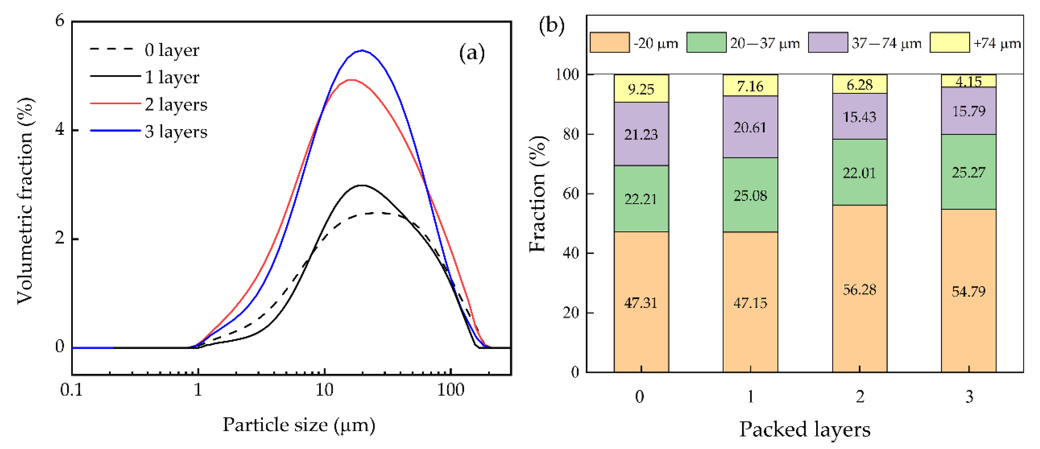
3.1. Flotation Performance

Column flotation tests were performed on the bauxite ore to evaluate the impact of the packing medium on flotation performance. As shown in Table 3, without packing, 50.57% of Al2O3 was recovered and Al/Si ratio of the concentrate was 5.16. When a single-layer of the medium was packed in the column, Al2O3 recovery and Al/Si ratio were increased to 53.19% and 6.17, respectively. Moreover, the ratio remained increasing as the number of packing layer increased. When three layers of the medium were packed in the column, an Al/Si ratio of 9.72 was obtained for the concentrate, indicating a higher flotation selectivity. By comparing the results shown in Table 3, it can be concluded that flotation performance of the bauxite ore was improved by increasing the number of packing layers. The optimal flotation performance was obtained when three layers of the medium were packed in the column. Using three-layer packing, Al2O3 content in the concentrate reached 58.40% at a recovery of 52.68% and Al/Si ratio of the concentrate reached as high as 9.72.
Figure 5 shows the particle-size distribution of the concentrates obtained with different number of packing layers. It could be seen from the curves that as the number of packing layer increases, the particle size of the concentrates tends to be finer. This change was more obvious when two layers of the medium were packed. When the column was not packed, the volumetric fraction of −20 µm particles was 47.31%. With increases in the number of packing layers, volumetric fraction of the −20 µm particles increased, and three-layer packing resulted in a concentrate comprising 54.79% of −20 µm particles. For particles of 20–37 μm size range, the volumetric fraction was increased by 3.06% by packing three layers of the medium. Totally, the volumetric fraction of −37 μm particles in the concentrates was increased by 2.71%, 8.77% and 10.54%, respectively, through single-layer, two-layer and three-layer packings. These increases indicate that the bauxite concentrates obtained by the medium-packed flotation column had finer particle sizes. The flotation experimental results show that Al/Si ratio of the concentrates was largely increased by the packing medium (see Table 3). Given these findings, it can be concluded that the increased volumetric fraction of finer mineral particles in the flotation concentrates was attributable to the preferential recovery of Al2O3 enriched particles. The installation of the packing medium inside the flotation column led to improvements in fine-grained bauxite recovery.

3.2. Turbulence Kinetic Energy Characteristics

A previous study [20] has shown that the installation of packing medium in a flotation column will change the structural parameters of the column, thus changing the turbulent environment inside the column during flotation process. According to the results of the flotation experiments (Table 3), flotation performance of the bauxite ore was improved with an increase in the number of packing layers. CFD was capable of simulating flows and predicting flotation process by providing visualized data [21,22,23]. Therefore, CFD technology was deployed to numerically analyze the collection zone of the flotation column with an air-water two-phase system. Impact of the packing medium on the turbulent environment in the collection zone was first studied. Changes in the flow field inside the flotation column as a function of the number of packing layers were then analyzed. Figure 6 shows the distribution characteristics of turbulence kinetic energy (TKE) in the collection zone as a function of the number of packing layers.
It can be seen from figure that in the absence of packing medium, areas with higher TKE were concentrated near the central axis, and TKE decreased along the axial direction. After the flotation column being packed with the medium, TKE values of the entire collection zone were significantly reduced. The maximum value of TKE in selected areas reduced from more than 1.0 × 10⁻² m2/s2 to 0.5 × 10⁻² m2/s2. Therefore, the packing medium could effectively reduce the turbulence kinetic energy of the collection zone. Larger TKE values normally represent higher pulsation velocity of turbulent vortex. Overall, a milder turbulent environmental in the collection zone was provided by the packing medium.
For medium-packed columns, larger TKE values in the collection zone were concentrated in areas immediately underneath the medium and were distributed in a dovetail shape between the packing layers. In the cased of less than four layers of packing, a stepwise decrease of TKE occurred along the axis. Therefore, the multilayer packing method could optimize the TKE distribution and form turbulent vortexes with different pulsation velocities. As the number of packing layer increased, TKE in the flotation column gradually decreased. With single or two layers of packing, TKE distributions in two adjacent areas separated by the packing medium in the collection zone were completely different, however the contrasts decreased when three packing layers were employed. The stepwise decreasing distribution of TKE in the axial direction gradually disappeared, and the fluid in the collection zone was transformed into a uniform flow.

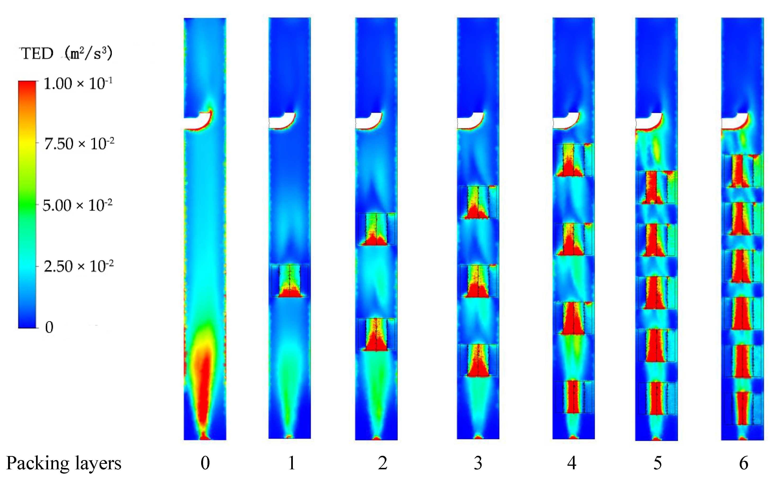
3.3. Turbulence Eddy Dissipation Characteristics

Turbulence eddy dissipation (TED) represents the turbulence kinetic energy loss of a unit mass of fluid in a unit time. It is normally utilized to characterize the rate at which a large vortex splits into small ones. A higher TED means that turbulent flow energy and the turbulent vortex scale change more rapidly. Figure 7 shows the influence of the number of packing layer on TED in the column. It can be seen from figure that in the absence of packing medium, larger TED occurred at the bottom and gradually decreased along the central axis. After installing the medium in the column, TED in the entire collection zone was significantly reduced. In the simulation model, slip velocity on the surface of the column and medium walls was assumed to be null. Therefore, the cloud diagram showed a relatively high turbulent dissipation rate. As the number of packing medium increased, TED in the collection zone gradually decreased. When the column was packed with four layers of the medium, TED in the collection zone gradually changed from cascade distribution to axial uniform distribution. This feature was consistent with the distribution of TKE.

3.4. Relationship Model between Turbulence and Multilayer Packing

A volumetric average value of TKE was used to evaluate turbulent characteristics of the collection zone under different packing conditions. As shown in Figure 8, in the absence of the packing medium, the average TKE of the flow field in the collection zone was 1.08 × 10⁻² m2/s2. When a single layer of the medium was packed, the average TKE decreased to 5.44 × 10⁻³ m2/s2 and further decreases occurred with increased in the number of packing layers. TED in the flow field showed a similar pattern as TKE, gradually decreasing from 3.71 × 10⁻² m2/s3 to around 1.00 × 10⁻² m2/s3. Therefore, packing of the medium greatly reduced TKE and TED in the flotation column, which means that turbulent pulsation velocity in the collection zone decreased. The decreases contributed to the formation of a relatively low energy turbulent environment. Additionally, when the number of packing layers reached three, the declining rate of TKE and TED tended to be minimal, which indicates that adding more layers of the medium had negligible impact on turbulent intensities in the flotation column.
From the quantified data, it can be seen that TKE and TED share a similar trend as the number of packing layer increased. Using the curve-fitting on these results, it was found that changes in the TKE and TED values as a function of the number of packing layers can be presented by the equations below:
k = 0.0021 + 0.0086 exp ( 0.95 n )
ε = 0.0098 + 0.027 exp ( 2.2 n )
where n is the number of medium packed in column.
The equations could be used to estimate the relationship between turbulent characteristics and the number of packing layer in a flotation column. According to the equations, the average TKE under the extreme packing condition was 2.1 × 10⁻³ m2/s2 and the average TED was 9.8 × 10⁻³ m2/s3.

3.5. Fluid Velocity Characteristics

A comparison of fluid velocity distribution in axial between unpacked and packed collection zone was conducted and the results are shown in Figure 9. For the collection zone without packing, there was a region where fluid velocity changes rapidly near the air inlet at the bottom of the column. The fluid velocity near the air inlet was much higher than other areas. The rapid rise of the air phase led to an upward movement of the nearby liquid along the central axis. After that, the flow regime gradually changed to a downward flow under the driving force of gravity. The multilayer packing weakens and disperses the area of liquid phase having high flowrates. In the absence of the packing medium, the axial velocity distribution in the flotation column was exceedingly uneven. The maximum velocity at Z = 0.10 m from the bottom reached 0.43 m/s, while at other heights, maximum velocity of the fluid was only around 0.2 m/s. After packing with medium, the characteristics of the axial flow were significantly changed and a stepwise decrease in fluid velocity occurred in the axial direction. Therefore, it can be concluded that the packing medium optimizes the characteristics of the velocity field of fluid inside the flotation column and affects the flotation hydrodynamic environment.

4. Discussion

The hydrodynamic environment of slurry has direct impacts on the movement and interaction of particles and bubbles [19,24]. In this research, multilayers of a medium were packed evenly in the collection zone of a self-designed flotation column. As a result, the original intensively turbulent environment was weakened and dispersed into several units with different turbulent intensities in axial (as presented in Figure 6 and Figure 7). Figure 10 shows a schematic of the impact of multilayer packing on the hydrodynamic conditions inside a flotation column. The multiple units serve as fluid screens in axial. When slurry enters the flotation column, particles that are easy to float are collected in the upper low turbulence unit, while particles that are difficult to float can be collected in the high turbulence unit at the bottom. In this way, flotation recovery is enhanced. Mineral particles with different properties are screened stage-by-stage, resulting in a higher separation efficiency. Based on the bauxite flotation tests performed in this study, silicon content of the concentrate decreased from 10.95% to 6.01%, corresponding to improvements in Al/Si ratio from 5.16 to 9.72.

5. Conclusions

In this study, a novel medium was designed and packed in the collection zone of a flotation column. Combining findings from the flotation experiments and CFD simulations, the impact of multilayer medium packing on the flotation performance of a bauxite ore was evaluated and the underlying mechanisms were revealed. The conclusions are as follows:
  • The packing medium significantly reduced the turbulence intensity in the collection area of the flotation column and changed the distribution characteristics of turbulence in the collection zone;
  • Multilayer packing resulted in several units with different turbulent intensities in the collection zone. These units are connected in series along the axial direction, leading to the formation of multi-stage environments with varying turbulent intensities, which are suitable for flotation separation;
  • Packing the medium in the collection zone of a column can improve bauxite flotation performance and enhance the separation of aluminum minerals from silicon minerals. With three-layers of packing, the recovery of Al2O3 increased by 2.11% and the aluminum-silicon content ratio improved from 5.16 to 9.72.

Supplementary Materials

The following are available online at https://www.mdpi.com/2075-163X/10/7/594/s1, Part A: Particle size analysis of the feed slurry, Part B: Mesh independence verification, Part C: Additional boundary conditions; Figure S1: Particle-size distribution of the slurry fed to the flotation column, Figure S2: Schematic of the media packed in the flotation column, Figure S3: Simulation results obtained using different mesh numbers.

Author Contributions

Conceptualization, methodology and formal analysis, P.Z.; investigation, Y.Z. and Z.Z.; writing—original draft preparation, P.Z.; formal analysis and writing—review and editing, W.Z.; supervision and project administration, L.O. All authors have read and agreed to the published version of the manuscript.

Funding

This work was financially supported by the National Natural Science Foundation of China (No. 51674291) and the Fundamental Research Funds for the Central Universities of Central South University (No. 2017zzts009). Key Laboratory of Hunan Province for Clean and Efficient Utilization of Strategic Calcium-containing Mineral Resources (No. 2018TP1002).

Acknowledgments

We acknowledge Beijing Lanwei Technology Co., Ltd. for providing simulation platform.

Conflicts of Interest

The authors declare no conflicts of interest.

References

  1. Wang, G.; Ge, L.; Mitra, S.; Evans, G.M.; Joshi, J.B.; Chen, S. A review of CFD modelling studies on the flotation process. Miner. Eng. 2018, 127, 153–177. [Google Scholar] [CrossRef]
  2. Yianatos, J.B. Fluid flow and kinetic modelling in flotation related processes: Columns and mechanically agitated cells—A review. Chem. Eng. Res. Des. 2007, 85, 1591–1603. [Google Scholar] [CrossRef]
  3. Kursun, H.; Ulusoy, U. Zinc recovery from lead-zinc-copper complex ores by using column flotation. Miner. Process. Extr. Metall. Rev. 2012, 33, 327–338. [Google Scholar] [CrossRef]
  4. Pyecha, J.; Lacouture, B.; Sims, S.; Hope, G.; Stradling, A. Evaluation of a MicrocelTM sparger in the Red Dog column flotation cells. Miner. Eng. 2006, 19, 748–757. [Google Scholar] [CrossRef]
  5. Oliveira, M.S.N.; Ni, X.W. Effect of hydrodynamics on mass transfer in a gas-liquid oscillatory baffled column. Chem. Eng. J. 2004, 99, 59–68. [Google Scholar] [CrossRef]
  6. Cheng, G.; Cao, Y.; Zhang, C.; Jiang, Z.; Yu, Y.; Mohanty, M.K. Application of novel flotation systems to fine coal cleaning. Int. J. Coal Prep. Util. 2020, 40, 24–36. [Google Scholar] [CrossRef]
  7. Harbort, G.; Clarke, D. Fluctuations in the popularity and usage of flotation columns—An overview. Miner. Eng. 2017, 100, 17–30. [Google Scholar] [CrossRef]
  8. Anderson, C.J.; Harris, M.C.; Deglon, D.A. Flotation in a novel oscillatory baffled column. Miner. Eng. 2009, 22, 1079–1087. [Google Scholar] [CrossRef] [Green Version]
  9. Moys, M.H.; Engelbrecht, J.A. Simulation of the behaviour of flexible baffles in flotation columns. Chem. Eng. J. Biochem. Eng. J. 1995, 59, 33–38. [Google Scholar] [CrossRef]
  10. Huang, G. Fundamental Theory Research and Application of Horizontal Baffled Flotation Column. Ph.D. Thesis, Central South University, Changsha, China, 2009. (In Chinese). [Google Scholar]
  11. Çilek, E.C.; Yilmazer, B.Z. Effects of hydrodynamic parameters on entrainment and flotation performance. Miner. Eng. 2003, 16, 745–756. [Google Scholar] [CrossRef]
  12. Yan, X.; Chen, Z.; Wang, L. Computational fluid dynamics (CFD) numerical simulation and particle image velocimetry (PIV) measurement of a packed flotation column. Physicochem. Probl. Miner. Process. 2017, 100, 155–165. [Google Scholar] [CrossRef]
  13. Li, Q.; Li, L.; Zhang, M.; Lei, Z. Modeling flow-guided sieve tray hydraulics using computational fluid dynamics. Ind. Eng. Chem. Res. 2014, 53, 4480–4488. [Google Scholar] [CrossRef]
  14. Ding, Y.; Wu, Y.; Li, D.; Zheng, J. Technical note a study on the mixing characteristics of a packed flotation column. Miner. Eng. 2001, 14, 1101–1105. [Google Scholar] [CrossRef]
  15. Xia, Y.K.; Peng, F.F.; Wolfe, E. CFD simulation of alleviation of fluid back mixing by baffles in bubble column. Miner. Eng. 2006, 19, 925–937. [Google Scholar] [CrossRef]
  16. Farzanegan, A.; Khorasanizadeh, N.; Sheikhzadeh, G.A.; Khorasanizadeh, H. Laboratory and CFD investigations of the two-phase flow behavior in flotation columns equipped with vertical baffle. Int. J. Miner. Process. 2017, 166, 79–88. [Google Scholar] [CrossRef]
  17. Zhang, M.; Li, T.; Wang, G. A CFD study of the flow characteristics in a packed flotation column: Implications for flotation recovery improvement. Int. J. Miner. Process. 2017, 159, 60–68. [Google Scholar] [CrossRef]
  18. Zhang, M.; Li, T.; Ma, S.; Wang, G. An experimental study of copper sulfide flotation in a packed cyclonic–static microbubble flotation column. Sep. Sci. Technol. 2018, 53, 2238–2248. [Google Scholar] [CrossRef]
  19. Nguyen, A.V.; An-Vo, D.A.; Tran-Cong, T.; Evans, G.M. A review of stochastic description of the turbulence effect on bubble-particle interactions in flotation. Int. J. Miner. Process. 2016, 156, 75–86. [Google Scholar] [CrossRef]
  20. Finch, J.A. Column flotation: A selected review—Part IV: Novel flotation devices. Miner. Eng. 1995, 8, 587–602. [Google Scholar] [CrossRef]
  21. Sarhan, A.R.; Naser, J.; Brooks, G. Bubbly flow with particle attachment and detachment—A multi-phase CFD study. Sep. Sci. Technol. 2018, 53, 181–197. [Google Scholar] [CrossRef]
  22. Karimi, M.; Akdogan, G.; Bradshaw, S.M. A CFD-kinetic model for the flotation rate constant, Part II: Model validation. Miner. Eng. 2014, 69, 205–213. [Google Scholar] [CrossRef]
  23. Xu, G.; Luxbacher, K.D.; Ragab, S.; Xu, J.; Ding, X. Computational fluid dynamics applied to mining engineering: A review. Int. J. Min. Reclam. Environ. 2017, 31, 251–275. [Google Scholar] [CrossRef]
  24. Li, S.; Schwarz, M.P.; Feng, Y.; Witt, P.; Sun, C. A CFD study of particle-bubble collision efficiency in froth flotation. Miner. Eng. 2019, 141, 105855. [Google Scholar] [CrossRef]
Figure 1. X-ray diffraction pattern of the bauxite ore.
Minerals 10 00594 g001
Figure 2. Experiment apparatus used for bauxite flotation: (a) flotation column system; (b) packing medium.
Minerals 10 00594 g002
Figure 3. Conditioning procedures used for the flotation tests.
Minerals 10 00594 g003
Figure 4. Simulation model and mesh of the flotation column: (a) Schematic diagram; (b) Geometry; (c) Mesh.
Minerals 10 00594 g004
Figure 5. Particle-size distribution of the flotation concentrates obtained with different packing layers: (a) Volumetric fraction; (b) Cumulative fraction at specific value.
Minerals 10 00594 g005
Figure 6. Influence of packing layers on turbulence kinetic energy characteristics in column.
Minerals 10 00594 g006
Figure 7. Influence of packing layers on turbulence eddy dissipation characteristics in column.
Minerals 10 00594 g007
Figure 8. Influence of packing layers on volumetric average of (a) turbulence kinetic energy (TKE) and (b) turbulence eddy dissipation (TED).
Minerals 10 00594 g008
Figure 9. Comparison of fluid velocity distribution in axial between unpacked and packed columns: (a) Contour of no packing; (b) Contour of packing three layers; (c) Line chart of no packing; (d) Line chart of packing three layers.
Minerals 10 00594 g009
Figure 10. Schematic of hydrodynamic conditions in the collection zone of a flotation column.
Minerals 10 00594 g010
Table 1. Chemical analysis of the bauxite ore.
ComponentFeSTiO2Na2OAl2O3SiO2P2O5MgOK2O
Content (%)5.190.973.760.2544.6720.680.230.502.76
ComponentCaOClCuCeSrZrCrOther
Content (%)2.770.0350.0260.0820.0530.0530.03018.03
Table 2. Boundary conditions of the simulation model.
BoundaryTypeParameter
Air InletVelocity inlet0.13 m/s
Air outletDegassing
Water InletVelocity inlet0.18 m/s
Water outletPressure outlet101.325 kPa
Wall OutsideWall
Water pipeWall
MediumWall
SymmetrySymmetry
Table 3. Boundary conditions of simulation model.
Packed LayersSampleContent of Al2O3 (%)Content of SiO2 (%)Al2O3/SiO2Recovery of Al2O3 (%)
No packingConcentrate56.5510.955.1650.57
Tailing40.0629.911.3449.43
Feed46.9921.942.14100.00
One layerConcentrate57.719.366.1753.19
Tailing37.5130.421.2346.81
Feed46.0921.472.15100.00
Two layersConcentrate55.288.256.7056.17
Tailing37.1432.611.1443.83
Feed45.5321.342.13100.00
Three layersConcentrate58.406.019.7252.68
Tailing37.0332.861.1347.32
Feed45.8821.752.11100.00

