1. Introduction
Magnetic reconnection in highly conductive plasmas is a fundamental physical process in which the energy of a magnetic field is efficiently converted into the energy of plasma and accelerated particles [
1,
2,
3,
4,
5,
6,
7]. Magnetic reconnection processes provide the basis for many flare-type phenomena that take place in space and laboratory plasmas [
8,
9,
10,
11,
12]. Such phenomena include flares on the Sun and stars, substorms in the magnetospheres of the Earth and other planets, and some processes in laboratory plasma, such as disruption instabilities in tokamak plasmas, non-stationary phenomena in theta pinches with a reverse field, plasma focus, etc.
Magnetic reconnection processes occur in spatial regions where magnetic field lines in opposite or different directions can closely approach each other. In such areas, a high-density electric current is concentrated, which usually takes the form of a current sheet and separates magnetic fields of various directions [
13,
14].
The magnetic reconnection phenomena are intimately associated with the dynamics of current sheets. These phenomena have been studied for many decades, on the basis of spacecraft observations, by methods of theoretical physics, analytically and numerically, as well as using dedicated laboratory experiments [
13,
15].
An outstanding contribution to the progress of the theory of current sheets was performed by S.I. Syrovatskii, who advanced the conception that flare-type phenomena evolve on the basis of the formation of current sheets and their subsequent disruption [
3,
4,
16,
17]. The relatively slow development of a current sheet in magnetized plasma gives rise to the gradual accumulation of magnetic energy and produces a pre-flare situation. The flare itself arises from the rapid disruption of the current sheet followed by the transformation of excessive magnetic energy into the energy of plasma and accelerated particles. In this case, the characteristic transverse dimensions of the sheet (in a plane perpendicular to the direction of the current), which may differ significantly, take on great significance.
Indeed, the reservoir of magnetic energy concentrated in the vicinity of the sheet is determined by its larger transverse size or sheet width. At the same time, a relatively short time of sheet disruption and magnetic energy transformation into the energy of plasma and accelerated particles is controlled by the smaller transverse size of the sheet or its thickness.
Investigations of current sheets on the basis of special laboratory experiments make it possible to come closer to understanding the nature of phenomena occurring in space, as well as to reproduce certain of these phenomena within the frames of “limited modeling” [
18,
19,
20,
21]. This means that if the characteristic dimensionless parameters were much greater (less) than unity in space, then they should also be, accordingly, greater (less) than unity in laboratory conditions.
Unlike current sheets, which arise spontaneously in outer space, the current sheets produced in laboratory experiments have, as a rule, a certain type of symmetry. The most popular are current sheets with either toroidal [
22,
23,
24,
25,
26] or translational symmetry [
27,
28,
29,
30,
31].
In this paper, we consider the formation and evolution of straight current sheets with translational symmetry, which are produced in two-dimensional (2D) magnetic configurations with an X-type null line [
29,
32,
33,
34]. This approach makes it possible to effectively compare experimental data with the results of theoretical analysis. At the same time, the translational symmetry of current sheets allows us to apply methods of plasma diagnostic, such as holographic interferometry [
35], as well as work out proposals for employment dynamic processes in current sheets for technological purposes.
The structure of the paper is as follows. In
Section 2, we display the non-uniform 2D magnetic field with the first-order X-type null line. Here, we describe the experimental CS-3D device, including the systems for the formation of magnetic configurations with the
X-line, the preparation of the initial plasma, and the excitation of the electric current in the plasma. The scheme of magnetic measurements is also presented in
Section 2.
In
Section 3, we first consider theoretical views related to the peculiarities of a magneto-sonic wave that precede the formation of a current sheet and the experimental results on the wave propagation from the plasma outer boundaries toward the
X-line. Small initial perturbations of the magnetic field increased sharply near the
X-line and resulted in the current sheet formation.
Section 4 is concentrated on the structure of magnetic fields and plasma currents in the vicinity of a current sheet formed in a magnetic configuration with an X-type null line. Both the electric current and plasma are compressed into a planar 2D sheet, which accumulates an excess of magnetic energy, and the current sheet is symmetric about two mutually perpendicular planes.
In
Section 5, we show the impact of Hall currents on the structure of the current sheets. Both the electric currents and magnetic fields become 3D as a result of an out-of-plane magnetic field component caused by Hall currents.
In
Section 6, we consider the processes of plasma acceleration from the central region of the current sheet to both side edges, which bring about the generation of inverse currents at the side edges of the sheet.
Section 7 demonstrates that in regions with inverse currents, the out-of-plane magnetic field became directed opposite to the earlier time moments. This means that the Hall currents are directed outward at the side edges of the sheet.
Section 8 is concentrated on the connection between the Ampère’s forces that appear at the edges of the current sheet and the relatively short duration of high-speed plasma flows. The forces at the sheet edges are comparable to the forces in the central region and should effectively terminate plasma flows.
2. Magnetic Field with the X-Line and Experimental CS-3D Device
The basic component of the experimental CS-3D device [
36] is a magnetic configuration containing a singular X-type line. The 3D magnetic field in the vicinity of the first-order
X-line may be presented as follows:
Here, the singular line coincides with the
z-axis.
h is the gradient of the transverse magnetic field with the magnetic field lines arranged in the (
x,
y) plane and
is the longitudinal magnetic field component. When
= 0, the 3D magnetic configuration is turned to a 2D configuration, and the singular line becomes the null line. The structure of the 2D magnetic configuration with the X-type null line is shown in
Figure 1. One can see that along with the translational symmetry in the z-direction, the magnetic field is also symmetric about the planes:
x = 0;
y = 0;
x =
y; and
x = −
y.
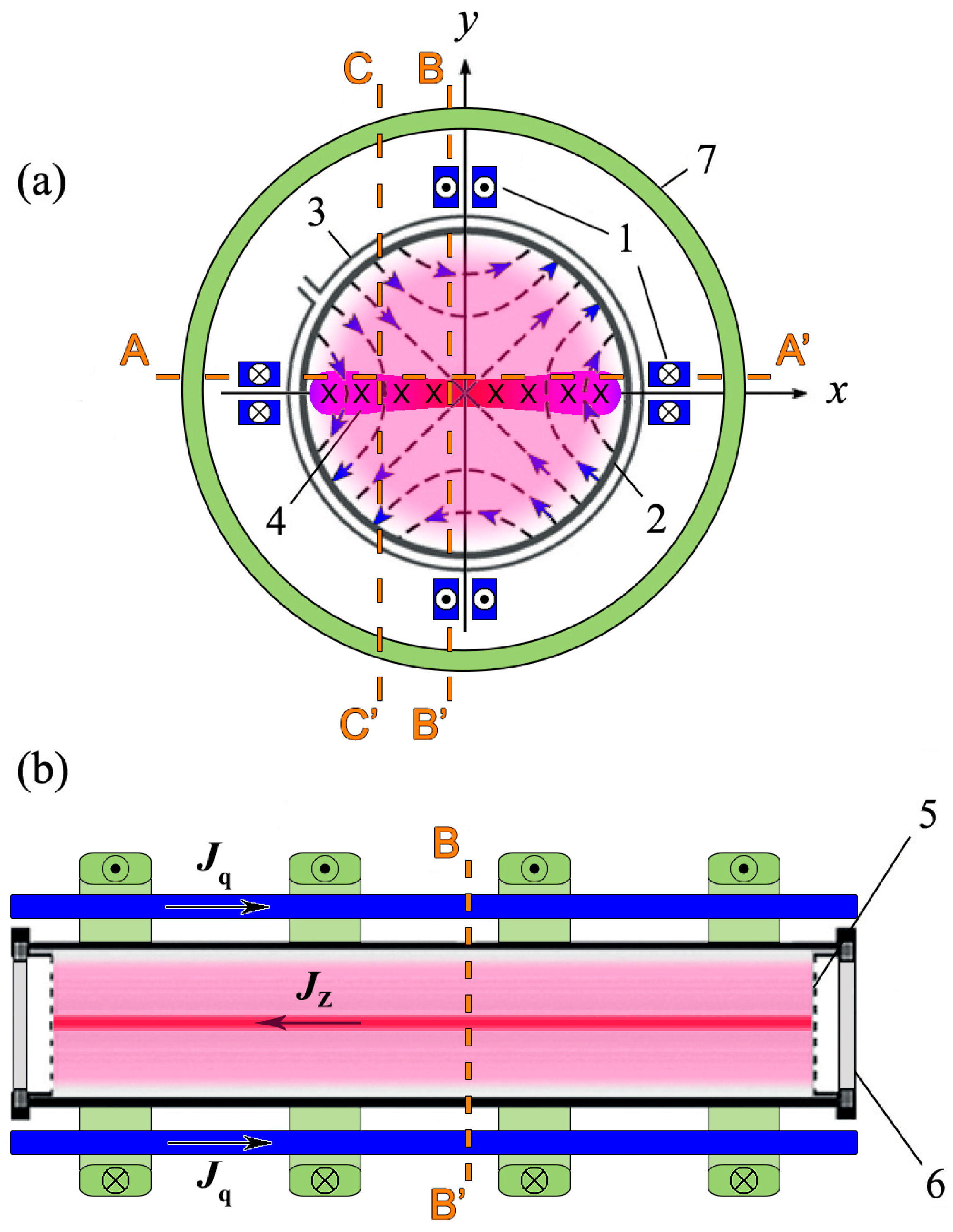
Magnetic configurations (1) are formed in the experimental CS-3D device (
Figure 2) by the superposition of two magnetic fields: a 2D magnetic field with a null line at the
z-axis and a uniform longitudinal magnetic field,
. The 2D magnetic field is produced by currents in a system of eight straight conductors, which are located parallel to the axis of a cylindrical vacuum chamber. All conductors are connected in series, the current in the system varies between 40 kA and 70 kA, the half-period of the current is 400 µs, and the gradient
h of the 2D magnetic field may be varied in the range
h = 0.4 ÷ 0.7 kg/cm. This magnetic field and the longitudinal magnetic field
are quasi-stationary relative to the plasma processes. The longitudinal magnetic field
is produced by currents in a system of identical cylindrical coils; the strength of the
field may vary between 0 and 6 kg.
The quartz vacuum chamber, 18 cm in diameter and 100 cm in length, is preliminary filled with one of the noble gases: He, Ar, Kr, or Xe. The initial plasma with a density of
≈
÷
is produced in the magnetic field (1) by the theta-discharge (
≈ 40 kV, T/2 ≈ 4 µs) with strong pre-ionization. Then, a pulsed voltage
≈ 5 ÷ 10 kV is applied between two grid electrodes inserted into the vacuum chamber from both edges and separated at a distance Δ
z = 60 cm. The voltage
brings about the onset of the electric current
with sinusoidal time dependence (half-period ≈ 6 μs, amplitude ≈ 50 kA). After a short time interval, the formation of a current sheet takes place, which is also shown in
Figure 2.
A distinctive property of the device is the uniformity in the
z-direction of both the magnetic field (1) and the initial plasma in the space between two electrodes. This property has an essential advantage for the application of some methods of plasma diagnostics, like holographic interferometry, and especially the illustrative presentation of experimental results [
35,
37].
The magnetic fields produced by plasma currents were measured by three-component magnetic probes, which were moved either along the surface of the sheet (line AA’,
y = 0.8 cm) or across the sheet at two distances from the
X-line: BB’,
x = −0.8 cm, and CC’,
x = −5.5 cm;
Figure 2. Time dependences of three mutually perpendicular components of the magnetic field were recorded, and then data processing was carried out to obtain the structures of the magnetic fields, plasma currents, and Ampère’s forces, as well as their evolution in time [
38,
39].
It is important to point out that current sheets produced in the CS-3D device have the advantage of a fixed position in the (x,y) plane, which is dictated in turn by the position of the X-line in the magnetic field (1).
The 2D distributions of electron concentration
in the (
x,
y) plane were recorded by the methods of holographic interferometry or cine-holography [
37,
40].
In this paper, our consideration is restricted by the structure, symmetry, and dynamics of current sheets formed in 2D magnetic fields with the null line without the field.
3. Formation of a Current Sheet
The initial stage of the current sheet formation in a magnetic field with a singular line X-type line was considered theoretically in the approximation of cold plasma when magnetic forces dominated and the plasma pressure was negligible [
3,
4,
16,
41,
42]. It was found that any small local perturbation of the initial state results in the excitation of magneto-sound and Alfven waves, which propagate in magnetized plasma at the Alfven speed:
Here, is the ion density, and is the ion mass.
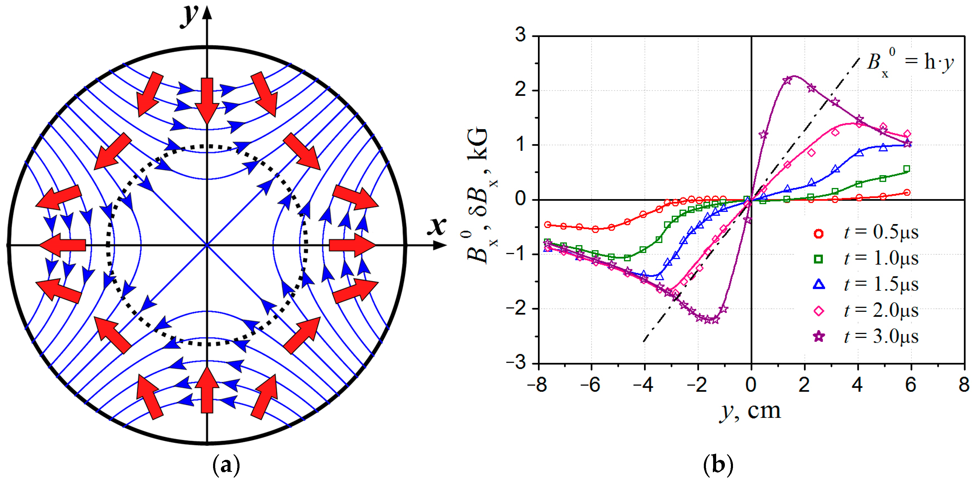
In a non-uniform magnetic field (1), the local speed
of the magneto-sound wave is also non-uniform, and the wave should be slowed down by approaching the
X-line. As a result, any small perturbation that appeared somewhere away from the
X-line has to be transformed into a cylindrical magneto-sound wave converging toward the
X-line;
Figure 3a. In the course of radial conversion, the speed of the wave decreases, while the amplitudes of all perturbations (magnetic fields, plasma densities, velocities, and currents) should grow, and the linear wave may evolve into a non-linear one.
Behind the front of the magneto-sound wave, the velocities of plasma flows display the 2D properties. The velocity components
are directed toward the
X-line, whereas the
components are directed outward, as shown schematically in
Figure 3a. Peculiarities of the plasma flow velocities manifest a tendency for the formation of a 2D current sheet and plasma compression into the sheet.
The principal features of the magneto-sound wave that propagates in a magnetic field with an
X-line can be followed by experimental results obtained with the CS-3D device. The application of a pulsed voltage between the electrodes and the excitation of the electric field
produce small perturbations
at the plasma outer boundaries (
Figure 3b,
t = 0.5 μs). Afterward, the perturbations propagate from both sides to the inner plasma regions in the direction of the
X-line located at
y = 0; the speed of the wave motion decreases, and the magnitudes of
grow (
Figure 3b,
t = 1.0–1.5 μs). Until the wave arrived close enough to the
X-line, the perturbations
remain relatively small compared to the component
of the initial magnetic field (1). The density of the electric current at the front of the wave and changes in plasma density are also quite small [
35,
40], so in real plasma, the magneto-sound wave remains a wave of small amplitude.
Figure 3b provide evidence that the perturbations
are nearly symmetric about the plane
y = 0.
As the wavefront approaches the
X-line, the formation of a current sheet takes place. This process manifests itself in a considerable increase in perturbations
and their gradients, which are proportional to the plasma current density
. Another distinctive property is a noticeable decrease in the size
δy of the region where the plasma current is localized;
Figure 3b,
t = 2.0–3.0 μs. It follows that the plasma current
is effectively compressed in the
y-direction, giving rise to the current sheet.
4. Characteristics of 2D Current Sheets Formed in a Magnetic Field with an X-Line
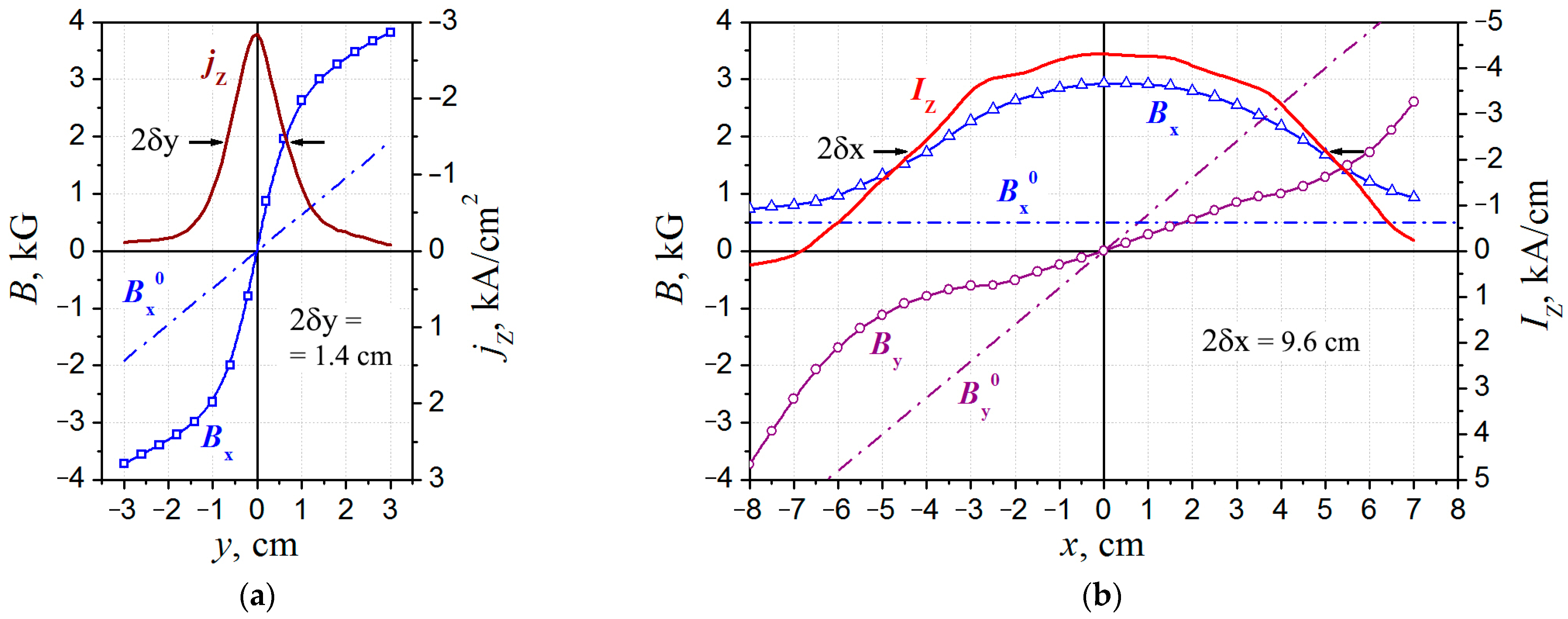
The structure of currents and magnetic fields in the vicinity of the current sheet was determined from magnetic measurements carried out across the sheet (in the
y-direction;
Figure 4a) and parallel to its surface (in the
x-direction;
Figure 4b) [
38,
43]. Notice that the magnetic fields presented in
Figure 4a,b are the actual magnetic fields, which include the fields produced by plasma currents and the initial field (1).
Figure 4a demonstrates a significant increase in the tangential magnetic field component
compared to
in the vicinity of the sheet mid-plane, where
attained values of ≈3 ÷ 4 kG. The maximum of the current density,
≈
, was located at the sheet mid-plane, and the sheet thickness, i.e., the size of the current region along the
y-axis, was 2
≈ 1.4 cm at a half-maximum level of the current density. It is evident in
Figure 4a that the distributions of currents and magnetic fields are symmetric about the plane
y = 0.
The distributions of the magnetic field components,
and
, along the line
y = Δ
y = 0.8 cm are presented in
Figure 4b together with the current
, which was determined as the integral of
over the region │
y│≤ Δ
y. Calculations of
were carried out by taking into account the symmetry of the current sheet about the plane
y = 0.
It can be seen in
Figure 4b that the current region was extended in the
x-direction, and the size of this region was 2
≈ 9.6 cm at the half-maximum level of the current
. The magnetic field component
tangential to the surface of the sheet exceeded its initial value,
several times, so that
>>
. By contrast, the normal component
became lower compared to the normal component
in the initial magnetic field (1). Notice that the distributions of currents and magnetic fields are symmetric about the plane
x = 0;
Figure 4b.
The results presented in
Figure 4a,b demonstrate the formation of a flat 2D current sheet compressed in the
y-direction that extended along the
x-direction, with a significant increase in the magnetic field near the surface of the sheet. It follows that an accumulation of excessive magnetic energy occurs in the vicinity of the current sheet. Under special conditions, this energy can be converted into thermal and kinetic plasma energy and fluxes of accelerated particles.
In parallel with the electric current contraction and formation of the current sheet, the plasma was also effectively compressed into a flat plasma sheet. The process may be followed in
Figure 5, which demonstrates 2D distributions of electron density
at successive instants of time during sheet formation. It can be seen that a rapid increase in plasma density had come about in a short time interval. Note that the plasma sheet is also relatively symmetric about both planes:
y = 0 and
x = 0.
The 2D plasma distributions shown in
Figure 5 were registered in a single pulse of the CS-3D device by employing a specially designed cine-holographic setup [
40]. The application of the interference holographic methods made it possible to obtain apparent information about the plasma structure due to the uniform character of magnetic fields and plasma in the
z-direction that presents a distinctive feature of the CS-3D device.
The experimental results reported above made us conclude that the basic characteristics of the current sheets are in good agreement with theoretical concepts. Actually, both the electric current and plasma are compressed into a flat 2D sheet, the enhanced magnetic fields are symmetrical about two mutually perpendicular planes, and the currents in the sheet flow parallel to the X-line.
At the same time, real current sheets are dynamic objects with intense plasma flows and rapid changes in the magnetic fields. As a consequence, it is possible the appearance of electric fields and currents differ in direction from the main current in the sheet. Such effects should lead to a significant complication of the structure of magnetic fields and currents and the modification of plasma dynamics in the current sheets.
5. Hall Currents and Out-of-Plane Magnetic Fields in the Current Sheet
It would appear reasonable that when a current sheet was formed in a 2D magnetic field with a null line, and the current
was aligned with the null line, the magnetic field should include only two components,
and
, and the magnetic field lines should lie in the (
x,
y) plane. At the same time, it has been revealed that the out-of-plane magnetic field component,
could appear in such current sheets [
39]. Space-temporal characteristics of the
component indicated that it resulted from the generation of Hall currents produced by the motion of electrons relative to low-mobility ions.
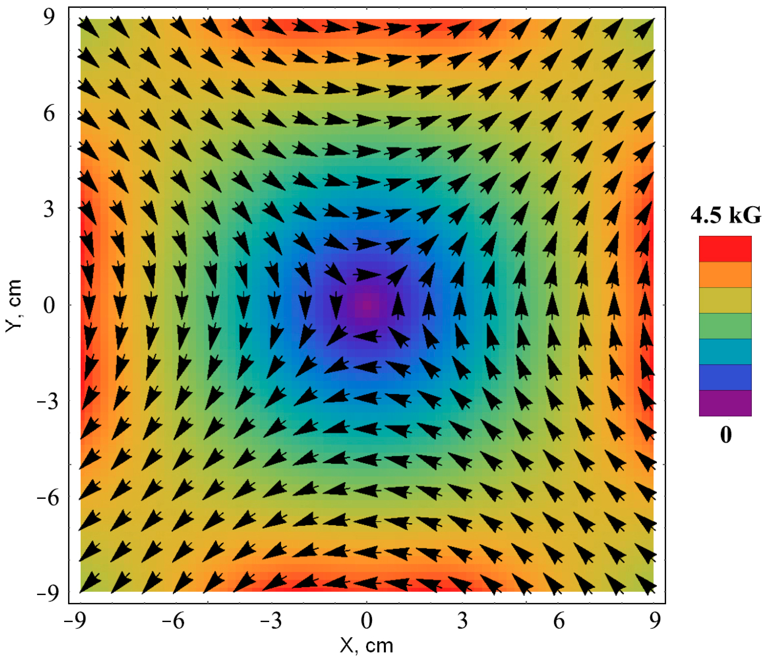
Some typical features of the out-of-plane magnetic field component and the Hall currents may be seen in
Figure 6. The distribution of
at a distance
x = −5.5 cm from the
X-line shows that the
component was in the opposite direction on both sides from the sheet mid-plane (
y = 0), where the current density
≈
reaches its maximum value;
Figure 6a. (Here, it was taken into account that ∂/∂
z ≈ 0.) In the vicinity of the mid-plane, the current
(
y ≈ 0) was directed from the sheet periphery toward the central region (
x ≈ 0), whereas at some distances from the mid-plane, the currents
were directed oppositely. It was established that currents
in both directions integrated over the y-coordinate completely compensate each other [
39].
The distribution of
along the current sheet mid-plane, at a distance of
y = −0.8 cm from this plane, is shown in
Figure 6b with the current density,
≈
. It can be seen that the
component was in the opposite direction at both sides from the plane (
x = 0).
Consequently, the direction of the out-of-plane magnetic field was reversed under crossing both symmetry planes (
x = 0) and (
y = 0) so that the
component formed an additional magnetic structure with quadrupole symmetry in the planar current sheet. This magnetic configuration was produced by the Hall currents, which were flowing in four closed-current circuits in the (
x,
y) plane, localized within the thickness of the current sheet, as is shown schematically in
Figure 6c.
The out-of-plane magnetic fields existed during a limited time interval at the initial stage of the current sheet evolution, and the heavier the plasma ions were, the longer the time interval was [
43]. Among other factors, this property confirms that the excitation of Hall currents was responsible for the appearance of out-of-plane magnetic fields in current sheets formed in 2D magnetic fields with a null line.
As a consequence, the structure of the current sheet became more complicated in the presence of Hall currents. The electric current and magnetic field included all three components, and the sheet symmetry changed significantly [
44].
6. Plasma Acceleration in Current Sheets and the Generation of Inverse Currents
The decay of the Hall currents (and their markers—the out-of-plane
components) is caused by the progressive motion of plasma ions in the wake of the electrons, which are traveling in the
x-direction. The acceleration of plasma ions occurs under the action of both the pressure gradient and Ampère’s forces:
Here,
,
, and
are the mass, concentration, and velocity of plasma ions,
p is the plasma pressure, and
is the density of Ampère’s forces. In most cases, the gradient
in the
x-direction is negligibly small in the current sheets [
45], so Ampère’s forces are crucial for accelerating the ions.
When a current sheet is formed in a 2D magnetic field, Ampère’s forces acting in the
x-direction are governed by the magnitudes and directions of both the current density
and the magnetic field component
:
Notice that the
component, which is normal to the mid-plane of the current sheet, plays a significant role in plasma acceleration. The distributions of
and
shown in
Figure 4b suggest that Ampère’s forces are oppositely directed at
x ≥ 0 and
x ≤ 0. It follows that plasma motion along the sheet surface should involve two jets directed oppositely, from the central region of the sheet to both side edges and symmetric about the plane (
x = 0).
Acceleration in the
x-direction resulted in increasing the ions’ kinetic energy, which could exceed several times the thermal energy of the ions [
46,
47,
48,
49]. We emphasize that plasma flows gain higher energy at the side edges of the sheet (at |
x| >> 0) and in the late stage of the current sheet evolution.
The inverse currents
come into play near the side edges of the sheet in the late stage of the sheet evolution [
38,
43]. The inverse currents of relatively small magnitudes are in the opposite direction relative to the basic current
in the main part of the sheet;
Figure 7,
t = 2.4; 4.5 μs.
There is a one-to-one correspondence between the excitation of inverse currents and the arrival of high-speed plasma flows to the sheet edges, where the
component attains the high magnitudes; see
Figure 4b. Actually, plasma motion in the transverse magnetic field results in the generation of an inductive electric field:
Of particular importance is that the direction of the field
should be opposite to the direction of the initial electric field that gave rise to the current sheet formation. As follows from Equation (5), inductive electric fields
should be non-uniform within the sheet width and increase sharply near the sheet edges where both plasma velocities │
│ and the │
│ component attain maximal magnitudes. In fact, the appearance of inverse currents was directly registered at the side edges of the current sheet;
Figure 7,
t = 2.4; 4.5 μs.
We emphasize that the inverse currents are caused by the excitation of inductive electric fields when high-speed plasma flows move across the strong transverse magnetic field. This effect is more pronounced near the side edges of the current sheet, and it is not associated with processes at the surface of the vacuum chamber. In addition, there is indirect evidence that the inverse currents come into play everywhere over the width of the current sheet, not only at the side edges. For more details, see [
43].
7. Appearance of the Out-of-Plane Magnetic Field in the Opposite Direction
According to the generalized Ohm’s law, the direction of the Hall current
in the current sheet is determined by the direction of the basic current
:
Consequently, it may be expected that in response to the excitation of the inverse current
, a Hall current
should appear opposite to its direction at the initial stage. The Hall currents are detected on the base of the registration of the out-of-plane magnetic field component
; see
Section 5.
Figure 8 demonstrates the distributions of the linear current
and the magnetic field
at two successive instants of time. It follows that there exists an adequate correlation between the directions of the basic current
and the Hall current [
43].
At the early time (
t = 1.5 μs,
Figure 8a), the linear currents
were in the same directions within the whole width of the current sheet. At this moment, the distribution
was similar to the distribution of the conventional quadrupole magnetic field produced by the Hall currents (see
Figure 6b). It follows that the electron’s motions, which produce the Hall currents, were directed from the central region of the sheet to both side edges.
However, the appearance of inverse currents
near the side edge of the sheet at
t = 2.4 μs was followed by changing the sign of the
component in this region;
Figure 8b. The change in the
sign indicates that at the edge of the sheet, the direction of the Hall currents became opposite compared to the earlier time moments. This means that electrons began to move from the side edges of the sheet toward its central region.
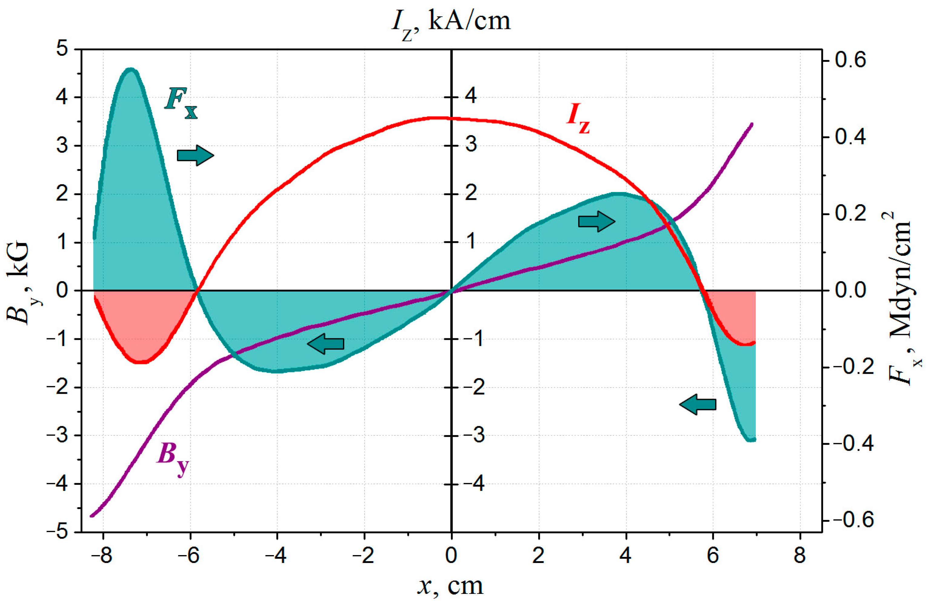
8. Braking Ampère’s Forces Responsible for Terminating High-Speed Plasma Flows
Another important phenomenon caused by the generation of inverse currents lies in the fact that the Ampère’s forces that appeared near the sheet edges were directed from the sheet periphery toward its center. Though the inverse currents were relatively small, the absolute magnitudes of the forces at the sheet edges were comparable to the forces in the central region of the sheet and might even exceed them; see
Figure 9 and [
50,
51]. As a consequence, the plasma dynamics became significantly modified since the forces at the edges of the sheet should slow down plasma flows, which were previously accelerated in the current sheet. The appearance of braking forces should prevent further plasma movement toward the sheet edges and could result in short durations of super-thermal plasma flows.
As was observed earlier, accelerated plasma flows are usually limited in time and length [
47,
48,
49]. At the same time, the energy of plasma flows depends on the work produced by Ampère’s forces in both directions. In particular, the work of braking forces should result in a significant decrease in the energy of plasma motion. A comparison of the work performed by Ampère’s forces in both directions, on the one hand, and changes in the energy of plasma flows, on the other hand, made it evident that the short durations of super-thermal plasma flows in the current sheet are caused by the work of braking forces at the regions with inverse currents [
50,
51].
We would like to recall that inverse currents are generated in the current sheets due to the motion of accelerated plasma flows. As a consequence, the forces that slowed down these flows or even stopped them appeared. In general cases, the effect of braking plasma flows caused by the generation of inverse currents should manifest itself when fast plasma flows enter into regions with strong transverse magnetic fields.
This effect may come into play when plasma jets accelerated at the distant region in the tail of the Earth’s magnetosphere move toward the Earth. By now, the inverse currents in the current sheet on the night side of the Earth’s magnetosphere were revealed at the fronts of plasma jets [
52,
53]. It was shown that there are common features in the processes, which occur in the Earth’s magnetosphere and laboratory experiments [
53].
9. Conclusions
In this short review, we present experimental results related to modifications of the current sheet’s structure, which occur due to processes of plasma dynamics. The straight current sheets are formed in two-dimensional (2D) magnetic configurations with an X-type null line on the base of the CS-3D setup. The symmetry properties are typical for both the magnetic configuration and the current sheets.
At the initial stage, which precedes the development of a current sheet, a magneto-sonic wave of cylindrical symmetry propagates from the outer plasma boundaries toward the null line of the magnetic field. The non-linear stage of wave motion gives rise to the formation of a 2D current sheet, which possesses two different dimensions in the plane perpendicular to the direction of the plasma current. In addition, the current sheet becomes symmetrical about two mutually perpendicular planes. The electric current and plasma are effectively compressed into the sheet, and the magnetic field increases significantly near the sheet’s surface. It follows that excessive magnetic energy is accumulated in the vicinity of the current sheet.
The excitation of Hall currents gives rise to out-of-plane magnetic fields of a quadrupole structure inside the current sheet, and in the mid-plane of the sheet, the Hall currents are directed inward. This phenomenon essentially changes the structure of the 2D planar current sheet; as a result, the magnetic fields and plasma currents become 3D.
We demonstrate that the real current sheet is a dynamic object with intensive plasma flows, which are accelerated by Ampère’s forces from the central region of the sheet toward both side edges. Eventually, the motion of super-thermal plasma flows gives rise to additional deformations of the current sheet.
When high-speed plasma flows come into the regions with strong magnetic fields, inductive electric fields and currents are generated inside the current sheet. It is important that these inductive currents are reversed compared to the basic current in the sheet. The inverse currents of the maximal amplitudes appear at the side edges of the sheet. Here, the out-of-plane magnetic fields also become reversed so that the Hall currents are directed outward in the sheet mid-plane (note that electrons are moving inward).
Another fundamental effect caused by inverse currents consists in the appearance of Ampère’s forces in opposite directions, which are comparable in amplitude to the forces in the central region. The braking forces at the side edges of the current sheet should effectively slow down plasma flows, which were accelerated previously. As a result, the high-speed plasma jets become confined both in time and space.
Hence, the simplest current sheets formed in a 2D magnetic field with a null line are exposed to dynamic processes in real plasma that result in complications of the sheet structure and the deterioration of its planar symmetry.


